DESIGN STANDARD DS 38-02 - Water Corporation · Design Standard No. DS 38-02 Flanged Connections...
52
Assets Delivery Group Engineering DESIGN STANDARD DS 38-02 Flanged Connections VERSION 1 REVISION 1 DECEMBER 2017
Transcript of DESIGN STANDARD DS 38-02 - Water Corporation · Design Standard No. DS 38-02 Flanged Connections...

Assets Delivery Group Engineering
DESIGN STANDARD DS 38-02
Flanged Connections
VERSION 1
REVISION 1
DECEMBER 2017

Design Standard No. DS 38-02
Flanged Connections
Uncontrolled if Printed Page 2 of 52
Ver 1Rev 1
© Copyright Water Corporation 2013- 2017
FOREWORD
The intent of Design Standards is to specify requirements that assure effective design and delivery of fit for purpose
Water Corporation infrastructure assets for best whole-of-life value with least risk to Corporation service standards
and safety. Design standards are also intended to promote uniformity of approach by asset designers, drafters and
constructors to the design, construction, commissioning and delivery of water infrastructure and to the
compatibility of new infrastructure with existing like infrastructure.
Design Standards draw on the asset design, management and field operational experience gained and documented
by the Corporation and by the water industry generally over time. They are intended for application by Corporation
staff, designers, constructors and land developers to the planning, design, construction and commissioning of
Corporation infrastructure including water services provided by land developers for takeover by the Corporation.
Nothing in this Design Standard diminishes the responsibility of designers and constructors for applying the
requirements of WA OSH Regulations 1996 (Division 12, Construction Industry – consultation on hazards and
safety management) to the delivery of Corporation assets. Information on these statutory requirements may be
viewed at the following web site location:
https://www.slp.wa.gov.au/legislation/statutes.nsf/law_s4665.html
Enquiries relating to the technical content of a Design Standard should be directed to the Principal Engineer,
Electrical and Mechanical, Engineering. Future Design Standard changes, if any, will be issued to registered
Design Standard users as and when published.
Head of Engineering
This document is prepared without the assumption of a duty of care by the Water Corporation. The document is not intended
to be nor should it be relied on as a substitute for professional engineering design expertise or any other professional advice.
Users should use and reference the current version of this document.
© Copyright – Water Corporation: This standard and software is copyright. With the exception of use permitted by the
Copyright Act 1968, no part may be reproduced without the written permission of the Water Corporation.

Design Standard No. DS 38-02
Flanged Connections
Uncontrolled if Printed Page 3 of 52
Ver 1Rev 1
© Copyright Water Corporation 2013- 2017
DISCLAIMER
Water Corporation accepts no liability for any loss or damage that arises from anything in the
Standards/Specifications including any loss or damage that may arise due to the errors and omissions of any person.
Any person or entity which relies upon the Standards/Specifications from the Water Corporation website does so
that their own risk and without any right of recourse to the Water Corporation, including, but not limited to, using
the Standards/Specification for works other than for or on behalf of the Water Corporation.
The Water Corporation shall not be responsible, nor liable, to any person or entity for any loss or damage suffered
as a consequence of the unlawful use of, or reference to, the Standards/Specifications, including but not limited to
the use of any part of the Standards/Specification without first obtaining prior express written permission from the
CEO of the Water Corporation.
Any interpretation of anything in the Standards/Specifications that deviates from specific Water Corporation
Project requirements must be referred to, and resolved by, reference to and for determination by the Water
Corporation’s project manager and/or designer for that particular Project.

Design Standard No. DS 38-02
Flanged Connections
Uncontrolled if Printed Page 4 of 52
Ver 1Rev 1
© Copyright Water Corporation 2013- 2017
REVISION STATUS
The revision status of this standard is shown section by section below:
REVISION STATUS
SECT. VER./
REV.
DATE PAGES
REVISED
REVISION DESCRIPTION
(Section, Clause, Sub-Clause)
RVWD. APRV.
1 1/0 11.10.13 All New Version/Revision MB SE
2 1/0 11.10.13 All New Version/Revision MB SE
1/1 19.12.17 19, 22 Table 2.5 Wording updated for
clarity and modified for
elastomeric gasket cut off at
PN16 DN400 in line with
WSA109.
Table 2.7 SS bolt sizing updated
MB SE
1/1 19.12.17 14 Section 2.3 references to Grade
4.6 bolts removed.
GD SE
1/1 19.12.17 15 Section 2.6 inc. tables 2.3 & 2.4
updated for SOB valve mating
dimensions.
SM SE
1/1 19.12.17 21-23 Section 2.9 updated to allow use
of AS1252.1 bolting. Also to
clarify the use of threaded bar.
GD SE
1/1 19.12.17 24-25 Section 2.11 revised for mag
flow meter and elastomeric
insulating gasket requirements
GD SE
3 1/0 11.10.13 All New Version/Revision MB SE
4 1/0 11.10.13 All New Version/Revision MB SE
1/1 19.12.17 30 Section 4.6.2 bolt torqueing
procedure updated to include
provision for polyethylene pipe
GD SE
5 1/0 11.10.13 All New Version/Revision MB SE
1/1 19.12.17 All Section Revised to simplify bolt
torque requirements.
MB SE
1/1 19.12.17 36 Grade 8.8 bolts assumed for all
torques, Grade 4.6 removed.
Section 5.3 Torques added for
PE flanges.
GD SE
1/1 19.12.17 44-48 Sections 5.5, 5.6 & 5.7 added for
Siemens / E&H mag flow
meters, butterfly valves and
older gray cast iron valve
torques respectively.
GD SE

Design Standard No. DS 38-02
Flanged Connections
Uncontrolled if Printed Page 5 of 52
Ver 1Rev 1
© Copyright Water Corporation 2013- 2017
REVISION STATUS
SECT. VER./
REV.
DATE PAGES
REVISED
REVISION DESCRIPTION
(Section, Clause, Sub-Clause)
RVWD. APRV.
6 1/1 19.12.17 49-51 Section Added MB SE

Design Standard No. DS 38-02
Flanged Connections
Uncontrolled if Printed Page 6 of 52
Ver 1Rev 1
© Copyright Water Corporation 2013- 2017
DESIGN STANDARD DS 38-02 Flanged Connections
CONTENTS Section Page
Preface ......................................................................................................................................................... 8
1 SCOPE AND GENERAL ............................................................................................................. 9 1.1 Scope ............................................................................................................................................................ 9 1.2 Purpose ......................................................................................................................................................... 9 1.3 Design Process .............................................................................................................................................. 9 1.4 Standards ...................................................................................................................................................... 9 1.5 Referenced Documents ................................................................................................................................. 9 1.6 Notation ........................................................................................................................................................ 9 1.7 Nomenclature ................................................................................................................................................ 9
1.7.1 Flange Types ....................................................................................................................................... 10 1.7.2 Plate Flange for Welding (Type 01) ................................................................................................... 10 1.7.3 Loose Plate Flange (Type 02) ............................................................................................................. 10 1.7.4 Blind Flange (Type 05) ....................................................................................................................... 10 1.7.5 Weld-Neck Flange (Type 11) ............................................................................................................. 10 1.7.6 Screwed Flange (Type 13) .................................................................................................................. 10 1.7.7 Integral Flange (Type 21) ................................................................................................................... 10 1.7.8 Flat Face Flange .................................................................................................................................. 10 1.7.9 Raised Face Flange ............................................................................................................................. 10 1.7.10 Full Face Gasket ................................................................................................................................. 11 1.7.11 Narrow Face Gasket ........................................................................................................................... 11 1.7.12 O-ring Gasket ..................................................................................................................................... 11 1.7.13 Segmented Gasket .............................................................................................................................. 11 1.7.14 Flange Fasteners ................................................................................................................................. 11 1.7.15 Structural Fasteners ............................................................................................................................ 11 1.7.16 Galling ................................................................................................................................................ 11
1.8 Acronyms and Symbols .............................................................................................................................. 11 1.9 Standard Units and Relationships ............................................................................................................... 11 1.10 Drawing Symbols ....................................................................................................................................... 11
2 DESIGN ....................................................................................................................................... 12 2.1 Pressure Ratings ......................................................................................................................................... 12 2.2 Designation of Flange Standards ................................................................................................................ 12 2.3 Flange Types ............................................................................................................................................... 14 2.4 Flange Facing ............................................................................................................................................. 14
2.4.1 Flat Face Flanges ................................................................................................................................ 14 2.4.2 Raised Face Flanges ........................................................................................................................... 14
2.5 Corporation Designed Flanges ................................................................................................................... 14 2.6 Seal on Body Butterfly Valve Joint Sealing ............................................................................................... 15 2.7 Flanged Joint Selection ............................................................................................................................... 18
2.7.1 Full Face Joint .................................................................................................................................... 18 2.7.2 Narrow Face Joint ............................................................................................................................... 18
2.8 Gasket Material Selection ........................................................................................................................... 19 2.8.1 Elastomeric Gaskets............................................................................................................................ 20 2.8.2 Reinforced Elastomeric Gaskets ......................................................................................................... 20 2.8.3 Compressed Fibre Gaskets ................................................................................................................. 20
2.9 Fasteners ..................................................................................................................................................... 21 2.9.1 Hot-Dip Galvanised Fasteners ............................................................................................................ 23 2.9.2 Stainless Steel Fasteners ..................................................................................................................... 23 2.9.3 Fasteners for Tapped Holes ................................................................................................................ 23

Design Standard No. DS 38-02
Flanged Connections
Uncontrolled if Printed Page 7 of 52
Ver 1Rev 1
© Copyright Water Corporation 2013- 2017
2.9.4 Fastener Torquing ............................................................................................................................... 23 2.10 Washers ...................................................................................................................................................... 24 2.11 Isolation Joints ............................................................................................................................................ 24
2.11.1 Insulating Gaskets ............................................................................................................................... 24 2.11.2 Insulating Kits ..................................................................................................................................... 24 2.11.3 Cathodic Protection Isolation Test Points ........................................................................................... 25
3 MANUFACTURING REQUIREMENTS ................................................................................ 26 3.1 Flanges ........................................................................................................................................................ 26
3.1.1 Ultrasonic Testing of Large Flanges ................................................................................................... 26 3.1.2 Tolerances ........................................................................................................................................... 26 3.1.3 Sealing Surface ................................................................................................................................... 26 3.1.4 Face Coating ....................................................................................................................................... 26
3.2 Gaskets........................................................................................................................................................ 26 3.3 Flange Fasteners ......................................................................................................................................... 27
3.3.1 Quality ................................................................................................................................................ 27 3.3.2 Fastener Marking ................................................................................................................................ 27
4 INSTALLATION ........................................................................................................................ 28 4.1 General........................................................................................................................................................ 28 4.2 Flanged Joint Preparation ........................................................................................................................... 28 4.3 Gaskets........................................................................................................................................................ 28 4.4 Fasteners ..................................................................................................................................................... 28 4.5 Fastener Lubrication ................................................................................................................................... 29 4.6 Flange Fastening Procedure ........................................................................................................................ 29
4.6.1 Fitting Fasteners ................................................................................................................................. 29 4.6.2 Joint Tightening .................................................................................................................................. 30 4.6.3 Fastener Tightening Sequence ............................................................................................................ 31
4.7 Isolating Joint Integrity ............................................................................................................................... 31 4.8 Wrapping .................................................................................................................................................... 31 4.9 Coating........................................................................................................................................................ 31
5 Appendix A - Bolting Torques (Informative) ........................................................................... 33 5.1 Elastomeric Gasket Bolting Torques – Steel / DI Flanges ......................................................................... 33 5.2 Compressed Fibre (CF) Gasket Bolting Torques – Steel/DI Flanges ......................................................... 34 5.3 Corporation-Designed Flanges Bolt Torques ............................................................................................. 36 5.4 PE Flanged Joints Bolt Torques ................................................................................................................. 37
5.4.1 PE to Non-PE Flanged Joint ............................................................................................................... 38 5.4.2 PE to PE Flanged Joint ....................................................................................................................... 40 5.4.3 Calculation of Bolt Torques ................................................................................................................ 41
5.5 Magnetic Flow Meter Bolt Torques ........................................................................................................... 44 5.5.1 Siemens ............................................................................................................................................... 44 5.5.2 Endress & Hauser ............................................................................................................................... 45
5.6 Butterfly Valve Bolt Torques ..................................................................................................................... 46 5.6.1 SPS261 Seal on Body Butterfly Valves .............................................................................................. 46
5.6.1.1 EBRO F012A ................................................................................................................................. 46 5.6.1.2 Wouter Witzel Series 75 (EVFS) ................................................................................................... 47 5.6.1.3 Keystone Resilient Seated Butterfly Valves ................................................................................... 47
5.6.2 SPS262 Seal on Disk Butterfly Valves ............................................................................................... 47 5.6.2.1 OZ-KAN W25 ................................................................................................................................ 47 5.6.2.2 VAG EKN ...................................................................................................................................... 47
5.7 Existing Vintage Grey Cast Iron Valves .................................................................................................... 48
6 Appendix B – Flange / Gasket Sizing (Informative) ................................................................ 49

Design Standard No. DS 38-02
Flanged Connections
Preface Water utilities throughout Australia have standardised on flange pressure ratings PN 14/16, 21 and 35
(formerly referred to as Class) in accordance with the water industry flange standard AS 4087. These
represent pressure ratings of 1400/1600 kPa, 2100 kPa and 3500 kPa respectively. The pressure ratings
were based on flange tables C, F and H of the original process industry flange standard AS 2129 for
pressure ratings of 1200 kPa, 2100 kPa and 3500 kPa respectively.
In the early 1990’s Standards Australia WS-022 Committee was requested to re-rate the pressure
capacity of Table C flanges to 1600 kPa. The Committee investigated and established that grey cast
iron could be rated no higher than 1400 kPa because of bolt spacing limitations - hence the PN 14
rating for grey cast iron flanges in AS 4087. Ductile cast iron flanges were rated up to 1600 kPa -
hence the PN 16 flange pressure rating for ductile cast iron in AS 4087 arising from the higher tensile
strength of ductile cast iron as compared with grey cast iron.
Accordingly, the originally under rated AS 2129 Table C flange pressure rating of 1200 kPa was
confirmed as 1400 kPa (PN 14) for grey cast iron and 1600 kPa (PN 16) for ductile iron in AS 4087.
More recently, internationally sourced proprietary mechanical equipment supplied with EN 1092
flange ratings has also been used and PN 25 resilient seated valves in various sizes are now commonly
available.
EN 1092 has been adopted by the Corporation in lieu of the now out of date flange standard AS/NS
4331.
Revision 1 is the first significant revision of DS 38-02 which is still a relatively new standard. User
feedback and comment is not only welcome but essential to the quality and integrity of this standard.

Design Standard No. DS 38-02
Flanged Connections
Uncontrolled if Printed Page 9 of 52
Ver 1Rev 1
© Copyright Water Corporation 2013- 2017
1 SCOPE AND GENERAL
1.1 Scope
This Standard covers the design, manufacture and installation of flanged joints for pipework used in
Corporation infrastructure. The Standard is based on AS 4087, EN 1092 and Corporation-designed
flange standards, for pressure ratings PN 6 to PN 40 in the size range DN 50 to DN 2000. The scope of
the Standard excludes the use of O-ring and flat segmented flange sealing gaskets.
Where proprietary equipment and fittings are unobtainable in the Water Corporation nominated
requirements, the flange Supplier’s designated flange standard and joining requirements shall apply.
NOTES:
1. Reference should be made to AS 4087 for copper-alloy flange requirements which are not addressed in this
Standard.
2. O-rings required for replacement in existing joints, should be either NBR or EPDM, in accordance with AS
4087 and WSA 109.
1.2 Purpose
The Corporation’s mechanical design requirements are documented in its DS 30 Standards series.
Designers shall comply with these standards for the design and specification of mechanical
components of Corporation assets.
The purpose of the DS 30 Standards series is to provide specific standards and explanatory guidelines
applicable to the design of Corporation assets.
1.3 Design Process
The mechanical design process to be followed by Designers is documented in the Corporation’s
Engineering Design Manual and DS 30.
1.4 Standards
All materials and workmanship shall comply with latest revisions of the relevant codes and standards.
Water Corporation Strategic Product Specifications (SPS), or in their absence the latest editions of
Australian Standards, or Water Services Association of Australia (WSAA) Code, shall be referenced for
design and specification. In the absence of relevant Australian Standards or WSAA Codes relevant
international or industry standards shall be referenced.
1.5 Referenced Documents
Corporation Standards and Specifications and Australian and International Standards referred to in the
DS 30 Standard series are listed in full in Appendices A and B of DS 30-01.
1.6 Notation
Statements governed by the use of the word ‘shall’ are mandatory or ‘normative’ requirements of the
Standard. Statements expressed by the use of the words ‘should’ or ‘may’ are ‘informative’ but not
mandatory and are provided for information and guidance. Notes in Standard text are informative. Notes
that form part of the Standard Tables are normative. An Appendix to the Standard that is designated
‘normative’ contains mandatory requirements. An Appendix that is designated ‘informative’ is provided
for information and guidance. The term ‘specified’ includes requirements of the Standard and
requirements stated or referenced in other project documentation.
1.7 Nomenclature
For definitions of the terminology and relationships referred to in this Standard the reader is referred to
the Engineering Definitions and Relationship section of DS 30-01 and the following:
Design Standard No. DS 38-02
Flanged Connections
Uncontrolled if Printed Page 10 of 52
Ver 1Rev 1
© Copyright Water Corporation 2013- 2017
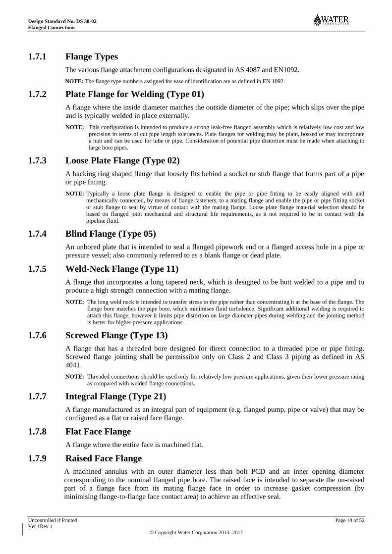
1.7.1 Flange Types
The various flange attachment configurations designated in AS 4087 and EN1092.
NOTE: The flange type numbers assigned for ease of identification are as defined in EN 1092.
1.7.2 Plate Flange for Welding (Type 01)
A flange where the inside diameter matches the outside diameter of the pipe; which slips over the pipe
and is typically welded in place externally.
NOTE: This configuration is intended to produce a strong leak-free flanged assembly which is relatively low cost and low
precision in terms of cut pipe length tolerances. Plate flanges for welding may be plain, bossed or may incorporate
a hub and can be used for tube or pipe. Consideration of potential pipe distortion must be made when attaching to
large bore pipes.
1.7.3 Loose Plate Flange (Type 02)
A backing ring shaped flange that loosely fits behind a socket or stub flange that forms part of a pipe
or pipe fitting.
NOTE: Typically a loose plate flange is designed to enable the pipe or pipe fitting to be easily aligned with and
mechanically connected, by means of flange fasteners, to a mating flange and enable the pipe or pipe fitting socket
or stub flange to seal by virtue of contact with the mating flange. Loose plate flange material selection should be
based on flanged joint mechanical and structural life requirements, as it not required to be in contact with the
pipeline fluid.
1.7.4 Blind Flange (Type 05)
An unbored plate that is intended to seal a flanged pipework end or a flanged access hole in a pipe or
pressure vessel; also commonly referred to as a blank flange or dead plate.
1.7.5 Weld-Neck Flange (Type 11)
A flange that incorporates a long tapered neck, which is designed to be butt welded to a pipe and to
produce a high strength connection with a mating flange.
NOTE: The long weld neck is intended to transfer stress to the pipe rather than concentrating it at the base of the flange. The
flange bore matches the pipe bore, which minimises fluid turbulence. Significant additional welding is required to
attach this flange, however it limits pipe distortion on large diameter pipes during welding and the jointing method
is better for higher pressure applications.
1.7.6 Screwed Flange (Type 13)
A flange that has a threaded bore designed for direct connection to a threaded pipe or pipe fitting.
Screwed flange jointing shall be permissible only on Class 2 and Class 3 piping as defined in AS
4041.
NOTE: Threaded connections should be used only for relatively low pressure applications, given their lower pressure rating
as compared with welded flange connections.
1.7.7 Integral Flange (Type 21)
A flange manufactured as an integral part of equipment (e.g. flanged pump, pipe or valve) that may be
configured as a flat or raised face flange.
1.7.8 Flat Face Flange
A flange where the entire face is machined flat.
1.7.9 Raised Face Flange
A machined annulus with an outer diameter less than bolt PCD and an inner opening diameter
corresponding to the nominal flanged pipe bore. The raised face is intended to separate the un-raised
part of a flange face from its mating flange face in order to increase gasket compression (by
minimising flange-to-flange face contact area) to achieve an effective seal.

Design Standard No. DS 38-02
Flanged Connections
Uncontrolled if Printed Page 11 of 52
Ver 1Rev 1
© Copyright Water Corporation 2013- 2017
A raised face flange enables higher gasket sealing pressures for a given fastener force as compared
with a flat face flange that has a full face gasket.
1.7.10 Full Face Gasket
A gasket with an outside diameter equal to the flange outside diameter.
1.7.11 Narrow Face Gasket
A gasket with an outside diameter equal to the diameter of the raised flange face (or inside of the bolt
circle).
1.7.12 O-ring Gasket
An elastomeric ring which fits into a machined groove in the flange face.
NOTE: O-rings flange gaskets are not permissible arising from past operational experience of corrosion in the vicinity of
the wetted side of O-ring grooves and from field joint preparation/assembly quality. The use of narrow face
compressed fibre gaskets is preferred in applications where O-ring gaskets have been used in the past.
1.7.13 Segmented Gasket
A flat gasket that comprises an assembly of interlocking gasket segments rather than a single integral
sheet of gasket material.
NOTE: Segmented flange gaskets are not permissible except where expressly authorised in writing on the basis of
demonstrated project justification including consideration of service longevity and failure risks.
1.7.14 Flange Fasteners
Bolts, nuts and washers used in the assembly of flanged pressure retaining components (pipes).
1.7.15 Structural Fasteners
Bolts, nuts and washers used in the assembly of structural components (non-pressure retaining
components).
NOTE: The selection and use of structural fasteners shall be in accordance with requirements and guidance provided in the
“Fasteners and Washers” section of DS 30-02 and in the “Bolting Structural Joints” section of DS 38-01.
1.7.16 Galling
The adhesive wear and propagation of damage between the bearing surface of a nut or bolt head, and
its mating surface in a fastener application. This can cause a significant increase in resistance during
tightening resulting in a lower induced tension in the fastener, a lower clamping force on the gasket
and consequently a greater chance of joint leakage.
1.8 Acronyms and Symbols
For acronyms and symbols referred to in this Standard the reader is referred to that section contained in
DS 30-01.
1.9 Standard Units and Relationships
The units and relationships used for mechanical designs shall be in accordance with those specified in
the SI Units, Relationships, and Prefixes section of DS 30-01.
1.10 Drawing Symbols
A comprehensive list of mechanical drawing symbols is referenced in DS 80.

Design Standard No. DS 38-02
Flanged Connections
2 DESIGN
2.1 Pressure Ratings
The flange connection pressure rating shall typically equal or exceed the pressure rating of a flanged
piping system. Where equipment is procured of higher pressure rating, the equipment and pipe work
flanges shall match the equipment pressure rating. Flange pressure ratings shall be selected from the
following subject to the conditions outlined below:
Pressure classes: PN 6, PN 10, PN 16, PN 21, PN 25, PN 35, PN 40
NOTE: Corporation non-preferred pressure ratings are shown in italics.
Subject to Corporation acceptance, pressure ratings PN 6, PN 10, PN 25 and PN 40 shall be limited to
the following applications:
(a) PN 6 rated flanges may be used on nominal low or non-pressure (usually large diameter)
applications e.g. typical of wastewater inlets, treatment plants and storage tank inlets.
(b) PN 10 rated flanges may be used in special low pressure applications e.g. water and wastewater
treatment plants.
(c) PN 25 and PN 40 rated flanges may need to be considered for special pressures in certain
circumstances.
2.2 Designation of Flange Standards
Flange specifications, within the applicable sizes and pressure ratings, shall comply with AS 4087
except as stated below:
(a) Flange diameters and/or pressures beyond the scope of AS 4087 shall comply with the
requirements of EN 1092 or Corporation independently verified flange specifications (based on
EN 1092). Refer to Table 2.1 for an outline of the available complete flange designs and
specifications (drill pattern and thickness) of the relevant flange standards.
(b) Where proprietary equipment is unavailable with AS 4087 flanges, the mating flange shall
match the equipment flange specification.
(c) The selection and use of AS 2129 Table E flange specifications shall be limited to the following
applications:
General purpose tapped lugged butterfly valves
General purpose valves and appurtenances of sizes less than DN 80
NOTE: EN 1092 and AS 4087 flanges are not compatible.

Design Standard No. DS 38-02
Flanged Connections
Uncontrolled if Printed Page 13 of 52
Ver 1Rev 1
© Copyright Water Corporation 2013- 2017
Table 2.1 –Flange Specification Selection Synoptic Table – Steel Flanges
Flange Description
Type
Relevant
Standard
DN
PN
50
65
80
10
0
15
0
20
0
25
0
30
0
35
0
40
0
45
0
50
0
60
0
70
0
75
0
80
0
90
0
10
00
12
00
14
00
16
00
18
00
20
00
Pla
te
(Pre
ferr
ed e
xcep
t w
her
e
dem
on
stra
bly
una
vail
able
)
01
EN 1092 6 x x x x x x x x x x x x x x x x x x x x x x
EN 1092 10 ↓16 ↓16 ↓16 ↓16 ↓16 x x x x x x x x x x x x x
EN 1092 16 x x x x x x x x x x x x x x x x x x x x x x
AS 4087 16 x x x x x x x x x x x x x x x x x x x
AS 4087 21 x x x x x x x x x x x x x x x x x x x
EN 1092 25 ↓40 ↓40 ↓40 ↓40 ↓40 x x x x x x x x x
x w w w w
AS 4087 35 x x x x x x x x x x x x x x x x x x x
EN 1092 40 x x x x x x x x x x
Bla
nk
(Dea
d P
late
)
05
EN 1092 6 x x x x x x x x x x x x x x x x x x x x x x
EN 1092 10 ↓16 ↓16 ↓16 ↓16 ↓16 x x x x x x x x x x x x x
AS 4087 16 x x x x x x x x x x x x x x x x x x x
AS 4087 21 x x x x x x x x x x x x x x x x x x x
EN 1092 25 ↓40 ↓40 ↓40 ↓40 ↓40 x x x x x x x x x
AS 4087 35 x x x x x x x x x x x x x x x x x x x
EN 1092 40 x x x x x x x x x x x x x
Wel
d N
eck
(Use
wher
e pla
te d
emonst
rably
un
ava
ilable
or
impra
ctic
able
,
e.g.
Cla
use
2.6
)
11
EN 1092 6 x x x x x x x x x x x x x x x x x x x x x x
EN 1092 10 ↓16 ↓16 ↓16 ↓16 ↓16 x x x x x x x x x x x x x x x x x
EN 1092 16 x x x x x x x x x x x x x x x x x x x x x x
AS 4087 16 x x x x x x x x x x x x x x x x x x x
AS 4087 21 x x x x x x x x x x x x x x x x x x x
EN 1092 25 ↓40 ↓40 ↓40 ↓40 ↓40 x x x x x x x x x x x x w w
AS 4087 35 x x x x x x x x x x x x x x x x x x x
EN 1092 40 x x x x x x x x x x x x x w w w w w w
Inte
gra
l
21 EN 1092 6 x x x x x x x x x x x x x x x x x x x x x x
EN 1092 10 ↓16 ↓16 ↓16 ↓16 ↓16 x x x x x x x x
EN 1092 16 x x x x x x x x x x x x x x x x x x x x x x
AS 4087 16 x x x x x x x x x x x x x x x x x x x
AS 4087 21 x x x x x x x x x x x x x x x x x x x
EN 1092 25 ↓40
↓40
↓40
↓40
↓40
x x x x x x x x
AS 4087 35 x x x x x x x x x x x x x x x x x x x
EN 1092 40 x x x x x x x x x x x x x
LEGEND: Flange sizes in bold are preferred
x – Drill pattern and thickness specification available in standard
w – See Corporation flange specification for thickness details – refer Clause 2.5
↓16 – Use PN16 EN1092 flange dimensions
↓40 – Use PN40 EN1092 flange dimensions

Design Standard No. DS 38-02
Flanged Connections
Uncontrolled if Printed Page 14 of 52
Ver 1Rev 1
© Copyright Water Corporation 2013- 2017
2.3 Flange Types
The following flange types (as designated in EN 1092) are acceptable to the Corporation:
Type 01 Plate flange for welding
Type 02 Loose plate flange
Type 05 Blind flange
Type 11 Weld-neck flange
Type 13 Screwed Flange
Type 21 Integral flange
The type of flange to be used shall be specified and designed by the Designer. The flange design shall
be cost effective, shall be constructible; and shall be compatible with the mating equipment and
pipework.
2.4 Flange Facing
The facing requirements for each flange shall be specified and designed by the Designer to ensure
mating flange compatibility and to achieve the required compression joint type (flat face or narrow
face joint).
The following limitations on flange face types shall be take into consideration by the Designer:
2.4.1 Flat Face Flanges
Grey cast iron flanges shall be flat faced in accordance with AS 4087 and shall be mated only with
other flat faced flanges. Grey cast iron flanges in accordance with EN 1092.2 shall not be permissible1.
Mating flanges shall be flat faced where either flange is of a brittle material (e.g. grey cast iron, PVC-
U, ABS) in order to mitigate the potential for bolting couples due to rotation and consequent cracking
of the brittle material during flange fastener tightening, where flange faces are raised.[JP1]
NOTES:
1. Raised face configuration of grey cast iron flanges EN 1092.2 Clauses 5.3 and 5.7.1 renders them unsuitable for
Corporation flange applications.
2. PVC-M, PVC-U and ABS flange connections are non-preferred but, where required and justified, shall be fitted with
hot dip galvanised steel or Gr 316 stainless steel backing flanges with pre-drilled holes complying with AS 4087.
2.4.2 Raised Face Flanges
Where a raised face flange is used, both mating flanges shall be comprised of a ductile material (e.g.
steel, ductile cast iron).
The raised faces of mating flanges shall be restricted to ductile materials for reasons outlined in
Section 2.4.1.
2.5 Corporation Designed Flanges
The Corporation has undertaken design in accordance with EN 1951-1:2001 to establish flange
thickness requirements for particular large diameter high pressure flanges to EN 1092 specification.
Refer to Table 2.2 below for a summary of available Corporation designed flanges.
In the event of an overlap or conflict between EN 1092 and Corporation designed flange
specifications, the Corporation designed flange specification shall prevail.

Design Standard No. DS 38-02
Flanged Connections
Uncontrolled if Printed Page 15 of 52
Ver 1Rev 1
© Copyright Water Corporation 2013- 2017
Table 2.2 – Corporation Designed Flanges
Flange Type Size (DN) Material2
Drg Number
PN 25 Raised face slip-on 900 – 1400 AS/NZS 3678 Gr250 JZ39-91-4
PN 25 Flat face slip-on 700 – 1400 AS/NZS 3678 Gr250 JZ39-91-5
PN 25 Raised face weld
neck
1200 – 1400 ASTM A350 LF3
(Carbon Steel Forging)
AS 1448 GrK5
(equivalent)
JZ39-91-6
PN 25 Flat face weld neck 700 – 1400 ASTM A350 LF3
(Carbon Steel Forging)
AS 1448 GrK5
(equivalent)
JZ39-91-7
PN 40 Raised face weld
neck
700 – 1400 ASTM A350 LF3
(Carbon Steel Forging)
AS 1448 GrK5
(equivalent)
JZ39-91-9
NOTE: The above flange specifications have been derived on the basis of carbon steel of material grade 250 MPa or higher.
Flanges to AS and EN specifications are based on the use of lower grade (typically grade 200 MPa) material. This
has resulted in relatively lower thickness flange specifications in Corporation designed flanges.
2.6 Seal on Body Butterfly Valve Joint Sealing
The Designer shall consider the required sealing internal diameter (ID) for the purpose of specifying
requirements for seal on body butterfly valve mating flange and associated weld details.
The mating flange requirements for Wouter Witzel and Ebro seal on body butterfly valves are
respectively shown in Table 2.3 and Table 2.4. Each table indicates the maximum permissible internal
diameter of the mating flanges (to ensure sealing of the flange face) and minimum permissible
pipeline internal diameter (to avoid disc fouling), as specified by the valve manufacturer.
Where a valve requires the mating pipe flange ID to match that of the adjoining pipework, either a
weld neck flange or standard alternative plate flange butt weld preparation shall be used.
The use of gaskets for the purpose of flange joint sealing is not recommended by Manufacturers of
seal on body valves as the supplied valve is intended to provide the seal.
Figure 2.1. Typical pipe flange to seal on body butterfly valve sealing arrangements.
A
Slip-on flange to butterfly valve typical
arrangement.
B
Butt welded plate flange to butterfly valve
typical arrangement.

Design Standard No. DS 38-02
Flanged Connections
Uncontrolled if Printed Page 16 of 52 Ver 1 Rev 1 © Copyright Water Corporation 2013-2017
Table 2.3 Seal on Body Butterfly Valve Mating Flange Requirements – Wouter Witzel Series 75 (EVFS)
* Non compatible HDPE pipe, including all PN16 pipe, requires a proprietary butterfly valve spacer to avoid disc interference.
Minimum mating flange or cement lining internal diameter to avoid disc interference Maximum mating flange internal diameter to achieve a leak tight seal
DN
Minimum
allowable (as
specified by
Wouter Witzel)
MSCL Pipe (in
accordance with DS
60)
MSCL welded
flange AS 4087
PN16 and PN21
HDPE Pipe (PN12.5
SDR 13.5) with stub
flange and backing
ring.
Maximum allowable
(as specified by
Wouter Witzel)
MSCL butt
welded/weldneck
flange (sealing face
ID “B” mm)
MSCL/SS slip on
flange (sealing
face ID “A” mm)
SS butt welded/weldneck
flange Sch10 (sealing
face ID “B” mm)
ID (PN16 and
PN21)
ID
(mm)
ID with
cement
lining
(mm)
ID
(mm)
Accept-
table
ID
(mm)
Accept-
able
ID
(PN16)
ID
(PN21) ID (mm)
Accept-
able
ID
(mm)
Accept-
able ID (mm)
Accept-
able
400 320 396 372 372 OK 335 OK 420 420 396 OK 409 OK 393.7 OK
500 429 498 474 474 OK 418.8 NO* 529 529 498 OK 511 OK 495.3 OK
600 522 598 574 574 OK 527.8 OK 626 626 598 OK 613 OK 597.3 OK
700 621 699 675 675 OK 594.8 NO* 730 730 699 OK 714 OK 698.3 OK
800 719 799 767 767 OK 670.4 NO* 834 844 799 OK 816 OK 797.16 OK
900 823 900 868 868 OK 754 NO* 954 944 900 OK 917 OK 898.16 OK
1000 897 1000 968 968 OK 840 NO* 1035 1047 1000 OK 1019 OK 1000.16 OK
1200 1089 1201 1164 1164 OK 1005.6 NO* 1250 1266 1201 OK 1222 OK 1203.16 OK
1400 1281 1400 1360 1360 OK 1173.4 NO* 1460 1480 1400 OK 1425 OK

Design Standard No. DS 38-02
Flanged Connections
Uncontrolled if Printed Page 17 of 52 Ver 1Rev 1
© Copyright Water Corporation 2013- 2017
Table 2.4 Seal on Body Butterfly Valve Mating Flange Requirements – EBRO F012-A
* Non compatible HDPE pipe, including all PN16 pipe, requires a proprietary butterfly valve spacer to avoid disc interference.
Minimum mating flange or cement lining internal diameter to avoid disc interference Maximum mating flange internal diameter to achieve a leak tight seal
DN
Minimum
allowable (as
specified by
EBRO)
MSCL Pipe (in
accordance with
DS 60)
MSCL welded flange
AS 4087 PN16 and
PN21
HDPE Pipe (PN12.5
SDR 13.5) with stub
flange and backing
ring.
Maximum
allowable (as
specified by
EBRO)
MSCL butt
welded/weldneck
flange (sealing face
ID “B” mm)
MSCL/SS slip on
flange (sealing face
ID “A” mm)
SS butt
welded/weldneck
flange Sch10 (sealing
face ID “B” mm)
ID (PN16 and
PN21)
ID
(mm)
ID with
cement
lining
(mm)
ID
(mm)
Accept-
table
ID
(mm)
Accept-
able
ID (PN16 and
PN21)
ID
(mm)
Accept-
able
ID
(mm)
Accept-
able ID (mm)
Accept-
able
400 332 396 372 372 OK 335 OK 412 396 OK 409 OK 393.7 OK
500 442 498 474 474 OK 418.8 NO* 514 498 OK 511 OK 495.3 OK
600 527 598 574 574 OK 527.8 OK 615 598 OK 613 OK 597.3 OK
700 618 699 675 675 OK 594.8 NO* 720 699 OK 714 OK 698.3 OK
800 723 799 767 767 OK 670.4 NO* 824 799 OK 816 OK 797.16 OK
900 829 900 868 868 OK 754 NO* 930 900 OK 917 OK 898.16 OK
1000 903 1000 968 968 OK 840 NO* 1030 1000 OK 1019 OK 1000.16 OK
1200 1093 1201 1164 1164 OK 1005.6 NO* 1230 1201 OK 1222 OK 1203.16 OK
1400 1283 1400 1360 1360 OK 1173.4 NO* 1430 1400 OK 1425 OK

Design Standard No. DS 38-02
Flanged Connections
Uncontrolled if Printed Page 18 of 52 Ver 1 Rev 1 © Copyright Water Corporation 2013-2017
2.7 Flanged Joint Selection
The Designer shall nominate the required flange and gasket combination to achieve the necessary
gasket compression joint type (full face or narrow face joint). Provision shall be made for:
practicability and ease of installation;
flange face limitations as given in Clause 2.4;
size and pressure rating (PN) limitations as given below in Table 2.5 (based on AS 4087 Table
C1).
The following flange and gasket combinations may apply as appropriate:
2.7.1 Full Face Joint
(a) Flat face to flat face with a full face gasket.
(b) Blank flange with a bonded full surface gasket1.
2.7.2 Narrow Face Joint
(a) Flat face to raised face flange with a full face gasket.
(b) Raised face to raised face flange with a full face gasket.
(c) Flat face to flat face flange with a narrow face gasket2, 3
.
(d) Flat face flange to seal on body valve flange face with integral valve liner providing the seal.
NOTES: 1. The bonded full surface gasket of a blank flange is intended to prevent flange face corrosion.
2. Not a preferred joint due to gasket installation practicability.
3. Narrow face gaskets are not permissible where an isolating joint is required (refer Clause 2.11 of this Standard).

Design Standard No. DS 38-02
Flanged Connections
Uncontrolled if Printed Page 19 of 52
Ver 1Rev 1
© Copyright Water Corporation 2013- 2017
Table 2.5 – Flanged Joint size, Pressure Rating and Gasket Material.
DN
Pressure Class
DN PN 6/10 PN 14/16 PN 21/25/35/40
2000
FULL-FACE
JOINT
ELASTOMERIC
GASKET
2000
1800 1800
1600 1600
1400 1400
1200 1200
1000 1000
900 900
800 800
700 700
600 600
500 500
400 400
300 300
250
250
200 200
100 100
80 80
65 65
50 50
NOTE: Flange size (DN) relates to the line above the numeric value e.g. PN14/16 full-face elastomeric gasket joint extends
to DN 300.
2.8 Gasket Material Selection
Gasket materials to be used for new flange connections within the Corporation shall be either:
(a) Elastomeric; or
(b) Compressed fibre.
Guidance on flange O-rings is included in this Standard as they exist in Corporation systems. It is not
intended to modify existing flanged sealing arrangements retrospectively.
The Designer shall nominate the required gasket material with respect to flange size and pressure
rating in accordance with Table 2.5 and the following material requirements.
When bolting to proprietary equipment the gasket material to be used shall be as specified by the
equipment Manufacturer. In the case of magnetic flow meters, guidance on gasket material is
provided at Section 2.11 and limited assembly information is provided in Section 5 Appendix A -
Bolting Torques (Informative).
For problematic joints where low torque gaskets are required (eg. Mag flow meters or PE pipe) the use
of proprietary gaskets (eg. SURESEAL “Maxi”) may be considered in consultation with the
equipment manufacturer.
NARROW FACE JOINT
COMPRESSED
FIBRE GASKET

Design Standard No. DS 38-02
Flanged Connections
Uncontrolled if Printed Page 20 of 52
Ver 1Rev 1
© Copyright Water Corporation 2013- 2017
2.8.1 Elastomeric Gaskets
Elastomeric gaskets for applications that do not involve exposure to hydrocarbons shall be EPDM (UV
stabilised)1, silicon gaskets may be used for isolated joint applications as indicated in Section 2.11.
NBR (nitrile butadiene rubber) gaskets shall be used for high hydrocarbon content applications.
Gaskets for contact with chemicals and gases shall be selected in accordance with the appropriate
resistance characteristics for the particular process chemical, or gas. Gaskets likely to be exposed to
gaseous chlorine or chlorine solution shall be FPM (fluoroelastomer polymer, e.g. Viton).
Natural rubber gasket shall not be used as it is known to be adversely affected by microbial growth.
NOTES: 1. EPDM can deteriorate from exposure to sewage or sludge with high levels of hydrocarbons, as the elastomer
carbon content is unlikely to ensure appropriate isolation (especially when compressed).
2. The use of elastomeric rather than compressed fibre material for flange gaskets in smaller pipeline size and lower
pressure applications offers advantages in terms of cost, availability and ease of field usage.
3. Further elastomer application requirements and guidance are given in DS 30-02, Section 33 ‘Materials -
Elastomers’.
2.8.2 Reinforced Elastomeric Gaskets
The use of elastomeric gaskets incorporating a reinforcing fabric shall be limited to applications where
fluid loss by means of ‘wicking’ is unlikely (i.e. full face gaskets on blank flanges or access covers).
NOTE: The use of annular reinforced fabric gaskets can lead to ‘wicking’ (i.e. leakage of water along paths provided by the
fabric) through the inside cut edge to the outside environment’.
2.8.3 Compressed Fibre Gaskets
Compressed fibre gaskets shall be of material equivalent to Novus 30 or Klinger C4430.
Compressed fibre gaskets with a high elastomer content (e.g. Klinger C6327 or equivalent) may be
used for blank flanges or access covers to assist gasket compression and sealing of the joint.
NOTES: 1. Compressed fibre gasket material has low compressibility at high load and is likely to minimise gasket seating area
leakage potential that may arise due to gasket surface indentations.
2. The Corporation has adopted the use of compressed fibre gaskets to overcome previously unsatisfactory O-ring seal
performance and has accordingly supported their inclusion in AS 4087–2004

Design Standard No. DS 38-02
Flanged Connections
Uncontrolled if Printed Page 21 of 52
Ver 1Rev 1
© Copyright Water Corporation 2013- 2017
2.9 Fasteners
Fastener materials to be used for flange connections shall be either:
(a) Hot dip galvanized carbon steel, or
(b) Stainless steel.
Fasteners are be supplied in accordance with Table 2.6. For hot dip galvanized carbon steel bolting in
sizes M12 to M36, AS1252.1 is preferred due to lower cost and higher availability. AS1110.1 bolting
is only available as standard in plain finish and must be galvanized.
Note: Cost comparison AS110.1 vs AS1252.1 bolting may be found at Aqua #17333576.
Bolts, nuts and washers shall be of the same material type within the flanged joint. Where two or
more materials are used, (eg. one galvanised flange face bolted onto a stainless steel flange face),
electrical isolation using isolation flange kits shall be provided. Particular attention shall be paid to
ensure that there is no direct electrical contact between two dissimilar metals (eg. mild steel washers
used with stainless steel bolts).
The use of black bolts is not preferred due to susceptibility to corrosion over time and shall not be
allowed except by permission of the Principal Engineer.
The use of threaded bar is not preferred, and shall only be allowed by permission of the Principal
Engineer where it is not physically possible to install bolts or where bolt availability will impact the
project schedule. Where threaded bar is to be used, it shall be property class 8.8 and material
certificates detailing the mechanical and chemical properties of the bar material shall be supplied.
Cold galvanizing of threaded bar shall not be allowed, bar is to be procured black, cut to length and
then hot dip galvanized. “8.8” shall be stamped on both ends of the bar for identification purposes
prior to galvanizing. AS1252.1 nuts & washers shall be used with threaded bar.
The Designer shall nominate the required fastener material and property class for each flange
connection. Relevant fastener standards are referenced below in Table 2.7 for carbon steel and
stainless steel fastener components.
Table 2.6 – Typical fastener material applications
Application Fastener material
Dry Internal, e.g. Pump Station Hot Dipped Galvanised
Damp Internal Stainless Steel Gr316
External – Non-coastal Hot Dipped Galvanised
External – Coastal Stainless Steel Gr316
Waste Water Treatment Plant – External Hot Dipped Galvanised
Waste Water Treatment Plant – Open Channel Stainless Steel Gr316
Buried Hot Dipped Galvanised, wrapped
Process Plant - chemicals Stainless Steel Gr316
Waste Water Pump Station – Wet Well Stainless Steel Gr316

Design Standard No. DS 38-02
Flanged Connections
Uncontrolled if Printed Page 22 of 52
Ver 1Rev 1
© Copyright Water Corporation 2013- 2017
Table 2.7 – Fasteners Standard requirements
PC(1)
Dimensions Mechanical Properties HD Galvanized
Standard Size
Standard / Hardness Size(2)
Standard Size
Bolt:
8.8 AS 1252.1(7)
M12 to M36 AS 4291.1 M12 to M36 AS 1214 M12 to
M36
8.8 AS 1110.1 ≤ M64
AS 4291.1 ≤ M64 AS 1214 ≤ M64
A4-70
(316SS) AS 1110.1
≤ M30
ISO 3506-1
≤ M30 N/A N/A
A4-80
(316SS) >M30≤M64 ≤ M64 N/A N/A
Nut:
8 AS 1252.1(7)
M12 to M36 AS4291.2 M12 to M36 AS 1252.1 M12 to
M36
8 AS 1112.1 ≤ M64 AS/NZS 4291.2 ≤ M64 AS 1214 ≤ M64(3)
A4-70
(316SS) AS 1112.1
≤ M30 ISO 3506-2 ≤ M30 N/A N/A
A4-80
(316SS) >M30≤ M64 ISO 3506-2 ≤ M64 N/A N/A
Flat Washers:
(5) AS 1252.1 M12 to M36 320 – 390HV
(1) M12 to M36
AS/NZS
4680
M12 to
M36
(6) AS 1237.1
AS 1237.2 (4)
Dia < 39mm
thickness < 6mm 300HV
(1 ) ID < 39mm
AS/NZS
4680 ≤ M64
Dia ≥ 39mm
thickness > 6mm 100HV
(1) ID ≥ 39mm
A4
(316SS) AS 1237.1 < M64 ISO 7089 / 200HV < M64 N/A N/A
NOTE:
1. PC refers to property class; HV refers to hardness (Vickers).
2. Bolts > M39 apply to EN 1092 e.g. for PN 25 > DN 700 and PN 40 > DN 500.
3. Nuts to AS1112.1 shall be tapped oversize after galvanizing to accommodate added coating thickness of bolt.
4. AS 1237.2 specifies acceptable washer dimensional tolerances
5. AS 1252.1 washers shall be used with AS 1252.1 bolting.
6. AS 1237.1 washers shall be used with AS 1110.1 & AS 1112.1 bolting.
7 The head on AS1252.1 nuts and bolts is physically larger than for other listed bolting, the designer / contractor will
need to confirm that clearances between the bolt head or nut and the wall of the pipe / valve will be adequate to fit a
socket and spanner for assembly.

Design Standard No. DS 38-02
Flanged Connections
Uncontrolled if Printed Page 23 of 52
Ver 1Rev 1
© Copyright Water Corporation 2013- 2017
2.9.1 Hot-Dip Galvanised Fasteners
The Designer shall consider the potential for galling of hot dip galvanised bolts, and the resulting
higher torques and bolt relaxation when specifying bolt torques for proprietary items of equipment.
2.9.2 Stainless Steel Fasteners
Stainless steel fasteners shall comply with Table 2.7.
The Designer shall address the potential for galling between stainless steel fastener mating threads by
either the use of:
(a) different grade bolts and studs to the nuts where available; or
(b) anti-seize compounds where similar grade mating threads are used. (Refer Clause 4.5 of this
Standard)
The hardness of stainless steel nuts and washers should differ by at least 50 Brinell wherever
practicable and available.
Stainless steel fasteners, where used to bolt to a dissimilar material, shall be insulated by fitting:
(a) G10 washers under stainless steel washers; and
(b) phenolic sleeves around each individual bolt.
2.9.3 Fasteners for Tapped Holes
When mating to a tapped flange the Designer shall specify bolts and washers that are either:
(a) Stainless steel.
(b) Galvanised Steel (refer Note)
(c) Black carbon steel bolts (petrolatum tape wrapped) for buried-service.
(d) Black bolts (painted) for above ground service.
Where black bolts are used above-ground and corrosion is of concern (moisture laden environments),
corrosion mitigation measures such as protective bolt head covers or petrolatum tape wrapping of the
flange shall be applied.
NOTE: Problems can occur in fitting hot-dip galvanised bolts or stud bolts into tapped holes in proprietary products
because of the coating on the threads e.g. tapped holes in butterfly valves. Under these circumstances hot-dip
galvanised fasteners cannot be readily fitted without modification e.g. oversize tapping of the holes,
requirement need to be discussed with product manufacturers and requirement included in procurement
specification.
2.9.4 Fastener Torquing
The Designer shall consider that the nut as the preferred fastener component to be rotated during
tightening when designing flange connections. This may not always be practicable for sites where
access for torque wrench operation is constrained (restricted).
Bolt torque values shall be specified as lubricated values. (Refer to Appendix A)
The bolts shall be specified to be lightly oiled, in order to reduce the bolting friction co-efficient in the
order of µ = 0.1 - 0.2. (Refer to Section 4.5)
NOTE: Lubrication is required to reduce bolting frictional resistance, increase the induced fastener tension, and
improve the clamping force. A 10% frictional reduction from lubrication could increase induced tension by 80-
90%.
When bolting to proprietary equipment such as magflowmeters and seal on body butterfly valves, the
Designer shall establish appropriate bolt torques in consultation with the equipment Manufacturer.
Limited informative torques / assembly information is provided in Section 5 Appendix A - Bolting
Torques (Informative).

Design Standard No. DS 38-02
Flanged Connections
Uncontrolled if Printed Page 24 of 52
Ver 1Rev 1
© Copyright Water Corporation 2013- 2017
NOTE: Applying bolt torques greater than that recommended by the Manufacturer may damage the equipment and void the
equipment warranty.
2.10 Washers
Hot-dip galvanised steel washer faces shall be specified with a smooth finish. One washer shall be
fitted under the bolt and one washer under the nut for each flanged joint.
NOTE: Two washers are required for each fastener for all applications in the interest of simplification e.g. rather than
having to consider whether the bolt head or nut will be the turned item, or whether coating protection is
required.
2.11 Isolation Joints
Isolation flange joints shall be required for:
Electrical isolation of sections of pipelines where cathodic protection is to be employed.
Isolation of instrumentation such as magnetic flow meters.
Isolation of galvanically dissimilar materials e.g. stainless steel and hot dipped galvanised steel.
NOTES:
1. Refer to standard drawing JZ39-91-10 for all isolation flange connection details and DS 91 for further information on
cathodic protection. Elastomeric isolating gaskets shall be used with magnetic flow meters, refer to Section 2.11.1
2. Bolt torques for magnetic flow meters are typically low (refer Section 5.5) and the use of compressed fibre gaskets
will not generally be possible.
3. For all joint types each hole shall be spot faced on the back face surface to prevent the insulating washer from ripping
during bolt tightening.
4. Isolation against a magnetic flow meter shall be in accordance with the Manufacturer’s recommendations.
2.11.1 Insulating Gaskets
In order to maintain the insulated joint integrity, full face gaskets shall be fitted to all insulated joint
types, regardless of whether flat or raised face flanges are used. The gasket shall be 3mm thick
compressed material such as the Klinger C-4430, Novus HDS-1, or equivalent. The dielectric strength
of the gasket shall be at least 15.2kV/mm (wet and compressed).
Where providing isolation (eg. for dissimilar metals, cathodic protection etc.) and an elastomeric
gasket is required, then it may be used provided it can be proven the material is non-conductive (nb.
EPDM potable will likely not be suitable due to graphite being added to the material).
Limited trials conducted on PN16 magnetic flow meters indicates that Novus Red Silicon (60 Duro)
rubber sheet gasketing is a suitable elastomeric material, which has potable water approval and is non-
conductive.
NOTES:
1. It is expected that further trialing of Novus Red Silicon will confirm the suitability of this material for higher pressure
mag flow meters. At that time this section of the standard will be revised.
2. For sealing of magnetic flow meters, it is important that the joint detail as per JZ39-91-10 be applied as appropriate
for the body liner material.
2.11.2 Insulating Kits
Flange cathodic protection isolation shall be achieved by the use of Klinger, Novus or Savcor
insulating flange kits (or approved equivalent), and installed in accordance with the Manufacturer’s
recommendations. A flange insulating kit includes:
Insulating gasket
One full length insulating sleeve per bolt
Two insulating washers per bolt

Design Standard No. DS 38-02
Flanged Connections
Uncontrolled if Printed Page 25 of 52
Ver 1Rev 1
© Copyright Water Corporation 2013- 2017
The insulating sleeve material shall be polyester resin (Mylar or equivalent). It shall be sized to fit the
entire length of the exposed fastener in the joint. The insulating washer material shall be G10 glass
epoxy laminate.
2.11.3 Cathodic Protection Isolation Test Points
Insulated flange test points shall be provided on flanged isolation joints in accordance with LL33-54-
4.

Design Standard No. DS 38-02
Flanged Connections
Uncontrolled if Printed Page 26 of 52
Ver 1Rev 1
© Copyright Water Corporation 2013- 2017
3 MANUFACTURING REQUIREMENTS This section covers manufacturing requirements relating to flanges and flange fasteners. The Designer
shall detail all requirements relevant to flange manufacture, material specifications, and joint
configuration details.
3.1 Flanges
Flanges shall be manufactured in accordance with the requirements contained in the relevant standard
(AS 4087 or EN 1092 as applicable) except where varied in accordance with the following:
3.1.1 Ultrasonic Testing of Large Flanges
Ultrasonic test acceptance shall comply with AS 1710 Table 5.2 for steel flanges and AS 2574 Level 2
for ferritic steel castings.
For pressure ratings greater than PN16, DN 500 and larger flanges shall be subject to ultrasonic testing
after manufacture to check for laminations.
3.1.2 Tolerances
Flange face flatness shall comply with the relevant standard (AS 4087 or EN 1092 as applicable) after
fabrication. The flanges shall be perpendicular to the pipe centerline within 0.25º or 2mm (at the
outside diameter) whichever is the lesser. Any distortion shall be corrected by machining.
Flanges shall be drilled and fitted off-centre. Bolt holes shall comply with AS 4087 (or EN 1092 as
applicable), and shall be drilled parallel to the axis of the flange. If the rake angle is greater than 2°,
the backs of all flanges shall be machined or each hole spot faced to provide a satisfactory bearing for
bolt heads and nuts. Machining or spot facing shall not reduce the flange thickness to less than the
minimum required flange thickness specified.
3.1.3 Sealing Surface
The contact surface shall be whip blasted, and given a gramophone finish within the roughness range
of 6.3µm to 3.2µm.
NOTE: If the serrations were to exceed 6.3µm as given in AS 4087, there is the possibility that the serrations could cut too
deeply into the surface of a gasket which could ultimately result in premature failure of the gasket.
3.1.4 Face Coating
A thin layer of anticorrosive coating such as Lanotec Type A grease shall be applied to flange faces
after welding and machining. The gasket face coating shall be removed prior to flange installation.
Where epoxy coatings are applied to the flange non-sealing surface, the protective coating thickness
shall be 80 – 250µm.
NOTE: Epoxy coating over a machined flange face gramophone finish is not recommended as this may result in poor or
non-leak tight sealing.
3.2 Gaskets
Gasket dimensions shall be as required by the relevant flange product standard e.g. AS 4087 or EN
1092 (which references EN 1514 for gasket types), except where varied by this Standard. Refer to
Table 3.1 for a summary of required gasket properties and reference manufacturing standards.
The nominal thickness of narrow face compressed fibre gaskets for pressure ratings ≥ PN25 may be
increased to 3mm where required to compensate for inherent flange face irregularities.
Gaskets shall be dimensioned such that the ID does not protrude into the bore of the pipe.

Design Standard No. DS 38-02
Flanged Connections
Uncontrolled if Printed Page 27 of 52
Ver 1Rev 1
© Copyright Water Corporation 2013- 2017
Table 3.1 Gasket Material and Size Requirements
Item Standard Material Thickness
mm
Nominal Hardness
Elastomeric
gasket
AS 1646
AS 4087
EN 1092
WSA 109
NBR, EPDM, Viton 3 55 – 75
IRHD
Compressed
Fibre gasket
WSA 109
EN 1092
Compressed fibre 3 N/A
NOTE: AS 1646 includes AS 681.1, AS 681.2, AS 681.3 and AS 681.4.
3.3 Flange Fasteners
3.3.1 Quality
The fastener Supplier shall provide valid certification (on request), issued by a certification body
accredited by JAS-ANZ, certifying that the flange fasteners comply with relevant Australian (or
international) standards.
3.3.2 Fastener Marking
Marking of bolts, nuts and washers shall be in accordance with the following table, which summarises
the fastener marking requirements of AS1252.1, AS 4291.1, AS/NZS 4291.2 and ISO 3056.
Table 3.2 –Fastener Markings
Item PC Marking Requirement Standards Comments
Bolt AS1252.1
PC 8.8
Property class and manufacturer’s
trademark
AS1252.1 Fully marked on top of
the bolt head
AS1110.1
PC 8.8
Property class and manufacturer’s
trademark
AS 4291.1
A4-70
A4-80
ISO 3506-1
Nut AS1252.1
PC 8
Property class and manufacturer’s
trademark. 3 raised circumferential
arcs on non-bearing face or indented
on face for double-chamfer nuts.
AS1252.1 PC marked on nut side,
bearing surface or
chamfer
AS1112.1
PC 8
Property class and manufacturer’s
trademark
AS/NZS 4291.2
A4-70
A4-80
ISO 3506-2
Washer AS1252.1 3 radial nibs on washer outer edge. AS1252.1 3 radial nibs on washer
outer edge.
AS1110.1
PC 8.8 &
AS1112.1
PC 8
No marking requirement AS 1237.1 Round plain faced
washer
A4 ISO 7089

Design Standard No. DS 38-02
Flanged Connections
Uncontrolled if Printed Page 28 of 52
Ver 1Rev 1
© Copyright Water Corporation 2013- 2017
4 INSTALLATION
4.1 General
The design and installation of flanged joints shall embody the following principles:
(a) Fit for purpose pipework materials and configuration.
(b) Selection of appropriate fasteners for each joint application.
(c) Appropriate gasket materials and configuration.
(d) Pre-installation preparation of joints and mating equipment to deliver the required service life
expectancy.
(e) Appropriate bolt tightening and associated practices e.g. lubrication etc.
4.2 Flanged Joint Preparation
Preparation of flanged joints shall embody the following:
(a) Torquing equipment shall be calibrated in accordance with the equipment calibration
requirements and shall be maintained in clean condition.
(b) Flange faces and sealing components shall be clean and free from defects that could potentially
impair joint service life expectancy.
4.3 Gaskets
The flange gaskets used shall be:
(a) To appropriate material specification and shall be dimensioned and configured to meet the
requirements of Clause 3.2.
(b) New, unused, undamaged and shall be clean without distortion in any plane.
Where a narrow face gasket is used, the gasket may be fixed in place by small points of silicon sealant
or adhesive tape.
4.4 Fasteners
The flange fastener used shall:
(a) Be to appropriate material specification and shall be free from material and coating defects. The
capacity of nuts to run freely on the threads shall be verified prior to installation.
(b) For hot-dip galvanised nuts subject to tapping, nut threads shall be oiled for corrosion protection
in accordance with Clause 5.1 of AS 1214.
(c) Bolt lengths shall be designed so that a minimum of 2 and a maximum of 5 threads protrude
past the nut after installation.
(d) Include two washers for each bolt assembly. (Refer Clause 2.10)

Design Standard No. DS 38-02
Flanged Connections
Uncontrolled if Printed Page 29 of 52
Ver 1Rev 1
© Copyright Water Corporation 2013- 2017
4.5 Fastener Lubrication
During assembly of flanged joints, fasteners and bearing surfaces shall be lubricated (in addition to
factory applied lubricants) as specified below. Contamination of flange and gasket faces with fastener
lubricant shall be avoided.
Flange fastener and bearing surface lubricants selected for use in drinking and non-drinking water
applications shall comply with AS/NZS 4020, a scaling factor of 0.05 should be used for assessment
of products.
Fasteners will typically be supplied with an oily residue, this is not considered sufficient lubrication
for assembly and additional lubrication shall be applied to fasteners and contiguous bearing surfaces.
Nickel based lubricants shall not be permissible as they emit carcinogenic fumes when burnt (e.g. oxy-
cutting bolts).
A high quality solid type lubricant such as molybdenum disulphide shall be used for stainless steel
bolts.
Fasteners for isolation joints shall be lubricated with a non-conductive lubricant such as Chemsearch
Thread-Eze Ultra or Loctite heavy duty anti sieze.
NOTE: Chemsearch Thread-Eze Ultra has AS/NZS 4020 approval and is suitable for use in drinking and non-drinking
water applications
4.6 Flange Fastening Procedure
The procedural sequence and mechanics of flange fastener installation are critical elements in the
assembly of fit for purpose flange joints intended for long term service life. Flange installation shall be
undertaken as follows:
4.6.1 Fitting Fasteners
Flange fastener installation procedures shall be as follows:
(a) Flange bolt holes shall be numbered by marker pen or other suitable means in accordance with
the sequence shown in Figure 4.1 for the designated number of flange bolts in order to enable
identification during the fastener tightening sequence.
(b) Flange mating holes shall be lined up to facilitate insertion of flange bolts without excessive
tightening force.
(c) A thin uniform coating of lubricant shall be applied to fastener threads and to bolt, nut and washer
bearing surfaces.
(d) One flat washer shall be placed under the bolt head and one under the nut.

Design Standard No. DS 38-02
Flanged Connections
Uncontrolled if Printed Page 30 of 52
Ver 1Rev 1
© Copyright Water Corporation 2013- 2017
4.6.2 Joint Tightening
Fasteners shall be tightened in the sequence shown in Figure 4.1 for the designated number of flange
bolts. During assembly and tensioning, bolt heads shall be held fast. Tightening should be achieved
using a minimum of 5 passes as detailed in the following:
1st Pass
Tighten each nut loosely by hand in the first instance and then to snug tight using a spanner with an
even effort in accordance with the tightening sequence (Figure 4.1).
• Check during tightening that the flanges are being pulled together parallel by measuring
the distance between the flange faces at the 3, 6, 9 and 12 o’clock positions around the
circumference of the flanges.
• Check the final seating is uniform and in correct alignment.
2nd Pass
Proceed to further tighten the nuts using a preset manual torque wrench. Torque the bolts to a
maximum of 30% of the full torque requirement shown in the relevant bolt torque table below (refer
Appendix A as applicable) for the first time around, in accordance with the tightening sequence.
• Check that the flanges are bearing uniformly on the gasket.
3rd Pass
Torque the bolts to a maximum of 60% of the full torque requirement (refer Appendix A as
applicable) in accordance with the tightening sequence.
4th Pass
Torque to the full torque requirement (refer Appendix A as applicable) in accordance with the
tightening sequence.
5th Pass
Conduct a final pass at full torque, in a clockwise direction on all adjacent fasteners.
For assembly of a flanged joint which includes at least one polyethylene pipe, the bolting shall be re-
torqued to the initial target torque within 4 -24 hrs after the initial tightening to compensate for visco-
elastic torque relaxation. The re-torque shall be undertaken using the sequence shown in Figure 4.1
and using Passes 3 to 5 as above.
Design Standard No. DS 38-02
Flanged Connections
Uncontrolled if Printed Page 31 of 52
Ver 1Rev 1
© Copyright Water Corporation 2013- 2017
4.6.3 Fastener Tightening Sequence
Fasteners shall be tightened in accordance with the sequence shown in Figure 4.1 below for the
relevant flange number of holes applicable.
4.7 Isolating Joint Integrity
Where flanged joint isolation is required due to imposed Cathodic Protection current on a piping
system, continuous insulation testing shall be carried out during assembly and tensioning using Tinkor
or Rasor flange insulation checkers.
All isolation joints shall be tested for acceptance by a Corporation testing Officer prior to any joint
wrapping and burial that may be required.
4.8 Wrapping
Flanged joints, which are buried or located in a pit prone to flooding or condensation, shall be sealed
from the external environment by completely wrapping it with a Petrolatum Tape wrapping system in
accordance with the Water Corporation Technical Specification L1 (System B) in DS 95.
4.9 Coating
Flanged pipework connections, where exposed to external environment, shall be inorganic zinc silicate
coated in accordance with Water Corporation Technical coating specification B1. Where a topcoat is
required it shall be in accordance with Water Corporation coating specification B2 in DS 95 and
AS2700. Top coat colour should be in accordance with Water Corporation drawing EG71-1-1
provides standard colour coding for pipework.
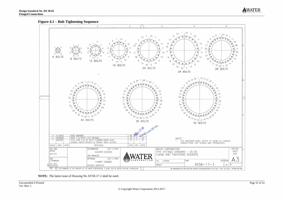
Design Standard No. DS 38-02
Flanged Connections
Uncontrolled if Printed Page 32 of 52 Ver 1Rev 1
© Copyright Water Corporation 2013-2017
Figure 4.1 – Bolt Tightening Sequence
NOTE: The latest issue of Drawing No AY58-17-1 shall be used.

Design Standard No. DS 38-02
Flanged Connections
Uncontrolled if Printed Page 33 of 52 Ver 1Rev 1
© Copyright Water Corporation 2013-2017
5 Appendix A - Bolting Torques (Informative) The following tables present the nominal required bolt torques for commonly used standard flange
sizes and pressure ratings. For bolting of proprietary items of equipment, refer to the Manufacturer’s
guidelines (limited information for proprietary equipment is provided in Sections 5.5 to 5.7).
5.1 Elastomeric Gasket Bolting Torques – Steel / DI Flanges
Table 5.1 – Elastomeric Gasket Bolting Torques for AS 4087 PN 16 Flanges
Bolt Size Bolt /torque (Nm)
Flat Face Flange Raised Face Flange
M16 120 26
M20 204 60
NOTES:
1. Assumed friction factor: µ = 0.12 based on Chemsearch Thread-Eze Ultra lubricant.
2. Elastomeric gasket material: EPDM rubber, thickness 3 mm, allowable gasket stress of 8 MPa @ 20 ºC
3. Grade 8.8 bolts for all flange sizes.
Table 5.2 – Elastomeric Gasket Bolting Torques for EN 1092 PN 16 Flanges
Bolt Size Bolt /torque – (Nm)
Flat Face Flange Raised Face Flange
M16 70 21
M20 134 38
M24 213 53
NOTES:
1. Assumed friction factor: µ = 0.12 based on Chemsearch Thread-Eze Ultra lubricant
2. Elastomeric gasket material: EPDM rubber, thickness 3 mm, allowable gasket stress of 8 MPa @ 20 ºC
3. Grade 8.8 bolts for all flange sizes.

Design Standard No. DS 38-02
Flanged Connections
Uncontrolled if Printed Page 34 of 52
Ver 1Rev 1
© Copyright Water Corporation 2013- 2017
5.2 Compressed Fibre (CF) Gasket Bolting Torques – Steel/DI Flanges
Table 5.3 – Galvanised Bolting Torques for AS 4087 PN16, 21, 35 and EN1092 PN25, 40 Flanges
Bolt Size Bolt /torque – (Nm)
M16 170
M20 331
M24 574
M27 833
M30 1137
M33 1528
M36 1971
M39 2538
M45 3917
NOTES:
1. Assumed friction factor: µ = 0.12 based on Chemsearch Thread-Eze Ultra lubricant
2. Raised face joint only.
3. Compressed fibre gasket material: Novus 30 or Klingersil C4430, thickness 3.0mm
4. Grade 8.8 bolts for all flange sizes
5. Bolt yield approximately 65%

Design Standard No. DS 38-02
Flanged Connections
Uncontrolled if Printed Page 35 of 52
Ver 1Rev 1
© Copyright Water Corporation 2013- 2017
Table 5.4 – Stainless Steel Bolting Torques for AS 4087 16, 21, 35 and EN1092 PN25, 40Flanges
Grade A4-70 Bolts
Bolt Size Bolt /torque – (Nm)
M16 129
M20 251
M24 435
M27 631
M30 861
Grade A4-80 Bolts
Bolt Size Bolt /torque – (Nm)
M33 1524
M36 1990
M39 2562
M45 3390
NOTES:
1. Assumed friction factor: µ = 0.12 based on Chemsearch Thread-Eze Ultra lubricant
2. Raised face joint only.
3. Compressed fibre gasket material: Novus 30 or Klingersil C4430, thickness 3.0mm.
4. Grade 8.8 bolts for all flange sizes
5. Bolt yield approximately 70%

Design Standard No. DS 38-02
Flanged Connections
Uncontrolled if Printed Page 36 of 52
Ver 1Rev 1
© Copyright Water Corporation 2013- 2017
5.3 Corporation-Designed Flanges Bolt Torques
Bolt torques, bolt and gasket specifications for Corporation designed flanges may be found on
drawings as referenced in the following table.
Table 5.5 – Corporation Designed Flanges
Flange Type Size (DN) Drg Number
PN 25 Raised face slip-on 900 – 1400 JZ39-91-4
PN 25 Flat face slip-on 700 – 1400 JZ39-91-5
PN 25 Raised face weld neck 1200 – 1400 JZ39-91-6
PN 25 Flat face weld neck 700 – 1400 JZ39-91-7
PN 40 Raised face weld neck 700 – 1400 JZ39-91-9

Design Standard No. DS 38-02
Flanged Connections
Uncontrolled if Printed Page 37 of 52
Ver 1Rev 1
© Copyright Water Corporation 2013- 2017
5.4 PE Flanged Joints Bolt Torques
The lack of standards and consistency between PE manufacturers with regards to the outside diameter
of stub flanges, the low stress tolerance of elastomeric gaskets and variation in diameters of what the
PE stub flange is mated to, makes specification of universal bolt torques difficult. The tabulated
torque figures presented in this section may be used subject to the indicated constraints. Inherently,
these torques are compromise values which allow coverage of a range of flange details. For this
reason, it is recommended that optimised bolt torques are determined for individual joints in
consultation with the PE or gasket manufacturer, alternatively suitable bolt torques may be determined
in accordance with the procedure outlined in Section 5.4.3.
All torques presented in this Section are based on the following common assumptions –
1. Assumed coefficient of friction: µ = 0.12 (friction factor 0.16) based on using Chemsearch
Thread-Eze Ultra lubricant
2. Flat or raised face mating flange against PE stub flange creating raised face joint.
3. Elastomeric gasket material: EPDM rubber, thickness 3 mm
a. target stress of 8 MPa @ 20 ºC with joint unpressurised
b. effective seal stress range of 2 MPa to 10 MPa
c. minimum gasket stress for pressurised joint 2.7 MPa
d. Allowance of +/-25% for torque wrench method inaccuracy
e. Mating flanges and backing rings are drilled in accordance with the applicable pressure
rating of AS4087. Flanges to a different standard but drilled to AS4087 should be
checked in accordance with procedure outlined in Section 5.4.3.
4. Grade 8.8 bolts for all flange sizes
In general, compressed fibre gaskets should not be used for joints where either flange is polyethylene,
this is because the gasket stresses required to form an effective seal will likely require bolt loads which
may deform the PE stub and backing ring, thereby reducing the effectiveness of the joint. If insulated
flange joints are required for dissimilar bolting / backing flange /mating flange materials, then
elastomeric gaskets shall be used with properties in accordance with this section and Section 2.11.1.
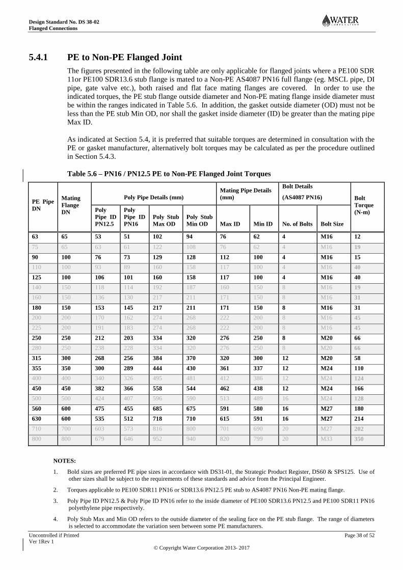
Design Standard No. DS 38-02
Flanged Connections
Uncontrolled if Printed Page 38 of 52
Ver 1Rev 1
© Copyright Water Corporation 2013- 2017
5.4.1 PE to Non-PE Flanged Joint
The figures presented in the following table are only applicable for flanged joints where a PE100 SDR
11or PE100 SDR13.6 stub flange is mated to a Non-PE AS4087 PN16 full flange (eg. MSCL pipe, DI
pipe, gate valve etc.), both raised and flat face mating flanges are covered. In order to use the
indicated torques, the PE stub flange outside diameter and Non-PE mating flange inside diameter must
be within the ranges indicated in Table 5.6. In addition, the gasket outside diameter (OD) must not be
less than the PE stub Min OD, nor shall the gasket inside diameter (ID) be greater than the mating pipe
Max ID.
As indicated at Section 5.4, it is preferred that suitable torques are determined in consultation with the
PE or gasket manufacturer, alternatively bolt torques may be calculated as per the procedure outlined
in Section 5.4.3.
Table 5.6 – PN16 / PN12.5 PE to Non-PE Flanged Joint Torques
PE Pipe
DN
Mating
Flange
DN
Poly Pipe Details (mm)
Mating Pipe Details
(mm)
Bolt Details
(AS4087 PN16) Bolt
Torque
(N-m) Poly
Pipe ID
PN12.5
Poly
Pipe ID
PN16
Poly Stub
Max OD
Poly Stub
Min OD Max ID Min ID No. of Bolts Bolt Size
63 65 53 51 102 94 76 62 4 M16 12
75 65 63 61 122 108 76 62 4 M16 19
90 100 76 73 129 128 112 100 4 M16 15
110 100 93 89 160 158 117 100 4 M16 40
125 100 106 101 160 158 117 100 4 M16 40
140 150 118 114 192 187 160 150 8 M16 19
160 150 136 130 217 211 171 150 8 M16 31
180 150 153 145 217 211 171 150 8 M16 31
200 200 170 162 274 268 222 200 8 M16 45
225 200 191 183 274 268 222 200 8 M16 45
250 250 212 203 334 320 276 250 8 M20 66
280 250 238 228 334 320 276 250 8 M20 66
315 300 268 256 384 370 320 300 12 M20 58
355 350 300 289 444 430 361 337 12 M24 110
400 400 340 326 495 481 412 386 12 M24 124
450 450 382 366 558 544 462 438 12 M24 166
500 500 424 407 596 590 513 489 16 M24 128
560 600 475 455 685 675 591 580 16 M27 180
630 600 535 512 718 710 615 591 16 M27 214
710 700 603 573 816 800 701 690 20 M27 202
800 800 679 646 952 940 820 799 20 M33 350
NOTES:
1. Bold sizes are preferred PE pipe sizes in accordance with DS31-01, the Strategic Product Register, DS60 & SPS125. Use of
other sizes shall be subject to the requirements of these standards and advice from the Principal Engineer.
2. Torques applicable to PE100 SDR11 PN16 or SDR13.6 PN12.5 PE stub to AS4087 PN16 Non-PE mating flange.
3. Poly Pipe ID PN12.5 & Poly Pipe ID PN16 refer to the inside diameter of PE100 SDR13.6 PN12.5 and PE100 SDR11 PN16
polyethylene pipe respectively.
4. Poly Stub Max and Min OD refers to the outside diameter of the sealing face on the PE stub flange. The range of diameters
is selected to accommodate the variation seen between some PE manufacturers.

Design Standard No. DS 38-02
Flanged Connections
Uncontrolled if Printed Page 39 of 52
Ver 1Rev 1
© Copyright Water Corporation 2013- 2017
5. Mating pipe details (Max & Min ID) refers to the inside diameter of the sealing face for the Non-PE mating flange. The
variation results from the consideration of mating with various types of pipe and components (eg. MSCL pipe, DI pipe, gate
valves etc.)
6. Pressure rating of the resulting joint shall be that of the lowest rated component, it is assumed that test pressure will not
exceed this rating.
7. DN combinations presented are based on best ID compatibility and available clearance between the OD of the stub and the
diameter to the inside surface of the bolts.
8. Overall dimensional compatibility of backing ring, stub flange and mating flanges for the size combination is the
responsibility of the designer.
9. Selection and procurement of components should ensure that the contact area between the back face of the stub and backing
ring is maximised. Backing rings used shall be suitable for the pressure rating of the joint.
10. The above figures may be suitable for mating with butterfly valves, however stub flange face dimensions and pipe ID shall be
checked to ensure compatibility with the butterfly valve (refer Section 2.6 for additional information regarding seal on body
valves). A PE butterfly valve spacer may be required to ensure that the butterfly valve disk does not fowl on the pipe ID.

Design Standard No. DS 38-02
Flanged Connections
Uncontrolled if Printed Page 40 of 52
Ver 1Rev 1
© Copyright Water Corporation 2013- 2017
5.4.2 PE to PE Flanged Joint
The figures presented in the following table are only applicable for flanged joints between PE100
SDR11 PN16 to like PE or PE100 SDR13.6 PN12.5 to like PE (ie. not intended for PN16 to PN12.5),
with backing ring drilled to AS4087 PN16. In order to use the indicated torques, the PE stub flange
outside diameter must be within the range indicated in Table 5.7. In addition, the gasket OD must not
be less than the PE stub Min OD, nor the gasket ID greater than the PN12.5 Poly Pipe ID.
Table 5.7 – PN16 / PN12.5 PE to PE Flanged Joint Torques
PE Pipe
DN
AS4087
Backing
Ring DN
Poly Pipe Details (mm)
Bolt Details
AS4087 PN16 Bolt
Torque
(N-m) Poly Pipe ID
PN12.5
Poly Pipe ID
PN16 Poly Stub
Max OD
Poly Stub
Min OD
No. of
Bolts Bolt Size
63 65 53 51 102 94 4 M16 24
75 65 63 61 122 108 4 M16 31
90 100 76 73 130 128 4 M16 43
110 100 93 89 160 158 4 M16 66
125 100 106 101 160 158 4 M16 55
140 150 118 114 193 187 8 M16 42
160 150 136 130 217 211 8 M16 52
180 150 153 145 217 211 8 M16 42
200 200 170 162 274 268 8 M16 86
225 200 191 183 274 268 8 M16 71
250 250 212 203 334 320 8 M20 144
280 250 238 228 334 320 8 M20 115
315 300 268 256 384 370 12 M20 109
355 350 300 289 444 430 12 M24 191
400 400 340 326 495 481 12 M24 233
450 450 382 366 558 544 12 M24 302
500 500 424 407 596 584 16 M24 243
560 600 475 455 669 657 16 M27 350
630 600 535 512 726 710 16 M27 370
710 700 603 573 816 800 20 M27 375
800 800 679 646 952 940 20 M33 701
NOTES:
1. Bold sizes are preferred PE pipe sizes in accordance with DS31-01, the Strategic Product Register, DS60 & SPS125. Use of
other sizes shall be subject to the requirements of these standards and advice from the Principal Engineer.
2. Poly Pipe ID PN12.5 & Poly Pipe ID PN16 refer to the inside diameter of PE100 SDR13.6 PN12.5 and PE100 SDR11 PN16
polyethylene pipe respectively.
3. Poly Stub Max and Min OD refers to the outside diameter of the sealing face on the PE stub flange. The range of diameters
is selected to accommodate the variation seen between some PE manufacturers.
4. DN combinations presented are based on best ID compatibility and available clearance between the OD of the stub and the
diameter to the inside surface of the bolts.
5. Overall dimensional compatibility of backing ring, stub flange and mating flanges for the size combination is the
responsibility of the designer.
6. Selection and procurement of components should ensure that the contract area between the back face of the stub and backing
ring maximize the contact area. Backing rings used shall be suitable for the pressure rating of the joint.
7. It is assumed that test pressure will not exceed the flange rating.
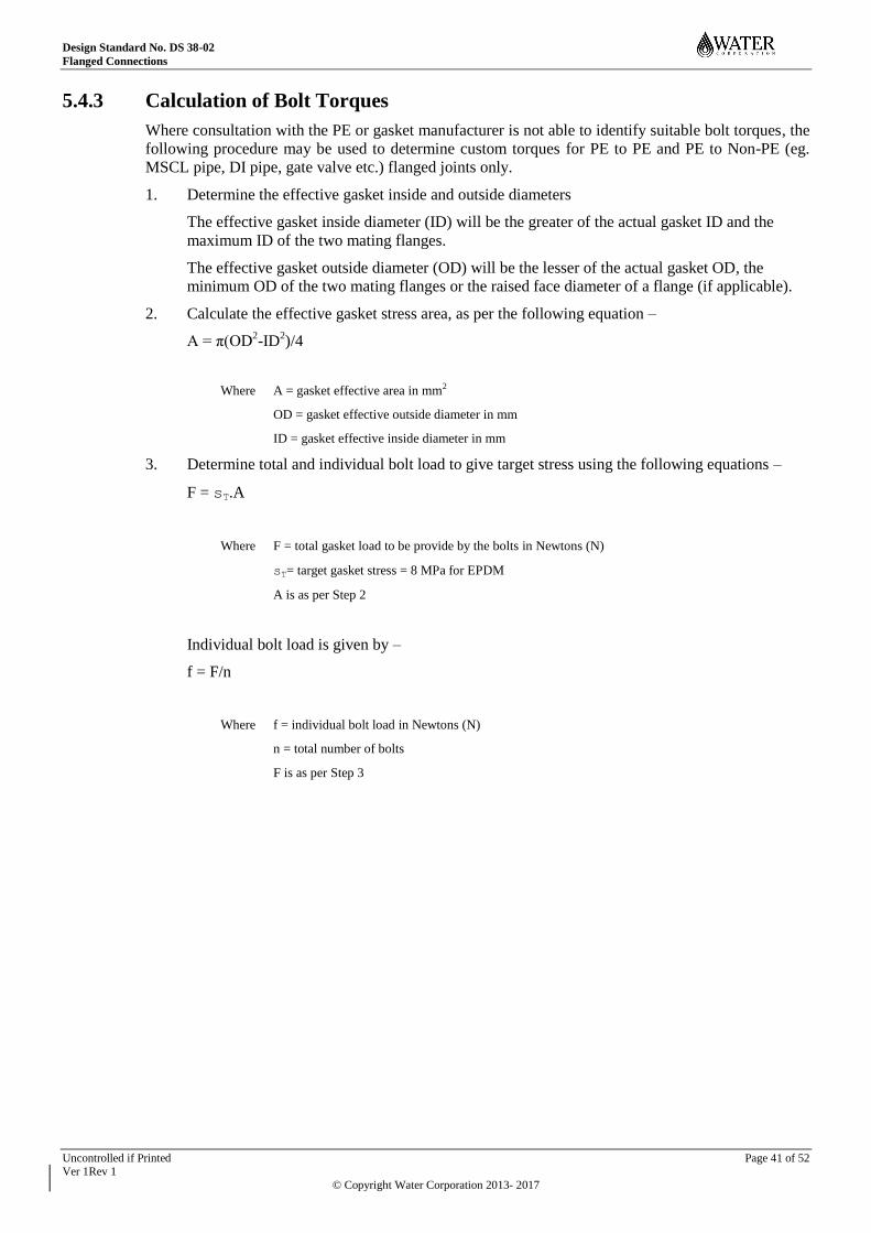
Design Standard No. DS 38-02
Flanged Connections
Uncontrolled if Printed Page 41 of 52
Ver 1Rev 1
© Copyright Water Corporation 2013- 2017
5.4.3 Calculation of Bolt Torques
Where consultation with the PE or gasket manufacturer is not able to identify suitable bolt torques, the
following procedure may be used to determine custom torques for PE to PE and PE to Non-PE (eg.
MSCL pipe, DI pipe, gate valve etc.) flanged joints only.
1. Determine the effective gasket inside and outside diameters
The effective gasket inside diameter (ID) will be the greater of the actual gasket ID and the
maximum ID of the two mating flanges.
The effective gasket outside diameter (OD) will be the lesser of the actual gasket OD, the
minimum OD of the two mating flanges or the raised face diameter of a flange (if applicable).
2. Calculate the effective gasket stress area, as per the following equation –
A = π(OD2-ID
2)/4
Where A = gasket effective area in mm2
OD = gasket effective outside diameter in mm
ID = gasket effective inside diameter in mm
3. Determine total and individual bolt load to give target stress using the following equations –
F = sT.A
Where F = total gasket load to be provide by the bolts in Newtons (N)
sT= target gasket stress = 8 MPa for EPDM
A is as per Step 2
Individual bolt load is given by –
f = F/n
Where f = individual bolt load in Newtons (N)
n = total number of bolts
F is as per Step 3

Design Standard No. DS 38-02
Flanged Connections
Uncontrolled if Printed Page 42 of 52
Ver 1Rev 1
© Copyright Water Corporation 2013- 2017
4. Calculate bolt torque –
Bolt torques are calculated in accordance with the simplified equation as per Section 6.6 of ESA
/ FSA Publication No 009/98 Guidelines for safe seal usage – Flanges and Gaskets (Part 1 –
guidelines for maintenance operators / engineers / fitters).
T = (f/1000) x 0.16 x db
Where T = torque per fastener in N.m
f is as per Step 3
db = nominal diameter of fastener in mm (ie. db = 16 for M16 bolt etc.)
0.16 = factor loss due to friction (equivalent to coefficient of friction: µ = 0.12)
The resulting bolt torque when applied to each bolt in accordance with the procedures outlined
in Section 4.6.2, subject to the accuracy of torque wrench method, should produce a gasket
stress near the target stress of 8 MPa in the unpressurised condition. The gasket stress should be
back calculated for a pressurised joint to ensure that the stress remains within the acceptable
range (nominally 2.7 to 8 MPa), refer following Step 5.
The calculated bolt torque should also be checked as per Step 6 to confirm that bolts will not be
overstressed.
5. Gasket Stress Check
Calculate hydrostatic end force is the resulting axial force on the joint by virtue of the internal
pressure, it may be calculated using the following equation –
FH = π.ID2/4 x P
Where FH = hydrostatic end force in N
ID is as per Step 2 above.
P = Rated Pressure in MPa (ie. PN16 = 1.6 MPa)
With the joint pressurised, the resulting effective compressive load on the gasket will be the
total bolt pre-load minus the hydrostatic end force (ie. F - FH) and so the resulting gasket stress
in the pressurised condition may be calculated using the following equation –
sP = (F – FH) / A
Where sP = gasket stress with the flanged joint pressurised in MPa
F is as per Step 3
FH is as above
A is as per Step 2
If the stress calculated with the joint pressurised is between 2.7 MPa and 8 MPa, the bolt
torques calculated at Step 4 are suitable for the application. If the stress is not within this range
then the gasket manufacturer should be contacted for advice.
6. Bolt Stress Check
It is highly unlikely that an unacceptable bolt stress would be achieved when using grade 8.8
bolts, however to ensure this, the adequacy of the bolts should be checked as follows. The
below table lists torques which will give a bolt stress of approximately 65% of grade 8.8 bolt

Design Standard No. DS 38-02
Flanged Connections
Uncontrolled if Printed Page 43 of 52
Ver 1Rev 1
© Copyright Water Corporation 2013- 2017
yield. If the bolt torque T calculated at Step 4 is less than the torque listed in the following table
for the given bolt size, then the bolt torque T from Step 4 is suitable for the use of grade 8.8
bolts.
Table 5.8 – Bolt Torque at ~65% Grade 8.8 Bolt Yield
If torque T from Step 4 is greater than the listed value, then the calculated tor que is not
suitable and the PE / gasket manufacturer should be consulted for suitable bolting / torques.
Bolt Size Torque
Nm
M16 170
M20 331
M24 574
M27 833
M33 1137

Design Standard No. DS 38-02
Flanged Connections
Uncontrolled if Printed Page 44 of 52
Ver 1Rev 1
© Copyright Water Corporation 2013- 2017
5.5 Magnetic Flow Meter Bolt Torques
The information presented in this section is for makes / models as per the Water Corporation SCADA
Approved Equipment List. Where a different magnetic flow meter is used, the manufacturer shall be
consulted to determine suitable bolt torques and assembly details.
5.5.1 Siemens
The torque figures presented in the following table are taken directly from the Siemens Quick Start
publication (edition 09/2009-revision 6) for the Siemens MAG 3100 / 3100HT / 3100P / 5100W. The
5100W is commonly used on Water Corporation jobs and hence the torques will be applicable in many
cases.
Table 5.9 – Siemens MFM Bolt Torques
DN
Bolt Torque N-m
AS4087
PN16
AS4087
PN21
AS4087
PN35
50 21 33 33
65 22 22 22
80 32 28 28
100 50 35 35
150 60 50 50
200 55 78 37
250 94 110 49
300 72 105 43
350 153 164 94
400 172 158 105
450 224 204 129
500 198 210 141
600 287 277 183
700 228 246 207
800 426 304 286
900 416 371 287
1000 386 326 326
1200 443 471 471
NOTES:
1. Use Chemsearch Thread-Eze Ultra lubricant
2. Gasket material not exceeding 75 shore A durometer (refer Section 2.11)
3. Grade 8.8 bolts for all flange sizes.
4. Do not use compressed fibre gasket unless under direct advice of the manufacturer.
5. The information presented in this table is interim. It is expected that Siemens will revise their requirements to indicate
that higher torques are suitable. At that time the above recommended torques will be revised.

Design Standard No. DS 38-02
Flanged Connections
Uncontrolled if Printed Page 45 of 52
Ver 1Rev 1
© Copyright Water Corporation 2013- 2017
5.5.2 Endress & Hauser
The Promag 400 is also approved for use in Water Corporation installations. The torque values below
are taken directly from their Proline Promag W 400 Operating Instructions (version 02.00.zz). E&H
do not as standard list torques for PN21 or PN35 meters, they advise that these will be provided as
needed.
Table 5.10 – E&H MFM Bolt Torques
DN
Bolt Torque N-m
AS4087
PN16
AS4087
PN21
AS4087
PN35
50 32 - -
80 49 - -
100 76 - -
150 52 - -
200 77 - -
250 147 - -
300 103 - -
350 203 - -
375 137
400 226 - -
450 301 - -
500 271 - -
600 393 - -
700 330 - -
800 631 - -
900 627 - -
1000 595 - -
1200 703 - -
NOTES:
1. Use Chemsearch Thread-Eze Ultra lubricant
2. Gasket material refer Section 2.11
3. Grade 8.8 bolts for all flange sizes.
4. Do not use compressed fibre gasket unless under direct advice of the manufacturer.

Design Standard No. DS 38-02
Flanged Connections
Uncontrolled if Printed Page 46 of 52
Ver 1Rev 1
© Copyright Water Corporation 2013- 2017
5.6 Butterfly Valve Bolt Torques
The torques presented are for mating against Steel or DI flanges with Grade 8.8 bolting, the bolts
should be lubricated in accordance with Section 4.5. The manufacturer should be consulted for mating
against flanges of other materials or bolting in other grades. In general tightening procedure as per
Section 4.6.2 & Section 4.6.3 should be followed.
5.6.1 SPS261 Seal on Body Butterfly Valves
Flanged joints for seal on body valves are covered in Section 2.6. A gasket is not required, the seal is
made against the body liner which wraps around onto the valve face.
5.6.1.1 EBRO F012A
The tightening torques presented in the following table are maximum values appropriate for AS4087
PN16 & PN21, also EN1092 PN25 drilled flanges.
Table 5.11 – Bolt Torques EBRO F012ABolt Size Bolt Torque – (Nm)
M10 30
M12 50
M16 115
M20 230
M24 530
M27 780
M30 1070
M33 1440
M36 1865
M39 2415
M42 4400
M45 5500
M48 6640
M52 8500
M56 10495
NOTES:
1. Use Chemsearch Thread-Eze Ultra lubricant
2. Grade 8.8 bolts for all flange sizes.
3. No gasket is required, seal is achieved by compressing the elastomeric body liner.
4. The tabulated values provided by EBRO are based on a percentage of bolt yield which will not damage the bolts or
flanges, but will ensure metal to metal contact on the flange faces to create an effective seal. Crush on the valve
elastomeric liner is limited by this arrangement.

Design Standard No. DS 38-02
Flanged Connections
Uncontrolled if Printed Page 47 of 52
Ver 1Rev 1
© Copyright Water Corporation 2013- 2017
5.6.1.2 Wouter Witzel Series 75 (EVFS)
Wouter Witzel recommend that the bolts are tightened in a criss-cross fashion until there is metal on
metal contact between the raised face on the butterfly valve and the mating flange (refer to below
diagram).
NOTES:
1. Use Chemsearch Thread-Eze Ultra lubricant
2. Grade 8.8 bolts for all flange sizes.
3. No gasket is required, seal is achieved by compressing the elastomeric body liner.
5.6.1.3 Keystone Resilient Seated Butterfly Valves
The tightening torques presented in the following table are maximum values appropriate for AS4087
PN16 & PN21 drilled flanges using galvanized bolting.
Table 5.12 – Bolt Torques Keyston Resilient Seated Butterfly Valves
Bolt Size Bolt Torque – (Nm)
M12 25
M16 60
M20 82
M24 204
M27 285
M30 413
M33 526
M36 707
1. Use Chemsearch Thread-Eze Ultra lubricant
2. Grade 8.8 bolts for all flange sizes.
3. No gasket is required, seal is achieved by compressing the elastomeric body liner.
4. The tabulated values provided are based on torques provided by Emerson for AS2129 flanges, multiplied by 1.4 for
zinc plating and 1.05 for max value.
5.6.2 SPS262 Seal on Disk Butterfly Valves
Narrow face joint as per Section 2.7.2 will be typical for these valves.
5.6.2.1 OZ-KAN W25
Refer to Section 5.2 for suitable torques.
5.6.2.2 VAG EKN
Refer to Section 5.2 for suitable torques.

Design Standard No. DS 38-02
Flanged Connections
Uncontrolled if Printed Page 48 of 52
Ver 1Rev 1
© Copyright Water Corporation 2013- 2017
5.7 Existing Vintage Grey Cast Iron Valves
In the limited circumstances where existing aged valves are to be re-used, reference may be made to
Section 1.7.1 of DS38-03 Ver 1 Rev 0 for suitable torques. A copy of the relevant page may be found
at Aqua #17309429.

Design Standard No. DS 38-02
Flanged Connections
Uncontrolled if Printed Page 49 of 52
Ver 1Rev 1
© Copyright Water Corporation 2013- 2017
6 Appendix B – Flange / Gasket Sizing (Informative) The following tables present the nominal required flange and gasket sizing information for commonly
used standard flange sizes and pressure ratings.
Table 6.1 – AS 4087 PN 16 Flanges
Flange Size Gasket ID
(mm)
Flange OD
(mm)
PCD (mm) No of Bolts Size of Bolts
80 82 185 146 4 M16
100 100 215 178 4 M16
150 154 280 235 8 M16
200 250 335 292 8 M16
250 259 405 356 8 M20
300 310 455 406 12 M20
400 392 580 521 12 M24
500 494 705 641 16 M24
600 594 825 756 16 M27
700 695 910 845 20 M27
800 795 1060 984 20 M33
900 896 1175 1092 24 M33
1000 996 1255 1175 24 M33
1200 1197 1490 1410 32 M33
Table 6.2 –EN 1092 PN 16 Flanges
Flange Size Gasket ID
(mm)
Flange OD
(mm)
PCD (mm) No of Bolts Size of Bolts
80 82 200 160 8 M16
100 100 220 180 8 M16
150 154 285 240 8 M20
200 250 340 295 12 M20
250 259 405 355 12 M24
300 310 460 410 12 M24
400 392 580 525 16 M27
500 494 715 650 20 M30
600 594 840 770 20 M33
700 695 910 840 24 M33
800 795 1025 950 24 M36
900 896 1125 1050 28 M36
1000 996 1255 1170 28 M39
1200 1197 1485 1390 32 M45

Design Standard No. DS 38-02
Flanged Connections
Uncontrolled if Printed Page 50 of 52
Ver 1Rev 1
© Copyright Water Corporation 2013- 2017
Table 6.3 –AS 4087 PN21/PN35 Flanges
Flange Size Gasket ID
(mm)
Flange OD
(mm)
PCD (mm) No of Bolts Size of Bolts
80 82 205 165 8 M16
100 100 230 191 8 M16
150 154 305 260 12 M20
200 250 370 324 12 M20
250 259 430 381 12 M24
300 310 490 438 16 M24
400 392 610 552 20 M27
500 594 735 673 24 M30
600 695 850 781 24 M33
700 795 935 857 24 M33
800 896 1060 984 28 M33
900 908 1185 1105 32 M36
1000 996 1275 1194 36 M36
1200 1197 1530 1441 40 M39
Table 6.4 –EN 1092 PN 25 Flanges
Flange Size Gasket ID
(mm)
Flange OD
(mm)
PCD (mm) No of Bolts Size of Bolts
80 82 200 160 8 M16
100 100 235 190 8 M20
150 154 300 250 8 M24
200 250 360 310 12 M24
250 259 425 370 12 M27
300 310 485 430 16 M27
400 392 620 550 16 M33
500 494 730 660 20 M33
600 594 845 770 20 M36

Design Standard No. DS 38-02
Flanged Connections
Uncontrolled if Printed Page 51 of 52
Ver 1Rev 1
© Copyright Water Corporation 2013- 2017
Table 6.5 –EN 1092, PN 40 Flanges
Flange Size Gasket ID
(mm)
Flange OD
(mm)
PCD (mm) No of Bolts Size of Bolts
80 82 200 160 8 M16
100 100 235 190 8 M20
150 154 300 250 8 M24
200 250 375 320 12 M27
250 259 450 385 12 M30
300 310 515 450 16 M30
400 392 660 585 16 M36
500 494 755 670 20 M39
600 594 890 795 20 M45
Design Standard No. DS 38-02
Flanged Connections
Uncontrolled if Printed Page 52 of 52
Ver 1Rev 1
© Copyright Water Corporation 2013- 2017
End of Document
![Electrical Design Standard Symbols - BN-DS-E2_02 [PDF Library]](https://static.fdocuments.us/doc/165x107/54783c225906b55f318b47a5/electrical-design-standard-symbols-bn-ds-e202-pdf-library.jpg)