Design Rules for High Damping in Mobile Hydraulic Systems · The 13th Scandinavian International...
8
The 13th Scandinavian International Conference on FluidPower, SICFP2013, June 3-5, 2013, Linköping, Sweden Design Rules for High Damping in Mobile Hydraulic Systems Mikael Axin and Petter Krus Division of Fluid and Mechatronic Systems, Department of Management and Engineering, Linköping University, Sweden E-mail: [email protected], [email protected] Abstract This paper analyses the damping in pressure compensated closed centre mobile working hy- draulic systems. Both rotational and linear loads are covered and the analysis applies to any type of pump controller. Only the outlet orifice in the directional valve will provide damping to a pressure compensated system. Design rules are proposed for how the system should be dimensioned in order to obtain a high damping. The volumes on each side of the load have a high impact on the damping. In case of a small volume on the inlet side, the damping be- comes low. However, the most important thing is to design the outlet orifice area properly. There exists an optimal orifice dimension for maximized damping; both smaller and larger orifice areas give lower damping independently of the volumes. This paper presents a method to dimension the outlet orifice area and the load volumes in order to obtain a desired system damping. Experimental results, which confirm the theoretical expectations, are also presen- ted. The conclusions are that it is possible to obtain a high damping contribution from the outlet orifice if the system is dimensioned correctly. However, the energy efficiency needs to be considered while improving the damping. Keywords: Damping, compensator, outlet orifice, efficiency 1 Introduction In most fluid power systems, directional valves control the speed of the actuators. Two different types of valves are commonly used in mobile machines; open centre and closed centre. This paper addresses closed centre valves. Closed centre valves are commonly used in systems where the pump is actively controlled, for example in constant pressure and load sensing systems [1] [2] [3]. Several loads often share one common pump in mobile ma- chines. If the system pressure level is adapted to the highest load and several functions are operated simultaneously, load interference challenges will occur. This means that the pres- sure level at the highest load will affect the velocity of the lighter loads. In applications where velocity control is an im- portant property, the valves are often equipped with pressure compensators. The pressure drop across all directional valves will then be constant and the flow will be proportional to the opening area of the valve. A drawback with pressure compensators is that the load will be poorly damped [4]. To obtain damping from a valve, the flow has to increase when the pressure drop across the valve increases and vice versa. A pressure compensated valve en- deavours to achieve low influence on the flow from the load pressure. Except for secondary effects such as leakage, stiff- ness of the compensator spring and load friction, only the out- let orifice in the directional valve will provide damping to a pressure compensated actuator. A hydraulic system with poor damping has a tendency to oscillate, which has a negative im- pact on both the productivity of the application and the com- fort of the operator [5]. This paper analyses the damping in systems using pressure compensated closed centre valves. Both rotational and linear loads are covered. The pump controller can be of any type; it does not affect the analysis. Design rules for how the system should be dimensioned in order to obtain a high damping are proposed. Experimental results, which confirm the theoretical expectations, are also presented. 2 Damping A valve will with contribute damping if the flow increases when the pressure drop across the valve increases and vice versa. An example of a hydraulic system with high damping is the constant pressure system, see figure 1. The pump is controlled to maintain a constant pressure before the valve. If the load starts to oscillate, the pressure in the cylinder will also oscillate. Increased cylinder pressure, which means an accelerating force on the piston, results in decreased pressure drop across the valve and consequently also decreased flow through the valve. The acceleration will then be slowed down and the oscillations will decrease, as shown in figure 1. If the directional valve is complemented with a pressure com- pensator, a constant flow valve is realized. The function of the pressure compensator is to maintain a constant pressure drop across the directional valve, regardless of pressure variations 13
-
Upload
truonghanh -
Category
Documents
-
view
213 -
download
0
Transcript of Design Rules for High Damping in Mobile Hydraulic Systems · The 13th Scandinavian International...

The 13th Scandinavian International Conference on Fluid Power, SICFP2013, June 3-5, 2013, Linköping, Sweden
Design Rules for High Damping in Mobile Hydraulic Systems
Mikael Axin and Petter Krus
Division of Fluid and Mechatronic Systems, Department of Management and Engineering, Linköping University, Sweden
E-mail: [email protected], [email protected]
Abstract
This paper analyses the damping in pressure compensated closed centre mobile working hy-
draulic systems. Both rotational and linear loads are covered and the analysis applies to any
type of pump controller. Only the outlet orifice in the directional valve will provide damping
to a pressure compensated system. Design rules are proposed for how the system should be
dimensioned in order to obtain a high damping. The volumes on each side of the load have
a high impact on the damping. In case of a small volume on the inlet side, the damping be-
comes low. However, the most important thing is to design the outlet orifice area properly.
There exists an optimal orifice dimension for maximized damping; both smaller and larger
orifice areas give lower damping independently of the volumes. This paper presents a method
to dimension the outlet orifice area and the load volumes in order to obtain a desired system
damping. Experimental results, which confirm the theoretical expectations, are also presen-
ted. The conclusions are that it is possible to obtain a high damping contribution from the
outlet orifice if the system is dimensioned correctly. However, the energy efficiency needs to
be considered while improving the damping.
Keywords: Damping, compensator, outlet orifice, efficiency
1 Introduction
In most fluid power systems, directional valves control the
speed of the actuators. Two different types of valves are
commonly used in mobile machines; open centre and closed
centre. This paper addresses closed centre valves. Closed
centre valves are commonly used in systems where the pump
is actively controlled, for example in constant pressure and
load sensing systems [1] [2] [3].
Several loads often share one common pump in mobile ma-
chines. If the system pressure level is adapted to the highest
load and several functions are operated simultaneously, load
interference challenges will occur. This means that the pres-
sure level at the highest load will affect the velocity of the
lighter loads. In applications where velocity control is an im-
portant property, the valves are often equipped with pressure
compensators. The pressure drop across all directional valves
will then be constant and the flow will be proportional to the
opening area of the valve.
A drawback with pressure compensators is that the load will
be poorly damped [4]. To obtain damping from a valve, the
flow has to increase when the pressure drop across the valve
increases and vice versa. A pressure compensated valve en-
deavours to achieve low influence on the flow from the load
pressure. Except for secondary effects such as leakage, stiff-
ness of the compensator spring and load friction, only the out-
let orifice in the directional valve will provide damping to a
pressure compensated actuator. A hydraulic system with poor
damping has a tendency to oscillate, which has a negative im-
pact on both the productivity of the application and the com-
fort of the operator [5].
This paper analyses the damping in systems using pressure
compensated closed centre valves. Both rotational and linear
loads are covered. The pump controller can be of any type; it
does not affect the analysis. Design rules for how the system
should be dimensioned in order to obtain a high damping are
proposed. Experimental results, which confirm the theoretical
expectations, are also presented.
2 Damping
A valve will with contribute damping if the flow increases
when the pressure drop across the valve increases and vice
versa. An example of a hydraulic system with high damping
is the constant pressure system, see figure 1. The pump is
controlled to maintain a constant pressure before the valve.
If the load starts to oscillate, the pressure in the cylinder will
also oscillate. Increased cylinder pressure, which means an
accelerating force on the piston, results in decreased pressure
drop across the valve and consequently also decreased flow
through the valve. The acceleration will then be slowed down
and the oscillations will decrease, as shown in figure 1.
If the directional valve is complemented with a pressure com-
pensator, a constant flow valve is realized. The function of the
pressure compensator is to maintain a constant pressure drop
across the directional valve, regardless of pressure variations
13
Vel
oci
ty[-
]
Time [-]
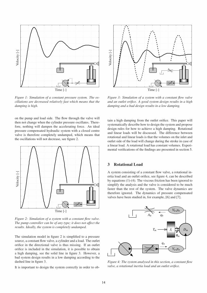
Figure 1: Simulation of a constant pressure system. The os-
cillations are decreased relatively fast which means that the
damping is high.
on the pump and load side. The flow through the valve will
then not change when the cylinder pressure oscillates. There-
fore, nothing will dampen the accelerating force. An ideal
pressure compensated hydraulic system with a closed centre
valve is therefore completely undamped, which means that
the oscillations will not decrease, see figure 2.
Vel
oci
ty[-
]
Time [-]
Figure 2: Simulation of a system with a constant flow valve.
The pump controller can be of any type; it does not affect the
results. Ideally, the system is completely undamped.
The simulation model in figure 2 is simplified to a pressure
source, a constant flow valve, a cylinder and a load. The outlet
orifice in the directional valve is thus missing. If an outlet
orifice is included in the simulation, it is possible to obtain
a high damping, see the solid line in figure 3. However, a
bad system design results in a low damping according to the
dashed line in figure 3.
It is important to design the system correctly in order to ob-
Vel
oci
ty[-
]
Time [-]
Figure 3: Simulation of a system with a constant flow valve
and an outlet orifice. A good system design results in a high
damping and a bad design results in a low damping.
tain a high damping from the outlet orifice. This paper will
systematically describe how to design the system and propose
design rules for how to achieve a high damping. Rotational
and linear loads will be discussed. The difference between
rotational and linear loads is that the volumes on the inlet and
outlet side of the load will change during the stroke in case of
a linear load. A rotational load has constant volumes. Experi-
mental verifications of the findings are presented in section 5.
3 Rotational Load
A system consisting of a constant flow valve, a rotational in-
ertia load and an outlet orifice, see figure 4, can be described
by equations (1)-(4). The viscous friction has been ignored to
simplify the analysis and the valve is considered to be much
faster than the rest of the system. The valve dynamics are
therefore ignored. The dynamics of pressure compensated
valves have been studied in, for example, [6] and [7].
qa
qbAb
Va,pa
Vb,pb
Dm
θm
JtTm
Figure 4: The system analysed in this section, a constant flow
valve, a rotational inertia load and an outlet orifice.
14

qa −Dm
dθm
dt=
Va
βe
d pa
dt(1)
Jt
d2θm
dt2= Dm(pa − pb)−Tm (2)
Dm
dθm
dt−qb =
Vb
βe
d pb
dt(3)
qb = qa =CqAb
√
2
ρpb (4)
Linearized and Laplace transforming equations (1)-(4) result
in equations (5)-(8). The derivation of the equations is shown
in [8].
Qa −Dmsθm =Va
βe
sPa (5)
Jts2θm = Dm(Pa −Pb)−Tm (6)
Dmsθm −Qb =Vb
βe
sPb (7)
Qb = KcbPb (8)
where
Kcb=
∂qb
∂ pb
=CqAb√
2ρ pb
(9)
An expression for Kcbwhere maximum damping is obtained
has been derived in [9] for a linear load. Substituting to a
rotational load gives the expression in equation (10).
Kcbopt= Dm
√
Vb
βeJt (γ −1)γ3/4 (10)
where
γ = 1+Va
Vb
(11)
The maximum damping of the system can be calculated using
equation (12), also derived in [9].
δhmax=
1
2(√
γ −1) (12)
The most common system design is that the volumes on each
side of the load are equal. In that case, the maximum damp-
ing of the system is δh = 0.21 according to equations (11)
and (12). To obtain the optimal damping, the required outlet
orifice area can be calculated using equations (4), (9) and (10),
resulting in equation (13).
Abopt=
√
qaKcboptρ
C2q
(13)
The outlet orifice opening area should according to equa-
tion (13) increase with the square root of the inlet flow rate;
all other parameters are constant. Since the valve is assumed
to be pressure compensated, the inlet flow is directly propor-
tional to the inlet orifice opening area. The damping as a func-
tion of the outlet orifice area is shown in figure 5.
0
0.1
0.2
0.3
0.4
0.5
0.6
0.7
0.8
Dam
pin
g[-
]
Increased opening area-
Figure 5: The damping as a function of the opening area for
the outlet orifice. The volumes on each side of the load are
assumed to be equal.
It is possible to obtain a higher damping than δh = 0.21 by
changing the volumes on each side of the piston. To increase
the damping, the volume on the inlet side should be large
compare to the volume on the outlet side according to equa-
tions (11) and (12). As can be seen in figure 6, it is possible
to obtain a high damping contribution from the outlet orifice
by increasing the volume on the inlet side. For example, the
maximum damping becomes δh = 0.72 if the inlet volume is
five times larger than the outlet volume.
0
0.1
0.2
0.3
0.4
0.5
0.6
0.7
0.8
Dam
pin
g[-
]
Increased opening area
inlet volume increasinginlet volume increasinginlet volume increasing
-
Figure 6: A higher damping can be obtained if the inlet
volume is large compared to the outlet volume.
Increasing the inlet volume will increase the damping. How-
ever, there are drawbacks with this approach. In case of chan-
ging the flow direction, and thereby the direction of the ro-
tation, there will be a large volume at the outlet side instead.
Consequently, the damping will be low, see figure 7. If the
outlet volume is five times larger than the inlet volume, the
maximum damping is δh = 0.05.
15

0
0.1
0.2
0.3
0.4
0.5
0.6
0.7
0.8
Dam
pin
g[-
]
Increased opening area
inlet volume decreasinginlet volume decreasinginlet volume decreasing
-
Figure 7: The damping will be low if the inlet volume is small
compared to the outlet volume. This will be the case if the
flow direction changes compared to figure 6.
To dimension the outlet orifice area in order to get a desired
damping, the load needs to be known, see equation (10).
In mobile hydraulic applications, the load situation varies
greatly over time in a typical working cycle. It is therefore im-
portant to consider the load when designing the outlet orifice
area. It is only possible to optimize the damping for a specific
load. The damping will no longer be optimal if the load situ-
ation alters. In figure 8, it is shown how a load change will in-
fluence the damping. It is assumed that the outlet orifice area
is dimensioned to obtain the highest possible damping for a
nominal load. It is then shown how an increased/decreased
load will affect the damping.
0
0.1
0.2
0.3
0.4
0.5
0.6
0.7
0.8
Dam
pin
g[-
]
Increased opening area
Jt decreased 10 times
Jt increased 10 times
-
Figure 8: The outlet orifice area is designed to obtain the
optimal damping for a nominal load. It is then shown how
the damping will change if the load situation alters.
As can be seen in figure 8, the damping will decrease if the
load changes. From an efficiency point of view, it is advant-
ageous to have as large opening area of the outlet orifice as
possible. The pressure drop across the valve can then be kept
small, resulting in low losses. It is therefore recommended to
design the opening area to be optimal for the minimum load.
By doing so, the damping will be optimal for that load and
then decrease for higher loads. Designing the opening area
optimally for the minimum load maximizes the optimal out-
let orifice area according to equations (10) and (13).
4 Linear Load
A system consisting of a constant flow valve, a linear load
with a gear ratio and an outlet orifice, see figure 9, can be de-
scribed by similar equations as the rotational load in section 3.
Equations (14)-(17) describe the linearized system. The vis-
cous friction in the cylinder has been ignored to simplify the
analysis.
pa
qa
Ac
Va
Vb
κ
qb
pb
mL
U
Ab
xp
Figure 9: The system analysed in this section, a constant flow
valve, a linear load with a gear ratio and an outlet orifice.
Qa −AcsXp =Va
βe
sPa (14)
U2mLs2Xp = AcPa −κAcPb −Fp (15)
κAcsXp −Qb =Vb
βe
sPb (16)
Qb = KcbPb (17)
The expression for Kcbwhere maximum damping is obtained
is shown in equation (18) and the maximum damping is cal-
culated in the same ways as for a rotational load, see equa-
tion (12) [9].
Kcbopt= κAc
√
Vb
βeU2mL(γ −1)
γ3/4 (18)
where
γ = 1+κ2 Va
Vb
(19)
The outlet orifice area where optimal damping is obtained is
derived according to equation (20).
Abopt=
√
κqaKcboptρ
C2q
(20)
16

The difference between rotational and linear loads is that the
volumes on the inlet and outlet side of the load will change
during the stroke in case of a linear load. In the following
example, a dead volume of 20% is assumed on each side of
the piston. While the piston moves upwards, the inlet volume
will increase and the outlet volume decrease. The damping
will therefore increase during the stroke. In figure 10, the
damping as a function of the outlet orifice opening area is
shown during a whole stroke.
0
0.1
0.2
0.3
0.4
0.5
0.6
0.7
0.8
Dam
pin
g[-
]
Increased opening area
piston moves upwardspiston moves upwardspiston moves upwardspiston moves upwardspiston moves upwards
-
Figure 10: The damping will increase during the cylinder
stroke. A dead volume of 20% on each side of the piston is
assumed.
One design approach is to maximize the damping in the worst
case scenario. In that case, the outlet orifice area should be di-
mensioned optimally at the piston’s lower end position. The
damping will then increase while the piston moves upwards,
see the solid line in figure 11. It is possible to design the outlet
orifice area smaller if a higher damping is required. However,
drawbacks with that approach are slightly lower damping at
the piston’s lower end position, see the dashed line in fig-
ure 11, and higher losses across the orifice. A large opening
area will reduce the losses at the outlet orifice. This, however,
is at the expense of a lower damping, see the dashed-dotted
line in figure 11. There is no point in designing the opening
area to the left of the peaks in figure 10, since the damping
will then be low while the losses are large. In applications
where damping is important, it is appropriate to design the
outlet orifice somewhere between the optimal area at the pis-
ton’s lower end position and the optimal area at the piston’s
higher end position.
It is possible to obtain a higher damping than δh = 0.05 at the
piston’s lower end position by increasing the dead volumes in
the cylinder. For example, in case of 50% dead volume, the
optimal damping would increase to δh = 0.11 at the lower end
position, see figure 12. Drawbacks with this approach are that
the system response will decrease and that more space will be
required. By increasing the dead volumes further, the volume
change can eventually be ignored and the damping becomes
constant, similar to the rotational load in figure 5.
0
0.05
0.1
0.15
0.2
0.25
0.3
0.35
0.4
Dam
pin
g[-
]
Piston moves upwards-
Figure 11: Three different designs of the outlet orifice area.
The solid line shows an orifice area where the damping is
optimized at the piston’s lower end position, the dashed line
shows a smaller orifice area and the dashed-dotted line a lar-
ger orifice area. The losses will increase with a decreased
orifice area.
Similar to the rotational load case, the load needs to be taken
into consideration when designing the outlet orifice, see equa-
tion (18). It is shown how a load change affects the damping
in figure 13. The damping is assumed to be optimized for a
nominal load when the piston is at its lower end position. It
is then shown how an increased/decreased load will affect the
damping.
For the linear load case, it is not obvious to design the opening
area to be optimal for the minimum load. This is because the
optimal opening area will change while the piston moves up-
wards. Designing the opening area to be optimal for the min-
imum load will minimize the losses since the opening area can
be designed large, see equations (18) and (20). However, the
damping will become small in case of higher loads according
to figure 13. If the opening area is designed to be optimal
for a higher load, it is possible to obtain a higher damping
when the load decreases. It is, however, important to ensure
that the damping does not shift to the left of the peaks in fig-
ure 13 when the load decreases. Drawbacks with designing
the opening area optimally for a higher load are a larger pres-
sure drop across the outlet orifice and lower damping at the
piston’s lower end position. To obtain the highest possible
overall damping during the cylinder stroke, the outlet orifice
area should be designed to be optimal somewhere between
the minimum and maximum load.
5 Experimental Results
A test rig has been constructed to validate the damping contri-
bution of the outlet orifice. It consists of a traditional pressure
compensated valve on the inlet side, a cylinder with a mass
load and a servo valve on the outlet side, see figure 14. Differ-
ent designs of the outlet orifice can be achieved by controlling
the opening area of the servo valve. A constant pressure pump
17

0
0.1
0.2
0.3
0.4
0.5
0.6
0.7
0.8
Dam
pin
g[-
]
Increased opening area
piston moves upwardspiston moves upwardspiston moves upwardspiston moves upwardspiston moves upwards
-
Figure 12: The damping in the worst case scenario can be
increased by increasing the dead volumes in the cylinder. A
dead volume of 50% on each side of the piston is assumed.
supplies the system. Pressure sensors are attached on the sup-
ply side and on both cylinder chambers. The cylinder and
the servo valve are equipped with position sensors. External
volumes are mounted on both sides of the piston. By using
either one, it is possible to manipulate the dead volumes on
either side of the piston.
In the experiments, a step is made in the flow by opening the
inlet valve. Oscillations in the cylinder velocity are then stud-
ied. The experimental results are presented in figures 15-18.
In tests (a) and (b), there is a large volume on the inlet side,
which means that a relatively high damping can be expected.
In test (a), the outlet orifice area is dimensioned close to the
maximized damping. As can be seen in figure 15, there are
almost no oscillations in the cylinder velocity. In test (b), the
outlet orifice area is larger than in test (a) and the damping
becomes lower, see figure 16.
In test (c), there is a large volume on the outlet side of the
cylinder, which means that the damping is expected to be low.
The outlet orifice area is dimensioned close to the maximized
damping. Nevertheless, the damping is still low according to
figure 17. This is consistent with the mathematical analysis
according to equations (12) and (19).
In test (d), the outlet orifice area is so large that it can be
equated with having no outlet orifice at all. Theoretically, the
hydraulic system will not contribute any damping without an
outlet orifice, as shown in figure 2. This is almost the case in
the measurements as can be seen in figure 18. The damping
that is still obtained is due to secondary effects ignored in the
mathematical analysis, such as friction and leakage.
6 Design Rules
This section summarizes the findings from sections 3 and 4
concerning how a pressure compensated hydraulic system
should be designed in order to obtain a high damping con-
tribution from the outlet orifice in the directional valve. Some
0
0.1
0.2
0.3
0.4
0.5
0.6
0.7
0.8
Dam
pin
g[-
]
Increased opening area
mL
increased 10 timesmL
increased 10 timesmL
increased 10 timesmL
increased 10 timesmL
increased 10 times
mL
decreased 10 timesmL
decreased 10 timesmL
decreased 10 timesmL
decreased 10 timesmL
decreased 10 times
-
Figure 13: The outlet orifice area is designed to give the
highest possible damping when the piston is at its lower end
position. It is then shown how the damping will change if the
load situation alters.
Figure 14: The experimental test stand. The pressure com-
pensated valve can be seen at the lower right and one of the
volumes to the left.
design rules are general and some are specific depending on
whether the load is rotational or linear.
Design the outlet orifice area correctly There exists an op-
timal orifice dimension; both smaller and larger orifice
areas give lower damping. The outlet orifice area which
gives the highest possible damping can be calculated
using equations (10) and (13) for a rotational load and
equations (18) and (20) for a linear load.
Consider the volumes on each side of the load The damp-
ing will be higher if the inlet volume is large compared
to the volume on the outlet side of the load. In case of a
linear load, the volumes will change during the cylinder
stroke. The outlet orifice can only be designed optim-
ally for a specific volume. It is appropriate to design the
outlet orifice optimally somewhere between the piston’s
lower and higher end positions.
18

0 0.5 1 1.5 2 2.5 3
0
0.2
0.4
0.6
0.8
1
1.2
1.4
1.6
1.8
2
Vel
oci
ty[-
]
Time [s]
Figure 15: Test (a): A high damping is obtained when there is
a large volume on the inlet side of the cylinder and the outlet
orifice is designed close to its optimum.
0 0.5 1 1.5 2 2.5 3
0
0.2
0.4
0.6
0.8
1
1.2
1.4
1.6
1.8
2
Vel
oci
ty[-
]
Time [s]
Figure 16: Test (b): The damping becomes lower when there
is a large volume on the inlet side and the outlet orifice area
is too large.
0 0.5 1 1.5 2 2.5 3
0
0.5
1
1.5
2
2.5
3
3.5
Vel
oci
ty[-
]Time [s]
Figure 17: Test (c): When there is a large volume on the out-
let side of the cylinder, the damping becomes low even if the
outlet orifice is designed close to its optimum.
0 0.5 1 1.5 2 2.5 3
0
0.2
0.4
0.6
0.8
1
1.2
1.4
1.6
1.8
2
Vel
oci
ty[-
]
Time [s]
Figure 18: Test (d): Without an outlet orifice, only second-
ary effects such as friction and leakage will contribute to the
damping.
19

Consider load changes The size of the load will affect the
optimal orifice area. For a rotational load, the orifice
should be designed optimally for the minimum load. For
a linear load, the orifice should be designed optimally
somewhere between the minimum and maximum load.
Consider the losses When improving the damping, it is im-
portant to consider the losses. The final valve design will
always be a compromise between high damping and low
losses.
7 Conclusions
A hydraulic system consisting of a pressure compensated
valve, a load and an outlet orifice has been studied in this pa-
per. Without the outlet orifice, the hydraulic system will not
contribute with any damping at all. Also with an outlet ori-
fice, the damping might become low. However, it is possible
to obtain a high damping contribution from the outlet orifice
in the directional valve if the system is designed correctly.
To obtain a high damping, the outlet orifice area should be
designed properly. There exists an optimal orifice dimension;
both smaller and larger orifice areas give lower damping. It
is also important to consider the volumes on each side of the
load. The damping will be higher if the volume on the inlet
side of the load is large compared to the outlet volume. It
is possible to obtain a high damping in one flow direction
by having a large inlet volume. However, the damping will
be low for the other flow direction since the outlet volume is
large in that case.
It is important to consider the losses while improving the
damping. Some combinations of system parameters might
give a high damping but also unrealistically high power
losses. This is a well-defined optimization problem which
will give different optimal system designs depending on the
penalty factors for the damping and the energy efficiency.
References
[1] B.R. Andersson. A survey of load-sensing systems. The
BFPR Journal, 13:103–115, 1980.
[2] P. Krus. On Load Sensing Fluid Power Systems - With
Special Reference to Dynamic Properties and Control As-
pects. PhD thesis, Linköping University, 1988.
[3] B. Lantto. On Fluid Power Control with Special Refer-
ence to Load-Sensing Systems and Sliding Mode Control.
PhD thesis, Linköping University, 1994.
[4] B.R. Andersson. Valves contribution to system damp-
ing. In The 5th Scandinavian International Conference
on Fluid Power (SICFP’97), Linköping, Sweden, 1997.
[5] R. Rahmfeld and M. Ivantysynova. An overview about
active oscillation damping of mobile machine structure.
International Journal of Fluid Power, 5(2):5–24, 2004.
[6] H. Pettersson, P. Krus, A. Jansson, and J.-O. Palmberg.
The design of pressure compensators for load sensing hy-
draulic systems. In UKACC International Conference on
Control’96, 1996.
[7] D. Wu, R. Burton, G. Schoenau, and D. Bitner. Analysis
of a pressure-compensated flow control valve. Journal of
Dynamic Systems, Measurement, and Control, 129:203–
211, 2007.
[8] H.E. Merritt. Hydraulic Control Systems. John Wiley &
Sons, Inc., 1967.
[9] M. Axin, J.-O. Palmberg, and P. Krus. Optimized damp-
ing in cylinder drives using the meter-out orifice - design
and experimental verification. In 8th International Fluid
Power Conference (IFK), volume 1, pages 579–591,
Dresden, Germany, 2012.
Nomenclature
The quantities used in this paper are listed in the table. Cap-
ital letters are used for linearized and Laplace transformed
variables.
Quantity Description Unity
Ab Outlet orifice opening area m2
AboptOutlet orifice opening area m2
which gives the highest damping
Ac Cylinder area m2
Cq Flow coefficient -
Dm Hydraulic motor displacement m3/rad
Fp External force N
Jt Rotational inertia load kg m2
KcbFlow-pressure coefficient for m3/Pa s
the outlet orifice
KcboptKcb
which gives the highest m3/Pa s
damping
mL
Load mass kg
pa Pressure on the inlet side of Pa
the load
pb Pressure on the outlet side of Pa
the load
qa Flow into the load m3/s
qb Flow out of the load m3/s
Tm External torque Nm
U Mechanical gear ratio -
Va Volume on the inlet side of m3
the load
Vb Volume on the outlet side of m3
the load
xp Piston position m
βe Bulk modulus Pa
γ Parameter -
δh Damping -
δhmaxMaximum damping -
θm Rotational angle rad
κ Cylinder area ratio -
ρ Density kg/m3
20