Design project
38
DESIGN PROJECT DESIGN OF RESIDENTIAL BUILDING by Kabilan.M (111711103027), Maadaswamy.U (111711103037), Aravind.S (111711103005), Elango.S (111711103016) GUIDE: Dr. BINU SUKUMAR, M.Tech.,Ph.D . PROFESSOR & HEAD OF THE DEPARTMENT R.M.K ENGINEERING COLLEGE, TIRUVALLUR.
-
Upload
kabilan-kabi -
Category
Engineering
-
view
250 -
download
0
Transcript of Design project

DESIGN PROJECT
DESIGN OF RESIDENTIAL
BUILDING
by
Kabilan.M (111711103027), Maadaswamy.U (111711103037),
Aravind.S (111711103005), Elango.S (111711103016)
GUIDE: Dr. BINU SUKUMAR, M.Tech.,Ph.D.
PROFESSOR & HEAD OF THE DEPARTMENT
R.M.K ENGINEERING COLLEGE, TIRUVALLUR.

OBJECTIVE
To learn about the design of residential building.
To have an exposure to design procedures.
To use this as a platform for learning the manual method
of calculation used in computations, analysis and design.

INTRODUCTION
The building is located in Sirumalai , Dindigul district.
The building is G+2 storied.
The building is located in congested area without any setbacks.
The property line and the edge of wall coincides, so edge footings are designed as fully eccentric footing.
At a depth of 1.5 to 2m disintegrated rocks were found.
The SBC of the soil was found to be 240kN/m2 .
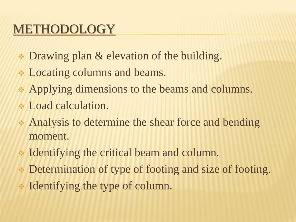
METHODOLOGY
Drawing plan & elevation of the building.
Locating columns and beams.
Applying dimensions to the beams and columns.
Load calculation.
Analysis to determine the shear force and bending
moment.
Identifying the critical beam and column.
Determination of type of footing and size of footing.
Identifying the type of column.

METHODOLOGY(CONTD)
Design of slab, beam, column and footing.
Performing respective checks for the corresponding
design.
Detailing of beam, column, beam column junctions and
footing.

PLAN

ELEVATION
FRONT ELEVATION REAR ELEVATION
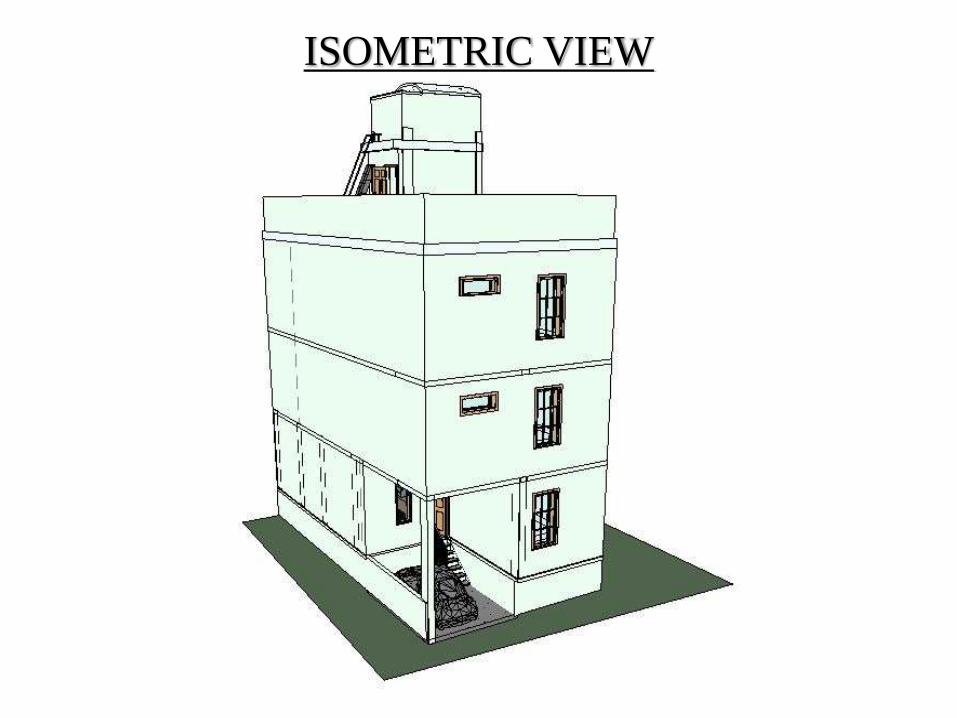
ISOMETRIC VIEW

TERRACE

COLUMN AND BEAM LOCATION
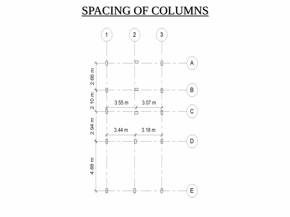
SPACING OF COLUMNS
LOADS
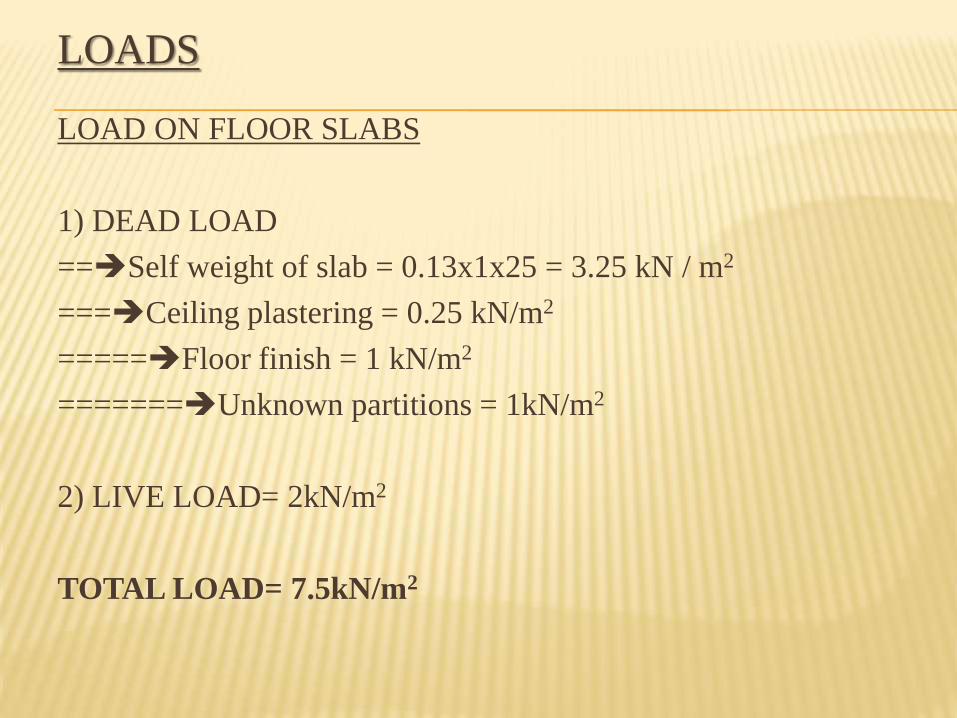
LOAD ON FLOOR SLABS
1) DEAD LOAD
==Self weight of slab = 0.13x1x25 = 3.25 kN / m2
===Ceiling plastering = 0.25 kN/m2
=====Floor finish = 1 kN/m2
=======Unknown partitions = 1kN/m2
2) LIVE LOAD= 2kN/m2
TOTAL LOAD= 7.5kN/m2

LOADS
LOAD ON ROOF SLAB
1) DEAD LOAD
==Self weight of slab = 0.13x1x25 = 3.25 kN / m2
===Ceiling plastering = 0.25 kN/m2
====Floor finish = 1 kN/m2
=====Weathering coarse 4 ½” = 2.19 kN/m2
2) LIVE LOAD = 1.5 kN/m2
TOTAL LOAD= 7.19 kN/m2

LOAD TRANSFERRED TO BEAM FROM SLAB
The load transferred to beam from slab is determined
by using triangular, trapezoidal & rectangular
formula.
Trapezoidal formula =W * Lx / 6 [ 3-( Lx/ Ly )2 ]
Triangular formula = W * Lx / 3
Rectangular formula = W * Lx / 2

LOAD DISTRIBUTION IN SLAB

CRITICALLY LOADED FRAME
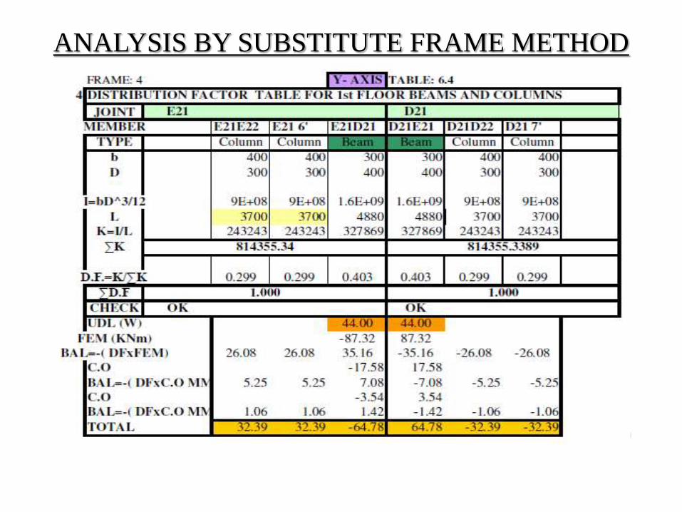
ANALYSIS BY SUBSTITUTE FRAME METHOD

DESIGN BENDING MOMENT FOR CRITICAL FRAME

SLAB DESIGN
Type of slab is identified by using ly/lx ratio.
Based on the ratio from IS 456:2000, momentcoefficients are obtained and moment is calculated.
Mx = αx wx lx2
My = αy wy lx2
Reinforcement is calculated by using,
Mu= 0.87 fy x Ast x d {1-( fy Ast)/(fckbd)}
For two way slab Ast for one direction is calculated and provided on both sides.
Torsional reinforcements are provided.

SLAB DETAILING

SLAB DETAILING (ONE WAY SLAB)

SLAB DETAILING (TWO WAY SLAB)
BEAM DESIGN
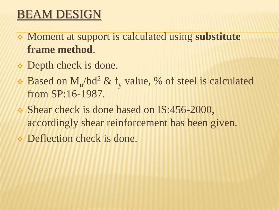
Moment at support is calculated using substitute
frame method.
Depth check is done.
Based on Mu/bd2 & fy value, % of steel is calculated
from SP:16-1987.
Shear check is done based on IS:456-2000,
accordingly shear reinforcement has been given.
Deflection check is done.

CRITICAL FRAME DETAILING

CRITICAL BEAM CROSS SECTION
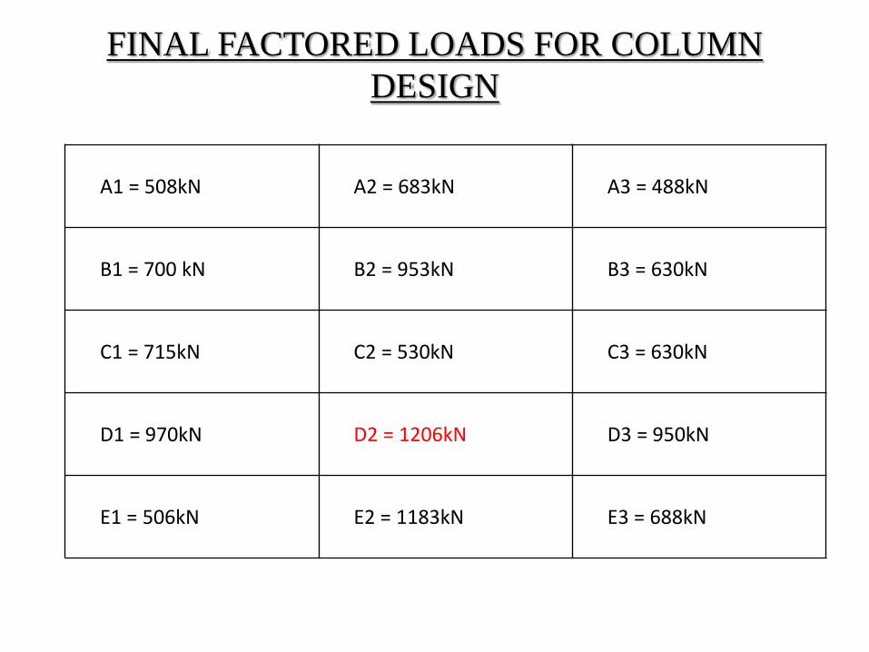
FINAL FACTORED LOADS FOR COLUMN
DESIGN
A1 = 508kN A2 = 683kN A3 = 488kN
B1 = 700 kN B2 = 953kN B3 = 630kN
C1 = 715kN C2 = 530kN C3 = 630kN
D1 = 970kN D2 = 1206kN D3 = 950kN
E1 = 506kN E2 = 1183kN E3 = 688kN

COLUMNS DESIGN
For axial columns Ast is calculated by using,
Pu = 0.4fckAc+ 0.67fyAsc
For uniaxial column the Ast is calculated using SP-16
1987 charts, based on the values of d’/D, Pu/fckbD &
Mu/fckbD2, the value of p/fck is determined, from
which % of steel can be calculated.

COLUMNS DESIGN (BIAXIAL)
<1, hence safe

COLUMN DETAILING

FOOTING DESIGN
Size of footing = 1.1 Wu/qs
=1.1(factored load)/safe bearing capacity
Depth of footing = √(Mu/0.133 fck b)
Provide, D = 2 X Dreq
Ast is calculated from,
Mu=0.87 fy x Ast x d {1-( fy Ast)/(fckbd)}
Check for one way shear and two way shear is done.
For rectangular footing central band reinforcement is
calculated and provided.

FACTORED LOAD ON FOOTING

FOOTING DIMENSIONS
All dimensions are in m

EDGE AND CORNER FOOTING
CORNER COLUMN FOOTING EDGE COLUMN FOOTING

FOOTING DETAIL
FOOTING FOR COLUMN E3 FOOTING FOR COLUMN E2

FOOTING DETAIL
FOOTING FOR COLUMN D2 FOOTING FOR COLUMN C2

CONCLUSION
Learnt
1) design of complete structure.
2) substitute frame method.
3) practical difficulties faced in field.
Was useful and will be helpful in our carrier.
Special mentions.
REFERENCE
Design of reinforced concrete structures -Ramamruthum.
Reinforced concrete design - Devdas Menon.
Theory of structures - B.C.Punmia.
Advanced design of reinforced concrete - Krishna Raju.
Design of G+3 building - Karve & Shah.
IS 456:2000.
SP:16 1987.
SP:34 1987.