Design of the “Resource Allocation” field in the Basic Assignment A-MAP IE: Simulation results,...
18
Design of the “Resource Allocation” field in the Basic Assignment A-MAP IE: Simulation results, Insights & Methodology Document Number: IEEE C80216m-09_0917r2 Date Submitted: 2009-04-27 Source: Sudhir Ramakrishna E-mail: [email protected] Youngbo Cho Zhouyue Pi Hyunkyu Yu Samsung Electronics Venue: Re: 802.16m amendment working document Category: AWD Comments Area: Chapter 15.3.6 (DL Control) Base Contribution: IEEE C80216m-09_0917r2 Purpose: To be discussed and adopted by TGm for the 802.16m AWD Notice: This document does not represent the agreed views of the IEEE 802.16 Working Group or any of its subgroups. It represents only the views of the participants listed in the “Source(s)” field above. It is offered as a basis for discussion. It is not binding on the contributor(s), who reserve(s) the right to add, amend or withdraw material contained herein. Release: The contributor grants a free, irrevocable license to the IEEE to incorporate material contained in this contribution, and any modifications thereof, in the creation of an IEEE Standards publication; to copyright in the IEEE’s name any IEEE Standards publication even though it may include portions of this contribution; and at the IEEE’s sole discretion to permit others to reproduce in whole or in part the resulting IEEE Standards publication. The contributor also acknowledges and accepts that this contribution may be made public by IEEE 802.16. Patent Policy: The contributor is familiar with the IEEE-SA Patent Policy and Procedures:
-
Upload
jade-taylor -
Category
Documents
-
view
217 -
download
0
Transcript of Design of the “Resource Allocation” field in the Basic Assignment A-MAP IE: Simulation results,...
Design of the “Resource Allocation” field in the Basic Assignment A-MAP IE: Simulation results, Insights & Methodology
Document Number:IEEE C80216m-09_0917r2
Date Submitted:2009-04-27
Source:Sudhir Ramakrishna E-mail: [email protected] Youngbo ChoZhouyue PiHyunkyu Yu
Samsung Electronics
Venue:Re: 802.16m amendment working document Category: AWD CommentsArea: Chapter 15.3.6 (DL Control)
Base Contribution:IEEE C80216m-09_0917r2
Purpose:To be discussed and adopted by TGm for the 802.16m AWDNotice:
This document does not represent the agreed views of the IEEE 802.16 Working Group or any of its subgroups. It represents only the views of the participants listed in the “Source(s)” field above. It is offered as a basis for discussion. It is not binding on the contributor(s), who reserve(s) the right to add, amend or withdraw material contained herein.
Release:The contributor grants a free, irrevocable license to the IEEE to incorporate material contained in this contribution, and any modifications thereof, in the creation of an IEEE Standards publication; to copyright in the IEEE’s name any IEEE Standards publication even though it may include portions of this contribution; and at the IEEE’s sole discretion to permit others to reproduce in whole or in part the resulting IEEE Standards publication. The contributor also acknowledges and accepts that this contribution may be made public by IEEE 802.16.
Patent Policy:The contributor is familiar with the IEEE-SA Patent Policy and Procedures:
<http://standards.ieee.org/guides/bylaws/sect6-7.html#6> and <http://standards.ieee.org/guides/opman/sect6.html#6.3>.Further information is located at <http://standards.ieee.org/board/pat/pat-material.html> and <http://standards.ieee.org/board/pat >.
IEEE C80216m-09_0917r2 Slide #2
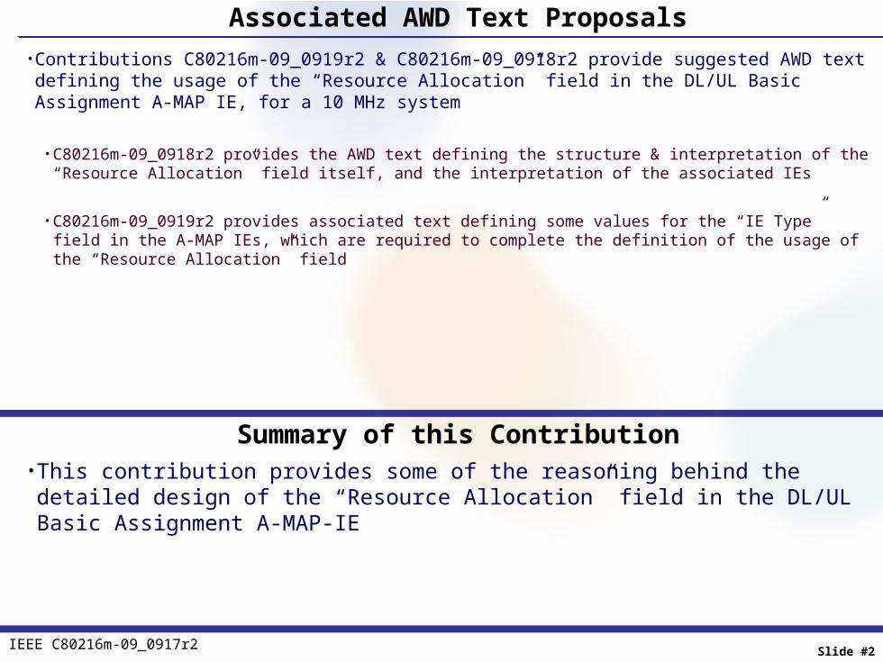
Associated AWD Text Proposals• Contributions C80216m-09_0919r2 & C80216m-09_0918r2 provide suggested AWD text defining the
usage of the “Resource Allocation” field in the DL/UL Basic Assignment A-MAP IE, for a 10 MHz system
• C80216m-09_0918r2 provides the AWD text defining the structure & interpretation of the “Resource Allocation” field itself, and the interpretation of the associated IEs
• C80216m-09_0919r2 provides associated text defining some values for the “IE Type” field in the A-MAP IEs, which are required to complete the definition of the usage of the “Resource Allocation” field
Summary of this Contribution• This contribution provides some of the reasoning behind the detailed design of the “Resource Allocation”
field in the DL/UL Basic Assignment A-MAP-IE

IEEE C80216m-09_0917r2 Slide #3
Design of the “Resource Allocation” field to indicate DRU Resources

IEEE C80216m-09_0917r2 Slide #4
RA Field for DRU Resource Indication – Design Goals• Only contiguous indices need to be indicated• Should be possible to indicate a 1 DRU assignment• There should be no un-occupied DRUs due to assignment limitation• For VoIP support, should be able to indicate assignment of 1/2/3/4 & 6 DRUs
RA Field for DRU Resource Indication – Design Summary• Size of RA Field : 8 bits in a 10 MHz system• Use a channel-tree (combination of triangular and power-of-2 branches) with 252 nodes to indicate
assignment of particular set of contiguous DRU indices

IEEE C80216m-09_0917r2 Slide #5
RA Field for DRU Indication: Resource Indication “Tree”
252 nodes in tree 8 bits sufficient to indicate any particular node (in 10 MHz)
Node indicated by RA field allocates all bottom-level- LRU-nodes that originate from it

IEEE C80216m-09_0917r2 Slide #6
RA Field for DRU Indication : Possible Indications with “Tree”
Available LRU size
Assignment LRU indices
1
{0}, {1}, {2}, {3}, {4}, {5}, {6}, {7}, {8}, {9}, {10}, {11}, {12}, {13}, {14}, {15}, {16}, {17}, {18}, {19}, {20}, {21}, {22}, {23}, {24}, {25}, {26}, {27}, {28}, {29}, {30}, {31}, {32}, {33}, {34}, {35}, {36}, {37}, {38}, {39}, {40}, {41}, {42}, {43}, {44}, {45}, {46}, {47}
2
{0, 1}, {1, 2}, {2, 3}, {3, 4}, {4, 5}, {5, 6}, {6, 7}, {7, 8}, {8, 9}, {9, 10}, {10, 11}, {11, 12}, {12, 13}, {13, 14}, {14, 15}, {15, 16}, {16, 17}, {17, 18}, {18, 19}, {19, 20}, {20, 21}, {21, 22}, {22, 23}, {23, 24}, {24, 25}, {25, 26}, {26, 27}, {27, 28}, {28, 29}, {29, 30}, {30, 31}, {31, 32}, {32, 33}, {33, 34}, {34, 35}, {35, 36}, {36, 37}, {37, 38}, {38, 39}, {39, 40}, {40, 41}, {41, 42}, {42, 42}, {43, 44}, {44, 45}, {45, 46}, {46, 47}
3
{0 ~ 2}, {1 ~ 3}, {2 ~ 4}, {3 ~ 5}, {4 ~ 6}, {5 ~ 7}, {6 ~ 8}, {7 ~ 9}, {8 ~ 10}, {9 ~ 11}, {10 ~ 12}, {11 ~ 13}, {12 ~ 14}, {13 ~ 15}, {14 ~ 16}, {15 ~ 17}, {16 ~ 18}, {17 ~ 19}, {18 ~ 20}, {19 ~ 21}, {20 ~ 22}, {21 ~ 23}, {22 ~ 24}, {23 ~ 25}, {24 ~ 26}, {25 ~ 27}, {26 ~ 28}, {27 ~ 29}, {28 ~ 30}, {29 ~ 31}, {30 ~ 32}, {31 ~ 33}, {32 ~ 34}, {33 ~ 35}, {34 ~ 36}, {35 ~ 37}, {36 ~ 38}, {37 ~ 39}, {38 ~ 40}, {39 ~ 41}, {40 ~ 42}, {41 ~ 43}, {42 ~ 44}, {43 ~ 45}, {44 ~ 46}, {45 ~ 47}
4
{0 ~ 3}, {2 ~ 5}, {4 ~ 7}, {6 ~ 9}, {8 ~ 11}, {10 ~ 13}, {12 ~ 15}, {14 ~ 17}, {16 ~ 19}, {18 ~ 21}, {20 ~ 23}, {22 ~ 25}, {24 ~ 27}, {26 ~ 29}, {28 ~ 31}, {30 ~ 33}, {32 ~ 35}, {34 ~ 37}, {36 ~ 39}, {38 ~ 41}, {40 ~ 43}, {42 ~ 45}, {44 ~ 47}
6
{0 ~ 5}, {2 ~ 7}, {4 ~ 9}, {6 ~ 11}, {8 ~ 13}, {10 ~ 15}, {12 ~ 17}, {14 ~ 19}, {16 ~ 21}, {18 ~ 23}, {20 ~ 25}, {22 ~ 27}, {24 ~ 29}, {26 ~ 31}, {28 ~ 33}, {30 ~ 35}, {32 ~ 37}, {34 ~ 39}, {36 ~ 41}, {38 ~ 43}, {40 ~ 45}, {41 ~ 47}
8 {0 ~ 7}, {4 ~ 11}, {8 ~ 15}, {12 ~ 19}, {16 ~ 23}, {20 ~ 27}, {24 ~ 31}, {28 ~ 35}, {32 ~ 39}, {36 ~ 43}, {40 ~ 47}
12 {0 ~ 11}, {4 ~ 15}, {8 ~ 19}, {12 ~ 23}, {16 ~ 27}, {20 ~ 31}, {24 ~ 35}, {28 ~ 39}, {32 ~ 43}, {36 ~ 47}
16 {0 ~ 15}, {4 ~ 19}, {8 ~ 23}, {12 ~ 27}, {16 ~ 31}, {20 ~ 35}, {24 ~ 39}, {28 ~ 43}, {32 ~ 47}
20 {0 ~ 19}, {4 ~ 23}, {8 ~ 27}, {12 ~ 31}, {16 ~ 35}, {20 ~ 39}, {24 ~ 43}, {28 ~ 47}
24 {0 ~ 23}, {4 ~ 27}, {8 ~ 31}, {12 ~ 35}, {16 ~ 39}, {20 ~ 43}, {24 ~ 47} 28 {0 ~ 27}, {4 ~ 31}, {8 ~ 35}, {12 ~ 39}, {16 ~ 43}, {20 ~ 47} 32 {0 ~ 31}, {4 ~ 35}, {8 ~ 39}, {12 ~ 43}, {16 ~ 47} 36 {0 ~ 35}, {4 ~ 39}, {8 ~ 43}, {12 ~ 47} 40 {0 ~ 39}, {4 ~ 43}, {8 ~ 47} 44 {0 ~ 43}, {4 ~ 47} 48 {0 ~ 47}

IEEE C80216m-09_0917r2 Slide #7
Design of the “Resource Allocation” field to indicate sub-band-based CRU
Resources – Motivating DL System Level Simulation Results

IEEE C80216m-09_0917r2 Slide #8
DL System Level Simulation Summary• 10 MHz FDD DL system Total of 48 PRUs, 8 DL sub-frames per 5ms frame, Sub-band CRUs only• Full blown system-level simulator - 57 sectors with wrap-around, 10 users per sector (hence 570 users
total), all action modeled in all sectors• 2 uncorrelated transmit antennas at each sector, 2 uncorrelated receive antennas at each mobile• Channel modeling
• Each sector-antenna to mobile-antenna link modeled by a 24-tap model (2 cases - EMD Modified Ped B, 3 Kmph model & EMD Modified Vehicular A, 30 Kmph model)
• CQI/PMI calculation, once every frame• For each mobile, “best” PMI/# of streams/LMMSE CQI calculated for each sub-band
• Calculation takes into account precoding being used in all interfering sectors (hence “flashlight” effect captured)• “Best” based on exhaustive search over all pre-coders/# of streams
• Using the 3-bit 16e rank1 and rank 2 codebooks
• Scheduling, every sub-frame• For each mobile, a priority is assigned to each sub-band based on the PF metric, using the CQI for the sub-band• “Greedy” PF : Mobiles are assigned sub-bands in priority order; no limit on # of sub-bands per-mobile per-sub-frame• MCS selection driven by average CQI across all assigned sub-bands, re-transmissions use same MCS
• Using the LTE TFs (9 MCSs)
• Packet performance evaluation : LMMSE SINR formula takes interference from all sectors feeds into EESM method for packet success/failure determination

IEEE C80216m-09_0917r2 Slide #9
# of sub-bands per-average-mobile per-sub-frame statistics, 1/2
• Statistic logged• During the simulation, for each mobile, record the number of times X sub-bands were assigned, X = 1 to 12
• For mobile i, let ni(X) be the # of times X sub-bands were assigned, X = 1 to 12
• At the end of the simulation, for each value of X sub-bands (X = 1 to 12), calculate the # of occurrences over all mobiles
• N(X) = ∑ ni(X), where the sum is taken over all mobiles in the system
• Then, calculate the PDF of the assignment of X sub-bands (X = 1 to 12) to an “average” mobile as • p(X) = N(X)/{ N(1) + N(2) + N(3) + … + N(12) }
• This statistic gives us insight into the # of sub-bands that are assigned most often

IEEE C80216m-09_0917r2 Slide #10
# of sub-bands per-average-mobile per-sub-frame statistics, 2/2
• Insights• Assignment of a small number of sub-bands dominates the set of assignments
• Assignment of <= 2 sub-bands accounts for ~ 84% and 77% of all assignments in PedB3 and VehA30, respectively• Assignment of <=3 sub-bands accounts for ~94% and 87% of all assignments in PedB3 and VehA30, respectively

IEEE C80216m-09_0917r2 Slide #11
Contiguous vs non-countiguous sub-band assignments, 1/2
• Statistic logged• During the simulation, for each mobile, whenever it is assigned X > 1 sub-bands
• The X sub-bands are selected from the PF algorithm and are, in general, non-contiguous• The MCS assigned is driven by the average CQI over the X sub-bands; let this value be CQI_avg_actual• Calculate the average CQI over X sub-bands, if the X sub-bands were chosen to have logically contiguous indices. Let this value
be CQI_avg_contiguous • Log the ratio CQI_avg_actual/ CQI_avg_contiguous for each value of X, X = 2 to 12• At the end of simulation, for each mobile, calculate the average value of CQI_avg_actual/ CQI_avg_contiguous for each value of
X, X = 2 to 12• Plot the CDF of this average ratio, for various values of allocated sub-bands X.
• This statistic yield insights into the importance of designing the IEs to allow for non-contiguous (w.r.t logical indices) sub-band assignments

IEEE C80216m-09_0917r2 Slide #12
Contiguous vs non-contiguous sub-band assignments, 2/2
• Insights• The gain of non-contiguous allocations (over contiguous allocations) does not appear to be large
• Caveat 1 : More frequency selective channel models may yield different results• Caveat 2 : In PedB3, between 10% (for 2 sub-band allocations) and 30% (for 3/4/5 sub-band allocations) of the users see CQI
ratios larger than 1 dB (corresponding fractions for VehA30 are much larger)• The SINRs corresponding to the 1% FER point in the MCSs in the16m MCS table are planned to be ~ 1dB apart• Hence, contiguous allocations in these cases would lead to lower MCSs being selected and lower throughputs
• Caveat 3 : The instantaneous ratio in any assignment could be larger than the average (which is plotted in CDF) • Gains of non-contiguous allocations seem “surer” (narrower CDF) for smaller number of assigned sub-bands
• Reason – When assigning larger # of sub-bands, less chance of getting the highest PF priority non-contiguous sub-bands
IEEE C80216m-09_0917r2 Slide #13
Common MCS vs different MCSs across allocated sub-bands, 1/2
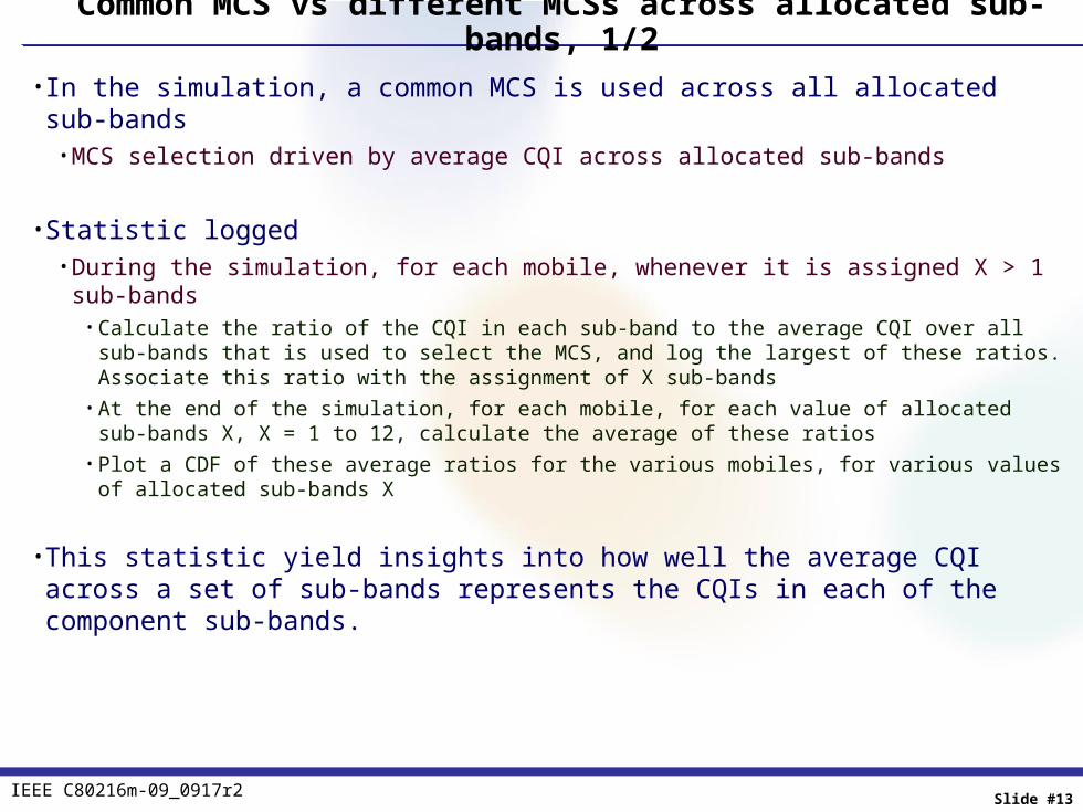
• In the simulation, a common MCS is used across all allocated sub-bands• MCS selection driven by average CQI across allocated sub-bands
• Statistic logged• During the simulation, for each mobile, whenever it is assigned X > 1 sub-bands
• Calculate the ratio of the CQI in each sub-band to the average CQI over all sub-bands that is used to select the MCS, and log the largest of these ratios. Associate this ratio with the assignment of X sub-bands
• At the end of the simulation, for each mobile, for each value of allocated sub-bands X, X = 1 to 12, calculate the average of these ratios
• Plot a CDF of these average ratios for the various mobiles, for various values of allocated sub-bands X
• This statistic yield insights into how well the average CQI across a set of sub-bands represents the CQIs in each of the component sub-bands.

IEEE C80216m-09_0917r2 Slide #14
Common MCS vs different MCSs across allocated sub-bands, 2/2
• Insights• When smaller # of sub-bands (2, 3) are allocated, the average CQI across sub-bands is close to the individual sub-
band CQIs• When a larger # of sub-bands is allocated, more deviation of sub-band CQI from the average• However, from previous result, a small # of sub-bands (1/2/3) is most likely to be allocated• Hence, a common MCS across sub-bands, based on the average CQI across sub-bands, should suffice
IEEE C80216m-09_0917r2 Slide #15
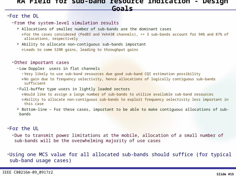
RA Field for sub-band resource indication - Design Goals• For the DL
• From the system-level simulation results Allocations of smaller number of sub-bands are the dominant cases
o For the cases considered (PedB3 and VehA30 channels), <= 3 sub-bands account for 94% and 87% of allocations, respectively Ability to allocate non-contiguous sub-bands important
o Leads to some SINR gains, leading to throughput gains
• Other important cases• Low Doppler users in flat channels
• Very likely to use sub-band resources due good sub-band CQI estimation possibilityo No gain due to frequency selectivity, hence allocations of logically contiguous sub-bands sufficient
• Full-buffer type users in lightly loaded sectorso Would like to assign a large number of sub-bands to utilize available sub-band resourceso Ability to allocate non-contiguous sub-bands to exploit frequency selectivity less important in this case
Bottom-line – For these cases, important to be able to make contiguous allocations of sub-bands
• For the UL• Due to transmit power limitations at the mobile, allocation of a small number of sub-bands will be the overwhelming
majority of use cases
• Using one MCS value for all allocated sub-bands should suffice (for typical sub-band usage cases)

IEEE C80216m-09_0917r2 Slide #16
RA Field to assign sub-band resources – Design Summary• RA Field size – 8 bits for a 10 MHz system (Same size as for the DRU assignment indication)
• Identical structure and interpretation rules for the DL and UL• RA Field interpretation assisted by the “IE Type” field
• 0x0 DL Basic Assignment IE, indicating allocation with non-contiguous logical indices• 0x2 DL Basic Assignment IE, indicating allocation with contiguous logical indices • Similar set of values to indicate UL assignments
• Assignment granularity is 1 sub-band
• RA Field interpretations defined such that with 1 IE, can indicate assignment of• Any 1 sub-band• Any combination of 2 sub-bands • Almost all combinations of 3 sub-bands• Arbitrary numbers of sub-bands with contiguous indices Leverage the RA indication for the DRU case
• For combinations that cannot be indicated by 1 IE, proposed solution• Convey the assignment in 2 IEs• Rules are defined to combine the RA fields in the 2 IEs to allow arbitrary sub-band allocations
• 2 IEs is the maximum number of IEs needed to convey all possible sub-band allocations in 10 MHz

IEEE C80216m-09_0917r2 Slide #17
RA Field Interpretation Summary (DL)
IEEE C80216m-09_0917r2 Slide #18
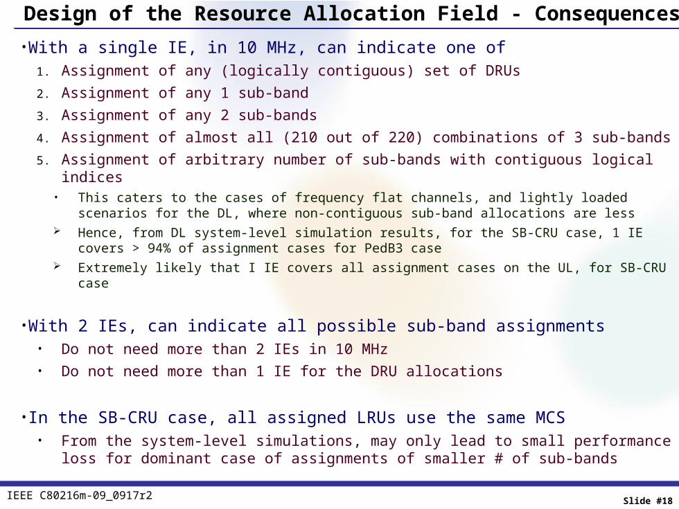
Design of the Resource Allocation Field - Consequences• With a single IE, in 10 MHz, can indicate one of
1. Assignment of any (logically contiguous) set of DRUs2. Assignment of any 1 sub-band3. Assignment of any 2 sub-bands4. Assignment of almost all (210 out of 220) combinations of 3 sub-bands5. Assignment of arbitrary number of sub-bands with contiguous logical indices
• This caters to the cases of frequency flat channels, and lightly loaded scenarios for the DL, where non-contiguous sub-band allocations are less
Hence, from DL system-level simulation results, for the SB-CRU case, 1 IE covers > 94% of assignment cases for PedB3 case Extremely likely that I IE covers all assignment cases on the UL, for SB-CRU case
• With 2 IEs, can indicate all possible sub-band assignments• Do not need more than 2 IEs in 10 MHz• Do not need more than 1 IE for the DRU allocations
• In the SB-CRU case, all assigned LRUs use the same MCS• From the system-level simulations, may only lead to small performance loss for dominant case of assignments of
smaller # of sub-bands