Design of Structures for Earthquake...
17
NATIONAL TECHNICAL UNIVERSITY OF ATHENS LABORATORY OF EARTHQUAKE ENGINEERING Design of Structures for Earthquake Resistance Basic principles Ioannis N. Psycharis Lecture 2
Transcript of Design of Structures for Earthquake...

NATIONAL TECHNICAL UNIVERSITY OF ATHENS LABORATORY OF EARTHQUAKE ENGINEERING
Design of Structures for
Earthquake Resistance
Basic principles
Ioannis N. Psycharis
Lecture 2

NATIONAL TECHNICAL UNIVERSITY OF ATHENS Ioannis Psycharis
LABORATORY OF EARTHQUAKE ENGINEERING Design of Structures for Earthquake Resistance - Basic principles
unacceptable
Performance levels
● Define earthquake loadings with various probabilities of
occurrence
● Define various acceptable level of damage
● Combine each earthquake loading with an acceptable level of
damage Performance level
Very small
damage Damage
limitation level
Significant damage
Collapse prevention
Close to collapse
Fre
quency o
f occurre
nce o
f the
seis
mic
excita
tion
Large
Frequent earthquakes
Small
Rare earthquakes
Very small
Very rare earthquakes

NATIONAL TECHNICAL UNIVERSITY OF ATHENS Ioannis Psycharis
LABORATORY OF EARTHQUAKE ENGINEERING Design of Structures for Earthquake Resistance - Basic principles
Performance requirements of seismic codes
Most codes are based on two performance levels:
● Damage limitation level
♦ The structure is expected to experience limited structural
and non-structural damage during frequent earthquakes.
In this limit state:
▪ The structural members retain their strength and
stiffness.
▪ No permanent deformations and drifts occur.
▪ No repair is needed.
♦ The seismic action is usually termed as the serviceability
earthquake. Reasonable probability of exceedance = 10%
in 10 years (mean return period = 95 years).
♦ Compliance criteria are usually expressed in terms of
deformation limits.
NATIONAL TECHNICAL UNIVERSITY OF ATHENS Ioannis Psycharis
LABORATORY OF EARTHQUAKE ENGINEERING Design of Structures for Earthquake Resistance - Basic principles
Performance requirements of seismic codes
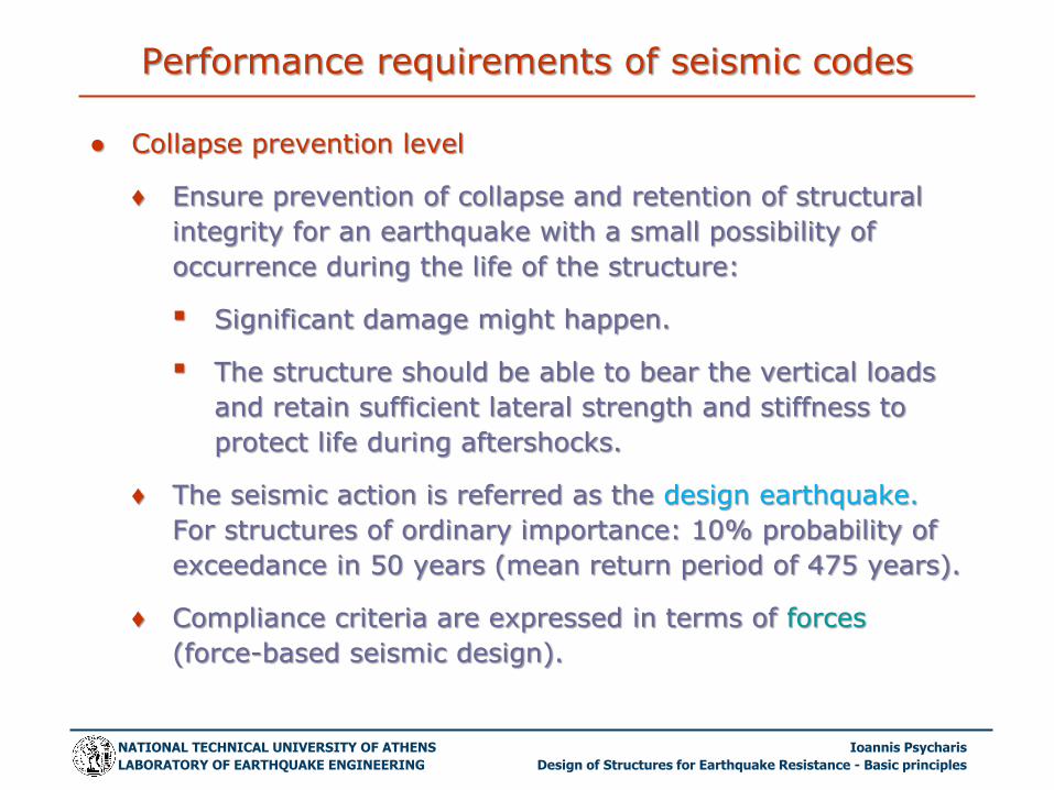
● Collapse prevention level
♦ Ensure prevention of collapse and retention of structural
integrity for an earthquake with a small possibility of
occurrence during the life of the structure:
▪ Significant damage might happen.
▪ The structure should be able to bear the vertical loads
and retain sufficient lateral strength and stiffness to
protect life during aftershocks.
♦ The seismic action is referred as the design earthquake.
For structures of ordinary importance: 10% probability of
exceedance in 50 years (mean return period of 475 years).
♦ Compliance criteria are expressed in terms of forces
(force-based seismic design).

NATIONAL TECHNICAL UNIVERSITY OF ATHENS Ioannis Psycharis
LABORATORY OF EARTHQUAKE ENGINEERING Design of Structures for Earthquake Resistance - Basic principles
Period, T
0.0
0.5
1.0
1.5
2.0
2.5
Sa /
(S
ag
R)
TB TC TD0
Design concept
● The structure is designed to behave
elastically up to a level of seismic forces
lower than the one required for fully elastic
response.
● The loads corresponding to the
design seismic action are derived by
dividing the elastic ones by a
reduction factor denoted by
♦ R (reduction factor) or
♦ q (behaviour factor).
1:q
1:q
How is q defined?

NATIONAL TECHNICAL UNIVERSITY OF ATHENS Ioannis Psycharis
LABORATORY OF EARTHQUAKE ENGINEERING Design of Structures for Earthquake Resistance - Basic principles
Ductility capacity
● The collapse mechanism of the structural members is related
to their deformation and not to the forces induced to them
during the seismic action.
● In order to comply with the non-collapse criterion, an overall
ductile behaviour should be ensured.
● In other words: the structure should have an adequate
capacity to deform beyond its elastic limit without substantial
reduction in the overall resistance against horizontal and
vertical loads.
● This is achieved through proper dimensioning and detailing of
the structural elements.
● In addition, capacity design concepts are applied, in order to
ensure that ductile modes of failure (e.g. flexure) should
precede brittle modes of failure (e.g. shear) with sufficient
reliability.

NATIONAL TECHNICAL UNIVERSITY OF ATHENS Ioannis Psycharis
LABORATORY OF EARTHQUAKE ENGINEERING Design of Structures for Earthquake Resistance - Basic principles
Nonlinear response
Force-deformation relation
Elastoplastic idealization
Same area under the two curves

NATIONAL TECHNICAL UNIVERSITY OF ATHENS Ioannis Psycharis
LABORATORY OF EARTHQUAKE ENGINEERING Design of Structures for Earthquake Resistance - Basic principles
Basic definitions
● Yield strength behaviour factor:
𝑞𝑦 =𝑓𝑒𝑓𝑦
● Ductility factor:
𝜇 =𝑢𝑚𝑢𝑦
● It can easily be proved:
𝑢𝑚𝑢𝑒=𝜇
𝑞𝑦
● As larger is μ as larger is the plastic deformation more
damage.
● For μ close to 1, the response is close to the elastic.
fs
u
fy
uy um
fe
ue

NATIONAL TECHNICAL UNIVERSITY OF ATHENS Ioannis Psycharis
LABORATORY OF EARTHQUAKE ENGINEERING Design of Structures for Earthquake Resistance - Basic principles
Inelastic response spectra
Inelastic spectra for constant ductility
0.0 0.2 0.4 0.6 0.8 1.0 1.2 1.4 1.6 1.8 2.0
Ιδιοπερίοδος, Τ (sec)
0.0
1.0
2.0
3.0
4.0
5.0
6.0
7.0
8.0
Eπιτάχυνση
διαρροής,
ay (
m/s
ec
2)
ΑΝΕΛΑΣΤΙΚΑ ΦΑΣΜΑΤΑμ=1
μ=1.5
μ=2
μ=3
μ=5
μ=8
INELASTIC SPECTRA
Period, T (sec)
Yie
ld A
cce
lera
tio
n (
m/s
ec
2)

NATIONAL TECHNICAL UNIVERSITY OF ATHENS Ioannis Psycharis
LABORATORY OF EARTHQUAKE ENGINEERING Design of Structures for Earthquake Resistance - Basic principles
Ductility factor
● The damage that will be induced to the structure is directly
related to the ductility factor, μ.
● For the non-collapse performance criterion, certain values can
be assigned to the allowable maximum value of μ, depending
on:
♦ The material (ductile or brittle).
♦ The structural system (the more isostatic is the structure
the less is the allowable value of μ).
♦ The structural irregularities in plan or in elevation and the
torsional sensitivity (reduce the allowable value of μ).
♦ The connections and the bracing types (steel structures).
NATIONAL TECHNICAL UNIVERSITY OF ATHENS Ioannis Psycharis
LABORATORY OF EARTHQUAKE ENGINEERING Design of Structures for Earthquake Resistance - Basic principles
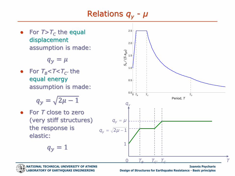
Relations qy - μ
● For T>TC the equal
displacement
assumption is made:
𝑞𝑦 = 𝜇
● For TB<T<TC’ the
equal energy
assumption is made:
𝑞𝑦 = 2𝜇 − 1
● For T close to zero
(very stiff structures)
the response is
elastic:
𝑞𝑦 = 1
Period, T
0.0
0.5
1.0
1.5
2.0
2.5
Sa /
(S
ag
R)
TB TC TD0
qy
T TC TC’ TB
1
μqy
12 μqy
0

NATIONAL TECHNICAL UNIVERSITY OF ATHENS Ioannis Psycharis
LABORATORY OF EARTHQUAKE ENGINEERING Design of Structures for Earthquake Resistance - Basic principles
Design value of q
Design value of the behaviour factor:
𝑞 = 𝛾𝑅𝑑 ∙ 𝑞𝑦
(γRd= overstrength)
● Usually, rigid
structures possess
larger overstrength
than flexible ones
we usually assume
constant value of q for
T>TB.
T TC TC’ TB
1
μqy
12 μqy
q Period, T
0.0
0.5
1.0
1.5
2.0
2.5
Sa /
(S
ag
R)
TB TC TD0
1:q
1:q
qy
q
γRd γRd

NATIONAL TECHNICAL UNIVERSITY OF ATHENS Ioannis Psycharis
LABORATORY OF EARTHQUAKE ENGINEERING Design of Structures for Earthquake Resistance - Basic principles
Ductility classes (EC8)
● Ductility Class High (DCH)
♦ Strict detailing criteria should be fulfilled.
♦ Provides higher safety margins against local or global
collapse under seismic actions stronger than the design
earthquake.
● Ductility Class Medium (DCM)
♦ Compared to DCH, certain detailing rules are relaxed.
♦ The design leads to slightly easier to construct structures.
♦ Provides good performance during moderate earthquakes.
● Ductility Class Low (DCL)
♦ For low seismicity areas.
♦ The structure is designed according to EC2 without special
seismic considerations.
♦ Large values of q are allowed.

NATIONAL TECHNICAL UNIVERSITY OF ATHENS Ioannis Psycharis
LABORATORY OF EARTHQUAKE ENGINEERING Design of Structures for Earthquake Resistance - Basic principles
Proper detailing
Aims to:
♦ provide the structure with an adequate capacity to deform
beyond its elastic limit without substantial reduction of the
overall resistance against horizontal and vertical loads.
Example for concrete structures:
Special rules are applied for the confinement reinforcement
(stirrups) at column-to-beam joints and at critical regions of
columns and beams.

NATIONAL TECHNICAL UNIVERSITY OF ATHENS Ioannis Psycharis
LABORATORY OF EARTHQUAKE ENGINEERING Design of Structures for Earthquake Resistance - Basic principles
Capacity design
Aims to:
♦ ensure that ductile modes of failure (e.g. flexure) should
precede brittle modes of failure (e.g. shear) with sufficient
reliability
♦ prevent the formation of a soft-story mechanism
♦ ensure that certain parts of the structure will remain elastic if
it is so desired (e.g. foundation, bridge deck, etc.)
Example for concrete structures:
At column-to-beam joints, the sum of the design values of the
moments of resistance of the columns should be larger than
1.3the sum of the design values of the moments of resistance of
the beams: 𝑀𝑅𝑐 ≥ 1.3 ∙ 𝑀𝑅𝑏

NATIONAL TECHNICAL UNIVERSITY OF ATHENS Ioannis Psycharis
LABORATORY OF EARTHQUAKE ENGINEERING Design of Structures for Earthquake Resistance - Basic principles
Design procedure
● Define the seismic loads for:
♦ The appropriate seismicity, the soil conditions at the site
and the importance of the structure.
♦ The appropriate value of the behaviour factor, q
▪ Material
▪ Structural system
▪ Irregularites
▪ Ductility class
● Perform a structural analysis of the structure for the seismic
and non-seismic loads, assuming elastic response.
● Combine the individual load cases according to the code
provisions to get the envelop of the member loads.

NATIONAL TECHNICAL UNIVERSITY OF ATHENS Ioannis Psycharis
LABORATORY OF EARTHQUAKE ENGINEERING Design of Structures for Earthquake Resistance - Basic principles
Design procedure (cont’d)
● Perform the dimensioning of the beams in flexure.
● Check the beams in shear using the capacity design approach
(based on the flexural strength of the beams).
● Perform the dimensioning of the columns in flexure using the
capacity design approach (based on the flexural strength of
the beams framing with the columns at the joints).
● Check columns in shear using the capacity design approach
(based on the flexural strength of the columns).
● Perform a detailed dimensioning of the joints in order to
assure their integrity during the design earthquake.
● Perform the dimensioning of the foundation using the capacity
design approach (based on the flexural strength of the
columns).
● Design displacements: d = qdE, dE = from seismic analysis.