Design of Reinforced Concrete Structures Prof. N. Dhang...
19
Design of Reinforced Concrete Structures Prof. N. Dhang Department of Civil Engineering Indian Institute of Technology, Kharagpur Lecture - 07 Limit State of Collapse Flexure II (Refer Slide Time: 01:04) Today, we shall continue limit state of collapse flexure part 2. So, that is our lecture 07 limit state of collapse flexure part 2. (Refer Slide Time: 01:36)
Transcript of Design of Reinforced Concrete Structures Prof. N. Dhang...

Design of Reinforced Concrete Structures
Prof. N. Dhang
Department of Civil Engineering
Indian Institute of Technology, Kharagpur
Lecture - 07
Limit State of Collapse Flexure II
(Refer Slide Time: 01:04)
Today, we shall continue limit state of collapse flexure part 2. So, that is our lecture 07
limit state of collapse flexure part 2.
(Refer Slide Time: 01:36)

Last class, we have done started we have started limit state of collapse flexure singly
reinforced section that where reinforcement in the tension side stress-strain curve the
strain diagram and the corresponding stress diagram. The ultimate strain in steel it is
dependent on fy we shall get epsilon su equal to 0.87fy taking 1.15 as the partial safety
factor for materials. So, 0.87fy by Es plus 002.
We have also done the problem if we know I shall show you that expression of resistance
moment for a balanced section. In terms of fy and p we have derived the equations in the
last class.
(Refer Slide Time: 02:45)
Today, we shall start expression for resistance moment in terms of concrete strength fck
Mu equal to 0.36fck times x times. This is the compressive force multiplied by d minus
let us put it 0.42 x we can put it 0.41 x we can also find out point four x also in different
books. But, we shall take let us take here 0.42 x 0.36fck times x multiplied by bd times 1
minus 0.42 x by d.
We can further write down, 0.36fck x by d times 1 minus 0.42 x by d times bd square.
So, here bd another d is coming from here x by d. So, we can get this is 1 expression we
can consider or we can we can write down in this fashion also 0.36 x by d multiplied by
1 minus 0.42 x by d times fck bd square.
This is 1 term 1 36 x by d times 1 minus 0.42 x by d fck bd square, for different grade of
concrete we shall get this is dependent on this fck. We can also write down say K fck bd
square. Further we can write down Mu by bd square equal to k fck we shall get Mu by bd
square equal to K fck we can refer annex G of IS 456 2000. So, Mu by bd square k fck
where k is nothing, but 0.36 x by d 1 minus 0.42 x by d.
(Refer Slide Time: 07:15)
So, let continue for Fe 415 xu by that is the limiting value that we have seen equal to
0.48. Therefore, Mu equal to 0.36 xu by d multiplied by 1 minus zero 0.42 xu by d times
fck bd square. Which comes as 0.36 multiplied by 0.48 multiplied by 1 minus 0.42 times
let me put it this way 0.48fck bd square, which results 0.138fck bd square. So, for
concrete grade for M 20 we can multiply 20 we shall get the resistance for concrete for a
particular grade section.
(Refer Slide Time: 08:48).
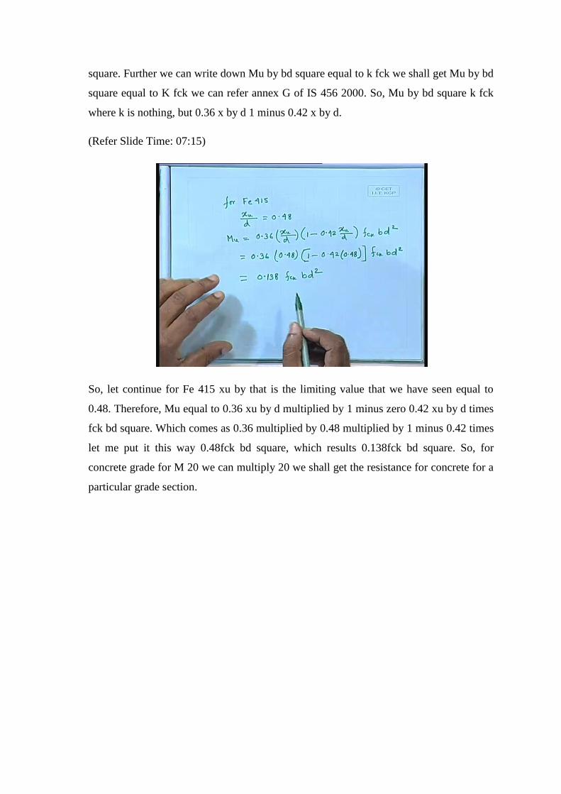
Next, we shall come steel area for balanced singly reinforced section.
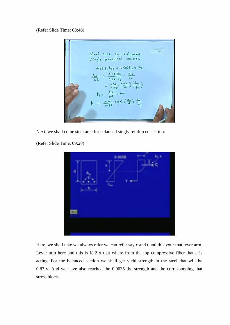
(Refer Slide Time: 09:28)
Here, we shall take we always refer we can refer say c and t and this your that lever arm.
Lever arm here and this is K 2 x that where from the top compressive fiber that c is
acting. For the balanced section we shall get yield strength in the steel that will be
0.87fy. And we have also reached the 0.0035 the strength and the corresponding that
stress block.

We shall write down 0.87fy Ast, this is the tensile force 0.87fy times the area of the steel
that is your tensile force which will b, equal to compressive force. Since, it has to be in
equilibrium 0.36fck b time’s xu that is the limiting neutral axis depth. Therefore, Ast by
bd we can write down as 0.36fck by 0.87fy multiplied by xu by d. For further we can
write down as 0.36 by 0.87 xu by d this is the limiting xu by d because you’re
considering here, we are taking balanced section multiplied by fck by f y.
Let us say pt equal to that is percentage of steel in tensile zone pt equal to Ast by bd
multiplied by 100. We can write down pt will be equal to 0.36 by 0.87 multiplied by …
100 pt equal to 0.36 by 0.87 multiplied by 100 times xu by d fck by fy. We can write
down the percentage of steel for balanced section.
(Refer Slide Time: 13:31).
Therefore, we can further write down in this fashion pt fy by fck equal to 0.36 multiplied
by hundred divided by 0.87 xu by d or pt fy by fck equal to 41.3 xu by d xu by is the
limiting value.

(Refer Slide Time: 14:19)
We can get percentage of limiting steel areas for balanced section for different grades.
We shall get this is that we can find out in the IS 456 also x by d. And the corresponding
pt fy by fck, we shall get closer to this value depending upon the number of that
fractional terms your are considering the decimal the number of decimals your are
considering. Depending on that you may defer or otherwise the value will come closer to
this 21.97 19.82 and 18.87.
(Refer Slide Time: 15:09)
We shall further go expression for x by d given b d Mu. As we know Mu equal to 0.36
we can write down x by d multiplied by 1 minus 0.42 x by d times fcx bd square.

Already we have derived this equation Mu equal to 0.36 x by d 1 minus 0.42 x by d fck
bd square. We know b d Mu we know and also fck therefore, we can find out from this
expression we can get x by d this is a quadratic equation. In any book you can also get
the close form solution, but any way I think that is not required, what you can do you just
put the value and give the quadratic equation and find out x by d.
What about lever arm Z? (Refer Slide Time: 09:28) Please this 1 the distance c and t that
is your liver arm I should write down here that is your lever arm right. We can write
down the equation, possibly let see whether I can write down. So, lever arm Z lever arm
Z equal to d 1 minus. We can further write down as 0.42 as you wish 0.416 or 0.42 it is
better we should continue with 1 value, but since you have already started with 0.42.
So, let us consider take 0.42 here. If the stress in steel is fst which is a value less than the
yields stress. We can get 0.36fck x by d bd equal to fst times Ast, we are taking fst is not
necessarily that value not necessarily that yield stress fy or 0.87 fy. If that be the case the
steel it should be in equilibrium and from here we can get this expression we can find out
x by d equal to fst Ast divided by 0.36fck bd. So, what we are getting then if b and d and
Mu known 1 part we can get from this expression Mu we can find out x by d. We can
further get Z the lever arm and also we can get x by d if we know fst Ast fck bd then also
we can find out x by d. So, these are the 3 different expression that we can get.
(Refer Slide Time: 20:39)

We can continue calculation of steel area given b d MU we can further we can write
down here for completeness fck as well as fy. Compute x by d from the expression 0.36
x by d multiplied by 1 minus 0.42 x by d times fck bd square. Z d 1 minus 0.42 x by d
Ast equal to Mu by 0.87fy times Z the lever arm. We can get Mu from here we shall get
x by d compute the Z the lever arm and then you find out area of steel. Mu is nothing
but, 0.87fy the stress multiplied by the area of steel will give you the force multiplied by
Z we can get the area of steel.
When you are computing x by d from this expression, Mu 1 36 x by d. From this
expression when you are getting computing x by d. Then you check let me just give a
note here you check x by d less than xu by d; that limiting xu by d for the balanced
section. That should be checked this will be more than the xu by d that you should check
from this expression.
(Refer Slide Time: 23:15)
Analysis and design of RC sections, what do you mean by analysis and design? When a
section is given the section is given the width depth, steel, the number of bars, bar
diameter, then concrete grade, steel grade when it is given. You are finding the moment
capacity then we call it analysis analysis of RC section moment capacity of that section.
When the moment is given concrete grade is given, steel grade is given and also we
generally assume that width of the beam. But we have to find out the depth of the beam
and number of bars and the diameter then we call it design. Analysis is everything given

you find out the moment capacity. The other way the moment is given you find out the
depth and the steel bars to be provided in that case you consider that design.
Number 1: what shall we do that due to concrete failure; Mu equal to k fck bd square,
limiting values; of xu by d K equal 0.36 xu by d 1 minus 0.42 for Fe 250 xu by d 0.53 K
0.149, Fe 415 0.48 0.138 that is K and Fe 500 xu by d 0.46 and K 0.133. We can get Mu
for Fe 415 Mu equal to 0.138 fck bd square similarly for Fe 500 we hardly use it 0.133
fck b d square. If it is M 20 grade of concrete immediately you can find out the moment
capacity. If it is M 25 or M 30 like that we can get the moment capacity assuming that
there is a concrete failure.
(Refer Slide Time: 26:42)
Similarly, we can have the other part; that means steel failure. Let us write down from
the assumption that steel reaches yield at failure. Mu equal to 0.87fy Ast times d 1 minus
Ast fy by bd fck, you will get this expression in annex G IS 456 2000. We have already
derived this expression Mu equal to 0.87fy times p by 100. That percentage of steel is
known 1 minus fy by fck times p by 100 bd square.
If we know the percentage of steel from there we can find out that Mu that also we can
find out.

(Refer Slide Time: 28:27)
Number 3: given Mu fck b and d, we have already done it Mu equal to 0.36fck x by d 1
minus 0.42 x by d multiplied by bd square. Use this expression to find x by d and x by d
should not exceed the limiting value.
(Refer Slide Time: 30:02)
Number 4: we are giving different cases concrete failure steel failure this is another
condition. Number 4: the balanced steel percentage we write down that pt let us say
limiting value. This is the limiting value equal to 41.3 fck by fy multiplied by xu by d
this is the limiting percentage of steel for the balanced section.
We can get that we should not exceed if it is under reinforced the percentage of steel you
have to provide less than this pt limit less then this value. If it is over reinforced then it
will be more than that the lever arm Z d 1 minus 0.42 x by d equal to d 1 minus 0.4 fst
Ast divided by 0.36fck bd. So, we can get lever arm and then we can continue we can
find out the area of steel if it is required. We can compute the area of steel if we know Z
we can find out the area of steel also.
(Refer Slide Time: 32:04)
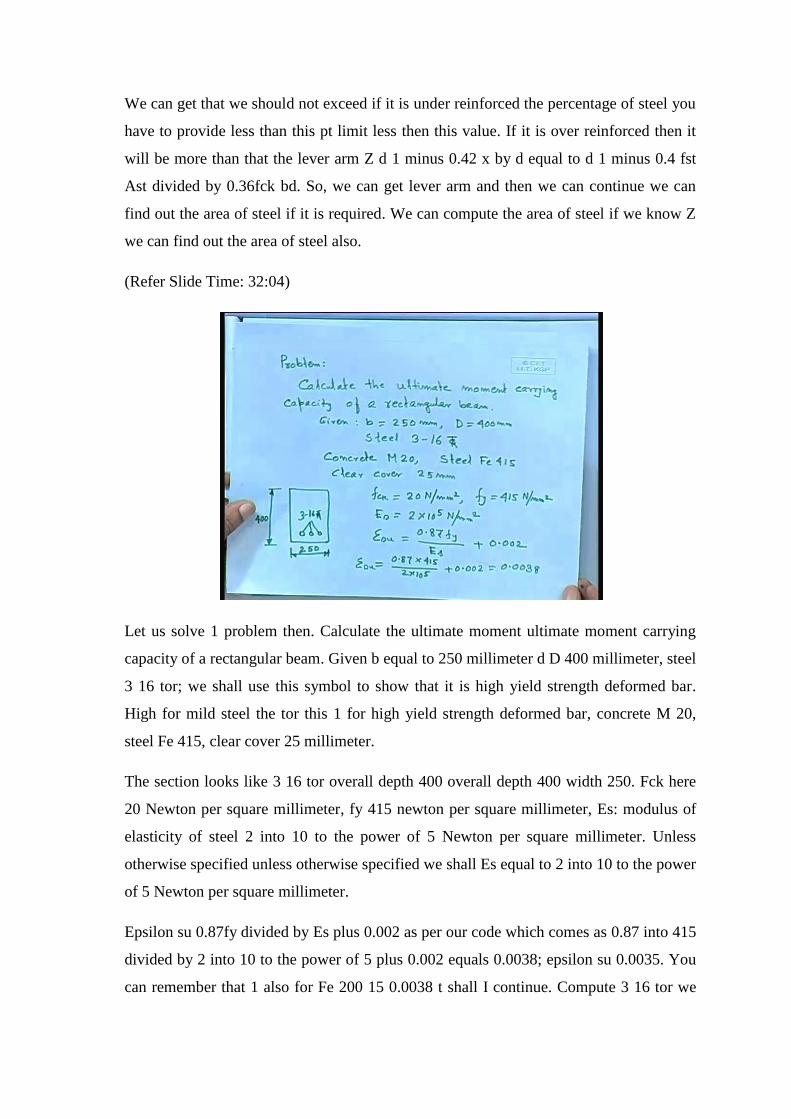
Let us solve 1 problem then. Calculate the ultimate moment ultimate moment carrying
capacity of a rectangular beam. Given b equal to 250 millimeter d D 400 millimeter, steel
3 16 tor; we shall use this symbol to show that it is high yield strength deformed bar.
High for mild steel the tor this 1 for high yield strength deformed bar, concrete M 20,
steel Fe 415, clear cover 25 millimeter.
The section looks like 3 16 tor overall depth 400 overall depth 400 width 250. Fck here
20 Newton per square millimeter, fy 415 newton per square millimeter, Es: modulus of
elasticity of steel 2 into 10 to the power of 5 Newton per square millimeter. Unless
otherwise specified unless otherwise specified we shall Es equal to 2 into 10 to the power
of 5 Newton per square millimeter.
Epsilon su 0.87fy divided by Es plus 0.002 as per our code which comes as 0.87 into 415
divided by 2 into 10 to the power of 5 plus 0.002 equals 0.0038; epsilon su 0.0035. You
can remember that 1 also for Fe 200 15 0.0038 t shall I continue. Compute 3 16 tor we
call it tor. So, we are writing t o r we call it tor steel we can say. The other 1 we say phi
whenever, we say phi sixteen phi; that means, it is mild steel if we specify this symbol
then we shall assume if the grade of steel is not given we shall assume that is Fe 415 at
least.
(Refer Slide Time: 36:47)
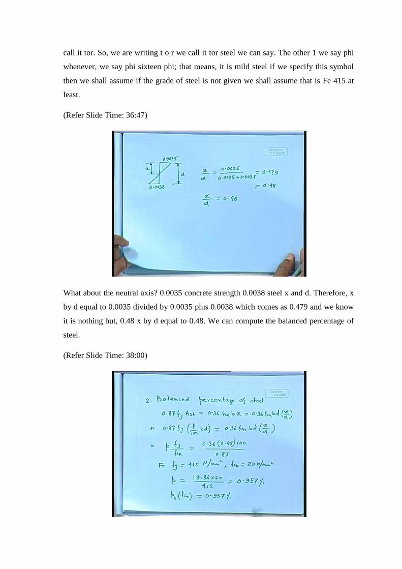
What about the neutral axis? 0.0035 concrete strength 0.0038 steel x and d. Therefore, x
by d equal to 0.0035 divided by 0.0035 plus 0.0038 which comes as 0.479 and we know
it is nothing but, 0.48 x by d equal to 0.48. We can compute the balanced percentage of
steel.
(Refer Slide Time: 38:00)

Balanced percentage of steel as it this is number 2. Let us write down the expression at
least in 1 case where from we are getting 0.87fy equal to 0.36fck b times x equal to
0.36fck bd multiplied by x by d. We can further we can write down 0.87fy p by 100 bd
equal to we are taking here percentage of steel 0.36fck bd times x by d. Or p fy by fck
equal to 0.36 0.48 times 100 divided by 0.87 0.36 bd bd cancelled x by d is nothing, 0.48
times 100 divided by 0.87.
For fy equal to 415 newton per square millimeter that is the grade specified in this
problem fcx equal to 20 Newton per square millimeter which we have to take in this
problem. P comes as computing all those things equal to 0.957 percent. That balanced
percentage of steel 0.957 percent we can write down since, we have specified areas pt
lim; limiting value we can say pt lim equal to 0.957 percent. That balanced percentage of
steel limiting value.
(Refer Slide Time: 41:04)
Area of steel provided 3 16 tor 603 square millimeter. Percentage of steel equal to 603
multiplied by 100 divided by 250 into what is the effective depth; so far we have not
come across that. Let us find out the effective depth effective depth equal to 400 minus
clear cover 25 minus 16 by 2 comes as 367.
So, 250 is the width of the beam multiplied by 367 equal to 0.657 percent less than the
limiting value 0.957 percent. Hence, the beam is under reinforced hence the beam is
under reinforced.

(Refer Slide Time: 43:04)
We can compute, Mu due to steel failure Mu equal to 0.87fy multiplied by p by 100 the
expression we have already derived 1 minus p by 100 times fy by fcx times bd square. At
least once for all let us write down the full expression 0.657 is the percentage of steel we
have computed which is provided 3 16 bar 1 minus 0.657 by 100 415 by 20 times b is
how much 250 d is 367 equals 68987082 Newton millimeter or 68.98 kilo Newton
meter. Moment carrying capacity due to steel failure we shall get 68.98 kilo Newton
meter.
We can check whatever due to concrete failure we can take whatever due to concrete
failure.

(Refer Slide time: 45:03)
So, 5 Mu due to concrete failure, Mu equal to 0.36fck bd square x by d 1 minus 0.42 x
by d equals 0.36 250 367 0.48 1 minus which comes as 93.13 kilo Newton meter. This 1
in Newton millimeter and we are getting after the segregation that 93.13 kilo Newton
meter. Ultimate moment capacity Mu 68.98 kilo Newton meters due to steel failure. So,
the problem we have done in the very beginning that is you’re that with took this
problem b, any way we took this problem anyway we can write down there is nothing
wrong in it.
(Refer Slide time: 47:48)

We have taken the problem to summarize the whole thing that 3 16 bars and effective
depth 367 when computed, Mu 20 Fe 415. We got Mu due to concrete failure equals
93.13 kilo Newton meter and Mu due to steel failure 68.98 kilo Newton meter. We have
taken the section the overall depth 400; we have taken the section and we have got these
2 values.
Our objective should be that, we have to provide the section that 93.13 kilo Newton
meter and the other case we are getting 68.98. Almost you can say 25 difference of 25
kilo newton meter; that means, we can add 1 more bar we can find out we can check we
can add 1 more bar and we can find out that, whether it is coming closer to 93.13 or the
other way also it may exceed also. In that case we have to choose that bar also that bar
that 16 that we can use to have whole numbers. So, that design is such that where the
design comes that we have to optimize this section.
The steel and concrete failure the moment capacity due to that steel failure and due to
concrete it should come closer. Otherwise, it is not an optimum design this 1 we have
done this particular problem we have done this problem we have taken it as a analysis
everything has given we are finding the moment carrying capacity.
The other alternative that what you have to do that we have to do the design. Therefore,
we have to do a lot of calculation if you do it with the calculator then you have to do lot
of calculation again you change the depth not the 1 process, not the single process that
you will go and solve it and you will get the required depth not like that. Maybe you
have to change the depth or maybe you have to change the bar diameter. So, the process
is a little bit you can say iterative and it comes in that fashion.
What we shall do in the next class we shall solve the problem; few more problem we
shall solve and there we shall do the design.

(Refer Slide time: 51:20)
We shall summarize our beam problem let us summarize it. We call it limit state of we
are considering only flexure only bending we are considering. So far, we have taken
singly reinforced section and rectangular singly reinforced section and rectangular.
It is possible this 1 slab, this is the part of the slab this is the rib or web of the beam. If
you take this part this is your slab, this is web we take it we can also take it as a T-beam
where we shall take the effect of the slab. Because, when we cast the slab and beam we
cast altogether in the same time we cast it we can consider this 1 as 1 unit. And when we
take this 1 unit our code says that how far you can go. That means, this is the beam
whether shall we take that or shall we take this portion only no, shall we take this portion
only the rectangle whatever you are considering. And we are not taking the effect of this
plane spot or the slab part.
We can go certain distance from both sides from the central line of the beam we can go
and we can take the flange width. When you are considering that when you taking that
part then we consider as a T-beam. Similarly, it is possible as say at the corner at the side
at the end the beam could be like this; that means, the slab ends and the beam either you
can take it as L-beam or inverted L-beam whatever you call; it can take this effect. This
is all related to your the singly reinforced section where, all the reinforcement in the
tensile side. It is also possible that we have to consider the other part that is called doubly
reinforced section.

(Refer Slide time: 54:03)
So, 1 part is the singly reinforced, so far whatever we are doing we have done so far the
rectangular 1 only. And the other 1 doubly reinforced section. In this case, we provide
reinforcement this is your tension side, compression side. What is the basic philosophy?
The basic philosophy is that, tension side you are providing the reinforcement. Concrete
can take compression at the top for this usual case we are talking concrete can take
compression at the top. And from the equilibrium consideration we can provide that your
say equivalent your tension reinforcement. So, that it will be in equilibrium and we can
calculate the moment carrying capacity.
Sometimes it may happen due to some problem that we cannot increase the depth; the
moment is such that we cannot increase the depth. The moment has come due to
computation due to your load external load we have got whatever moment we have got
it. But we cannot increase the moment of resistance. That means, we cannot increase the
depth if it always preferable that increase the depth because, if you increase the depth
that is coming square this square whereas, if we increase the width then it is simply
multiplied by b only.
So, it is always preferable you increase the depth. So, that is why you always increase the
depth. If we increase the depth we can get that all section make it singly reinforced
section, but sometimes it happens that we cannot increase the depth. Therefore, what you
have to do the moment carrying capacity due to singly reinforced section we can get
certain say Mu 1 the moment is Mu that which you have to provide. Mu 1 we have got

from singly reinforced section the remaining balance Mu minus Mu 1, we shall provide
providing compression steel.
So, if you provide the steel in the compression side similarly, you have to provide for
equilibrium we have to provide in the tension side also we have to provide the
reinforcement. And then we shall get tension side that something this 1 for this say Ast 1
the remaining part say Ast 2. So, Ast 1 plus Ast 2 you have to provide in the tension side
so that we shall do it in 1 class that we shall do. So, this is the whole thing we shall do.
So, far the limit state of collapse taking flexure only. There are other part also that we
have to be taken care of CR also we have to be taken care of, when we shall design the
beam.
Thank you.