
Design of Light Rail Transit Complex...
18
Design of Light Rail Transit Overhead Contact Systems at Complex Intersections WILLARD D. WEISS AND JEAN-LUC DUPONT L t t rail transit (LRT) intersec- ns and turning movements in dOwntown areas present some unique and complex problems in over- head contact system (OCS) design. However, OCS design procedures and principles can be applied at such loca- tions to provide both economic con- struction and trouble-free vehicle op- eration. SPIDER has been developed as a software tool to facilitate OCS design at complex intersections The program is interactive and permits effi- cient and accurate design of compli- cated overhead guying networks. It performs the following analyses: layout of overhead hardware, calcula- tion of tensions in guying network, optimization of trolley wire profile, and determination of resultant pole loadings. Through the interactive process, the program allows the de- signer to optimize the overhead con- tact wire profile by adjusting guy wire tensions and attachment heights. Plan drawings can then be generated at any scale and transferred to a computer- assisted drafting (CAD) system for plotting final construction drawings. The SPIDER program, with its CAD interface, has been used extensively for OCS design on LRT projects in- cluding the Sacramento, Guadalupe, and Long Beach-Los Angeles LRTs, the Lowell Historic Trolley, and on several electric trolley coach projects in San Francisco and Seattle. The pro- gram has demonstrated economies in both the design and construction processes. Morrison-Knudsen Engineers, Inc., 180 Howard Street, San Francisco, Calif. 94105. 408
-
Upload
hoangnguyet -
Category
Documents
-
view
214 -
download
0
Transcript of Design of Light Rail Transit Complex...

Design of Light Rail Transit Overhead Contact Systems at
Complex Intersections
WILLARD D. WEISS AND JEAN-LUC DUPONT
Lt t rail transit (LRT) intersec- ns and turning movements in dOwntown areas present some
unique and complex problems in over-head contact system (OCS) design. However, OCS design procedures and principles can be applied at such loca-tions to provide both economic con-struction and trouble-free vehicle op-eration. SPIDER has been developed as a software tool to facilitate OCS design at complex intersections The program is interactive and permits effi-cient and accurate design of compli-cated overhead guying networks. It performs the following analyses: layout of overhead hardware, calcula-tion of tensions in guying network, optimization of trolley wire profile, and determination of resultant
pole loadings. Through the interactive process, the program allows the de-signer to optimize the overhead con-tact wire profile by adjusting guy wire tensions and attachment heights. Plan drawings can then be generated at any scale and transferred to a computer-assisted drafting (CAD) system for plotting final construction drawings. The SPIDER program, with its CAD interface, has been used extensively for OCS design on LRT projects in-cluding the Sacramento, Guadalupe, and Long Beach-Los Angeles LRTs, the Lowell Historic Trolley, and on several electric trolley coach projects in San Francisco and Seattle. The pro-gram has demonstrated economies in both the design and construction processes.
Morrison-Knudsen Engineers, Inc., 180 Howard Street, San Francisco, Calif. 94105.
408
System Design and Vehicle Performance 409
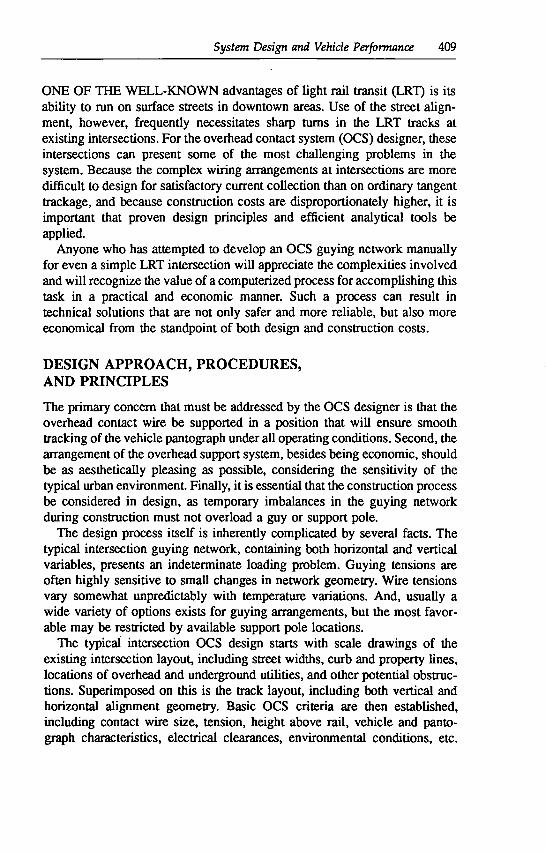
ONE OF THE WELL-KNOWN advantages of light rail transit (LRT) is its ability to run on surface streets in downtown areas. Use of the street align-ment, however, frequently necessitates sharp turns in the LRT tracks at existing intersections. For the overhead contact system (OCS) designer, these intersections can present some of the most challenging problems in the system. Because the complex wiring arrangements at intersections are more difficult to design for satisfactory current collection than on ordinary tangent trackage, and because construction costs are disproportionately higher, it is important that proven design principles and efficient analytical tools be applied.
Anyone who has attempted to develop an OCS guying network manually for even a simple LRT intersection will appreciate the complexities involved and will recognize the value of a computerized process for accomplishing this task in a practical and economic manner. Such a process can result in technical solutions that are not only safer and more reliable, but also more economical from the standpoint of both design and construction costs.
DESIGN APPROACH, PROCEDURES, AND PRINCIPLES
The primary concern that must be addressed by the OCS designer is that the overhead contact wire be supported in a position that will ensure smooth tracking of the vehicle pantograph under all operating conditions. Second, the arrangement of the overhead support system, besides being economic, should be as aesthetically pleasing as possible, considering the sensitivity of the typical urban environment. Finally, it is essential that the construction process be considered in design, as temporary imbalances in the guying network during construction must not overload a guy or support pole.
The design process itself is inherently complicated by several facts. The typical intersection guying network, containing both horizontal and vertical variables, presents an indeterminate loading problem. Guying tensions are often highly sensitive to small changes in network geometry. Wire tensions vary somewhat unpredictably with temperature variations. And, usually a wide variety of options exists for guying arrangements, but the most favor-able may be restricted by available support pole locations.
The typical intersection OCS design starts with scale drawings of the existing intersection layout, including street widths, curb and property lines, locations of overhead and underground utilities, and other potential obstruc-tions. Superimposed on this is the track layout, including both vertical and horizontal alignment geometry. Basic OCS criteria are then established, including contact wire size, tension, height above rail, vehicle and panto-graph characteristics, electrical clearances, environmental conditions, etc.

410 LIGHT RAIL TnNsn: NEW SYSTEM SUCCESSES
Once the basic criteria have been established, intersection OCS design may proceed. In developing the optimum design, three objectives should be met. First, the contact wire must be supported horizontally (registered) so that it remains on the pantograph collector strip at all times; consideration should be given to factors such as pantograph width, vehicle sway, track alignment, pole deflection, wind blow-off, and temperature variation. Second, the con-tact wire must be supported vertically at a constant height above the track to offer a smooth profile to the pantograph. The "stiffness" of the contact wire (resistance to uplift due to pantograph pressure) along the track should also be as uniform as possible to achieve "sparkless" commutation between the pantograph and the contact wire. In addition, at turnouts any converging wire must remain sufficiently high above the horns of the pantograph to prevent hooking of the converging wire under the pantograph horn. Third, guying tensions and pole loadings should be kept to a minimum. The guying network should be kept as simple as possible, to minimize the structural support requirements and resulting costs, as well as visual obtrusion.
With these objectives in mind, the design process itself typically consists of the following steps:
Pole locations—Selection of locations of support poles at the sides of the streets;
Guying network—Development of a network of guy wires to register and support the contact wire;
Tension calculations—Calculation of guy wire tensions and attachment heights; and
Pole loadings—Calculation of loads in support poles.
Within the framework of this design process, the OCS designer should keep in mind a number of important principles to develop an overhead wiring installation that performs satisfactorily and is economical, safe, and aesthet-ically pleasing. Some of these princi1es are discussed below, along with descriptions of the individual steps involved. For further clarity, these steps are illustrated in Figures 1 through 3, using the example of a single track turning movement at a typical street intersection.
Step 1—Pole Locations
To the extent possible, the poles are located by the designer so as to best accommodate the planned guying network layout. The pole locations, however, are often restricted by the physical conditions encountered at the intersection and by architectural requirements, which are not usually under the control of the OCS designer. Restrictions that apply to pole locations at

System Design and Vehicle Performance 411
intersections are similar to those at any location in city streets: offset from pole to curb; clearance to driveways, trees, and fire hydrants; and require-ments for joint-use with street lighting or traffic signal equipment.
Building eyebolts may also be available to support the OCS, but at intersections their use presents a minor drawback: their position is fixed, so once installed, there is no opportunity for vertical adjustment to improve the contact wire profile, as there is with a clamp on a pole. -
The selected pole locations for the example intersection with the given track alignment are shown in Figure 1.
Step 2—Guying Network
In the next step, the designer examines the layout of the intersection and looks for direct pole-to-pole cross-spans that are as close as possible to perpendicular to the track alignment (say within ±50). These cross-spans or "direct guys" form the starting point of the layout (see Figure 1). The designer then locates additional "semidirect" guys, which are perpendicular to the track but connected to only one pole. Next, the designer determines the position of the remaining registration points by dividing the spaces available between direct and semidirect registration points into equal segments that satisfy the maximum deviation criterion. The maximum deviation at each point is limited by the allowable radial load in the contact wire clamps used (see discussion on hardware below).
The layout of the guying network is completed with either "constant length pull-offs" or "variable length pull-offs." The constant length pull-off method uses identical steady arms at each registration point, and a "brail" wire, which parallels the contact wire throughout the curve, as shown in Figure 2. The variable length pull-offs are short cross-spans between bull rings, linked together and to the poles by a "backbone" wire (see Figure 3).
Several additional considerations must be taken into account when the guying network is laid out. Some of these are discussed below.
Hardware
Before establishing the guying network, the designer must have an under-standing of the available support hardware. Overhead hardware varies from manufacturer to manufacturer, in addition, a given manufacturer may have several types of hardware available depending upon the guying concepts to be employed. Figure 4 shows several types of support and registration assemblies. These vary not only in loading capacities but also in weight and apparent "hardness," which is an important consideration in achieving good commutation of the pantograph on the contact wire.

FIGURE 1 Intersection guying layout procedures, showing pole locations, direct and sernidirect guy wires, and registration points.
23- 0 I CLAW HEIGHTS
/ - -
POLES
WIRE
ADDITIONAL G&MING CSTANT THE INSIDE OF RVE \ON LENGTH
BRAIL _
PIJLLOFFS / - -,
CONTACT WIRE
FIGURE 2 Typical guying network using constant length pull-offs.

System Design and Vehide Performance 413
FIGURE 3 Typical guying network using variable length pull-offs.
Typically on new LRT projects, the hardware supplier is not known at the time that the design is prepared, and "generic" or "neutral" designs are required to permit competitive bidding. For extensions or rehabilitations of existing LRT systems, it may be possible to call out the hardware of the specific manufacturer that supplied the original equipment.
Generic designs may not fully utilize the capabilities of the hardware and may necessitate adjustments after the supplier is selected. For example, the designer may have assumed that the maximum allowable radial load in a pull-off is 500 lb. Thus, for a contact wire tension of 3,000 lb. 10 pull-offs would be required in a typical 90° turn. However, the actual hardware finally supplied may be able to sustain a 700-lb radial load; with such hardware, only 7 pull-offs would be needed on the 90° turn, resulting in a much simpler guying network.
This example highlights the importance of being familiar with the avail-able hardware. Coordination between the designer and the various manufac-turers before bidding is essential to ensure that the layout specified not only is feasible to all manufacturers, but also uses the available components as

414 LIGHT RAIL TRi'srr: NEW SYSTEM SUCCESSES
CURVE HANGER
PULL-OFF ARM
/7 -4TK SOLID BAR
TWIN PULL-OFF ARMS
PULL-OFF ARM WITH INSIDE GUY DUMMY MESSENGER
FIGURE 4 Typical contact wire support and registration hardware.
closely as possible to their rated limits. In addition, the design should be reviewed and finalized with the selected manufacturer after bidding.
Inside Guying
A second consideration concerns the proper use of inside guy wires. Using either the constant length or the variable length pull-off method, the guying network on the inside of the curve (dashed lines, Figures 2 and 3) is not needed for horizontal registration. However, inside guy wires are needed to assist in supporting the weight of the equipment. This is particularly impor-tant when more than one track is to be wired, or when additional hardware is to be supported (section insulators, contactors for traffic signal control, etc.). Furthermore, inside guy wires are needed so that most of the guying network can be installed prior to contact wire stringing.
System Design and Vehicle Performance 415
Inside guy wires cause the inside and outside poles to pull against each other, thereby increasing pole loading; therefore the number of wires should be kept to a minimum. As a general rule, there should be at least one inside guy wire at every second or third registration point.
Reduced Contact Wire Tension
To limit the radial loads in pull-offs, it is sometimes desirable to reduce the normal contact wire tension in intersections, for example, from 2,500 lb to 1,500 lb. This permits a smaller number of pull-offs in the curve and therefore a simpler guying network and reduced pole loadings.
Tension reduction, however, should be applied selectively, for two reasons. First, the decreased tension in the contact wires makes it more difficult to develop a uniform profile, and the resulting decreased tension in outside guy wires diminishes their capability to provide vertical support to the equipment without raising the clamp heights. Second, the guys used as tension reducers themselves add to the complexity of the installation, both structurally and aesthetically, which may offset the positive effect obtained from the reduced number of pull-offs. Nevertheless, this technique can often result in an improved guying network, provided the reduction in tension is carefully selected.
Wire Crossings and Turnouts
At crossings and turnouts, the two joining contact wires should be installed so as to maintain essenually the same elevation to avoid hooking of the panto-graph over the incoming wire. The wires must be held firmly in position by the guying network, despite the pantograph push-up force, which may be acting on only one of the two wires. To achieve this, a support point common to both contact wires should be located approximately 10 to 20 ft from each crossing point, the distance depending on the angle of the turnout used.
At contact wire crossings, special attention must be given to the selection of appropriate hardware. At angles below 30°, a contact wire bridge with common supports at approximately 4 ft on either side is satisfactory. For crossing angles between 30° and 90°, it is usually necessary to install supplemental parallel runners to make sure that the pantograph does not hook the crossing contact wire.
Step 3—Tension Calculations
Upon completion of the conceptual wiring layout, the designer determines the guy wire tensions. All guy wire tension calculations are performed for the

416 Lici-rr RAIL TRANsrn NEW SYsTEM SUCCESSES
conductor's reference temperature, usually 60°F. The tensions on inside guy wires are selected first; they are normally kept to a nominal value of a few hundred pounds. The tensions on the outside guy wires are then derived from the geometry of the network by summation of forces at each node point.
The attachment heights of the guy wires on the poles, or "clamp heights," are then calculated considering the vertical load-to-tension ratios and the distances to the poles. Some adjustments in previously determined tensions may be necessary at this time to stay within reasonable limits for pole attachment heights. Guy wires are grouped as much as is feasible to limit the number of pole bands.
The entire process of calculating tensions and clamp heights lends itself readily to an interactive computer process discussed in detail later.
Step 4—Pole Loadings
Resultant horizontal loads and bending moments on poles are calculated by vectorial summation of individual loads and moments. Poles can then be designed, or selected from a set of standard poles, for the resulting bending moments and deflecting loads. Pole selection must take into account not only provision of adequate bending moment capacity, but also restriction of lateral deflection to within allowable limits.
Unbalanced Pole Loading
Care must be exercised in the pole selection process for several reasons. First, in complex intersections, poles are often loaded from opposing directions and the recalculated resultant bending moment cOmbining all guy wires can be, in some instances, less than the individual bending moments, or less than the partial geometric sum of individual bending moments. In selecting the pole size, any guy wire that "helps" the pole should be removed and the resulting bending moment calculated, to establish the potential worst-case loading condition.
Construction loads must also be considered. For example, poles at the entrance to an intersection are often selected to be temporary dead ends and may be subjected to additional loads during the construction period. One such condition occurs when prestressing is required to eliminate initial stretch and long-term creep.
Temperature Variations
As mentioned under Step 3, all guy wire tensions and attachment heights are calculated based on the "reference temperature." In an intersection wiring

System Design and Vehicle Performance 417
network, guy wire tensions and resultant pole loadings at other temperatures are very difficult to predict accurately. General purpose structural engineering computer programs, such as ANSYS or ABAQUS, have the required Ca-pability to model both cable and beam elements to simulate the overall intersection, including all wires and poles under temperature and/or ice or wind loading. However, such programs are relatively expensive to use, in terms of both labor to prepare the data and actual processing time.
An approximate approach to calculating the maximum loading on the pole is to assume that the bending moment on the pole varies in proportion to the contact wire tension. If the tension of the contact wires varies from, for example, 3,000 lb at 60°F to 4,000 lb at 25°F, the bending moment on the pole is assumed to increase by 4,000/3,000 = 1.33. For poles located on the outside of the curve, this assumption is usually conservative.
However, this approximation cannot necessarily be applied to poles on the inside of the curve. Because of the general elasticity of the guying network and of the differential stiffness between heavily loaded, strong outside poles and lightly loaded, weaker inside poles, the bending moment on the inside poles may actually be larger at high temperature (low contact wire tension) than at low temperature (high contact wire tension).
The amount by which the bending moment on the inside poles increases depends on many factors and is difficult to estimate. Calculations have shown that, in typical intersections, the maximum bending moment at high tempera-ture can be anywhere from 1.2 to 2 times the bending moment at the reference temperature. One way to reduce the impact of the phenomenon is to increase the tension on the inside guy wires and to increase the stiffness of the inside poles. As a general rule, the strength (maximum allowable bending moment and resistance to deflection) of the poles selected for the inside of the curve should not be less than one-third to one-half of the strength of outside poles.
COMPUTERIZED DESIGN PROCESS
The OCS intersection design process described above was illustrated for a single-track turning movement. Intersections with multiple tracks, turnings, and crossings involve the same principles, but are more complicated, of course, because of the additional contact wires and guy wires in the network. Moreover, the design process nearly always requires a certain amount of iteration, as the initial layout concept may result in poorly balanced pole or guy loading, initial pole locations may not be suitable, or various other conflicts may develop. Because the tension and clamp height calculations are usually time-consuming, a computerized approach is of considerable benefit

418 LIGHT RAIl. TRANsrr NEW SYSTEM SUCCESSES
and can result in appreciable cost savings in performing the inevitable iterations required in the design process.
To facilitate the OCS design at intersections, Morrison Knudsen Engineers, Inc., developed a computer program called Special Intersection Design Pro-gram, or SPIDER. SPIDER is an interactive computer program that enables the designer to create a model of the intersection on a video graphic display, analyze the loading, and optimize the design in an efficient and accurate manner.
The Model
SPIDER represents the overhead contact system network by a model consist-ing of nodes and connections. Nodes are used to represent poles, bull rings, overhead hardware, and general purpose markers. A node is described by its coordinates (x,y,z), a type description (e.g., pole, bull ring, contact wire connection, etc.), and a mass. Connections are used to represent contact wires, guy wires, hardware elements, or boundary lines. A connection is described by its end-point nodes, a type description (e.g., 300 kcmil contact wire, /s in. guy wire, property line, etc.), its tension, and the clamp height for a wire attached to a pole.
The system developed to date accommodates up to 500 nodes and 600 connections. These numbers are sufficient even for the most complicated LRT intersections. Large yards may be separated into two or more indepen-dent networks, if necessary.
Operation of the SPIDER program generally proceeds in two phases: development of the horizontal layout, and establishment of the vertical profile.
Horizontal Layout
As the coordinates (x,y) of the nodes are entered by the designer, the data are continuously displayed graphically on the screen for easy checking and referencing. When a connection or wire is entered, the tension is specified by the designer for contact wires and redundant guy wires; the tension is left blank for other guy wires. The program then calculates the missing tensions, balancing the loads vectorially at each node.
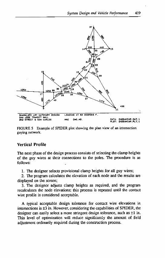
The process of entering data and balancing nodes is continued until all nodes are satisfactorily balanced in the (x,y)-plane. An example of the completed plan view at this point is shown in Figure 5. The contact wire is now registered properly, and the design focuses on the second principal objective, which is to provide a smooth vertical profile.
System Design and Vehicle Performance 419
036
GUADALUPE LRT CAIENARY DESIGN LOADING AT 60 DEGREES F. SAN JOSE TRANSIT HALL 2ND STREET S SAN CARLOS MKE DWG.NO . DATA: 2NDSANCAR.OAT: I
PLOT: 2NOSANCAR . PLT: I
FIGURE 5 Example of SPIDER plot showing the plan view of an intersection guying network.
Vertical Profile
The next phase of the design process consists of selecting the clamp heights of the guy wires at their connections to the poles. The procedure is as follows:
The designer selects provisional clamp heights for all guy wires; The program calculates the elevation of each node and the results are
displayed on the screen; The designer adjusts clamp heights as required, and the program
recalculates the node elevations; this process is repeated until the contact wire profile is considered acceptable.
A typical acceptable design tolerance for contact wire elevations in intersections is ±3 in. However, considering the capabilities of SPIDER, the designer can easily select a more stringent design tolerance, such as ±1 in. This level of optimization will reduce significantly the amount of field adjustment ordinarily required during the construction process.

VERTtCAL PROFILL
I-
w 21.0
z 20.75 0 I-
20.5 w -J 17 39 16 19 20 21 22 23 24 25 37
1-IORIZONTAL SCALE
0 20 40 rEEr
I I I
GUADALUPE LRT CATENARY DESIGN LOADING AT 60 DEGREES V. SAN JOSE TRANSIT MALL 2ND STREET & SAN CARLOS
DATA: 2NDSANCAR.: 1 PLOT: 2NDSANCAR.PLT: 2
FIGURE 6 Example of SPIDER plot showing the plan view of an intersection guying network.

System Design and Vehicle Performance 421
At this stage of the design, a plot of the contact wire profile can be produced, which will demonstrate the smoothness of the wire; any irreg-ularities in the profile are highlighted and can be easily corrected by adjusting the appropriate clamp heights or guy wire tensions. Figure 6 shows an example of a contact wire profile plot.
In the above design process, the horizontal wiring layout and vertical profiling can be easily adjusted or modified through a simple iterative process to arrive at the most economical combination of guying, support poles, and hardware.
Design Documents
The various SPIDER outputs can be used as design records; they include:
Electronic data file saved on disk or tape; Plots of plan view, showing node numbers, tensions and lengths of
wires; Plots of contact wire profile; and Printouts, including node table (see Figure 7), wire table (see Figure 7),
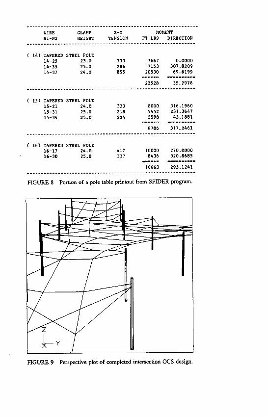
and pole table (see Figure 8).
In addition, the electronic file can be transferred to a computer-assisted drafting (CAD) system to prepare a formal drawing. In the CAD operation, street backgrounds, construction notes, title block, etc., are added and a final drawing is plotted with ink on Mylar.
A supplement to the SPIDER program permits the designer to plot a perspective view of the completed intersection OCS from any desired direc-tion, above or below the contact wire level. These plots are useful in visualizing the aesthetics of a chosen layout. An example of a perspective plot produced on a recent project is shown in Figure 9.
EXAMPLES OF SPIDER DESIGNS
The SPIDER program, with its CAD interface, has been used successfully to design the OCS for several rail transit projects in recent years. Among these are the Sacramento, Guadalupe Corridor, and Long Beach-Los Angeles LRT schemes, and the Lowell historic trolley reconstruction project. Together these projects have involved over 30 intersection designs. Figure 10 shows one of the completed OCS installations on the Guadalupe Corridor Project, the First Street and Younger Avenue intersection in downtown San Jose.
In addition to LRT applications, the SPIDER program has been used extensively for design of two-wire trolley overhead for electric trolley

NODAL INFORJ4ATION ----NODE---- BASELINE COORDINATES LOCAL NUN NTY TYPE --X-- --Y-- --1-- ELEVATION WEIGHT
1 800 END -224.0 0.668 0.0 0.0 0.0 8 800 END -13.382 262.515 0.0 0.0 0.0 9 700 POLST -129.0 -40.0 0.0 0.0 0.0 11 700 POLST 42.0 -43.0 0.0 0.0 0.0 13 700 POLST 28.20 98.0 0.0 0.0 0.0 14 700 POLST -28.20 98.0 0.0 0.0 0.0 15 700 POLST -43.50 39.0 0.0 0.0 0.0 16 700 POLST -129.0 40.0 0.0 0.0 0.0 17 20 SPAN -129.0 -5.0 20.897 20.897 10.0 18 20 SPAN -85.783 -3.032 20.926 20.926 10.0 19 20 SPAN -65.884 3.820 20.794 20.794 10.0 20 20 SPAN -47.845 14.659 20.683 20.683 10.0 21 20 SPAN -32.742 28.682 20.942 20.942 10.0 22 20 SPAN -21.780 43.811 20.667 20.667 10.0 23 20 SPAN -13.772 60.790 20.742 20.742 10.0 24 20 SPAN -9.049 79.007 20.938 20.938 10.0 25 20 SPAN -8.0 98.0 20.921 20.921 10.0 26 10 RING -84.638 -7.899 21.851 21.851 5.0 27 10 RING -24.709 -16.114 23.492 23.492 5.0 28 10 RING 0.172 -------------------------------------------------------------------------
30.836 22.292 22.292 5.0
WIRE INFORMATION ENDPOINT NODES WIRE X-Y 2 WIRE CLAMP PLAN
N1-N2 TYP1-TYP2 TYPE TENSION TENSION LENGTH HEIGHT ANGLE
1-9 END-POLST CW300 1250 0.0 103.339 25.0 336.8250 1-17 END-SPAN GUY3/8 1250 8.5 95.171 20.750 356.5856 8-37 END-SPAN GUY3/8 2500 11.3 114.604 20.750 271.8736 9-17 POLST-SPAN GUY3/8 462 -34.4 35.097 24.0 90.0000 9-40 POLST-RING GUY3/8 1174 -78.1 32.204 25.0 39.5657 11-21 POLST-SPAN GUY3/8 577 -25.4 103.660 26.0 136.1972 11-27 POLST-RING GUY3/8 1469 -92.1 72.064 28.0 158.0485 11-28 POLST-RING GUY3/8 804 -54.0 85.052 28.0 119.5315 13-25 POLST-SPAN GUY3/8 443 -31.6 36.292 24.0 180.0000 13-29 POLST-RING GUY3/8 730 -44.7 37.186 24.0 212.4515 13-37 POLST-SPAN GUY3/8 561 -24.4 62.739 24.0 127.1297 14-25 POLST-SPAN GUY3/8 333 -26.1 20.262 23.0 0.0000 14-35 POLST-RING GUY3/8 286 -37.7 23.359 25.0 307.8209 14-37 POLST-SPAN GUY3/8 855 -43.8 53.380 24.0 69.6199 15-21 POLST-SPAN GUY3/8 333 -57.2 15.124 24.0 316.1960 15-31 POLST-RING GUY3/8 218 -19.6 39.394 25.0 231.3647 15-34 POLST-RING GUY3/8 224 -21.6 34.483 25.0 43.1881 16-17 POLST-SPAN GUY3/8 417 -24.1 45.075 24.0 270.0000 16-30 POLST-RING GUY3/8 337 -21.9 52.872 25.0 320.8685 17-39 SPAN-SPAN CW300 1250 -1.3 24.025 358.6811 18-19 SPAN-SPAN CW300 1250 -7.8 21.046 19.0006 18-26 SPAN-RING GUY3/8 487 41.4 5.018 283.2424 18-30 SPAN-RING GUY3/8 236 3.6 10.001 103.2397 18-39 SPAN-SPAN CW300 1250 -3.5 19.363 187.4810
FIGURE 7 Portion of a node table printout (top) and wire table printout (bottom) from the SPIDER program.
WIRE CLAKP -------------------------------------------------------------
X-Y MOMENT N1-N2 HEIGHT
------------------------------------------------------------ TENSION FT-LBS DIRECTION
TAPERED STEEL POLE 14-25 23.0 333 7667 0.0000 14-35 25.0 286 7153 307.8209 14-37 24.0 855 20530 69.6199
------------------------------------------------------------ 23528 35.2976
TAPERED STEEL POLE 15-21 24.0 333 8000 316.1960 15-31 25.0 218 5452 231.3647 15-34 25.0 224 5598 43.1881
------------------------------------------------------------ 8786 317.2461
TAPERED STEEL POLE 16-17 24.0 417 10000 270.0000 16-30 25.0 337 8436 320.8685
------------------------------------------------------------ 16663 293.1241
FIGURE 8 Portion of a pole table printout from SPIDER program.
FIGURE 9 Perspective plot of completed intersection OCS design.

424 LIGHT RAIL TNsrn NEW SYSTEM SUCCESSES
H - /
FIGURE 10 The completed intersection at First Street and Younger Avenue in San Jose, designed using the SPIDER program.
coaches in San Francisco and Seattle. In these two Cities alone, the program has been used for the design of guying networks for more than 100 intersec-lions. Similarly, it has been applied in the design of OCS in highly complex areas such as maintenance and storage yards, where multiple tracks intersect and numerous turning movements are required. In most of these applications, final construction drawings were produced directly from the SPIDER output using its CAD interface capability.
CONCLUSIONS
Because of the complexity of the typical intersection overhead contact wiring network, the design principles outlined in this paper should be Carefully applied to produce an economical, aesthetically pleasing, and trouble-free facility. The SPIDER program greatly aids in the design process, and the versatility of this tool in the hands of experienced OCS designers has already proven its worth in numerous applications.
The design process itself, using the SPIDER program with its capability to examine numerous guying and support options, easily costs less than half that of the equivalent manual process. The real economics, however, lie in the resulting construction cost savings, through the ability to optimize the final configuration and minimize the number of poles, guys, and support hardware. Although it is difficult to quantify specific cost comparisons, considering that
System Design and Vehicle Performance 425
eliminating a single pole in a typical intersection can represent a 10 to 30 percent savings, the potential economies of the computerized approach are readily apparent.
Added to this, the inherent accuracy of the SPIDER design reduces the number of field adjustments that typically are needed when installing to a more approximate design. Finally, the efficient and clean design produced by SPIDER is less likely to get out of balance during operation and should therefore decrease overall maintenance requirements.
In summary, the use of the SPIDER program not only ensures maximum economy in OCS construction costs, but also permits a convenient appraisal of the aesthetic impacts of a proposed layout The program now represents an economical and efficient resource for rapid design of any complex OCS guying network, from simple turning movements to complex intersections and multiple-track vehicle storage and service facilities.