Design of High Performance Multiply-Accumulate Computation...
4
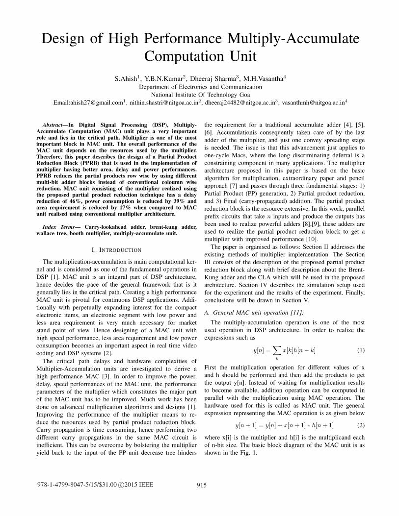
Design of High Performance Multiply-Accumulate Computation Unit S.Ahish 1 , Y.B.N.Kumar 2 , Dheeraj Sharma 3 , M.H.Vasantha 4 Department of Electronics and Communication National Institute Of Technology Goa Email:[email protected] 1 , [email protected] 2 , [email protected] 3 , [email protected] 4 Abstract—In Digital Signal Processing (DSP), Multiply- Accumulate Computation (MAC) unit plays a very important role and lies in the critical path. Multiplier is one of the most important block in MAC unit. The overall performance of the MAC unit depends on the resources used by the multiplier. Therefore, this paper describes the design of a Partial Product Reduction Block (PPRB) that is used in the implementation of multiplier having better area, delay and power performances. PPRB reduces the partial products row wise by using different multi-bit adder blocks instead of conventional coloumn wise reduction. MAC unit consisting of the multiplier realized using the proposed partial product reduction technique has a delay reduction of 46%, power consumption is reduced by 39% and area requirement is reduced by 17% when compared to MAC unit realised using conventional multiplier architecture. Index Terms— Carry-lookahead adder, brent-kung adder, wallace tree, booth multiplier, multiply-accumulate unit. I. I NTRODUCTION The multiplication-accumulation is main computational ker- nel and is considered as one of the fundamental operations in DSP [1]. MAC unit is an integral part of DSP architecture, hence decides the pace of the general framework that is it generally lies in the critical path. Creating a high performance MAC unit is pivotal for continuous DSP applications. Addi- tionally with perpetually expanding interest for the compact electronic items, an electronic segment with low power and less area requirement is very much necessary for market stand point of view. Hence designing of a MAC unit with high speed performance, less area requirement and low power consumption becomes an important aspect in real time video coding and DSP systems [2]. The critical path delays and hardware complexities of Multiplier-Accumulation units are investigated to derive a high performance MAC [3]. In order to improve the power, delay, speed performances of the MAC unit, the performance parameters of the multiplier which constitutes the major part of the MAC unit has to be improved. Much work has been done on advanced multiplication algorithms and designs [1]. Improving the performance of the multiplier means to re- duce the resources used by partial product reduction block. Carry propagation is time consuming, hence performing two different carry propagations in the same MAC circuit is inefficient. This can be overcome by bolstering the multiplier yield back to the input of the PP unit decrease tree hinders the requirement for a traditional accumulate adder [4], [5], [6]. Accumulationis consequently taken care of by the last adder of the multiplier, and just one convey spreading stage is needed. The issue is that this advancement just applies to one-cycle Macs, where the long discriminating deferral is a constraining component in many applications. The multiplier architecture proposed in this paper is based on the basic algorithm for multiplication, extraordinary paper and pencil approach [7] and passes through three fundamental stages: 1) Partial Product (PP) generation, 2) Partial product reduction, and 3) Final (carry-propagated) addition. The partial product reduction block is the resource extensive. In this work, parallel prefix circuits that take n inputs and produce the outputs has been used to realize powerful adders [8],[9], these adders are used to realize the partial product reduction block to get a multiplier with improved performance [10]. The paper is organised as follows: Section II addresses the existing methods of multiplier implementation. The Section III consists of the description of the proposed partial product reduction block along with brief description about the Brent- Kung adder and the CLA which will be used in the proposed architecture. Section IV describes the simulation setup used for the experiment and the results of the experiment. Finally, conclusions will be drawn in Section V. A. General MAC unit operation [11]: The multiply-accumulation operation is one of the most used operation in DSP architecture. In order to realize the expressions such as y[n]= k x[k]h[n − k] (1) First the multiplication operation for different values of x and h should be performed and then add the products to get the output y[n]. Instead of waiting for multiplication results to become available, addition operation can be computed in parallel with the multiplication using MAC operation. The hardware used for this is called as MAC unit. The general expression representing the MAC operation is as given below y[n + 1] = y[n]+ x[n + 1] ∗ h[n + 1] (2) where x[i] is the multiplier and h[i] is the multiplicand each of n-bit size. The basic block diagram of the MAC unit is as shown in the Fig. 1. 915 978-1-4799-8047-5/15/$31.00 c 2015 IEEE
Transcript of Design of High Performance Multiply-Accumulate Computation...
Design of High Performance Multiply-AccumulateComputation Unit
S.Ahish1, Y.B.N.Kumar2, Dheeraj Sharma3, M.H.Vasantha4
Department of Electronics and Communication
National Institute Of Technology Goa
Email:[email protected], [email protected], [email protected], [email protected]
Abstract—In Digital Signal Processing (DSP), Multiply-Accumulate Computation (MAC) unit plays a very importantrole and lies in the critical path. Multiplier is one of the mostimportant block in MAC unit. The overall performance of theMAC unit depends on the resources used by the multiplier.Therefore, this paper describes the design of a Partial ProductReduction Block (PPRB) that is used in the implementation ofmultiplier having better area, delay and power performances.PPRB reduces the partial products row wise by using differentmulti-bit adder blocks instead of conventional coloumn wisereduction. MAC unit consisting of the multiplier realized usingthe proposed partial product reduction technique has a delayreduction of 46%, power consumption is reduced by 39% andarea requirement is reduced by 17% when compared to MACunit realised using conventional multiplier architecture.
Index Terms— Carry-lookahead adder, brent-kung adder,wallace tree, booth multiplier, multiply-accumulate unit.
I. INTRODUCTION
The multiplication-accumulation is main computational ker-
nel and is considered as one of the fundamental operations in
DSP [1]. MAC unit is an integral part of DSP architecture,
hence decides the pace of the general framework that is it
generally lies in the critical path. Creating a high performance
MAC unit is pivotal for continuous DSP applications. Addi-
tionally with perpetually expanding interest for the compact
electronic items, an electronic segment with low power and
less area requirement is very much necessary for market
stand point of view. Hence designing of a MAC unit with
high speed performance, less area requirement and low power
consumption becomes an important aspect in real time video
coding and DSP systems [2].
The critical path delays and hardware complexities of
Multiplier-Accumulation units are investigated to derive a
high performance MAC [3]. In order to improve the power,
delay, speed performances of the MAC unit, the performance
parameters of the multiplier which constitutes the major part
of the MAC unit has to be improved. Much work has been
done on advanced multiplication algorithms and designs [1].
Improving the performance of the multiplier means to re-
duce the resources used by partial product reduction block.
Carry propagation is time consuming, hence performing two
different carry propagations in the same MAC circuit is
inefficient. This can be overcome by bolstering the multiplier
yield back to the input of the PP unit decrease tree hinders
the requirement for a traditional accumulate adder [4], [5],
[6]. Accumulationis consequently taken care of by the last
adder of the multiplier, and just one convey spreading stage
is needed. The issue is that this advancement just applies to
one-cycle Macs, where the long discriminating deferral is a
constraining component in many applications. The multiplier
architecture proposed in this paper is based on the basic
algorithm for multiplication, extraordinary paper and pencil
approach [7] and passes through three fundamental stages: 1)
Partial Product (PP) generation, 2) Partial product reduction,
and 3) Final (carry-propagated) addition. The partial product
reduction block is the resource extensive. In this work, parallel
prefix circuits that take n inputs and produce the outputs has
been used to realize powerful adders [8],[9], these adders are
used to realize the partial product reduction block to get a
multiplier with improved performance [10].
The paper is organised as follows: Section II addresses the
existing methods of multiplier implementation. The Section
III consists of the description of the proposed partial product
reduction block along with brief description about the Brent-
Kung adder and the CLA which will be used in the proposed
architecture. Section IV describes the simulation setup used
for the experiment and the results of the experiment. Finally,
conclusions will be drawn in Section V.
A. General MAC unit operation [11]:
The multiply-accumulation operation is one of the most
used operation in DSP architecture. In order to realize the
expressions such as
y[n] =∑
k
x[k]h[n− k] (1)
First the multiplication operation for different values of x
and h should be performed and then add the products to get
the output y[n]. Instead of waiting for multiplication results
to become available, addition operation can be computed in
parallel with the multiplication using MAC operation. The
hardware used for this is called as MAC unit. The general
expression representing the MAC operation is as given below
y[n+ 1] = y[n] + x[n+ 1] ∗ h[n+ 1] (2)
where x[i] is the multiplier and h[i] is the multiplicand each
of n-bit size. The basic block diagram of the MAC unit is as
shown in the Fig. 1.
915978-1-4799-8047-5/15/$31.00 c©2015 IEEE
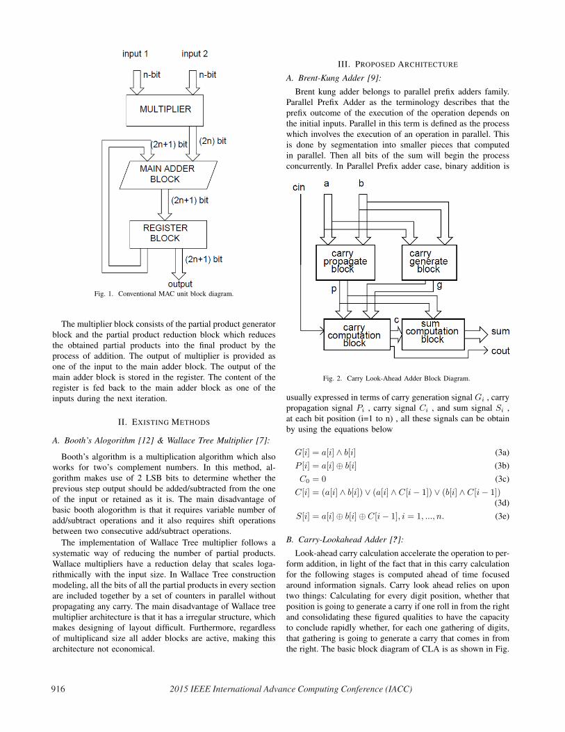
Fig. 1. Conventional MAC unit block diagram.
The multiplier block consists of the partial product generator
block and the partial product reduction block which reduces
the obtained partial products into the final product by the
process of addition. The output of multiplier is provided as
one of the input to the main adder block. The output of the
main adder block is stored in the register. The content of the
register is fed back to the main adder block as one of the
inputs during the next iteration.
II. EXISTING METHODS
A. Booth’s Alogorithm [12] & Wallace Tree Multiplier [7]:
Booth’s algorithm is a multiplication algorithm which also
works for two’s complement numbers. In this method, al-
gorithm makes use of 2 LSB bits to determine whether the
previous step output should be added/subtracted from the one
of the input or retained as it is. The main disadvantage of
basic booth alogorithm is that it requires variable number of
add/subtract operations and it also requires shift operations
between two consecutive add/subtract operations.
The implementation of Wallace Tree multiplier follows a
systematic way of reducing the number of partial products.
Wallace multipliers have a reduction delay that scales loga-
rithmically with the input size. In Wallace Tree construction
modeling, all the bits of all the partial products in every section
are included together by a set of counters in parallel without
propagating any carry. The main disadvantage of Wallace tree
multiplier architecture is that it has a irregular structure, which
makes designing of layout difficult. Furthermore, regardless
of multiplicand size all adder blocks are active, making this
architecture not economical.
III. PROPOSED ARCHITECTURE
A. Brent-Kung Adder [9]:
Brent kung adder belongs to parallel prefix adders family.
Parallel Prefix Adder as the terminology describes that the
prefix outcome of the execution of the operation depends on
the initial inputs. Parallel in this term is defined as the process
which involves the execution of an operation in parallel. This
is done by segmentation into smaller pieces that computed
in parallel. Then all bits of the sum will begin the process
concurrently. In Parallel Prefix adder case, binary addition is
Fig. 2. Carry Look-Ahead Adder Block Diagram.
usually expressed in terms of carry generation signal Gi , carry
propagation signal Pi , carry signal Ci , and sum signal Si ,
at each bit position (i=1 to n) , all these signals can be obtain
by using the equations below
G[i] = a[i] ∧ b[i] (3a)
P [i] = a[i]⊕ b[i] (3b)
C0 = 0 (3c)
C[i] = (a[i] ∧ b[i]) ∨ (a[i] ∧ C[i− 1]) ∨ (b[i] ∧ C[i− 1])(3d)
S[i] = a[i]⊕ b[i]⊕ C[i− 1], i = 1, ..., n. (3e)
B. Carry-Lookahead Adder [?]:
Look-ahead carry calculation accelerate the operation to per-
form addition, in light of the fact that in this carry calculation
for the following stages is computed ahead of time focused
around information signals. Carry look ahead relies on upon
two things: Calculating for every digit position, whether that
position is going to generate a carry if one roll in from the right
and consolidating these figured qualities to have the capacity
to conclude rapidly whether, for each one gathering of digits,
that gathering is going to generate a carry that comes in from
the right. The basic block diagram of CLA is as shown in Fig.
916 2015 IEEE International Advance Computing Conference (IACC)
a7 a6 a5 a4 a3 a2 a1 a0 × b7 b6 b5 b4 b3 b2 b1 b0
0 a7b0 a6b0 a5b0 a4b0 a3b0 a2b0 a1b0 a0b0a7b1 a6b1 a5b1 a4b1 a3b1 a2b1 a1b1 a0b1
0 a7b2 a6b2 a5b2 a4b2 a3b2 a2b2 a1b2 a0b2a7b3 a6b3 a5b3 a4b3 a3b3 a2b3 a1b3 a0b3
0 a7b4 a6b4 a5b4 a4b4 a3b4 a2b4 a1b4 a0b4a7b5 a6b5 a5b5 a4b5 a3b5 a2b5 a1b5 a0b5
0 a7b6 a6b6 a5b6 a4b6 a3b6 a2b6 a1b6 a0b6a7b7 a6b7 a5b7 a4b7 a3b7 a2b7 a1b7 a0b7
p15 p14 p13 p12 p11 p10 p9 p8 p7 p6 p5 p4 p3 p2 p1 p0
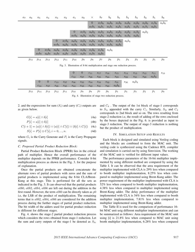
Fig. 3. Illustration of 8-bit multiplication and stage one reduction process.
0 0 c11 s17 s16 s15 s14 s13 s12 s11 s10c12 s27 s26 s25 s24 s23 s22 s21 s20 a0b2
0 0 c13 s37 s36 s35 s34 s33 s32 s31 s30 a0b4c14 s47 s46 s45 s44 s43 s42 s41 s40 a0b6
p15 p14 p13 p12 p11 p10 p9 p8 p7 p6 p5 p4 p3 p2 p1 p0
Fig. 4. Illustration of stage two reduction process.
2. and the expressions for sum (Si) and carry (Ci) outputs are
as given below.
G[i] = a[i] ∧ b[i] (4a)
P [i] = a[i]⊕ b[i] (4b)
C[i+ 1] = (a[i] ∧ b[i]) ∨ (a[i] ∧ C[i]) ∨ (b[i] ∧ C[i]) (4c)
S[i] = P [i]⊕ C[i], i = 0, ..., n. (4d)
where Gi is the Carry Generate and Pi is the Carry Propagate
signals.
C. Proposed Partial Product Reduction Block:
Partial Product Reduction Block (PPRB) lies in the critical
path of multiplier. Hence the overall performance of the
multiplier depends on the PPRB performance. Consider 8-bit
multiplication process as shown in the Fig. 3. for the purpose
of explanation.Once the partial products are obtained concatenate the
alternate rows of partial products with zeros and the sum of
partial products is implemented using the 8-bit CLA/Brent-
Kung at this stage. This is performed for all the sets as
indicated in the Fig. 3. It can observed that the partial products
a0b0, a0b2, a0b4, a0b6 are left out during the addition in the
first round. However, the term a0b0 can be directly taken as p0i.e, the LSB of the product of multiplication. The remaining
terms that is a0b2, a0b4, a0b6 are considered for the addition
process during the further stages of partial product reduction.
The bit width of the adders used for partial product reduction
is different for different stages.Fig. 4. shows the stage-2 partial product reduction process
which considers the rows obtained from stage-1 reduction. Let
the sum and carry outputs of the stage-1 be denoted as Ski
and Ck . The output of the 1st block of stage-1 corresponds
to S1i appended with the carry C1. Similarly, S2i and C2
corresponds to 2nd block and so on. The rows resulting from
stage-2 reduction i.e, the result of adding of the rows enclosed
by the boxes depicted in the Fig. 6. is provided as input to
stage-3 reduction. The output of stage-3 reduction is nothing
but the product of multiplication.
IV. SIMULATION SETUP AND RESULTS
Each block is designed and simulated using Verilog coding
and the blocks are combined to form the MAC unit. The
verilog code is synthesized using the Cadence RTL compiler
and simulation is carried out by using Simvision. The working
of the MAC unit is verified for different input values.
The performance parameters of the 16-bit multiplier imple-
mented by using different method are compared by using the
Table I. It can be observed that the area requirement of the
multiplier implemented with CLA is 29% less when compared
to booth multiplier implementation, 8.25% less when com-
pared to multiplier implemented using Brent-Kung adder. The
power requirement of the multiplier implemented with CLA is
52% less when compared to booth multiplier implementation,
4.38% less when compared to multiplier implemented using
Brent-Kung adder. The delay performance of the multiplier
implemented with CLA is 54% less when compared to booth
multiplier implementation, 7.81% less when compared to
multiplier implemented using Brent-Kung adder.
The Table II is used for the comparison of performance 16-
bit MAC unit usig different multiplier implementation and can
be summarized as follows: Area requirement of the MAC unit
using [i] is 21.8% less when compared to MAC unit using
booth multiplier implementation, 6.28% less when compared
2015 IEEE International Advance Computing Conference (IACC) 917
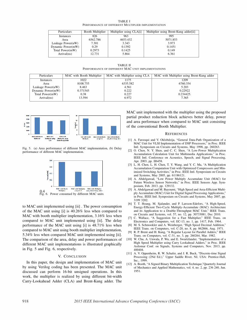
TABLE IPERFORMANCE OF DIFFERENT MULTIPLIER IMPLEMENTATION
Particulars Booth Multiplier Multiplier using CLA[i] Multiplier using Brent-Kung adder[ii]
Instances 826 963 995Area 6562.786 4653.432 5071.853
Leakage Power(uW) 7.301 3.343 3.973Dynamic Power(mW) 0.29 0.1392 0.1451
Total Power(mW) 0.2973 0.1425 0.149Arrival(ns) 12.731 5.864 6.361
TABLE IIPERFORMANCE OF DIFFERENT MAC UNIT IMPLEMENTATIONS
Particulars MAC with Booth Multiplier MAC with Multiplier using CLA MAC with Multiplier using Brent-Kung adder
Instances 1022 1175 1209Area 8108.755 6335.582 6760.354
Leakage Power(uW) 8.463 4.561 5.203Dynamic Power(mW) 0.371545 0.222 0.22922
Total Power(mW) 0.38 0.227 0.234425.Arrival(ns) 13.594 6.972 7.365
Fig. 5. (a) Area performance of different MAC implementation, (b) Delayperformance of different MAC implementation.
0.4Fig. 6. Power consumed by different MAC units
to MAC unit implemented using [ii] . The power consumption
of the MAC unit using [i] is 40.26% less when compared to
MAC with booth multiplier implementation, 3.16% less when
compared to MAC unit implemented using [ii]. The delay
performance of the MAC unit using [i] is 48.71% less when
compared to MAC unit using booth multiplier implementation,
5.34% less when compared MAC unit implemented using [ii].
The comparison of the area, delay and power performances of
different MAC unit implementations is illustrated graphically
in Fig. 5 and Fig. 6, respectively.
V. CONCLUSION
In this paper, the design and implementation of MAC unit
by using Verilog coding has been presented. The MAC unit
discussed can perform 16-bit unsigned operations. In this
work, the multiplier is realized by using different bit-width
Carry-Lookahead Adder (CLA) and Brent-Kung adder. The
MAC unit implemented with the multiplier using the proposed
partial product reduction block achieves better delay, power
and area performace when compared to MAC unit consisting
of the conventional Booth Multiplier.
REFERENCES
[1] A. Farooqui and V. Oklobdzija, “General Data-Path Organization of aMAC Unit for VLSI Implementation of DSP Processors,” in Proc. IEEEIntl. Symposium on Circuits and Systems, May 1998, pp. 260263.
[2] O. Chen, N. Y. Shen, and C. C. Shen, “A Low-Power MultiplicationAccumulation Calculation Unit for Multimedia Applications,” in Proc.IEEE Intl. Conference on Acoustics, Speech, and Signal Processing,Apr. 2003, pp. II6458.
[3] L. H. Chen, L. H. Chen, T. Y. Wang, and Y. C. Ma, “A MultiplicationAccumulation Computation Unit with Optimized Compressors and Min-imized Switching Activities,” in Proc. IEEE Intl. Symposium on Circuitsand Systems, May 2005, pp. 61186121.
[4] A. Abdelgawad, “Low Power Multiply Accumulate Unit (MAC) forFuture Wireless Sensor Networks,” in Proc. IEEE Sensors App. Sym-posium, Feb. 2013, pp. 129132.
[5] A. Abdelgawad and M. Bayoumi, “High Speed and Area-Efficient Multi-ply Accumulate (MAC) Unit for Digital Signal Processing Applications,”in Proc. IEEE Intl. Symposium on Circuits and Systems, May 2007, pp.3199 3202.
[6] T. T. Hoang, M. Sjalander, and P. Larsson-Edefors, “A High-Speed,Energy-Efficient Two-Cycle Multiply-Accumulate (MAC) Architectureand its Application to a Double-Throughput MAC Unit,” IEEE Trans.on Circuits and Systems, vol. 57, no. 12, pp. 30733081, Dec 2010.
[7] C. Wallace, “A Suggestion for a Fast Multiplier,” IEEE Trans. onElectronics and Computers, vol. EC-13, no. 1, pp. 1417, Feb. 1964.
[8] M. S. Schmookler and A. Weinberger, “High Speed Decimal Addition,”IEEE Trans. on Computers, vol. C-20, no. 8, pp. 862866, Aug. 1971.
[9] R. P. Brent and H. Kung, “A Regular Layout for Parallel Adders,” IEEETrans. on Computers, vol. C-31, no. 3, pp. 260264, Mar. 1982.
[10] W. Chu, A. Unwala, P. Wu, and E. Swartzlander, “Implementation of aHigh Speed Multiplier using Carry Lookahead Adders,” in Proc. IEEEAsilomar Conf. on Signals, Systems and Computers, Nov. 2013, pp.400404.
[11] A. V. Oppenheim, R. W. Schafer, and J. R. Buck, “Discrete-time SignalProcessing (2Nd Ed.),” Upper Saddle River, NJ, USA: Prentice-Hall,Inc., 1999.
[12] A. Booth, “A Signed Binary Multiplication Technique,”Quarterly Journalof Mechanics and Applied Mathematics, vol. 4, no. 2, pp. 236 240, Jun.1951.
918 2015 IEEE International Advance Computing Conference (IACC)