gmail.com… · Web viewThis article presents the efficiency of Multiply and Accumulate(MAC) unit...
10
OPTIMIZATION OF MAC UNIT USING MODIFIED BOOTH MULTPLIER AND IT’S APPLICATION IN DIGITAL IMAGE PROCESSING Mr.S.SIVA SATISH M.Tech Final Year,VLSI Design Mrs.S.KOLANGIAMMAL Assistant Professor(Sr.G) Department of Electronics and Communication Engineering, Department of Electronics and Communication Engineering , SRM University, kattankulathur,India SRM University, kattankulathur,India EmailId:[email protected] EmailId:[email protected] Abstract—This article presents the efficiency of Multiply and Accumulate(MAC) unit in Digital Image Processing(DIP) application. The MAC unit is designed using Modified Booth Multiplier and Parallel Prefix Adder. I t is implemented in two-dimensional (2D) discrete cosine transform(DCT) computation in DIP application for compressing an image. Initially, the input image is divided into non-overlapping blocks of 8x8 pixels and 2D- DCT is applied on each of these blocks. Then 2D-IDCT is applied to reconstruct the image. Performing DCT computations using Modified Booth multiplier gives a significant performance even compared to DCT using conventional multiplier. The goal is to design the VLSI implementation of high speed low power reconfigurable MAC unit using modified booth multiplier and Parallel Prefix Adder and analyzing the performance of it in DIP. The total operation is coded in verilog, simulated in Modelsim6.3 and synthesized using QuartusII9.0.v The conversion of image to binary and viceversa in DIP application is performed using MATLAB Keywords— Modified Booth encoding, Multiply Accumulate unit (MAC), Discrete cosine transform (DCT), Very large scale integration (VLSI), Digital signal processing (DSP), Digital image processing (DIP) I. INTRODUCTION DSP processors are microprocessors designed to perform digital signal processing—the mathematical manipulation of digitally represented signals. Digital signal processing is one of the core technologies in rapidly growing application areas such as wireless communications, audio and video processing, and industrial control. DSP applications constitute the critical operations which usually convolution, Discrete cosine Transform (DCT), Fast Fourier Transform (FFT), filtering and in microprocessors in its arithmetic and logic unit involve many multiplications and accumulations. Hence, high throughput multiplier accumulator (MAC) is always a key element to achieve a high-performance digital signal processing and Digital image processing (DIP) applications. In the last few years, the main consideration of MAC design has been to enhance its speed with the development of fast multiplier circuit. Reducing the time delay and power consumption are very essential requirements for many
Transcript of gmail.com… · Web viewThis article presents the efficiency of Multiply and Accumulate(MAC) unit...
OPTIMIZATION OF MAC UNIT USING MODIFIED BOOTH MULTPLIER AND IT’S
APPLICATION IN DIGITAL IMAGE PROCESSING
Mr.S.SIVA SATISH M.Tech Final Year,VLSI Design
Mrs.S.KOLANGIAMMAL Assistant Professor(Sr.G)
Department of Electronics and Communication Engineering, Department of Electronics and Communication Engineering ,SRM University, kattankulathur,India SRM University, kattankulathur,India
EmailId:[email protected] EmailId:[email protected]
Abstract—This article presents the efficiency of Multiply and Accumulate(MAC) unit in Digital Image Processing(DIP) application. The MAC unit is designed using Modified Booth Multiplier and Parallel Prefix Adder. It is implemented in two-dimensional (2D) discrete cosine transform(DCT) computation in DIP application for compressing an image. Initially, the input image is divided into non-overlapping blocks of 8x8 pixels and 2D-DCT is applied on each of these blocks. Then 2D-IDCT is applied to reconstruct the image. Performing DCT computations using Modified Booth multiplier gives a significant performance even compared to DCT using conventional multiplier. The goal is to design the VLSI implementation of high speed low power reconfigurable MAC unit using modified booth multiplier and Parallel Prefix Adder and analyzing the performance of it in DIP. The total operation is coded in verilog, simulated in Modelsim6.3 and synthesized using QuartusII9.0.v The conversion of image to binary and viceversa in DIP application is performed using MATLAB
Keywords— Modified Booth encoding, Multiply Accumulate unit (MAC), Discrete cosine transform (DCT), Very large scale integration (VLSI), Digital signal processing (DSP), Digital image processing (DIP)
I. INTRODUCTIONDSP processors are microprocessors designed to perform
digital signal processing—the mathematical manipulation of digitally represented signals. Digital signal processing is one of the core technologies in rapidly growing application areas such as wireless communications, audio and video processing, and industrial control. DSP applications constitute the critical operations which usually convolution, Discrete cosine Transform (DCT), Fast Fourier Transform (FFT), filtering and in microprocessors in its arithmetic and logic unit involve many multiplications and accumulations. Hence, high throughput multiplier accumulator (MAC) is always a key element to achieve a high-performance digital signal processing and Digital image processing (DIP) applications.
In the last few years, the main consideration of MAC design has been to enhance its speed with the development of
fast multiplier circuit. Reducing the time delay and power consumption are very essential requirements for many applications. This is because speed and throughput rate are always the major concerns of DSP and DIP applications. Due to the increase of portable electronic products, low power designs have also become major considerations. Therefore, the motivation behind this project is to investigate various pipelined MAC architectures and circuit design techniques which are suitable for the implementation of high throughput MAC for signal and image processing applications. The goal of this project is to design the VLSI implementation of high speed low power reconfigurable MAC unit and analyzing it’s performance in DIP application. For designing the MAC, various architectures of multipliers and adders are considered. The total process is coded with Verilog to describe the hardware.
II. OVERVIEW OF MAC UNITMAC unit is composed of an adder, multiplier and an
accumulator. To multiply the values of Operand A and Operand B, Modified Booth Multiplier is used instead of conventional multiplier because this is simple to design. However to gain better performance, parallel multipliers are used as they are the fastest but the designs are much more complex. Hence, when regularity, high performance & low power are primary concerns, Modified Booth Multipliers tends to be the primary choice.
A. Modified Booth Multiplier:
Booth encoding is a method of reducing the number of partial products required to produce the multiplication result. To achieve high-speed multiplication, algorithms using parallel counters like modified Booth algorithm has been proposed and used. This type of fast multiplier operates much faster than an array multiplier for longer operands because it’s time to compute is proportional to the logarithm of the word length of operands. By recoding the numbers that are to be

multiplied, Modified Booth multiplier allows for smaller, faster multiplication circuits. The number of partial products is reduced to half, by using the technique of Booth recoding. Reduction in the number of partial products depends upon how many bits are recoded and on the grouping of bits.
Figure 2.1 Modified Booth Multiplication
The grouping considers each three bits of the multiplier bits starts from the LSB bit and the first considers only two bits. From the next it considers three bits in which one bit will be overlapped on the previous group.
Thus grouped multiplier will result in the production of bits between these five bits as follows as -2,-1, 0, +1, and +2.
The advantage of this method is making the number of partial products into half of the multiplier term size by grouping and also can perform operation on Signed bits.
Table 1. Booth Table
With the utilization of Modified Booth multiplier approach, the designed MAC unit employs Parallel Prefix Adder as the adder and PIPO shift register as the accumulator. This design makes the MAC unit to enhance it’s speed so as to gain better system performance. The product of Xi x Yi is always fed back into the 17-bit accumulator and then added again with the next product of Xi x Yi. This MAC unit is capable of multiplying and adding with previous product consecutively.
Hence, Output=∑ Xi Yi………………….... (2.1)
The total design area can be inspected by observing the total count of transistors. Several other parameters can be calculated as well.
Figure 2.2 shows the basic block diagram of the MAC unit.
Figure 2.2 Basic MAC unit
III. OPERATION OF MAC UNITBasically a MAC unit employs a fast multiplier fitted in the
data path and the multiplied output of multiplier is fed into a fast adder which is set to zero initially. The result of addition is stored in an accumulator register. The MAC unit should be able to produce output in one clock cycle and the new result of addition is added to the previous one and stored in the accumulator register. The most typical feature that differentiates a DSP from any General Purpose Processor is the Multiply and Accumulate unit.
All DSP Algorithms would require some form of the Multiplication and Accumulation Operation. This is the most important block in DSP systems. It is composed of an adder, multiplier and the accumulator. Usually adders implemented in DSPs are Parallel Prefix Adders, Ripple Carry Adders, Carry-Select or Carry-Save adders, as speed is of outmost importance in a DSP. The MAC operation eases the computation of the most important formula i.e. b(n)x(n-k) which is needed in filters, Fourier analyzers, etc. In the process of MAC unit, initially the inputs for the MAC are supposed to be fetched from some memory location and fed to the multiplier block of the MAC, which will perform multiplication and give the result to adder which will accumulate the result and then if needed will also store the result into a memory location. This entire process is to be achieved in a single clock cycle. The MAC operation can be verified with the help of the simulation waveform.
The equation for MAC operation can be given as:
...............................…. (3.1)where a is an accumulator register,b is the multiplier & c is the multiplicand.
Equation (3.1) depicts the basic operation of the 8-bit MAC unit. Figure 3.1 depicts the block diagram of MAC unit consisting of 8-bit Modified Booth multiplier,16-bit Parallel Prefix adder & 17-bit PIPO shift register.
Figure 3.1 Proposed MAC unit

The designed MAC unit is implemented in two- dimensional (2D) discrete cosine transform (DCT) computation in Digital Image Processing (DIP) application for compressing an image. Initially, the input image is divided into 8x8 blocks and 2D-DCT is applied on each of these 8x8 blocks. Then 2D-IDCT is applied on 2D-DCT output to reconstruct the image. The visible di erence between inputff and reconstructed images using designed MAC is very less and by adding one pre-processing unit has reduced the multipliers usage by 50% resulting reduction in hardware. Performing DCT computations using Modified Booth multiplier gives a significant performance even compared to DCT using conventional.
IV. IMAGE PROCESSING SYSTEMA. IntroductionMultimedia data processing, which encompasses almost
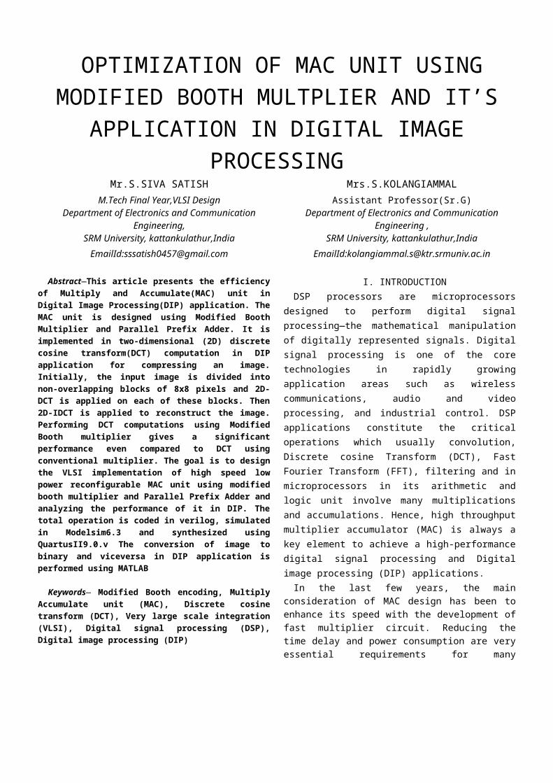
every aspects of our daily life such as communication broad casting, data search, advertisement, video games, etc, has become an integral part of our life style. The most significant part of multimedia systems is application involving image or video, which require computationally intensive data processing. Moreover, as the use of mobile device increases exponentially, there is a growing demand for multimedia application to run on these portable devices. A typical image/video transmission system is shown in the Figure 4.1.
Figure 4.1. Image/Video Transmission System
Multimedia files are large and consume lots of hard disk space. The files size makes it time-consuming to move them from place to place over school networks or to distribute over the Internet. Compression shrinks files, making them smaller and more practical to store and share. Compression works by removing repetitious or redundant information, effectively summarizing the contents of a file in a way that preserves as much of the original meaning as possible.
In order to reduce the volume of multimedia data over wireless channel compression techniques are widely used. Efficacy of a transformation scheme can be directly gauged by its ability to pack input data into as few coefficients as possible. This allows the quantizer to discard coefficients with relatively small amplitudes without introducing visual distortion in reconstructed image.
B. Discrete Cosine Transform
Discrete cosine transform (DCT) is one of the major compression schemes owing to its near optimal performance and has energy compaction efficiency greater than any other transform. The principle advantage of image transformation is the removal of redundancy between neighboring pixels. This leads to uncorrelated transform coefficients which can be encoded independently. DCT has that de correlation property.
Since the DCT is separable, 2-D can be obtained from two 1-D DCTs. The 2-D DCT equation is given by Equation 4.1
…………………………(4.1)For u,v= 0,1,2,…,N −1.
The inverse transform is defined by Equation 4.2
………………………….(4.2)For x,y= 0,1,2,…,N −1.
The 2-D basis functions can be generated by multiplying the horizontally oriented 1-D basis functions with vertically oriented set of the same functions.
In image compression, the image data is divided up into 8x8 blocks of pixels. A DCT is applied to each 8x8 block. DCT converts the spatial image representation into a frequency map. The low-order or "DC" term represents the average value in the block, while successive higher-order ("AC") terms represent the strength of more and more rapid changes across the width or height of the block. The highest AC term represents the strength of a cosine wave alternating from maximum to minimum at adjacent pixels.
C. Quantization
To discard an appropriate amount of information, the compressor divides each DCT output value by a quantization coefficient and rounds the result to an integer. The larger the quantization coefficient, the more data is lost. The higher order terms being quantized more heavily than the low-order terms with resulting coefficients containing a significant amount of redundant data. Huffman compression will lossless remove the redundancies, resulting in smaller data.
The human eye not capable of distinguishing the exact strength of a high frequency brightness variation so good. Hence we can greatly reduce the amount of information in the high frequency components. This is achieved by simply dividing each component in the frequency domain by a constant for that component, and then rounding to the nearest integer. This rounding operation is the only lossy operation in
the whole process if the DCT computation is performed with sufficiently high precision. As a result, many of the higher frequency components are rounded to zero, and many of the rest become small positive or negative numbers, which take many fewer bits to represent.
4. Entropy Encoding
Entropy coding is a form of lossless data compression. The steps involved in entropy encoding are arrangement of image components in a zigzag manner employing run length encoding (RLE) algorithm.
The transformation concentrates the information in the low frequency ranges allowing the high frequency with less or nil information being discarded.
In the designed MAC, a novel reconfigurable adder-based architecture for DA realizing the inner product which is the key computation in many digital signal processing applications was proposed. In ROM based DA architecture, the input signal correlations and quantization are exploited to reduce the arithmetic operation.
V. EXTENDED WORKA. Introduction
In the DCT process input image is divided into non overlapping blocks of 8 x 8 pixels, and input to the baseline encoder. The pixel values are converted from unsigned integer format to signed integer format, and DCT computation is performed on each block. DCT transforms the pixel data into a block of spatial frequencies that are called the DCT coefficients. Since the pixels in the 8 x 8 neighborhood typically have small variations in gray levels, the output of the DCT will result in most of the block energy being stored in the lower spatial frequencies. On the other hand, the higher frequencies will have values equal to or close to zero and hence, can be ignored during encoding without significantly affecting the image quality.
B. Frequency Coefficients
The selection of frequencies based on which frequencies are most important and which ones are less important can affect the quality of the final image. The selection of quantization values is critical since it affects both the compression efficiency, and the reconstructed image quality. High frequency coefficients have small magnitude for typical video data, which usually does not change dramatically between neighboring pixels. Additionally, the human eye is not as sensitive to high frequencies as to low frequencies. It is difficult for the human eye to discern changes in intensity or colors that occur between successive pixels. When the DCT is used for compression purposes, the quantizer unit attempts to force the insignificant high frequency coefficients to zero while retaining the important low frequency coefficients. 8-
point 1-D Discrete Cosine Transform implemented using Designed MAC unit
C. Decomposed Matrix
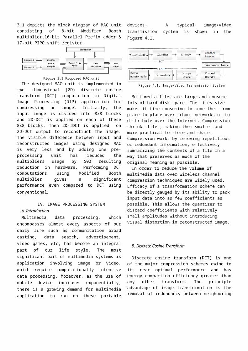
The 1-D 8-point DCT can be expressed as follows:
…(5.1)Where xm denotes the input data; Zn denotes the transform output; Kn = sqrt(1/2) for n=0 By neglecting the scaling factor 1/2, the above 1-D 8-point
DCT equation can be Divided into even and odd parts as
In 8 point DCT 8 input values are multiplied with 8 x 8 DCT matrix . For getting all 8 outputs 64 multipliers are used. In decomposed DCT architecture by adding one pre- processing unit we reduce the multipliers usage by 50% (only 32 multipliers used). In pre-processing unit we used only adders. Overall we can reduce the hardware complexity.
D. Binary Conversion
The two ways of floating point to binary conversion to implement DCT in VLSI are
1. Both integral and fractional part is converted separately by repeatedly multiply 2, and considers each one bit as
it appears left of the decimal.2. Representing the floating number using IEEE 754 format
(single or double precision).Method 1 can be used efficiently if we use any shift and add based approach for DCT computation.For method 2 we need to have floating point arithmetic unit for computation.
1) DCT coefficients pre-processingHere we preprocessed the DCT coefficients using
MATLAB in order to convert that into binary numbers which will be saved in text files. Later these values are used in DCT computation. These coefficient vales are multiply by some larger numbers and rounded into integer values. That number has to be 2’s multiplication values because later we can to do post processing simply by some right shifts. For example if we multiply by 1024 we can skip 10 least significant bits from the result.

574 x - 0.1913 = 109.8062 with removal of 10 LSB from the result. Here we preprocessed the coefficient value by
1024 x -0.1913= 195.8912 ~ -196.
2) Inverse DCT ArchitectureThe Inverse Discrete Cosine Transform (IDCT) is the
most computationally intensive portion of the image/ video decoder. Thus, it would be desirable, in terms of energy conservation, to use a low complexity approximate. The technique used here is the strength reduction which removes the redundant calculations
3) Odd And Even DCT AlgorithmThe 2-D IDCT is obtained by row column
decomposition. In inverse DCT, column wise transform is done first and the row transform is then applied on the transposed matrix of column transform output. Each 1-D IDCT is split into odd and even matrix as that of the direct 2-D DCT architecture. This reduces the complexity of the architecture. An N point inverse 2-D DCT is given by equation as below
…(5.2)where x(i, j) ,0≤i ,j≤N-1 is the reconstructed spatial data
sequence; X(u, v) , 0≤u,v≤N-1 is the transformed value and C(u),C(v) are given by equation below
……………(5.3)The 2-D DCT and 2-D IDCT can be written in a matrix
form as x= Tt X T ……………………….(5.4)where T is NxN cosine basis matrix an Tt is it’s transpose.
The block diagram of 2-D IDCT is shown in the Figure 5.1
Figure 5.1 Block Diagram of 2-D IDCT
The complexity of the design can be reduced by splitting the 1-D into odd and even matrix as done in direct DCT. The odd and even cosine matrix used in IDCT is the inverse of its counterpart in direct DCT. The odd 1-D IDCT matrix is given by Equation below
The even 1-D IDCT matrix is given by
VI. EXPERIMENTAL RESULTSThe design is scripted as a verilog file and synthesized
using QuartusII 9.0 v. The design is synthesized into Cyclone device. The image is converted into pixels using MATLAB and the values are stored as a text file. The text file is accessed by the Modelsim6.3v and the corresponding 2-D DCT coefficients are calculated. These values are then fed to the IDCT module which returns the spatial data sequence. These data are written to a text file. The image can be reconstructed from the text file using MATLAB coding.
The Area, speed and power comparision of Existing and proposed MAC unit is shown in table 2.
Table 2: Comparision of Array MAC and Booth MAC
Figure 6: RTL View of Booth MAC unit
A. Modelsim Generated Waves
Figure 6.1 Simulation Result of Designed MAC unit
Figure 6.2: Original Spatial Data Sequence(8x8)
Figure 6.3: 2-D DCT Coefficients(8x8)
Figure 6.4: Reconstructed Spatial Data Sequence(8X8)
Figure 6.5: Input Image(left) and Reconstructed Image(right)
VII. CONCLUSIONWe propose a unique high speed area efficient Modified
booth multiplier based MAC unit to improve throughput rate and to minimize the area complexity of 8x8 2D-DCT

architecture. In the DCT architecture, DCT computation is performed with sufficiently high precision in DCT matrix multiplication yielding an acceptable quality. Our proposed MAC architecture achieves a maximum operating frequency 270.93 MHz and optimized synthesis results .In summary the proposed architecture is suitable for applications in HDTV system.
REFERENCES[1] Pratap Kumar.D,Anamika Sinha,Shivdhari and Gourab, Hardware
Implementation of MAC unit, International Journal of Electronics Communication and Computer Engineering, 2012,vol.3
[2] Sandeep, Shrivastava, Jaikaran Singh and Mukesh Tiwari, “Implementation of Radix-2 Modified Booth Multiplier and comparision with Radix-4 Encoder Booth Multiplier”, International Journal of Emerging Tecnologies2(1):14-16,2011.
[3] Deepali Chandel, Gagan Kumawat, Pranay Lahoty,Vart Chandrodaya, Shailendra Sharma, Modified Booth Multiplier: Ease of multiplication, International Journal of Emerging Technology and Advanced Engineering Website: www.ijetae.com (ISSN 2250-2459, ISO 9001:2008 Certified Journal, Volume 3, Issue 3, March 2013)
[4] A.Abdelgawad, Low Power Multiply Accumulate Unit (MAC) for Future Wireless Sensor Networks, School of Engineering & Technology Central Michigan University Mount Pleasant, MI 48859, USA.
[5] Yung-Pin Lee,Thou-Ho Chen, Liang-Gee Chen, Mei-Juan Chen and Chung-Wei Ku, "A Cost-Effective Architecture for 8X8 Two-Dimensional DCT/IDCT Using Direct Method ", IEEE Transactions on circuits and systems for video technology, vol. 7, no. 3, june 1997
[6] Andrew B. Watson, “ Image Compression Using the Discrete Cosine Transform” NASA Ames Research Center Mathematical Journal, 4(1), 1994, p. 81-88.
[7] Prabhakar.Telagarapu, V.Jagan Naveen, A.Lakshmi..Prasanthi, G.Vijaya Santhi, “Image Compression Using DCT and Wavelet Transformations” International Journal of Signal Processing, Image Processing and Pattern Recognition Vol. 4, No. 3, September, 2011.
[8] Rafael C. Gonzalez and Richard E.Woods, Digital Image Processing,Pearson Education, Second Edition.
[9] Rafael C. Gonzalez, Richard E. Woods and Steven L.Eddins “Digital Image Processing using MATLAB”, Pearson Education
[10] V.Alarcon-Aquino, J.M.Ramirez-Cortes, P.Gomez-Gil, O.Starostenko and H. Lobato-Morales, Lossy Image Compression Using Discrete Wavelet Transform and Thresholding Techniques, The Open Cybernetics & Systemics Journal, 2013, 7, 32-38