Design Of baseband Processor for High Dynamic GPS …ijmlc.org/papers/77-A781.pdf · Locked Loop)...
6
Abstract—Traditional GPS receivers work well when the relative dynamics between the receiver and the satellites are less, i.e., low Doppler and Doppler rate. However, in high dynamic environments the receivers no longer track the signals resulting in the loss-of-lock of GPS position, velocity and time. Typical Doppler range in conventional receiver is ±7 KHz and the Doppler rate is1Hz/s, whereas in high dynamics the Doppler frequency is expected to vary in the ranges ±25KHz with Doppler rates of about 100Hz/s. Therefore, it is a challenging task to develop algorithms to receive signals under high dynamics. To solve this problem, a new frequency-locked loop (FLL) assisted phase-locked loop (PLL) technique of higher order is introduced in this paper. Second order FLL reduces the locking time by frequency pulling and thus rectifies the higher dynamic frequency errors at the receiver and allows the third order PLL to lock on to the dynamically changing phase of the signal with high accuracy. The proposed algorithm was implemented using Matlab/Simulink and evaluated by simulated data sets. Results show that the proposed algorithm of using higher order frequency loop has improved performance when the input signal changes comprise large dynamics. Index Terms—Baseband processor, GPS, high dynamics, higher order loop. I. INTRODUCTION U.S. space-based radio navigation system called Global Positioning System (GPS) provides real-time navigation, positioning and timing services to military and civilian users. Position, Velocity in 3-dimensional co-ordinates and GPS time of the user receiver are the key parameters that are obtained from a GPS receiver. In the traditional GPS system, all satellites broadcast two frequencies, L1 signal at 1.57542 GHz and L2 signal at 1.2276 GHz. In GPS we use CDMA spread-spectrum technique for satellite network, where low-bit rate message data is encoded with high-rate pseudo-random (PRN) sequence which is unique for each satellite. This is spread out within a data bit interval of 20ms at receiver side. By demodulating the data and combining it with the pseudo-range and delta pseudo-range the receiver will provide the position, velocity and time. However, GPS receivers are prone to radio interference and jamming because it relies on electromagnetic signals for receiving the satellite signals. Hindrances like buildings and trees can avert the signal thereby causing position on the GPS screen to be off by as much as 100 feet. It does not work indoors, under water, in tunnels, underground and in large Manuscript received October 24, 2011, revised November 04, 2011. Sidhant Kumar Tiwari is currently working with L&T Infotech as a Software Engineer in the J2EE domain. (E-mail id: [email protected]) cities (skyscraper canyons) due to lack of continuous radio access to the satellites. Another disadvantage of GPS is the global coverage of the Earth with signals from GPS is not equally distributed in all areas. The inclination of GPS satellite orbits compared to the equator (55°) yields good coverage of the USA and most continents, but a less good coverage at Northern and Southern latitudes. Scandinavian countries, Canada and the North of Russia are affected. Moreover, the receiver also fails working in high dynamic scenarios as the apparent change in Doppler frequency and Doppler frequency rates are very high due to the high dynamics of the vehicle. For a stationary receiver, the Doppler range is ±7KHz whereas this range extends up to ±100 KHz in a high dynamic receiver.GPS signals are not always completely accurate. Fig. 1. Basic GPS receiver Thus tracking dynamics on the GPS signal is still a big challenge to the receiver designer as the operating conditions are becoming more volatile. Optimizing the stand-alone system for dynamics generally degrades the accuracy of measurements. Therefore, an inertial navigation system (INS) is integrated with GPS receiver to address this issue [1]. However, this is an expensive solution which may not be feasible for low cost applications. A typical block diagram is shown in the Figure 1[2]. In the basic GPS receiver the signals transmitted from the GPS satellites are received by the antenna and processed by the digital processor. RF chain does the frequency and amplitude conversion of the received signal which is then digitized and given to the acquisition block. The acquisition block determines the absence or presence of the satellite signals under Doppler effects caused due to the relative motion between the satellite and the receiver. The tracking algorithm consists of DLL (Delay Locked Loop) and Costas Phase Locked Loop (CPLL) which will take the coarse values of the signal from the acquisition loops to extract fine-tuned 50Hz navigation data [3]. Ephemeris and Almanac parameters of navigation data helps in determining the positions of satellite and eventually helps in calculation the user position. In this paper, we propose a simple algorithm for rectifying Design Of baseband Processor for High Dynamic GPS Signals Using Higher Order Loops Sidhant Kumar Tiwari, Swarna Ravindra Babu and R Kumar International Journal of Machine Learning and Computing, Vol. 1, No. 5, December 2011 516
Transcript of Design Of baseband Processor for High Dynamic GPS …ijmlc.org/papers/77-A781.pdf · Locked Loop)...
Abstract—Traditional GPS receivers work well when the
relative dynamics between the receiver and the satellites are less, i.e., low Doppler and Doppler rate. However, in high dynamic environments the receivers no longer track the signals resulting in the loss-of-lock of GPS position, velocity and time. Typical Doppler range in conventional receiver is ±7 KHz and the Doppler rate is1Hz/s, whereas in high dynamics the Doppler frequency is expected to vary in the ranges ±25KHz with Doppler rates of about 100Hz/s. Therefore, it is a challenging task to develop algorithms to receive signals under high dynamics. To solve this problem, a new frequency-locked loop (FLL) assisted phase-locked loop (PLL) technique of higher order is introduced in this paper. Second order FLL reduces the locking time by frequency pulling and thus rectifies the higher dynamic frequency errors at the receiver and allows the third order PLL to lock on to the dynamically changing phase of the signal with high accuracy. The proposed algorithm was implemented using Matlab/Simulink and evaluated by simulated data sets. Results show that the proposed algorithm of using higher order frequency loop has improved performance when the input signal changes comprise large dynamics.
Index Terms—Baseband processor, GPS, high dynamics, higher order loop.
I. INTRODUCTION U.S. space-based radio navigation system called Global
Positioning System (GPS) provides real-time navigation, positioning and timing services to military and civilian users. Position, Velocity in 3-dimensional co-ordinates and GPS time of the user receiver are the key parameters that are obtained from a GPS receiver. In the traditional GPS system, all satellites broadcast two frequencies, L1 signal at 1.57542 GHz and L2 signal at 1.2276 GHz. In GPS we use CDMA spread-spectrum technique for satellite network, where low-bit rate message data is encoded with high-rate pseudo-random (PRN) sequence which is unique for each satellite. This is spread out within a data bit interval of 20ms at receiver side. By demodulating the data and combining it with the pseudo-range and delta pseudo-range the receiver will provide the position, velocity and time.
However, GPS receivers are prone to radio interference and jamming because it relies on electromagnetic signals for receiving the satellite signals. Hindrances like buildings and trees can avert the signal thereby causing position on the GPS screen to be off by as much as 100 feet. It does not work indoors, under water, in tunnels, underground and in large
Manuscript received October 24, 2011, revised November 04, 2011. Sidhant Kumar Tiwari is currently working with L&T Infotech as a Software Engineer in the J2EE domain. (E-mail id: [email protected])
cities (skyscraper canyons) due to lack of continuous radio access to the satellites. Another disadvantage of GPS is the global coverage of the Earth with signals from GPS is not equally distributed in all areas. The inclination of GPS satellite orbits compared to the equator (55°) yields good coverage of the USA and most continents, but a less good coverage at Northern and Southern latitudes. Scandinavian countries, Canada and the North of Russia are affected.
Moreover, the receiver also fails working in high dynamic scenarios as the apparent change in Doppler frequency and Doppler frequency rates are very high due to the high dynamics of the vehicle. For a stationary receiver, the Doppler range is ±7KHz whereas this range extends up to ±100 KHz in a high dynamic receiver.GPS signals are not always completely accurate.
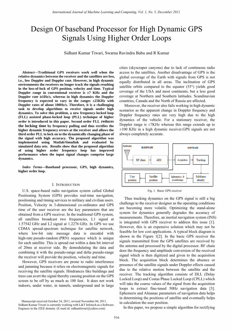
Fig. 1. Basic GPS receiver
Thus tracking dynamics on the GPS signal is still a big challenge to the receiver designer as the operating conditions are becoming more volatile. Optimizing the stand-alone system for dynamics generally degrades the accuracy of measurements. Therefore, an inertial navigation system (INS) is integrated with GPS receiver to address this issue [1]. However, this is an expensive solution which may not be feasible for low cost applications. A typical block diagram is shown in the Figure 1[2]. In the basic GPS receiver the signals transmitted from the GPS satellites are received by the antenna and processed by the digital processor. RF chain does the frequency and amplitude conversion of the received signal which is then digitized and given to the acquisition block. The acquisition block determines the absence or presence of the satellite signals under Doppler effects caused due to the relative motion between the satellite and the receiver. The tracking algorithm consists of DLL (Delay Locked Loop) and Costas Phase Locked Loop (CPLL) which will take the coarse values of the signal from the acquisition loops to extract fine-tuned 50Hz navigation data [3]. Ephemeris and Almanac parameters of navigation data helps in determining the positions of satellite and eventually helps in calculation the user position.
In this paper, we propose a simple algorithm for rectifying
Design Of baseband Processor for High Dynamic GPS Signals Using Higher Order Loops
Sidhant Kumar Tiwari, Swarna Ravindra Babu and R Kumar
International Journal of Machine Learning and Computing, Vol. 1, No. 5, December 2011
516

the higher dynamic frequency errors at the receiver over the other conventional methods. We adopted FLL (Frequency Locked Loop) assisted PLL (Phase Locked Loop) architecture i.e. second order FLL in assistance with third order PLL for optimized performance [4, 5].
The conventional methods used for tracking high dynamic signals such as, second order PLL assisted first order FLL cannot detect the jerk and acceleration stress [6]. Similarly, extended Kalman filter is used to track a common trajectory exhibiting high dynamics [7], but the filter may quickly diverge owing to its linearization if the initial state of estimates is out of bounds. But in proposed technique the FLL shall reduce the locking times by frequency pull; avert false locks and enables tracking of spread spectrum signals in high dynamic environment. This pre correction of second order FLL over a wide bandwidth allows the third order PLL to lock on to the dynamically changing phase of the signal with high accuracy. Frequency pulling of FLL also helps in narrowing the pass band of the PLL to suppress the noise thereby helping the PLL to lock down the phase of carrier with high precision and accuracy. PLL’s of first and second order have the capability to track only phase and frequency steps, whereas the third order PLL enables the tracking of frequency ramp [8], which will be effectively used in tracking the high dynamic signals. For reliable carrier phase tracking, the loop bandwidth of PLL should be low. An increase in loop bandwidth of PLL increases the noise, whereas dynamic tracking errors increase with decrease in loop bandwidth [9]. Thus the loop bandwidth of carrier must be sharp enough so that reliable carrier phase tracking of acceleration and jerk (the derivative of acceleration) of less than 5 g and 5g/s takes place respectively.
This proposed technique is completely exercised on MATLAB Simulink platform. Simulink provides an independent code conversation of the implemented codes of (MATLAB functions, Simulink diagrams and State flowcharts) into C and C++ code. Taking advantage of which real time applications can be developed. Another advantage of using this platform is, it can be easily interfaced with Xilinx system generator which will translate a Simulink model into a hardware realization of the model.
II. TRACKING ANALISISFOR HIGH DYNAMICS High dynamics mean large values for velocity and its
derivatives. Basically there are two high-dynamic trajectories – one that simulates linear acceleration and other that simulates circular motion. Linear trajectory presumes a constant acceleration throughout, and the circular trajectory delineates the velocity and its derivatives as sine waves, corresponding to motion in a circle [10]. Using conventional GPS receivers it is difficult to track these high dynamic trajectories. The effect of dynamics on individual tracking channel is governed completely by relative geometry of the GPS system. Each channel visualizes the velocity and acceleration drift that is along the line of sight between the receiver and the satellite. As this element is always less than or equal to the total dynamics, the pressure on each channel is not as severe as signaled by the overall dynamics.
The GPS satellites transmit pseudorandom sequence i.e. C/A code at L1-band frequency. This code is bi-phase
modulated at 50 bit/s and each satellite uses this pseudorandom signal with a period of 1023 chips clocked at 1.023 MHz’s. The receiver uses separate code and carrier phase-lock loops to track time delay, carrier frequency and phase in order to estimate pseudo-range and range rate respectively. The Doppler shift on the carrier frequency, fd, and on the code frequency, fdc, are given as
= 1 (1)
fdc = fcode (2)
where is the range rate between the satellite and the receiver, c is the speed of light, fL1is the L1 carrier frequency, and fcode is the C/A code frequency. The Doppler frequency on the carrier and code signals are related by
fdc = -fcode (3)
The equation (2) represents the change in the code delay.
The amount of the change in the code delay ∆ τ in T sec is given by
∆τ =-T (4)
The acquisition algorithms estimate an approximate Doppler shift fd and code delay τ to provide the In-phase and Quadrature signals as given in equations (5) and (6)
Ii = AdiR(τei) sinc((fei + αe ) ) cos(θei) + nIi (5) Qi =AdiR(τei) sinc((fei + αe ) ) sin(θei) + nIi (6)
where τei is the code delay error at the ith interval, fei is the Doppler shift estimation error at the beginning of the ith interval αe is the Doppler rate estimate error, θei is the average phase error and is the C/A code length modified by the Doppler effect at ith interval. The length is defined by
and , respectively. If the received signal is of low dynamics then both the received code and the data bit are assumed to have constant lengths. A change in the Doppler shift causes a change in the code length, so the code and the data bit length are not the same in each interval. They are calculated using equations (7) and (8) as given in
= (7)
= (8)
where fdo is the estimate Doppler shift at the start of algorithm & Tc and Td are actual code and data bit length. In the case of high dynamics, after a certain number of updates based on the Doppler rate value Tc and Td are calculated. Simplifying the in-phase and quad phase components of equations (5) and (6) yields
Ik =Ak.dk.cos(θk) + ni,k (9)
Qk =Ak.dk.sin(θk) + nq,k (10)
International Journal of Machine Learning and Computing, Vol. 1, No. 5, December 2011
517

where dk is the data bit associated with the time index k,θk is the phase error, nik & nqk are noise on I & Q samples which are assumed to be white Gaussian noise, and Ak is the signal level. Assuming that the acceleration along the line-of sight is constant, the Doppler frequency on the incoming signal can be expressed as
fd(t) = f v+ fat (11)
where fd is the overall Doppler frequency in the incoming signal, f v is the frequency shift caused by relative velocity. fa is the change rate of frequency shift caused by acceleration along line of sight between satellite and receiver. The Doppler frequency over a period of ∆t is obtained as fd(t + ∆t ) = fv(t) + fa ∆t (12)
and the carrier phase variation caused by the Doppler frequency in the incoming signal over a period of ∆t is
∆θ = ∆ (t+τ)dτ = fv∆t + fa∆ (13)
The tracking ability of PLL depends on the order of the loop. While the first order loop (no loop filter) cannot track a frequency ramp excitation signal (acceleration), the second order loop can track but with a constant phase difference. Moreover, the third order loop can track a frequency ramp excitation signal (acceleration) with no phase difference. Under high dynamic conditions, Δθ will be affected by noise which is caused by the carrier movement.
A. Tracking Architecture In figure 2, the FLL assisted PLL architecture is shown.
This architecture uses second order FLL and third order PLL to provide optimized performance during high dynamic vehicle trajectories. A FLL of second order tracks the higher dynamics carrier signal but fails to provide carrier phase information; in contrast, a higher order PLL can track carrier
Fig. 2. Second order FLL assisted with third order PLL
B. Discriminator Algorithm The paradox involved in the GPS receiver design to
tolerate dynamic stress is: the prediction integration time should be short, the discriminator should be FLL and carrier loop bandwidth should be wide. However for the carrier Doppler phase measurement to be accurate and low noisy, the prediction integration time should be long, the discriminator should be PLL and carrier loop bandwidth should be narrow.
1) PLL discriminator The linear behavior shown by the two quadrant ATAN
discriminator over half the error range of ±90˚ enables it to be an optimum PLL discriminator for carrier tracking irrespective of high and low SNR. The equation for phase discriminator is given as
Phase Discriminator = ( ⁄ ) (14)
where phase error is given as φ. Till the PLL maintains its phase lock, the phase ambiguity
remains in the resolved state. But when the PLL loses or slip cycles, i.e. comes out of the lock, the ambiguity should be resolved again. The 180˚ ambiguity is further resolved by referring to the phase detection result of data bit modulation. The Doppler phase, hence indicated by the PLL stands correct, if the bit phase is normal. But if the phase is inverted, 180˚ phase PLL adds towards resolving the phase ambiguity. PLL, though being sensitive to dynamic stress produces most accurate velocity measurements. However, a well-designed GPS receiver will close the loop with more robust FLL operated at wideband.
2) FLL discriminator FLL, also called the automatic frequency control (AFC)
loops owing to the fact that it replicates the approximate frequency, performs carrier wipe off. Initially, signal acquisition receiver doesn’t know about the data transition limits; hence it is very easy to maintain frequency locks as compared to phase locks. Because in situations where some of I & Q signals do straddle the data bit transitions, FLL discriminator are less sensitive as compared to PLL [4]. Thus carrier loop discriminator uses FLL discriminators even though PLL and Costas loop discriminators are more accurate since they are highly sensitive to dynamic stress. The discriminator used for the FLL is
Frequency Discriminator = ( , )( ) ˚ (15)
where Dot =IPS1.IPS2 + QPS1.QPS2
Cross=IPS1.QPS2 - IPS2.QPS1
and the frequency error is given as
Frequency error =( ) ˚ (16)
3) DLL discriminator The code dynamics are significantly overshadowed by the
carrier dynamics since the code frequency is 1/1540 times lesser than the carrier frequency. Therefore to calculate the code frequency the following DLL discriminator algorithm is used which is given as:
The Doppler frequency over a period of ∆t is obtained as
∑ ( ) ∑ ( )∑ ( ) ∑ ( ) (17)
International Journal of Machine Learning and Computing, Vol. 1, No. 5, December 2011
518
C. Mathematical Model of the Loop The Loop filter is mainly used to reduce the noise in order
to reduce the noise in order to produce an accurate estimate of the original signal at its output. And the order and the noise bandwidth of the loop filter determine the loop filters response to signal dynamic. The loop filter’s output is effectively subtracted from the original signal to produce an error signal. This is feedback into the filter’s input in a closed loop process. First order loop filter are rarely used for tracking as they are Sensitive to velocity stress and also unconditionally stable at all noise bandwidths. Also can’t be used in unaided code loops.
1) Second order tracking loop The second order loop filter is sensitive to stress due to
acceleration, and is utilized in aided and unaided carrier loops. For tracking, FLL of second order is selected with a noise bandwidth of 0.25 Hz for carrier loop filter and 2Hz for code loop filter. The transfer function of this filter is given as [1], and the carrier phase variation caused by the Doppler frequency in the incoming signal over a period of ∆t is
( ) = or + (18)
In terms of damping frequency and natural frequency ( ) = 2 + (19)
and the overall system transfer function is provided in the equation (18) ( ) = (20)
Gives ( ) = (21)
where = , 2 = & = the relationship between the natural frequency and damping frequency is given as
= ( + ) (22)
Thus transfer function for carrier loop with Bn= 0.25Hz is given by
( ) = . . . . (23)
and transfer function for code loop with Bn= 2Hz is given by
( ) = . . . . (24)
where is the natural frequency, is the damping frequency i.e. 0.707 & Bn= 0.53
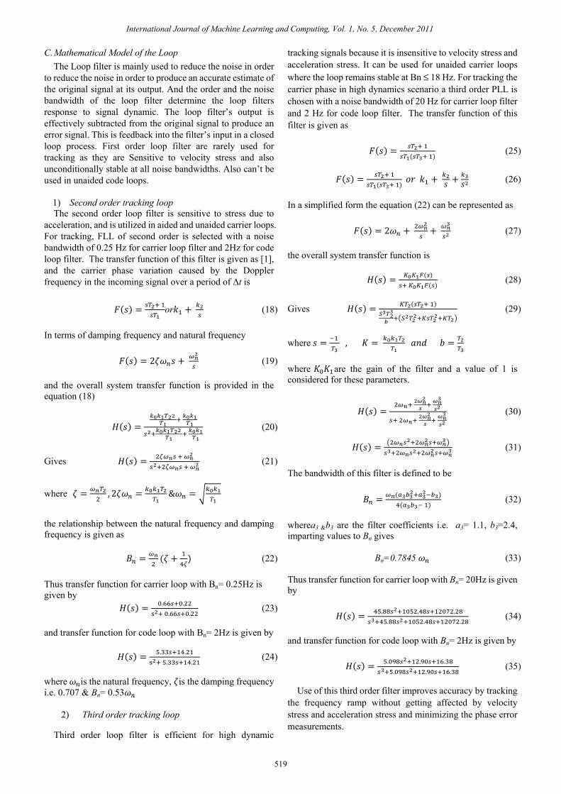
2) Third order tracking loop
Third order loop filter is efficient for high dynamic
tracking signals because it is insensitive to velocity stress and acceleration stress. It can be used for unaided carrier loops where the loop remains stable at Bn ≤ 18 Hz. For tracking the carrier phase in high dynamics scenario a third order PLL is chosen with a noise bandwidth of 20 Hz for carrier loop filter and 2 Hz for code loop filter. The transfer function of this filter is given as
( ) = ( ) (25)
( ) = ( ) + + (26)
In a simplified form the equation (22) can be represented as
( ) = 2 + + (27)
the overall system transfer function is
( ) = ( ) ( ) (28)
Gives ( ) = ( ) (29)
where = , = =
where are the gain of the filter and a value of 1 is considered for these parameters.
( ) = (30)
( ) = (31)
The bandwidth of this filter is defined to be
= ( )( ) (32)
wherea3 &b3 are the filter coefficients i.e. a3= 1.1, b3=2.4, imparting values to Bn gives
Bn=0.7845 (33)
Thus transfer function for carrier loop with Bn= 20Hz is given by
( ) = . . .. . . (34)
and transfer function for code loop with Bn= 2Hz is given by
( ) = . . .. . . (35)
Use of this third order filter improves accuracy by tracking the frequency ramp without getting affected by velocity stress and acceleration stress and minimizing the phase error measurements.
International Journal of Machine Learning and Computing, Vol. 1, No. 5, December 2011
519

III. SIMULATION RESULT AND ANALYSIS A software simulation of the receiver was performed to
independently affirm theoretical and experimental performance of GPS receiver using higher order loop for high dynamics tracking.
The reference trajectory used to simulate GPS measurements is shown in the figure 3. A constant velocity trajectory of 100m/s in the east direction is chosen for the initial experiments. A GPS transmitter system was developed in Matlab which uses this trajectory as an input. The trajectory information was converted into Doppler data which modules both the PRN code and carrier frequency. The carrier frequency was generated at 21.25MHz with a sampling frequency of 5MHz.
Fig. 3. reference trajectory used for simulation
The simulation result in figure 4 reveals the response of the
transfer function of third order PLL which was taken as a division of tracking module for tracing the frequency ramp and showing smaller error variations and less sensitivity to velocity stress and acceleration.
Fig. 4. response of third order transfer function
A high dynamic data with an acceleration of 50g was taken
and executed on the proposed model. The results of “the second order FLL assisted third order PLL” in figure 5 indicates a crystallize response by tracking the navigation data in terms of in phase (I) and quadrature phase (Q) component. The signal processing in the architecture is carried out in such an efficient way that entire signal power is possessed by I component and Q component contains only AWGN.
Fig. 5. In-phase and quad phase component of tracking output
Component I is noticed to be sequence of values occurring once per millisecond or 20 times per data bit. Each data bit is generated by integrating the I component over 20-ms interval from one data bit boundary to other. All boundaries are bit synchronized to extract the information for navigation solution.
IV. CONCLUTION This work articulates an optimized higher order receiver
which efficiently works well in severe dynamic environment where normal receiver loses lock. This composition of frequency-locked loop (FLL) assisted phase-locked loop (PLL) technique precisely rectifies high dynamic frequency error and helps in locking the phase of high dynamic signal with sharp accuracy. The computer simulation result has verified the theoretical analysis by filtering the navigation data in terms of I and Q phase component from high dynamic signal.
ACKNOWLEDGEMENT
I would like to thank Dr. Swarna Ravindra Babu (senior consultant) Advance technology Laboratory, WIPRO Technologies Chennai, for all his support and guidance throughout this project.
REFERENCES
[1] Ravindra Babu, Wang Jinling, Analysis of Inertial Navigation System derived Doppler effects on carrier tracking loop, Journal of Navigation, vol. 58, p.493-507,Issue 3,09/2005.
[2] James Bao-Yen Tsui. “Fundamentals of global positioning system receivers: a software approach,” John Wiley & Sons, Inc. 2nd Edition, 2004.
[3] M S Grewal “Global positioning system, inertial navigation and integration” Copyright 2001 @ John Wiley & Sons, Inc.
[4] Kaplan E D. “Understanding GPS principles and applications”. USA: Artech House, 1996.
[5] Nesreen I .Ziedan “GNSS receiver for weak signals” ARTECH HOUSE, INC. 685 Canton Street Norwood.
[6] Wenmiao Song ,JingyingZhang,Hanbai Fan “Research on the digital carrier tracking technique for high dynamic spread spectrum Receiver” IEEE International Conference on Networks Security, Wireless Communications and Trusted Computing, 26 April 2009, P. 419 - 422
[7] Lin Zhao, Jicheng Ding, Shu Yu, “All-digital gps signal simulating and processing techniques for high dynamic movement”, IEEE International Workshop on Modeling, Simulation and Optimization, WMSO, 28 Dec 2008, P. 428 – 432.
[8] Hurd, W. J., Statman, J. I., and Vilnrotter, V. A. “High dynamic gps receiver using maximum likelihood estimation and frequency tracking”
12
34
56
78
910
-10
1-1
0
1
up (k
m)
Flight Path
north (km)
east (km)
0 500 1000 1500 2000 2500-3
-2.5
-2
-1.5
-1
-0.5
0 x 106
frequency Hz
gain
dB
Response of third order loop filter
0 50 100 150 200 250-2
-1.5
-1
-0.5
0
0.5
1
1.5
2 x 10⁴
time (ms)
ampl
itude
Navigation data extracted
In-phaseQuadrature phase
International Journal of Machine Learning and Computing, Vol. 1, No. 5, December 2011
520

IEEE Transactions on Aerospace and Electronic Systems, AES-23, 4 July 1987, p.425-437.
[9] Pedro A. Roncagliolo, CristianE.DeBlasis, and Carlos H. Muravchik, "GPS digital tracking loops design for high dynamic launching vehicles," IEEE Ninth International Symposium on Spread Spectrum Techniques and Applications, UNLP, CC 91, 1900, IEEEPress, 2006, pp.41-45.
[10] S. Hinedi & J. I. Statman “High-dynamic gps tracking” JPL Publication 88-35 December 15, 1988.
Sidhant Kumar Tiwari was born at Portblair, Andaman & Nicobar Island, India on 23rd August 1988. He received the Bachelor’s degree in Electronics and Communication Engineering from Vinayaka Missions University, Tamilnadu, India, in 2009, the Master’s degree in Communication Systems Engineering from SRM University, Tamilnadu, India, in 2011.
He is working as a Software Engineer in L&T InfoTech. His research interest is Optimization of GPS receiver using higher loops, GNSS multi-constellation baseband receiver for high dynamic application, Software Defined Radio, Wireless and Mobile Network communication.
Dr. Swarna Ravindra Babu was born at Chennai, Tamilnadu on 24th September 1971. He completed his PhD from UNSW, Australia specializing in the integration of GPS and INS systems. He has about 15 years of experience in R & D organizations with expertise in the areas of RF, DSP, GPS, Communication Systems and Statistical Signal Processing. He has published more than 70 papers in Journals and
Conferences. He is currently heading a group working on the next generation
developments in the GNSS field. He has guided about 20 Master’s students and currently guiding 2 PhD students. His areas of interest include next generation GNSS and Wireless Technologies.
Dr. R Kumar was born at Eroad, Tamilnadu India on 2nd April 1968. He received the Bachelor’s degree in Electronics and Communication Engineering from Bharathidasan University, Tamilnadu, India, in1989, the Master of Science in 1993 from BITS, Pilani and PhD degree from SRM University, Chennai in 2009.
He is working as a professor in the department of electronics and communication engineering, SRM University, Chennai, India. He has 15 publications in
Indian and International journals. He is currently guiding 6 PhD students. His areas of interest include spread spectrum techniques, wireless communication, cognitive radio, wireless sensor networks and MIMO-OFDM systems.
International Journal of Machine Learning and Computing, Vol. 1, No. 5, December 2011
521