DESIGN OF AN AUTOCLAVABLE ACTIVE CANNULA …
5
1 Copyright © 2011 by ASME 2011 Design of Medical Devices Conference DMD2011 April 12th-14th, 2011, Minneapolis, MN, USA DMD2011 - 5308 DESIGN OF AN AUTOCLAVABLE ACTIVE CANNULA DEPLOYMENT DEVICE Trevor L. Bruns Vanderbilt University Nashville, TN, USA John M. Tucker Vanderbilt University Nashville, TN, USA D. Caleb Rucker Vanderbilt University Nashville, TN, USA Philip J. Swaney Vanderbilt University Nashville, TN, USA Emad M. Boctor Johns Hopkins University Baltimore, MD, USA Everette C. Burdette Acoustic MedSystems Inc., Urbana-Champaign, IL, USA Jessica Burgner Vanderbilt University Nashville, TN, USA Robert J. Webster III Vanderbilt University Nashville, TN, USA ABSTRACT Concentric tube continuum devices, known as active cannulas, consist of multiple pre-curved elastic tubes that extend telescopically and rotate axially with respect to each other. Through these degrees of freedom, an active cannula presents a dexterous and versatile “tentacle-like” mechanism for accessing targets in minimally invasive surgery. Deploying an active cannula in a practical surgical setting requires a sterilizable device capable of specifying positions and trajectories for each degree of freedom. While robotic devices will likely enable this to be done most efficiently in the future, initial clinical feasibility studies are best undertaken with manual devices. In this paper we present specifications, design and development of a manual (that is, not motorized) active cannula deployment device. INTRODUCTION One of the most common surgical tasks is reaching a specific, predefined location within the human body in order to deliver drugs, perform biopsy or deliver therapy (e.g. thermal ablation) [1,2]. Minimally invasive techniques often utilize needles, which in current clinical practice require a straight access path. Recent developments in needle steering enable curved insertion trajectories and control of needle path [3-7]. A drawback of these devices is that they must be embedded in tissue to steer, and use the tissue itself to enable steering. Thus, needle trajectory models (and hence control techniques) require accurate knowledge of tissue mechanical properties and boundary conditions (see e.g. [8,9]). Obtaining this information with a sufficient level of fidelity is an open research question. Also, incorporating inhomogeneous material properties into needle models is an open research challenge. Lastly, these steerable needles are not able to steer through open space or liquid-filled cavities. These factors in part inspired concentric tube devices, i.e. active cannulas, which provide dexterity in a needle-sized package, without requiring tissue reaction forces in order to steer [10-14]. A second advantage is that the active cannula design permits control of needle shaft shape as well as direction of forward tip progression (most prior steerable needle designs consider only the latter). An active cannula consists of elastic pre-curved tubes that extend telescopically and rotate axially with respect to each other. Figure 1 shows an Active Cannula and its degrees of freedom. Prior work on active cannula actuation units, with the exception of [15-16], has focused on robotic actuation. While robotic devices are desirable in the long-term to coordinate many degrees of freedom rapidly, manual actuation is also desirable for 1) initial clinical proof of concept in human cases (IRB and FDA approval of robotic devices is clearly much more challenging than for manual devices), and 2) cases where Figure 1: A three tube active cannula composed of concentric, pre-curved Nitinol tubes. Each tube provides two degrees of freedom.
Transcript of DESIGN OF AN AUTOCLAVABLE ACTIVE CANNULA …

1 Copyright © 2011 by ASME
2011 Design of Medical Devices Conference DMD2011
April 12th-14th, 2011, Minneapolis, MN, USA
DMD2011 - 5308
DESIGN OF AN AUTOCLAVABLE ACTIVE CANNULA DEPLOYMENT DEVICE
Trevor L. Bruns Vanderbilt University Nashville, TN, USA
John M. Tucker Vanderbilt University Nashville, TN, USA
D. Caleb Rucker Vanderbilt University Nashville, TN, USA
Philip J. Swaney Vanderbilt University Nashville, TN, USA
Emad M. Boctor Johns Hopkins University
Baltimore, MD, USA
Everette C. Burdette Acoustic MedSystems Inc.,
Urbana-Champaign, IL, USA
Jessica Burgner Vanderbilt University Nashville, TN, USA
Robert J. Webster III Vanderbilt University Nashville, TN, USA
ABSTRACT Concentric tube continuum devices, known as active cannulas, consist of multiple pre-curved elastic tubes that extend telescopically and rotate axially with respect to each other. Through these degrees of freedom, an active cannula presents a dexterous and versatile “tentacle-like” mechanism for accessing targets in minimally invasive surgery. Deploying an active cannula in a practical surgical setting requires a sterilizable device capable of specifying positions and trajectories for each degree of freedom. While robotic devices will likely enable this to be done most efficiently in the future, initial clinical feasibility studies are best undertaken with manual devices. In this paper we present specifications, design and development of a manual (that is, not motorized) active cannula deployment device.
INTRODUCTION One of the most common surgical tasks is reaching a specific, predefined location within the human body in order to deliver drugs, perform biopsy or deliver therapy (e.g. thermal ablation) [1,2]. Minimally invasive techniques often utilize needles, which in current clinical practice require a straight access path. Recent developments in needle steering enable curved insertion trajectories and control of needle path [3-7]. A drawback of these devices is that they must be embedded in tissue to steer, and use the tissue itself to enable steering. Thus, needle trajectory models (and hence control techniques) require accurate knowledge of tissue mechanical properties and boundary conditions (see e.g. [8,9]). Obtaining this information with a sufficient level of fidelity is an open research question. Also, incorporating inhomogeneous material properties into needle models is an open research challenge. Lastly, these
steerable needles are not able to steer through open space or liquid-filled cavities.
These factors in part inspired concentric tube devices, i.e. active cannulas, which provide dexterity in a needle-sized package, without requiring tissue reaction forces in order to steer [10-14]. A second advantage is that the active cannula design permits control of needle shaft shape as well as direction of forward tip progression (most prior steerable needle designs consider only the latter). An active cannula consists of elastic pre-curved tubes that extend telescopically and rotate axially with respect to each other. Figure 1 shows an Active Cannula and its degrees of freedom.
Prior work on active cannula actuation units, with the exception of [15-16], has focused on robotic actuation. While robotic devices are desirable in the long-term to coordinate many degrees of freedom rapidly, manual actuation is also desirable for 1) initial clinical proof of concept in human cases (IRB and FDA approval of robotic devices is clearly much more challenging than for manual devices), and 2) cases where
Figure 1: A three tube active cannula composed of concentric, pre-curved Nitinol tubes. Each tube provides two degrees of freedom.

2 Copyright © 2011 by ASME
a small number of tubes are required, and the tubes need not move dynamically. In [15,16] we performed preliminary studies related to one such application, namely thermal ablation of large liver tumors. However, the manual actuation unit we used in those benchtop, ex-vivo studies was not autoclavable. Thus, the purpose of our current paper is to describe the design process for an active cannula actuation unit that is autoclavable, an important step in transitioning promising benchtop results to the clinic.
DESIGN OBJECTIVES The design of this manual actuation unit centers around accomplishing several goals. First, the device needs to meet the basic criteria for actuating the active cannula. Namely, it must non-backdrivably hold multiple tubes in axial alignment, individually translate each along their common axis, and rotate each tube axially independently of the others.
Second, this actuation unit should be adaptable and versatile enough to allow the same device to be used in a variety of medical applications (e.g. [1,2]). Thus, the Nitinol tubes should be replaceable and the unit able to accommodate a range of tube diameters and lengths. Compactness is also desirable so that the device can fit seamlessly into the operating room environment, where space is at a premium. It is also necessary that the apparatus be easy to use while achieving high precision and reliability.
Since it is to be used in the operating room, and is not intended to be disposable, the device will be most useful if it can be sterilized in a standard autoclave. A typical steam autoclave operates at approximately 120° C for approximately 15 min. Thus, in order to withstand autoclaving, we designed our actuation unit to contain no oil lubrication and consist exclusively of materials that are rated to at least 150° C.
ACTUATION UNIT CONCEPT AND COMPONENTS Our manual actuation unit (Fig. 2), is equipped with two tubes
identical to those used in our prior benchtop liver ablation experiments [15,16]. The outer tube is stainless steel, and the inner tube is a curved Nitinol tube. The device consists of two carriers that move along a base. The unit is easily mounted to various bases depending on the application. All components are made of aluminum unless otherwise specified.
Carriers The primary components of the device are the individual
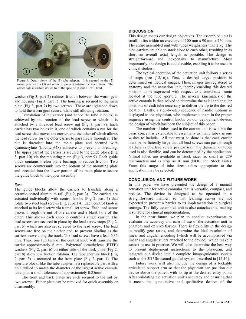
tube carriers. An exploded view of a carrier is shown in Fig. 3. Each carrier is responsible for actuating a single tube. The tubes are rigidly held by a tube adapter (Fig 3, part 4) to which the tube is affixed using cyanoacrylate (Loctite 648) adhesive which is rated to above 150° C (biocompatible and marketed for medical device use by Henkel, Inc.). The tube adapter fits over a brass worm gear (Fig 3, part 3) and is held in place by a set screw (Fig 4, part 3). As the control knob (Fig 3, part 5) is turned, it rotates a steel worm (Fig 3, part 6) in order to angularly position the tube about its axis. There is a 36:1 gear ratio between the worm and worm gear. Thus, one full turn of the control knob will rotate the tube ten degrees. A brass
Figure 2: Manual actuation unit consisting of (1) the front plate, (2) the tube aperture block, (3) the linear rail, (4) lead screws, (5) lead screw stops, (6) PTFE washers, (7) control knobs, and (8) the back plate.
Figure 3: Tube carrier mechanism. Exploded view with (1) rotational housing, (2) washer, (3) worm gear, (4) tube adapter, (5) control knob, (6) worm, (7) main plate, (8) lead screw nut, (9) mounting plate, and (10) linear guide block.
3 Copyright © 2011 by ASME
washer (Fig 3, part 2) reduces friction between the worm gear and housing (Fig 3, part 1). The housing is secured to the main plate (Fig 3, part 7) by two screws. These are tightened down to hold the worm gear secure, while still allowing rotation.
Translation of the carrier (and hence the tube it holds) is achieved by the rotation of the lead screw to which it is attached by a threaded lead screw nut (Fig 3, part 8). Each carrier has two holes in it, one of which contains a nut for the lead screw that moves the carrier, and the other of which allows the lead screw for the other carrier to pass freely through it. The nut is threaded into the main plate and secured with cyanoacrylate (Loctite 648) adhesive to prevent unthreading. The upper part of the carrier is secured to the guide block (Fig 3, part 10) via the mounting plate (Fig 3, part 9). Each guide block contains Frelon plane bearings to reduce friction. Two screws are countersunk into the bottom of the mounting plate and threaded into the lower portion of the main plate to secure the guide block to the upper assembly.
Base The guide blocks allow the carriers to translate along a ceramic-coated aluminum rail (Fig 2, part 3). The carriers are actuated individually with control knobs (Fig 2, part 7) that rotate two steel lead screws (Fig 2, part 4). Each control knob is attached to its lead screw via a small set screw. Each lead screw passes through the nut of one carrier and a blank hole of the other. This allows each knob to control a single carrier. The lead screws are secured in place by the lead screw stops (Fig 2, part 5) which are also set screwed to the lead screw. The lead screws are free on their other end, to prevent binding as the carriers move along the track. The lead screws have a lead 6.35 mm. Thus, one full turn of the control knob will translate the carrier approximately 6 mm. Polytetrafluoroethylene (PTFE) washers (Fig 2, part 6) on either side of the back plate (Fig 2, part 8) allow low friction rotation. The tube aperture block (Fig 2, part 2) is mounted to the front plate (Fig 2, part 1). The aperture block, like the tube adapter, is a replaceable part with a hole drilled to match the diameter of the largest active cannula tube, plus a small tolerance of approximately 0.25mm.
The front and back plates are each secured to the rail by two screws. Either plate can be removed for quick assembly or disassembly.
DISCUSSION This design meets our design objectives. The assembled unit is small; it fits within an envelope of 100 mm x 90 mm x 260 mm. The entire assembled unit with tubes weighs less than 2 kg. The tube carriers are able to stack close to each other, resulting in as short an overall axial length as possible. The design is straightforward and inexpensive to manufacture. Most importantly, the design is autoclavable, enabling it to be used in clinical studies.
The typical operation of the actuation unit follows a series of steps (see [15,16]). First, a desired target position is determined on medical images. Then, images are registered to anatomy and the actuation unit, thereby enabling this desired position to be expressed with respect to a coordinate frame located at the tube aperture. The inverse kinematics of the active cannula is then solved to determine the axial and angular positions of each tube necessary to deliver the tip to the desired location. Lastly, a step-by-step sequence of handle motions is displayed to the physician, who implements them in the proper sequence using the control knobs on our deployment device, the design of which has been the subject of this paper.
The number of tubes used in the current unit is two, but the basic concept is extendable to essentially as many tubes as one wishes to include. All that must be done is that each carrier must be sufficiently large that all lead screws can pass through it (there is one lead screw per carrier). The diameter of tubes used is also flexible, and can be determined by the application. Nitinol tubes are available in stock sizes as small as 279 micrometers and as large as 10 mm (NDC, Inc. Stock Lists). From this range of tube sizes, tubes appropriate to the application may be selected.
CONCLUSION AND FUTURE WORK In this paper we have presented the design of a manual actuation unit for active cannulas that is versatile, compact, and precise. The device is designed to be operated in a straightforward manner, so that learning curves are not expected to present a barrier to its implementation in surgical settings. The fully assembled unit is also autoclavable, making it suitable for clinical implementation.
In the near future, we plan to conduct experiments to evaluate the accuracy and ease of use of the actuation unit in phantom and ex vivo tissues. There is flexibility in the design to modify gear ratios, and determine the ideal resolution of linear and angular encoding (which will be accomplished via linear and angular rulers attached to the device), which make it easiest to use in practice. We will also determine the best way to present deployment instructions to the physician, and integrate our device into a complete image-guidance system such as the 3D Ultrasound-guided system described in [15,16].
Future work will also include the design of a lockable articulated support arm so that the physician can position our device above the patient with its tip at the desired entry point. After validating the actuation unit’s accuracy and ensuring that it meets the quantitative and qualitative desires of the
Figure 4: Detail views of the (1) tube adapter. It is secured to the (2) worm gear with a (3) set screw to prevent rotation between them. The center hole is custom drilled to fit the specific (4) tube it will hold.

4 Copyright © 2011 by ASME
physicians who will use it, we intend to conduct human trials to validate the effectiveness of the device in a clinical setting.
ACKNOWLEDGEMENTS This work was funded in part by award number 0651803
from the National Science Foundation, and in part award numbers R21 EB011628 and R44 CA134169 from the National Institutes of Health. The content is solely the responsibility of the authors and does not necessarily represent the official views of the National Science Foundation or the National Institutes of Health.
REFERENCES [1] Tobkes, A. I., and Nord, H. J., 1995, “Liver Biopsy:
Review of Methodology and Complications,” Digestive Diseases, 13, pp. 267-274.
[2] Wei, Z., Wan, G., and Gardi, L., 2004, “Robot-Assisted 3D-TRUS Guided Prostate Brachytherapy: System Integration and Validation,” Medical Physics, 31, pp. 539-548.
[3] Glozman, D., and Shoham, M., 2007, “Image-Guided Robotic Flexible Needle Steering,” IEEE Transactions on Robotics, 23(3), pp. 459-467.
[4] DiMaio, S. P., and Salcudean, S. E., 2003, “Needle Insertion Modeling and Simulation,” IEEE Transactions on Robotics and Automation, 19(5), pp. 864-875.
[5] Okazawa, S., Ebrahimi, R., Chuang, J., Salcudean, S. E., and Rohling, R., 2005, “Hand-Held Steerable Needle Device,” IEEE/ASME Transactions on Mechatronics, 10(3), pp. 285-296.
[6] Webster III, R. J., Cowan, N. J., Chirikjian, G. S., and Okamura, A. M., 2006, “Nonholonomic Modeling of Needle Steering,” International Journal of Robotics Research, 25(5/6), pp. 509-526.
[7] Kallem, V., and Cowan, N. J., 2009, “Image Guidance of Flexible Tip-Steerable Needles,” IEEE Transactions on Robotics, 25(1), pp. 191-196.
[8] S. Misra, K. B. Reed, B. W. Schafer, K. T. Ramesh, and A. M. Okamura. Mechanics of flexible needles
robotically steered through soft tissue. International Journal of Robotics Research, 2010, 29(13): 1640-1660, 2010.
[9] S. Misra, K. J. Macura, K. T. Ramesh, and A. M. Okamura. The Importance of Organ Geometry and Boundary Constraints for Planning of Medical Interventions, Medical Engineering & Physics, 31(2): 195-206, 2009.
[10] Webster III, R. J., Okamura, A. M., and Cowan, N. J., 2006 “Toward Active Cannulas: Miniature Snake-Like Surgical Robots,” IEEE/RSJ International Conference on Intelligent Robots and Systems, pp. 2857-2863.
[11] Webster III, R. J., Romano, J. M., and Cowan, N. J., “Mechanics of Precurved-Tube Continuum Robots,” 2009, IEEE Transactions on Robotics, 25(1), 67-78.
[12] D. C. Rucker, B. A. Jones, and R. J. Webster III. A Geometrically Exact Model for Externally Loaded Concentric Tube Continuum Robots. IEEE Transactions on Robotics, 26(5), 769-780, 2010.
[13] Sears, P., and Dupont, P., 2006, “A Steerable Needle Technology Using Curved Concentric Tubes,” IEEE/RSJ International Conference on Intelligent Robots and Systems, pp. 2850-2856.
[14] Dupont P, Lock J, Itkowitz B, Butler, E. "Design and Control of Concentric Tube Robots." IEEE Transactions on Robotics 2010; 26(2):209-225.
[15] E. C. Burdette, D. C. Rucker, P. Prakash, C. J. Diederich, J. M. Croom, C. Clarke, P. J. Stolka, T. Juang, E. M. Boctor, and R. J. Webster III. The ACUSITT Ultrasonic Ablator: The First Steerable Needle with an Integrated Interventional Tool. Proceedings of SPIE Medical Imaging, 2010.
[16] E. M. Boctor, P. Stolka, C. Clarke, D. C. Rucker, J. M. Croom, E. C. Burdette, and R. J. Webster III. Precisely Shaped Acoustic Ablation of Tumors Utilizing Steerable Needle and 3D Ultrasound Image Guidance. Proceedings of SPIE Medical Imaging, 2010.
Errata
T. L. Bruns, J. M. Tucker, D. Caleb Rucker, P. J. Swaney, E. M. Boctor, E. C. Burdette, J. Burgner, and R. J. Webster III. Design of an Autoclavable Active Cannula Deployment Device. Design of Medical Devices Conference, 2011. Dear Readers, The authors apologize for an error in this manuscript. We incorrectly say that Loctite 648 is a biocompatible adhesive. Instead, we direct the reader Loctite 4014. This adhesive explicitly states on its datasheet (http://tds.loctite.com/tds5/docs/4014-‐EN.PDF) that it can be autoclaved. With respect to biocompatibility, it has been tested by the manufacturer and meets ISO-‐10993 biocompatibility standards. Furthermore, perhaps the best option is to eliminate use of adhesive altogether. After publication of this conference paper we moved to a collet-‐like closure for this design, holding the tube with three setscrews evenly spaced around the hub. We also note that it is possible (and desirable where extreme compactness is not required) to use a true collet closure, replacing the hub with a collet. We have done this in: J. Das, D. C. Rucker, and R. J. Webster III. A Testbed for Multi-‐Lumen Steerable Needle Experiments. Design of Medical Devices Conference, 2010. using a custom-‐made collet, compressed with a set screw. We have also previously used ER-‐16 Spring collets, with a custom-‐designed closure. A photograph of such a device appears in figure 3.14 of: D. C. Rucker. The Mechanics of Continuum Robots: Model-‐Based Sensing and Control. Ph.D. Dissertation, Department of Mechanical Engineering, Vanderbilt University, Nashville, TN, December 2011. The one other use of the Loctite 648 in our paper is to hold the ACME nut into the main plate. We suggest eliminating the need for this adhesive by using a nut with a smooth external surface and press fitting it into the main plate. Lastly, this paper focused mainly on a design that could withstand autoclaving. We note that for biocompatibility, before human use, we intend to anodize all aluminum components, passivate stainless steel components, and eliminate bronze components in favor of plastics such as Ultem. It is unclear whether all these changes are strictly necessary, since many components will always be relatively far from the patient, but we plan to implement them in any case, to be on the safe side. Sincerely, The Authors