Design of a Rainwater Collection System for Irrigation ...
55
Trinity University Trinity University Digital Commons @ Trinity Digital Commons @ Trinity Engineering Senior Design Reports Engineering Science Department 2008 Design of a Rainwater Collection System for Irrigation Purposes Design of a Rainwater Collection System for Irrigation Purposes Philip Gates Trinity University Libby Gravatt Trinity University Tyler Mellos Trinity University Alex Miller Trinity University Dario Turjanski Trinity University Follow this and additional works at: https://digitalcommons.trinity.edu/engine_designreports Repository Citation Repository Citation Gates, Philip; Gravatt, Libby; Mellos, Tyler; Miller, Alex; and Turjanski, Dario, "Design of a Rainwater Collection System for Irrigation Purposes" (2008). Engineering Senior Design Reports. 16. https://digitalcommons.trinity.edu/engine_designreports/16 This Restricted Campus Only is brought to you for free and open access by the Engineering Science Department at Digital Commons @ Trinity. It has been accepted for inclusion in Engineering Senior Design Reports by an authorized administrator of Digital Commons @ Trinity. For more information, please contact [email protected].
Transcript of Design of a Rainwater Collection System for Irrigation ...
Trinity University Trinity University
Digital Commons @ Trinity Digital Commons @ Trinity
Engineering Senior Design Reports Engineering Science Department
2008
Design of a Rainwater Collection System for Irrigation Purposes Design of a Rainwater Collection System for Irrigation Purposes
Philip Gates Trinity University
Libby Gravatt Trinity University
Tyler Mellos Trinity University
Alex Miller Trinity University
Dario Turjanski Trinity University
Follow this and additional works at: https://digitalcommons.trinity.edu/engine_designreports
Repository Citation Repository Citation Gates, Philip; Gravatt, Libby; Mellos, Tyler; Miller, Alex; and Turjanski, Dario, "Design of a Rainwater Collection System for Irrigation Purposes" (2008). Engineering Senior Design Reports. 16. https://digitalcommons.trinity.edu/engine_designreports/16
This Restricted Campus Only is brought to you for free and open access by the Engineering Science Department at Digital Commons @ Trinity. It has been accepted for inclusion in Engineering Senior Design Reports by an authorized administrator of Digital Commons @ Trinity. For more information, please contact [email protected].
Senior Design – ENGR4382
Design of a Rainwater Collection System for Irrigation Purposes
Philip Gates, Libby Gravatt, Tyler Mellos, Alex Miller, Dario Turjanski
Dr. Alexander, Advisor
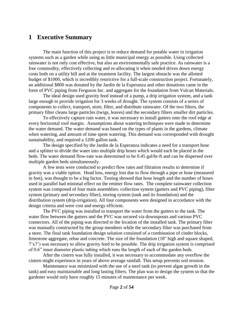
A rainwater collection system implemented in a small community garden in San Antonio
proposes to operate as efficiently as possible. The original design problem and proposed solution
are discussed, and the construction process and the final design are evaluated. A set of
experiments was conducted to help determine specific building parameters that would be
included in the final design. Once built, the system successfully completed the major goal, to
distribute water through a garden plot, by employing each of the other system components. The
drip hoses, on average, flowed at 0.64 GPH/ft which is higher than our minimum of 0.45 GPH/ft.
However, this was at a water height of 36” from the ground. The complete stepwise process
taken to construct such a system is outlined below, and includes recommendations for future
work or similar systems. With the goals of renewability, sustainability, and conservation in mind,
a simple and intelligent design could eventually become a common structure in residential and
commercial buildings.
Page 2 of 54
1 Executive Summary
The main function of this project is to reduce demand for potable water in irrigation
systems such as a garden while using as little municipal energy as possible. Using collected
rainwater is not only cost effective, but also an environmentally safe practice. As rainwater is a
free commodity, effectively collecting and re-allocating it when needed drives down energy
costs both on a utility bill and at the treatment facility. The largest obstacle was the allotted
budget of $1000, which is incredibly restrictive for a full-scale construction project. Fortunately,
an additional $800 was donated by the Jardin de la Esperanza and other donations came in the
form of PVC piping from Ferguson Inc. and aggregate for the foundation from Vulcan Materials.
The ideal design used gravity feed instead of a pump, a drip irrigation system, and a tank
large enough to provide irrigation for 3 weeks of drought. The system consists of a series of
components to collect, transport, store, filter, and distribute rainwater. Of the two filters, the
primary filter cleans large particles (twigs, leaves) and the secondary filters smaller dirt particles.
To effectively capture rain water, it was necessary to install gutters onto the roof edge at
every horizontal roof margin. Assumptions about watering techniques were made to determine
the water demand. The water demand was based on the types of plants in the gardens, climate
when watering, and amount of time spent watering. This demand was corresponded with drought
sustainability, and required a 1200 gallon tank.
The design specified by the Jardin de la Esperanza indicates a need for a transport hose
and a splitter to divide the water into multiple drip hoses which would each be placed in the
beds. The water demand flow-rate was determined to be 0.45 gal/hr-ft and can be dispersed over
multiple garden beds simultaneously.
A few tests were conducted to predict flow rates and filtration results to determine if
gravity was a viable option. Head loss, energy lost due to flow through a pipe or hose (measured
in feet), was thought to be a big factor. Testing showed that hose length and the number of hoses
used in parallel had minimal effect on the emitter flow rates. The complete rainwater collection
system was composed of four main assemblies: collection system (gutters and PVC piping), filter
system (primary and secondary filter), storing system (tank and its foundation) and the
distribution system (drip-irrigation). All four components were designed in accordance with the
design criteria and were cost and energy efficient.
The PVC piping was installed to transport the water from the gutters to the tank. The
water flow between the gutters and the PVC was secured via downspouts and various PVC
connectors. All of the piping was directed to the location of the installed tank. The primary filter
was manually constructed by the group members while the secondary filter was purchased from
a store. The final tank foundation design solution consisted of a combination of cinder blocks,
limestone aggregate, rebar and concrete. The size of the foundation (18" high and square shaped,
7’x7’) was necessary to allow gravity feed to be possible. The drip irrigation system is comprised
of 0.6” inner diameter plastic tubing which runs the length of each of the garden beds.
After the cistern was fully installed, it was necessary to accommodate any overflow the
cistern might experience in years of above average rainfall. This setup prevents soil erosion.
Maintenance was minimized with the use of a steel tank (to prevent algae growth in the
tank) and easy maintainable and long lasting filters. The plan was to design the system so that the
gardener would only have roughly 15 minutes of maintenance per week.
Page 3 of 54
2 Table of Contents
1 Executive Summary ........................................................................................................................................... 2
2 Table of Contents ............................................................................................................................................... 3
3 Table of Figures .................................................................................................................................................. 5
4 Table of Tables ................................................................................................................................................... 5
5 Introduction ........................................................................................................................................................ 6
6 Design Overview ................................................................................................................................................. 6
7 Alternatives ......................................................................................................................................................... 8
7.1 Filters ............................................................................................................................................................ 11
7.2 Storage .......................................................................................................................................................... 13
7.3 Distribution ................................................................................................................................................... 17
8 Prototype Test Plan .......................................................................................................................................... 19
8.1 Experimentation ............................................................................................................................................ 20
8.2 Prototype Testing Results .............................................................................................................................. 22
9 Final System Design and Construction .......................................................................................................... 24
9.1 Collection System .......................................................................................................................................... 24
9.2 Filtration System ........................................................................................................................................... 26
9.3 Tank and Foundation Installation ................................................................................................................... 2
9.4 Distribution System ......................................................................................................................................... 6
10 Analyzing the Design ....................................................................................................................................... 10
10.1 Satisfaction of Criterion ........................................................................................................................... 10
10.2 Effectiveness of the System ....................................................................................................................... 13
10.3 Problems Encountered ............................................................................................................................. 13
10.4 Maintenance and Upkeep ......................................................................................................................... 14
Page 4 of 54
11 Conclusions and Recommendations ............................................................................................................... 14
12 References ......................................................................................................................................................... 17
A Drip Irrigation Testing Data ............................................................................................................................. 1
Table A-2. Drip Irrigation Testing, Flow Rates for 4GPH Emitters ....................................................................... 2
B Maintenance Manual ......................................................................................................................................... 3
C Final Budget ....................................................................................................................................................... 1
D Bill of Materials .................................................................................................................................................. 2

Page 5 of 54
3 Table of Figures
FIGURE 1. CAD DRAWING OF FILTER, INLET, STORAGE TANK, OUTLET, AND DISTRIBUTION METHOD .......................... 11
FIGURE 2. SELF-CLEANING FILTER FOR TREE LITTER AND SIMILARLY SIZED PARTICULATES ........................................ 12
FIGURE 3. PROPOSED DESIGN FOR LARGE PARTICULATE FILTER ................................................................................... 12
FIGURE 4. CATCHMENT SURFACE AT JE TOTALING 1152 FT2 ........................................................................................ 14
FIGURE 5. PLAN OF JE .................................................................................................................................................. 17
FIGURE 6. GARDEN BEDS AT JE, NAMES AND LOCATIONS ........................................................................................... 18
FIGURE 7. BUCKET-PIPE CONNECTION .......................................................................................................................... 20
FIGURE 8. HOSE STAND ................................................................................................................................................ 21
FIGURE 9. DRIP IRRIGATION TESTING SETUP ................................................................................................................. 22
FIGURE 10. VARIANCE IN FLOW RATE BY EMITTER SIZE (WATER LEVEL GROUPING) .................................................... 23
FIGURE 11. VARIANCE IN FLOW RATE BY WATER LEVEL (EMITTER SIZE GROUPING) .................................................... 23
FIGURE 12. GUTTER AND HOSE PLACEMENT ALONG THE CATCHMENT SURFACE (BUILDING ROOF) .............................. 25
FIGURE 13. PRIMARY FILTER DESIGN ............................................................................................................................ 27
FIGURE 14. PRIMARY FILTER AFTER CONSTRUCTION .................................................................................................... 28
FIGURE 15. RAINWATER COLLECTION SYSTEM PLANS, JE ........................................................................................... 29
FIGURE 16. PRIMARY FILTER INSTALLED AT TANK INLET ............................................................................................... 1
FIGURE 17. TOP VIEW OF TANK FOUNDATION DESIGN; NOTE: FIGURE NOT DRAWN TO SCALE ........................................ 3
FIGURE 18. SIDE VIEW OF TANK FOUNDATION DESIGN; NOTE: FIGURE NOT DRAWN TO SCALE ....................................... 4
FIGURE 19. OVERFLOW PIPE, NEXT TO PRIMARY FILTER, IN FINAL SYSTEM. ................................................................... 5
FIGURE 20. FINAL LAYOUT OF DRIP HOSES IN BEDS. ....................................................................................................... 7
FIGURE 21. COMPARISON OF FINAL DESIGN TESTING WITH LABORATORY TESTING ........................................................ 9
FIGURE 22. LAYOUT OF TRANSPORT HOSE AND VALVES WITH TANK. ........................................................................... 12
4 Table of Tables
TABLE 1. ANNUAL WATER BALANCE FOR A TYPICAL YEAR .......................................................................................... 7
TABLE 2. ALTERNATIVE SYSTEMS.................................................................................................................................. 9
TABLE 3. ALTERNATIVES MATRIX AND DESIGN CRITERIA WEIGHTING ......................................................................... 9
TABLE 4. AVAILABLE RAINWATER FOR COLLECTION IN SAN ANTONIO ....................................................................... 13
TABLE 5. BED WATERING: TIME, DEMAND AND FLOW RATE ...................................................................................... 18
TABLE 6. VARIOUS WATERING PLANS WITH CORRESPONDING WATERING TIMES AND FLOW RATES .......................... 19
TABLE 7. FINAL DESIGN FLOW RATE TESTING RESULTS, 36” HEAD ................................................................................. 8
Page 6 of 54
5 Introduction
As the global population continues to grow and advance, more and more strain is being placed
on natural resources. Fortunately, there is also growing awareness concerning renewable energy
and resources. One such topic of discussion is water conservation. Many households are using
low flow toilets and showers, and alternative water sources are being discussed. The primary
goal is to design and build a small rainwater collection system in San Antonio that will collect
rain, transport it to a storage tank, filter out medium and large particulates, and distribute the
stored water on site to a small garden plot while remaining as energy efficient as possible. As
such, this paper will detail the process behind implementing such a system from start to finish, as
well as recommend any improvements that can be made. It should also serve as a reference for
individuals interested in installing similar systems for residential irrigation purposes.
The main function of this project is to reduce demand for potable water in irrigation systems
such as a garden while using as little municipal energy as possible. The overall objective is to
implement a system at el Jardin de la Esperanza (JE) that will collect and transport rainwater
from an asphalt shingle roof to an onsite storage cistern while filtering out large particles and
then deliver the collected water to the existing garden plot. The system is to be low maintenance,
requiring no more than 30 minutes per week for upkeep. Furthermore, the system will be reliable
and most importantly, the system will effectively meet the water demands of the garden and the
plants it contains, and provide enough water to cover a drought period of three weeks.
6 Design Overview
As mentioned previously, the main goal of this project is to reduce demand for potable water in
irrigation systems. Using collected rainwater is not only cost effective, but also environmentally
safe practice. As rainwater is a free commodity, effectively collecting and re-allocating it when
needed drives down energy costs both on a utility bill and at the treatment facility. As such,
gravity feed was proposed to water the garden instead of implementing a pump to supply the
needed water pressure to the drip hoses. In order to determine if gravity feed was a viable option,
sample calculations and prototype tests were conducted. Once the necessary data had been

Page 7 of 54
collected and analyzed, it was determined that the storage tank would need to be raised 18 inches
above ground to build the necessary pressure. This discovery led to an analysis of the ground soil
in San Antonio, which demonstrated that an appropriate foundation was needed. The
construction specifications will be discussed in later sections. Another goal is to effectively meet
the water demands of the garden, which ultimately led to the determination of the tank volume.
Using information gathered from JE and their watering schedule, as well as annual average
precipitation data, a water demand table was developed assuming that the year begins with a full
tank (Table 1).
Table 1. Annual Water Balance for a Typical Year
Month
Avg days
per mo.
w/o rain
Evaporation
Rate
Growing
days/mo.
Water
Demand
(gal)
Rainfall
Collected
(gal)
Balance
(gal) Overflow
(gal)
Jan 23.3 Low 0% 0 1,076 1,200 1,076
Feb 20.0 Low 100% 775 1,299 1,200 524
Mar 20.0 Typical 100% 1,550 1,123 773 0
Apr 22.1 Typical 100% 1,717 1,705 761 0
May 22.0 Typical 100% 1,705 2,686 1,200 541
Jun 22.8 High 50% 1,470 2,442 1,200 973
Jul 22.6 High 0% 0 1,231 1,200 1,231
Aug 25.0 High 0% 0 1,658 1,200 1,658
Sep 22.5 High 100% 2,907 2,084 377 0
Oct 21.1 Typical 100% 1,638 2,314 1,053 0
Nov 21.7 Low 100% 842 1,515 1,200 527
Dec 23.0 Low 50% 446 1,143 1,200 550
Total 13,049 20,276 7,079
With these goals in mind, constraints were also considered and evaluated. The largest obstacle
was the allotted budget of $1000, which is incredibly restrictive for a full scale construction
project such as the one described. Fortunately, an additional $800 in funding was donated by JE,
as they had made room in their budget to complete a rain harvesting project. Additionally, the
team received generous material donations from Vulcan Materials, who supplied the aggregate

Page 8 of 54
for the foundation, and Ferguson Inc., who supplied the PVC piping necessary to transport the
collected water to the tank. Another constraint is time. Finding the site to implement this system
took much longer than anticipated, and building could not commence until appropriate tests and
calculations had been completed. Lastly, the system needs to be fully operational by the end of
April 2008.
One of the byproducts of the financial situation was the size of the tank that could be purchased.
Although a 2,400 gallon tank would have collected more water and allowed the system to sustain
a garden through a longer drought period of 6 weeks, the budget would not allow for such a tank.
Instead, a compromise was made to ensure that the system would sustain the garden for up to 3.2
weeks of drought by installing a 1200 gallon tank.
7 Alternatives
To determine which alternative best met the criteria outlined in Memo 1: Project Descriptions
and Specifications, the following tables were developed. Table 2 describes the alternatives and
their components. Table 3 shows the ratings for how each alternative fulfills the criteria. The
ratings were developed based upon the considerations of which combinations of the system
components suit the “ideal” design the best. The “ideal” design would implement a system which
would use the least possible energy, would be most cost efficient, offer sufficient filtration and
provide irrigation for at least 6 weeks of drought. Each rating is multiplied by its weight and
summed with the other ratings for each alternative. This produces a final score for each
alternative, a percentage rating of how well the alternative meets the design criteria.

Page 9 of 54
Table 2. Alternative Systems
System Component Alternative 1 Alternative 2 Alternative 3 Alternative 4
Catchment Surface Parking lot Pond Elevated
impervious cover Roof
Water Transportation
(Surface to Storage)
Natural slope of land +
barriers
Natural slope
of land
Gutters + PVC
piping Gutters + PVC piping
Storage In-ground cistern Pond Tank on ground Tank on raised
mound
Filtration Screen filter + first flush
diverter + settling in tank
Mesh + sand
filter
Gravel + sand
filter Gutter Filter
Energy Source Bicycle w/ pump Grid + pump Solar + battery for
pump Gravity
Distribution Drip irrigation Sprinkler
system Mist irrigation
Solar-powered valve
for drip irrigation
Table 3. Alternatives Matrix and Design Criteria Weighting
Design Criteria Weighting Alternative 1 Alternative 2 Alternative 3 Alternative 4
Ease of Maintenance &
User Friendliness 15% 5 7 5 9
Water Purity 25% 7 8 9 8
Water Supply
(Quantity & Delivery) 30% 10 8 4 8
Cost 15% 3 7 4 5
Energy Demand 12% 10 1 10 10
Aesthetics 3% 8 9 3 8
Total Score 100% 74% 69% 61% 79%
Based upon the scores in Table 3, it was decided that the best system is the last choice,
alternative four. Using a roof makes the system versatile and easy to implement in the home or in
a commercial setting. Additionally, it satisfies the design criteria originally outlined by
remaining cost effective, low maintenance and as energy efficient as possible (meaning using the
least amount of electrical energy as possible to run the system, if any at all). Furthermore, the
overall system is a fairly simple design, which translates to ease of manufacture.
Page 10 of 54
Although alternative four was chosen, not all of its prescribed system components were utilized.
Due to the strong desire of JE employees for hands on gardening, the original plan of using a
solar powered water timer system was not desired. Instead, the gardeners will just turn the valve
at the outlet of the tank to start and conclude the daily or bi-daily watering of the plants. Also,
the pre-tank filtering system in alternative four, GutterFilter, was not used, but was rather
replaced with a more comprehensive filtration system. All of the other components remained the
same.
The system consists of a series of components to collect, transport, store, filter, and distribute
rainwater. The first system component at JE, the catchment surface, is a shingled roof. The
catchment surface had no means of collecting rainwater and thus, gutters were purchased and
installed. The roof of the house beside the garden plot at JE provides a surface area of 1152 ft2
and the gutters are sized accordingly. From the gutter system, the water enters the downspout
system and just before reaching the tank’s inlet, the water will pass through a self-cleaning
screen filter in order to remove large particles. A central component in the design is the above
ground storage container; not only is it the most expensive component ($800), it is also the
largest and most visually obvious piece of the system. The tank has an overflow pipe, which will
allow excess water to escape if the tank has reached its maximum capacity (1200 gallons). A
secondary filter is placed at the tank outlet to catch any remaining particles which were smaller
than the mesh openings in the first filter. This secondary mesh ensures that particles small
enough to clog the emitters, after exiting the tank, do not enter the hose line. An outlet spout at
the bottom of the tank connects the tank to the distribution system.
The outlet valve is opened to flood the distribution system with the collected rainwater. The
height of water standing in the tank will create 1 psi for each 2.31 feet of water depth, providing
the pressure needed to distribute water to all the garden beds. The outlet valve connects to a
splitter via a transport hose to divide the flow into multiple lines for drip irrigation. These drip
lines are fitted with emitters to distribute the water throughout the garden plot.
Page 11 of 54
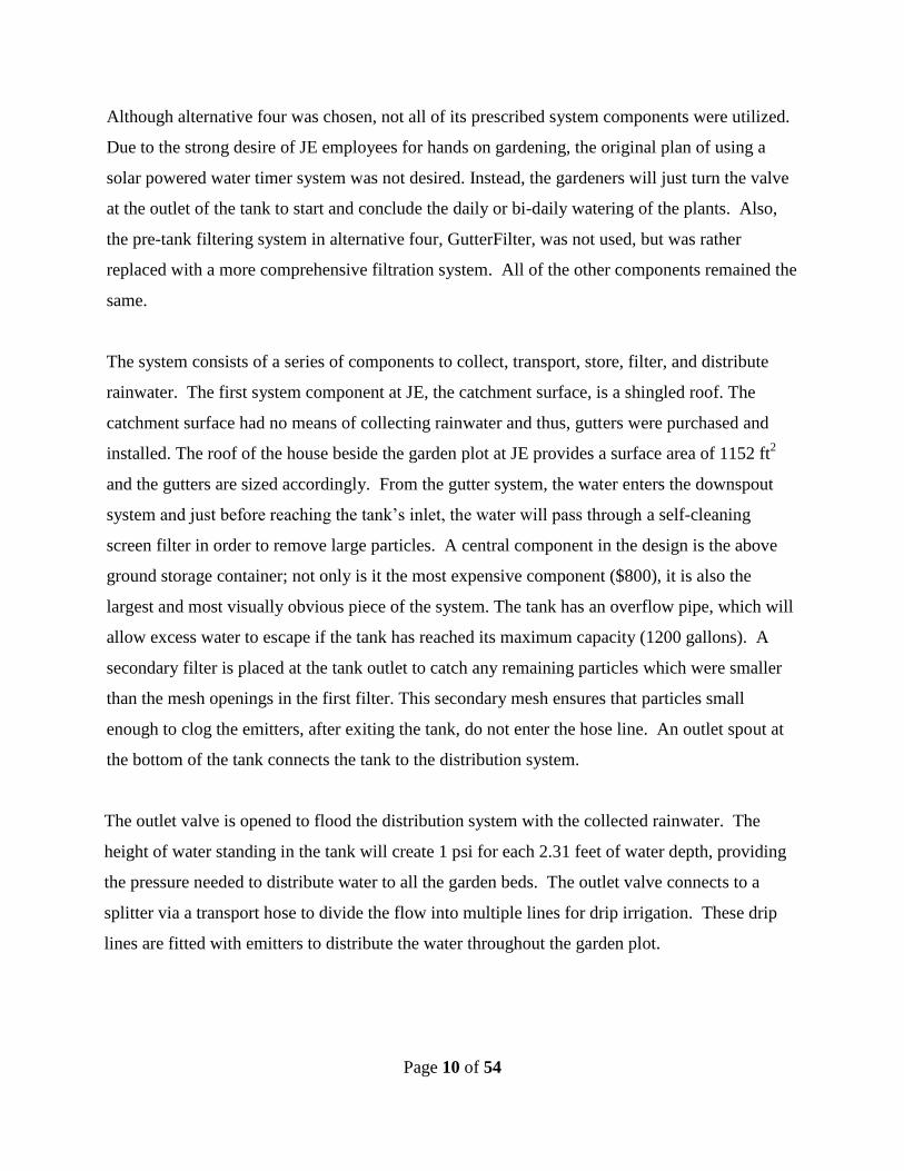
Figure 1. CAD drawing of filter, inlet, storage tank, outlet, and distribution method
In Fig. 1, the blue inlet pipe is attached to the downspouts on the building and is the pipe which
brings the water from the catchment surface into the storage tank. This inlet flows into the green
filter system, which is comprised of a mesh screen in between two pieces of PVC. The location
of the first mesh is shown in this assembly and will be detailed later in this section.
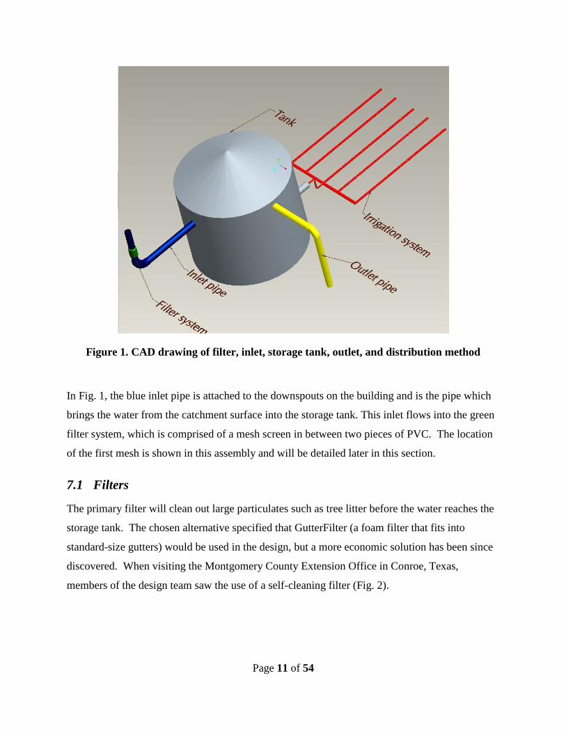
7.1 Filters
The primary filter will clean out large particulates such as tree litter before the water reaches the
storage tank. The chosen alternative specified that GutterFilter (a foam filter that fits into
standard-size gutters) would be used in the design, but a more economic solution has been since
discovered. When visiting the Montgomery County Extension Office in Conroe, Texas,
members of the design team saw the use of a self-cleaning filter (Fig. 2).
Page 12 of 54
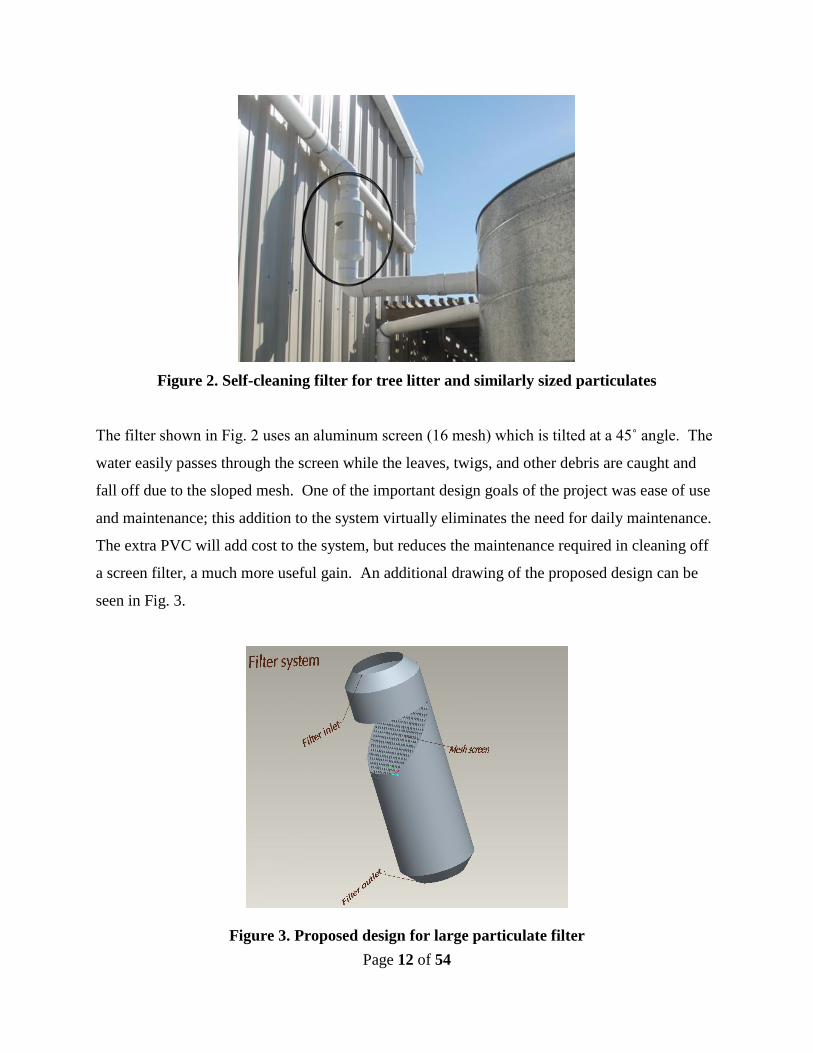
Figure 2. Self-cleaning filter for tree litter and similarly sized particulates
The filter shown in Fig. 2 uses an aluminum screen (16 mesh) which is tilted at a 45˚ angle. The
water easily passes through the screen while the leaves, twigs, and other debris are caught and
fall off due to the sloped mesh. One of the important design goals of the project was ease of use
and maintenance; this addition to the system virtually eliminates the need for daily maintenance.
The extra PVC will add cost to the system, but reduces the maintenance required in cleaning off
a screen filter, a much more useful gain. An additional drawing of the proposed design can be
seen in Fig. 3.
Figure 3. Proposed design for large particulate filter
Page 13 of 54
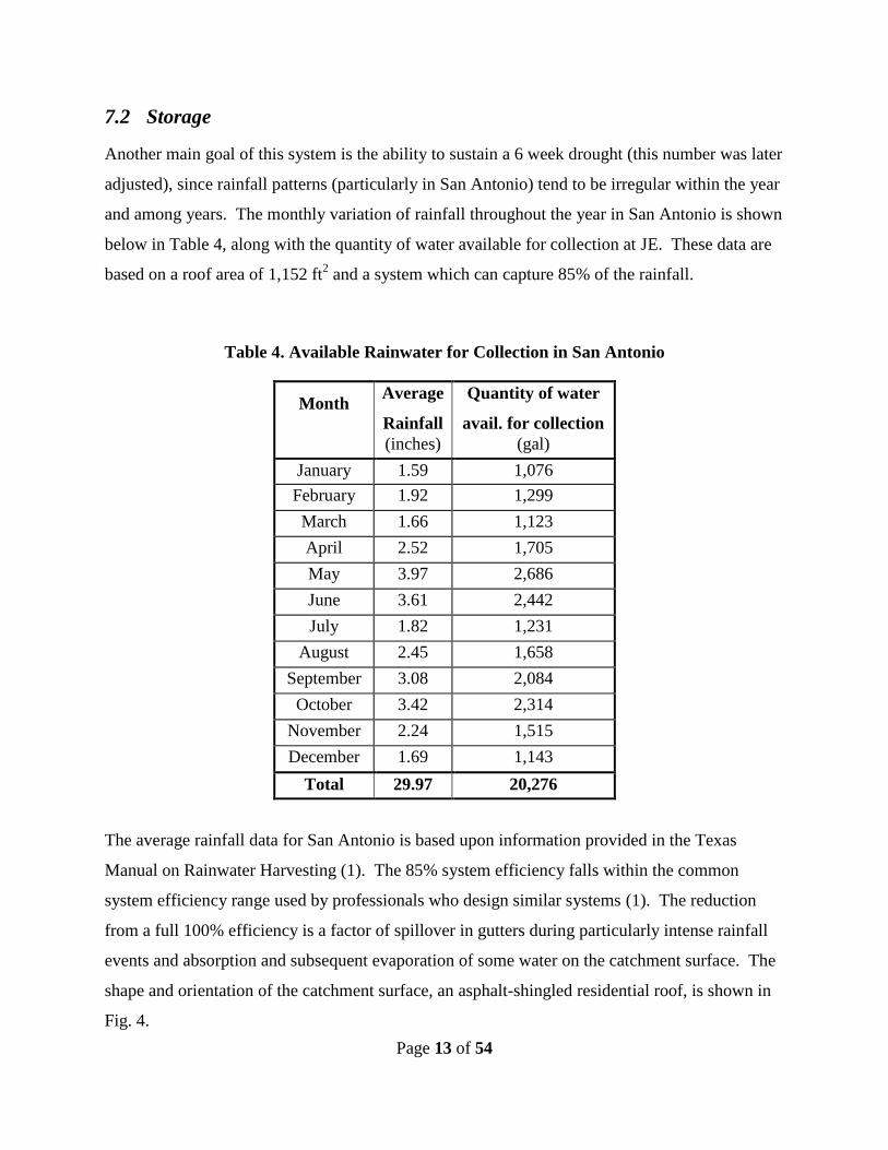
7.2 Storage
Another main goal of this system is the ability to sustain a 6 week drought (this number was later
adjusted), since rainfall patterns (particularly in San Antonio) tend to be irregular within the year
and among years. The monthly variation of rainfall throughout the year in San Antonio is shown
below in Table 4, along with the quantity of water available for collection at JE. These data are
based on a roof area of 1,152 ft2 and a system which can capture 85% of the rainfall.
Table 4. Available Rainwater for Collection in San Antonio
Month Average
Rainfall
Quantity of water
avail. for collection
(inches) (gal)
January 1.59 1,076
February 1.92 1,299
March 1.66 1,123
April 2.52 1,705
May 3.97 2,686
June 3.61 2,442
July 1.82 1,231
August 2.45 1,658
September 3.08 2,084
October 3.42 2,314
November 2.24 1,515
December 1.69 1,143
Total 29.97 20,276
The average rainfall data for San Antonio is based upon information provided in the Texas
Manual on Rainwater Harvesting (1). The 85% system efficiency falls within the common
system efficiency range used by professionals who design similar systems (1). The reduction
from a full 100% efficiency is a factor of spillover in gutters during particularly intense rainfall
events and absorption and subsequent evaporation of some water on the catchment surface. The
shape and orientation of the catchment surface, an asphalt-shingled residential roof, is shown in
Fig. 4.

Page 14 of 54
Figure 4. Catchment surface at JE totaling 1152 ft2
To effectively capture the quantities of water shown in Table 4 above, it was necessary to install
gutters onto the roof edge at every horizontal roof margin. Considering how the system may best
meet the water demands of JE, it is preferable to capture rainfall from the entire roof so as to
have the maximum quantity of water available in dry years. In order to determine if a rainwater
collection system based around this collection surface could meet the water demand of the
garden on a yearly basis, a water balance was drawn up for a typical year (Table 1).
In this predictive balance, assumptions about watering techniques were made to determine the
water demand. Through a discussion with Angela Hartsell, the Community Gardens Project
Manager at Bexar Land Trust (the organization which sponsors JE), the following seasonal
growing patterns were determined: the warm and cool growing seasons begin in February and
September, respectively, when seedlings are planted. The plants mature and their growing
seasons continue throughout the rest of the year, except for the months when the weather is
typically too hot or cold. During the hot months, the latter half of June and all of July and
August, and the cold months, the latter half of December and all of January, there will be no
plants so no watering is necessary. Furthermore, during the hot months any surviving plants
require increased watering because of increased water evaporation (from the soil) and
42’
32’
16’
8’

Page 15 of 54
evapotranspiration (from the plants) rates; likewise, the cool months require less frequent
watering. According to The Agriculture Program of the Texas A&M University System (2),
closely spaced vegetables (less than two feet between plants), like those at JE, in medium
coarseness soil, like that of its garden beds, thrive best with watering from a drip irrigation
system with the following characteristics: one drip hose per row of vegetables, one emitter every
20” of hose, 0.75 gallons per hour flow rate for each emitter, and 2 hours of watering per
irrigation event. The agriculture program suggests that weekly irrigation times with this setup
should total to 3 hours during cool weather, 6 hours during warm weather, and 10 hours during
hot weather. As one would expect, however, the plot is watered only on days for which there is
no rain. Thus, these weekly watering times were applied across the total number of days per
month without rain. The data pertaining to average days per month without rain represent a
monthly average taken from eight years (2000 through 2007) of actual daily rainfall data. The
total number of days of rain in a month is subtracted from the number of days in the month to
give the final value. This daily rainfall data is from the local airport records, accessed through
the Weather Underground website (3).
The above calculations for water demand assume a plot area of 414ft2
(see Fig. 5), with the rows
spaced two feet apart within each bed. Thus, based upon the row spacing, row lengths, the
number of days per month without rainfall, and the agriculture program’s suggested watering
schedule for a garden like JE, the total water demand per month was calculated. This watering
program will replace the current one developed by Angela Hartsell in which 1.5” of city potable
water are supplied to the entire plot via a spray nozzle and hose. Both these methods are verified
by the vegetable water demand information provided by The Agriculture Program of the Texas
A&M University System (2):
In sandy loam soils, broccoli, cabbage, celery, sweet corn, lettuce, potatoes and radishes
have most of their roots in the top 6 to 12 inches of soil (even though some roots go down 2 feet)
and require frequent irrigation of about 3/4 to 1 inch of water. Vegetables which have most of their
root systems in the top 18 inches of soil including beans, beets, carrots, cucumbers, muskmelons,
peppers and summer squash. These vegetables withdraw water from the top foot of soil as they
approach maturity and can profit from 1 to 2 inches of water per irrigation.
Page 16 of 54
A few vegetables, including the tomato, cantaloupe, watermelon and okra, root deeper.
As these plants grow they profit from irrigations of up to 2 inches of water.
Next, the water balance (quantity of water in the tank at the end of each month) assumes a 1,200
gallon tank which is entirely full at the start of a given year (January). The balance is calculated
as the volume of water in the tank from previous months, plus the rainfall collected in the current
month, minus the month’s water demand. Any balance over 1,200 gallons leaves the tank as
overflow. As this analysis is performed based on data available for typical yearly San Antonio
weather, the fact that there is an overflow of 4,350 gallons and that the tank is never quite empty
suggests that the system will be able to meet full yearly demand and sustain the garden
temporarily during years larger than average dry spells. The projected goal of sustaining a water
supply for 6 weeks of drought with no rain, however, is not achievable with the limited funding
for this project. The average weekly demand for the garden plot is 394 gallons, thus a full tank
with a capacity of 2,400 gallons would be required to meet a six week drought. The projected
1,200 gallon tank could sustain a drought of 3.2 weeks. Thus the system is expected to meet the
full water demand on a typical year in San Antonio; however, the system would have to be
supplemented with city water to sustain the garden, as is, through an extended drought in a year
when all garden beds were planted throughout all described growing seasons. Another approach
to extending the time period for which the system can sustain the garden would be to reduce the
water demand. Mulching and covering beds with shade-cloth are two examples of demand-
reducing measures. A final solution for extending the system’s watering capacity during periods
of drought should be decided in collaboration with the gardeners who will perform the irrigation.
Page 17 of 54
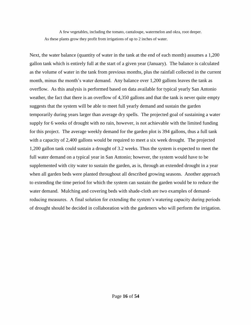
Figure 5. Plan of JE
7.3 Distribution
With the final plot location being JE, it is ideal to replicate their desired distribution system. As
shown in Fig. 5, the garden will consist of several raised beds containing vegetables, which have
a high water demand. The design specified by JE indicates a need for a transport hose and a
splitter to divide the water into multiple drip hoses which would each be placed in the beds. A
water demand and flow rate estimation was developed for each bed, and can be seen below in
Table 5.
Page 18 of 54
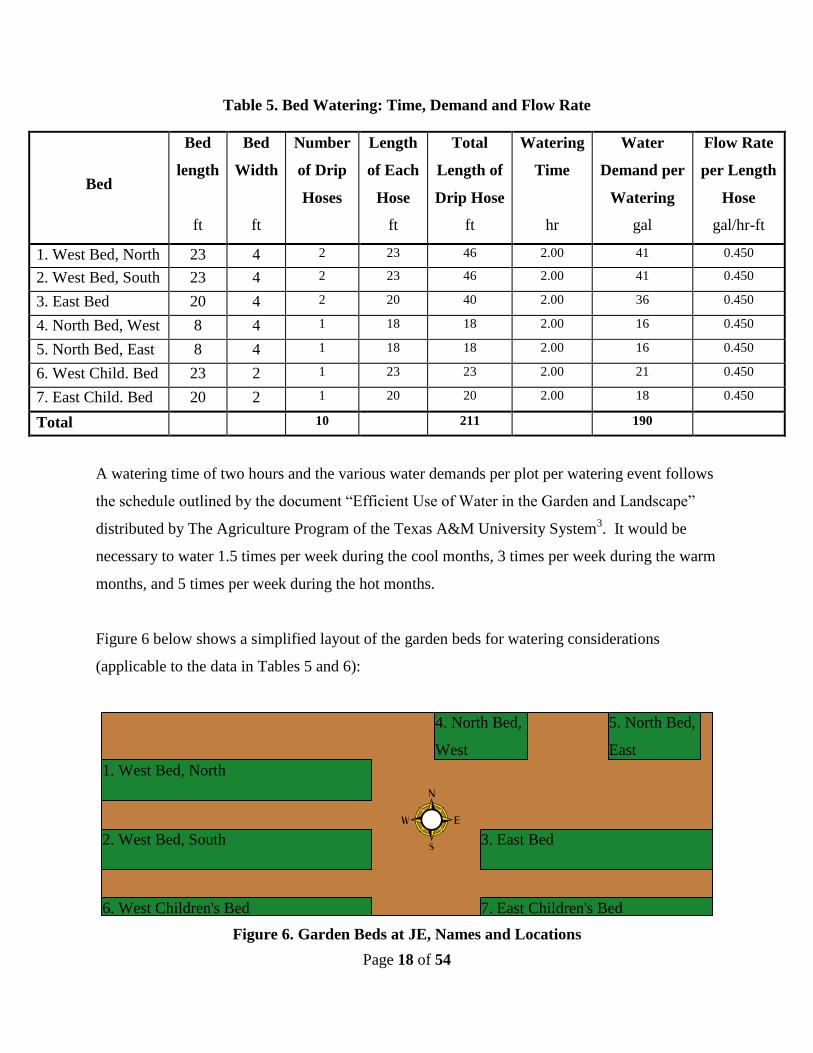
Table 5. Bed Watering: Time, Demand and Flow Rate
Bed
Bed
length
ft
Bed
Width
ft
Number
of Drip
Hoses
Length
of Each
Hose
ft
Total
Length of
Drip Hose
ft
Watering
Time
hr
Water
Demand per
Watering
gal
Flow Rate
per Length
Hose
gal/hr-ft
1. West Bed, North 23 4 2 23 46 2.00 41 0.450
2. West Bed, South 23 4 2 23 46 2.00 41 0.450
3. East Bed 20 4 2 20 40 2.00 36 0.450
4. North Bed, West 8 4 1 18 18 2.00 16 0.450
5. North Bed, East 8 4 1 18 18 2.00 16 0.450
6. West Child. Bed 23 2 1 23 23 2.00 21 0.450
7. East Child. Bed 20 2 1 20 20 2.00 18 0.450
Total 10 211 190
A watering time of two hours and the various water demands per plot per watering event follows
the schedule outlined by the document “Efficient Use of Water in the Garden and Landscape”
distributed by The Agriculture Program of the Texas A&M University System3. It would be
necessary to water 1.5 times per week during the cool months, 3 times per week during the warm
months, and 5 times per week during the hot months.
Figure 6 below shows a simplified layout of the garden beds for watering considerations
(applicable to the data in Tables 5 and 6):
Figure 6. Garden Beds at JE, Names and Locations
6. West Children's Bed 7. East Children's Bed
2. West Bed, South
1. West Bed, North
3. East Bed
4. North Bed,
West
5. North Bed,
East
Page 19 of 54
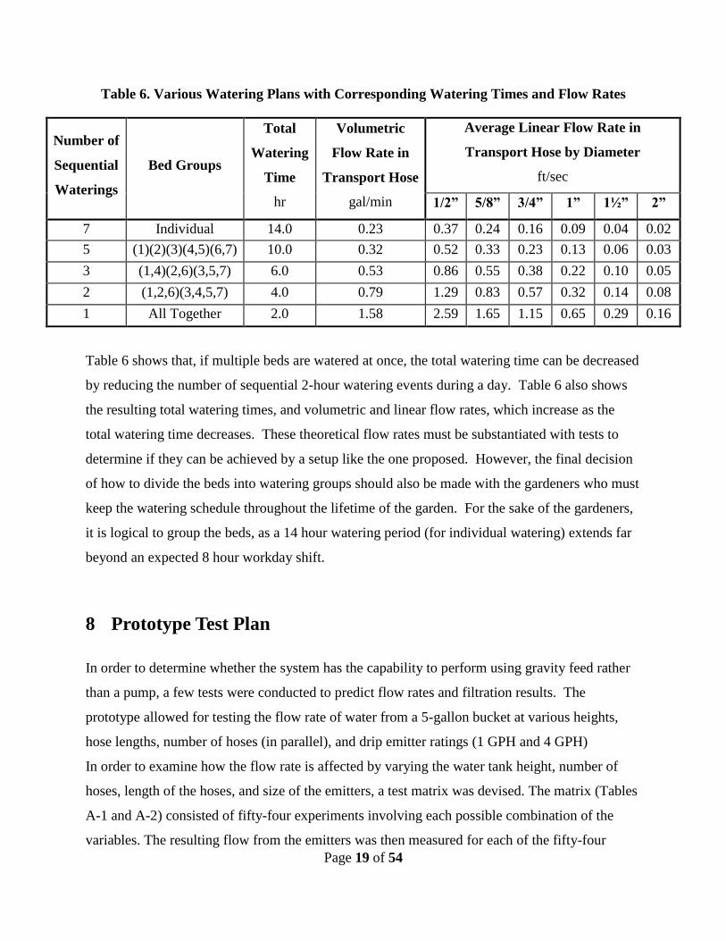
Table 6. Various Watering Plans with Corresponding Watering Times and Flow Rates
Number of
Sequential
Waterings
Bed Groups
Total
Watering
Time
hr
Volumetric
Flow Rate in
Transport Hose
gal/min
Average Linear Flow Rate in
Transport Hose by Diameter
ft/sec
1/2” 5/8” 3/4” 1” 1½” 2”
7 Individual 14.0 0.23 0.37 0.24 0.16 0.09 0.04 0.02
5 (1)(2)(3)(4,5)(6,7) 10.0 0.32 0.52 0.33 0.23 0.13 0.06 0.03
3 (1,4)(2,6)(3,5,7) 6.0 0.53 0.86 0.55 0.38 0.22 0.10 0.05
2 (1,2,6)(3,4,5,7) 4.0 0.79 1.29 0.83 0.57 0.32 0.14 0.08
1 All Together 2.0 1.58 2.59 1.65 1.15 0.65 0.29 0.16
Table 6 shows that, if multiple beds are watered at once, the total watering time can be decreased
by reducing the number of sequential 2-hour watering events during a day. Table 6 also shows
the resulting total watering times, and volumetric and linear flow rates, which increase as the
total watering time decreases. These theoretical flow rates must be substantiated with tests to
determine if they can be achieved by a setup like the one proposed. However, the final decision
of how to divide the beds into watering groups should also be made with the gardeners who must
keep the watering schedule throughout the lifetime of the garden. For the sake of the gardeners,
it is logical to group the beds, as a 14 hour watering period (for individual watering) extends far
beyond an expected 8 hour workday shift.
8 Prototype Test Plan
In order to determine whether the system has the capability to perform using gravity feed rather
than a pump, a few tests were conducted to predict flow rates and filtration results. The
prototype allowed for testing the flow rate of water from a 5-gallon bucket at various heights,
hose lengths, number of hoses (in parallel), and drip emitter ratings (1 GPH and 4 GPH)
In order to examine how the flow rate is affected by varying the water tank height, number of
hoses, length of the hoses, and size of the emitters, a test matrix was devised. The matrix (Tables
A-1 and A-2) consisted of fifty-four experiments involving each possible combination of the
variables. The resulting flow from the emitters was then measured for each of the fifty-four
Page 20 of 54
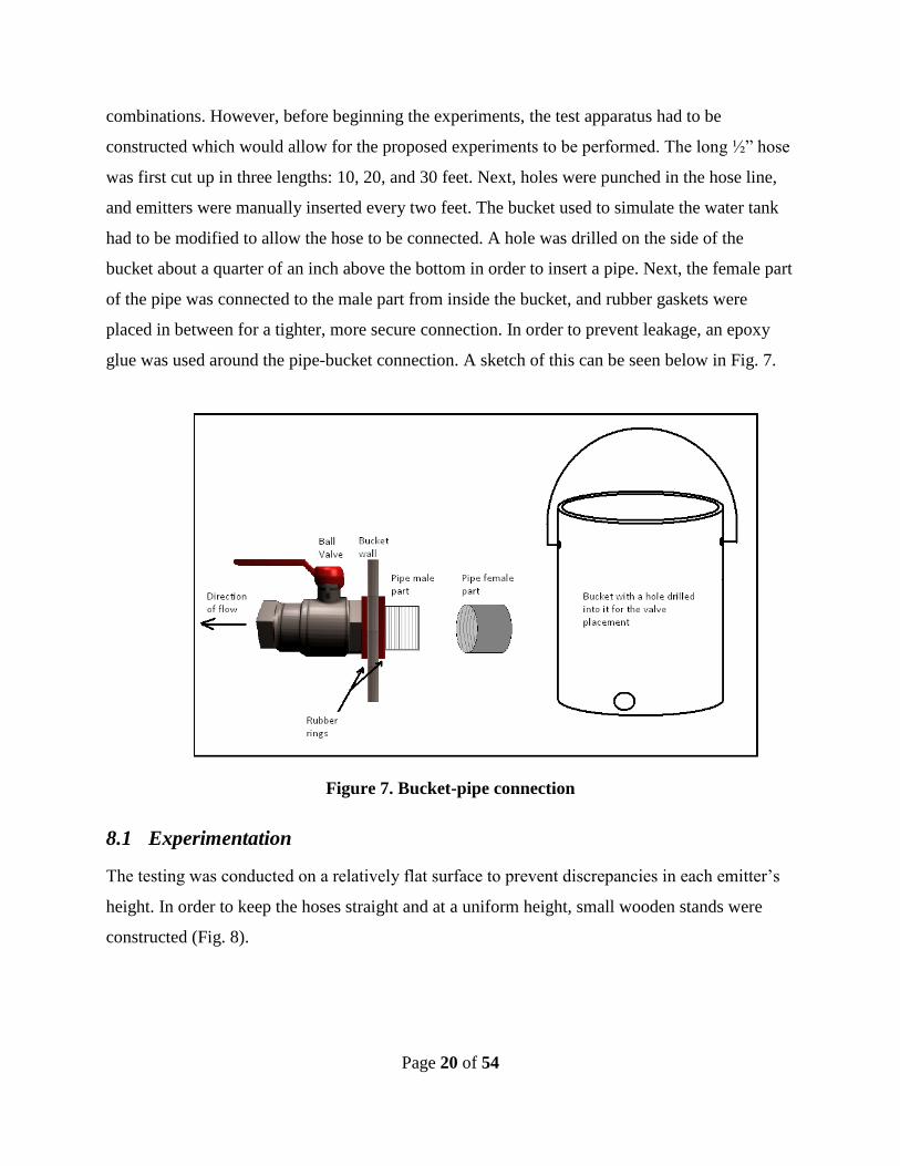
combinations. However, before beginning the experiments, the test apparatus had to be
constructed which would allow for the proposed experiments to be performed. The long ½” hose
was first cut up in three lengths: 10, 20, and 30 feet. Next, holes were punched in the hose line,
and emitters were manually inserted every two feet. The bucket used to simulate the water tank
had to be modified to allow the hose to be connected. A hole was drilled on the side of the
bucket about a quarter of an inch above the bottom in order to insert a pipe. Next, the female part
of the pipe was connected to the male part from inside the bucket, and rubber gaskets were
placed in between for a tighter, more secure connection. In order to prevent leakage, an epoxy
glue was used around the pipe-bucket connection. A sketch of this can be seen below in Fig. 7.
Figure 7. Bucket-pipe connection
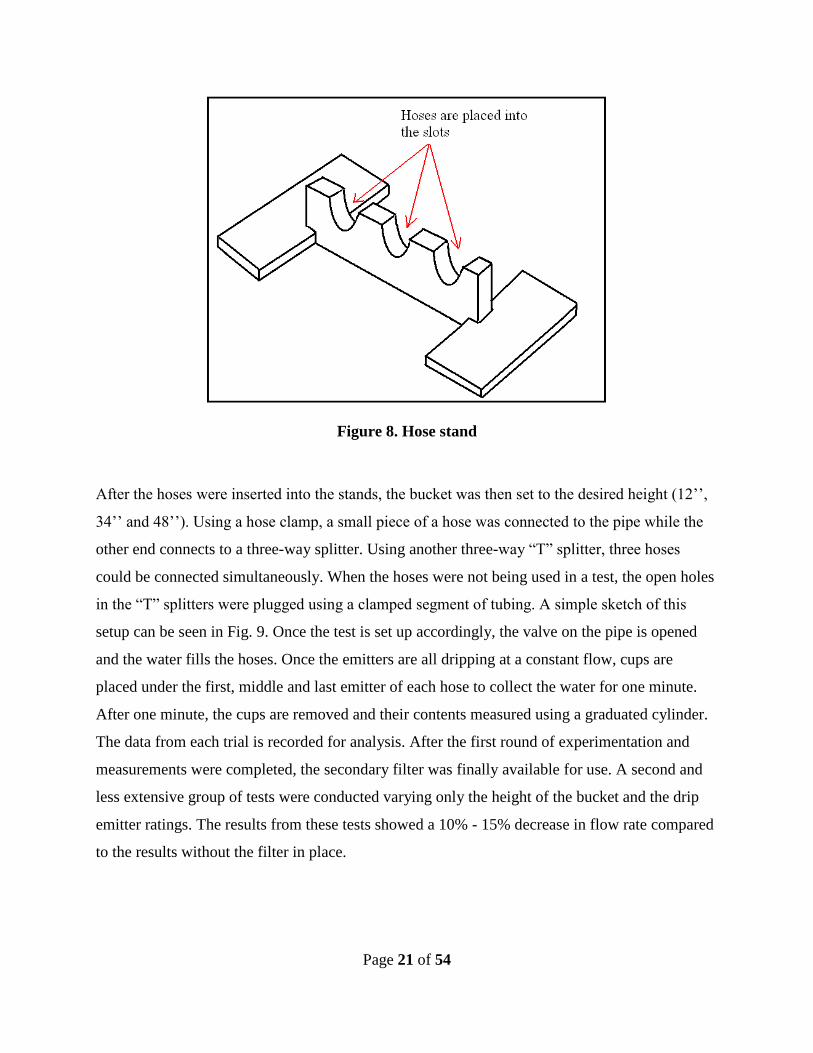
8.1 Experimentation
The testing was conducted on a relatively flat surface to prevent discrepancies in each emitter’s
height. In order to keep the hoses straight and at a uniform height, small wooden stands were
constructed (Fig. 8).
Page 21 of 54
Figure 8. Hose stand
After the hoses were inserted into the stands, the bucket was then set to the desired height (12’’,
34’’ and 48’’). Using a hose clamp, a small piece of a hose was connected to the pipe while the
other end connects to a three-way splitter. Using another three-way “T” splitter, three hoses
could be connected simultaneously. When the hoses were not being used in a test, the open holes
in the “T” splitters were plugged using a clamped segment of tubing. A simple sketch of this
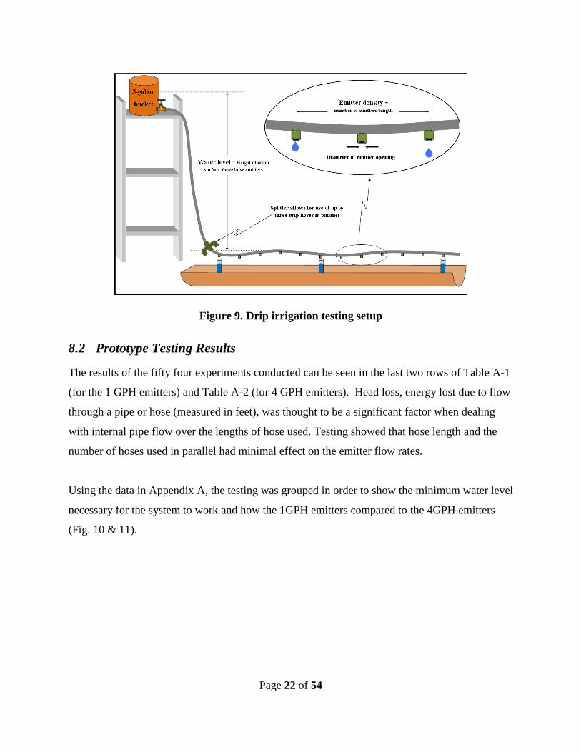
setup can be seen in Fig. 9. Once the test is set up accordingly, the valve on the pipe is opened
and the water fills the hoses. Once the emitters are all dripping at a constant flow, cups are
placed under the first, middle and last emitter of each hose to collect the water for one minute.
After one minute, the cups are removed and their contents measured using a graduated cylinder.
The data from each trial is recorded for analysis. After the first round of experimentation and
measurements were completed, the secondary filter was finally available for use. A second and
less extensive group of tests were conducted varying only the height of the bucket and the drip
emitter ratings. The results from these tests showed a 10% - 15% decrease in flow rate compared
to the results without the filter in place.
Page 22 of 54
Figure 9. Drip irrigation testing setup
8.2 Prototype Testing Results
The results of the fifty four experiments conducted can be seen in the last two rows of Table A-1
(for the 1 GPH emitters) and Table A-2 (for 4 GPH emitters). Head loss, energy lost due to flow
through a pipe or hose (measured in feet), was thought to be a significant factor when dealing
with internal pipe flow over the lengths of hose used. Testing showed that hose length and the
number of hoses used in parallel had minimal effect on the emitter flow rates.
Using the data in Appendix A, the testing was grouped in order to show the minimum water level
necessary for the system to work and how the 1GPH emitters compared to the 4GPH emitters
(Fig. 10 & 11).

Page 23 of 54
0.00
0.20
0.40
0.60
0.80
1.00
1.20
1.40
1.60
0 5 10 15 20 25 30
Test Number
Flo
w R
ate
(G
PH
per
foo
t)
Emitter Size = 1 GPH
Emitter Size = 4 GPH
12" water
level
34" water
level
48" water
level
Figure 10. Variance in flow rate by emitter size (water level grouping)
0.00
0.20
0.40
0.60
0.80
1.00
1.20
1.40
1.60
0 5 10 15 20
Test Number
Flo
w R
ate
(G
PH
per
foo
t)
Water Level = 12in
Water Level = 34in
Water Level = 48in1 GPH rated
emitters
4 GPH rated
emitters
Figure 11. Variance in flow rate by water level (emitter size grouping)

Page 24 of 54
The data make it clear that, by varying the water level and the emitter rating, it is possible to
achieve the necessary flow rate of 0.45GPH/ft (determined based upon a 2 hour watering time
for maximum infiltration, while considering time constraints of gardeners). While the effects of
hose length and number of hoses are of little consequence, scaling up the rest of the system for
watering at the Jardin de la Esparanza may induce some additional head loss due to friction
within the transport and drip hoses. A transport hose of sufficient diameter should help reduce
such losses. As the data show that flow rate varies greatly with water level, and since the tank to
be used in the final system is approximately 6’ in height, one can expect major changes in flow
rate as the tank either empties or fills over time. This must be accommodated for by either
adjusting the degree to which the watering valve will be opened. or by installing a pressure
reducing valve which will reduce the pressure to a constant value regardless of the height of the
water level within the tank. This pressure value will correspond to the determined water level
(1psi per 2.31ft of head), which will be selected after further analysis of the data.
9 Final System Design and Construction
The complete rainwater collection system was composed of four main assemblies: collection
system (gutters and PVC piping), filter system (primary and secondary filter), storage system
(tank and its foundation) and the distribution system (drip irrigation). All four components were
designed in accordance with the design criteria, as well as to have the most efficient and cost-
effective system as possible with the available financial resources.
9.1 Collection System
In order to catch as much rain as possible, an efficient collection system of gutters and PVC was
required to transport the water.
9.1.1 Materials and Design
The roof used as the collection surface did not have any guttering previously; this system
component was installed first. Much of the construction time was allocated for this step in order
to achieve the highest level of skill and precision possible. To minimize the weight of the
collection system, 3” and 4” foam-core PVC was implemented along with aluminum gutters.
Page 25 of 54
9.1.2 Methods and Construction
In order to put the gutters in place, it was easiest to install guttering one section at a time. Before
a section was installed, it was measured and scaled down to the length required for that particular
section of the building. Once the section was cut, it was simply placed onto metal “hangers” that
were screwed into the building wall. The gutter’s position was also outlined the with plumber’s
line before securing it with the hangers, as the optimal slope of the gutters to increase collection
capacity and prevent clogging is 1/8” over a 1’ length of gutter. Downspouts were placed at least
every 20’ along each run of gutter. To connect sections of the gutters to other sections,
downspouts, and elbows, gutter “joiners” were employed. They were secured with one-inch
rivets and gutter caulk.
The PVC piping was installed essentially the same as the gutters. Each of the segments was cut
to a length needed for that particular segment. Then they were placed at the same sloping angle
as the gutters so the water would flow in the desired direction. The PVC segments were
connected via PVC connectors and, depending on the expected water flow on a particular side of
the building, the group used either a 3” or a 4” diameter PVC pipe. The pipes were secured next
to the building wall using copper strapping. The strapping was cut down to a needed size
(depending on the PVC diameter), wrapped around the pipe and screwed into the building wall.
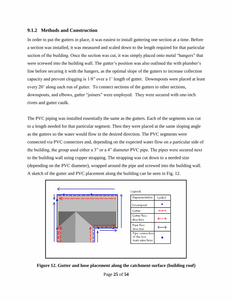
A sketch of the gutter and PVC placement along the building can be seen in Fig. 12.
Figure 12. Gutter and hose placement along the catchment surface (building roof)
Page 26 of 54
The water flow between the gutters and the PVC piping was secured via downspouts and various
PVC connectors, which were used depending on the downspout position with respect to the
piping. All of the piping was directed to the location of the installed tank, making for an easy
transition from transport to storage.
9.1.3 Results
After some rain had fallen, it was apparent that the gutters and PVC were working properly.
They directed the rainwater into the storage tank successfully. Additionally, the construction of
the design to support the gutters and PVC had lasted a significant amount of time to show that
they were sturdy and stable.
The leak testing, conducted by examining the collection and transportation components of the
system while water is running across/through them, was slightly less successful. It is apparent
that there is a small amount of leakage at the collection system and transportation system
interface. Two guttering elbows were used to bridge the gap between the roof’s fascia and the
underlying outer wall of the building. They connected the collection (guttering) downspouts to
the PVC transportation. These fittings were not precise (not the intended 90 degree angle)
because the fascia of the house, instead of being vertical, is angled perpendicular to the slope of
the roof. Thus all the leaking in the collection and transportation system occurred at this
interface, but can easily be fixed by using caulking in the gaps.
9.2 Filtration System
The filtration system was one of the most essential parts of the system in order to make it low
maintenance and employ a drip irrigation distribution method. The primary filter was placed
before the tank’s inlet to remove large particulates, such as leaves, twigs, pollen and bugs. The
secondary filter was placed after the tank’s outlet valve to remove small dirt particles that could
clog a drip emitter.
Page 27 of 54
9.2.1 Materials and Design
The primary filter was manually constructed, while the secondary filter was purchased from a
store. In order for the primary filter to operate successfully, several details such as the angle of
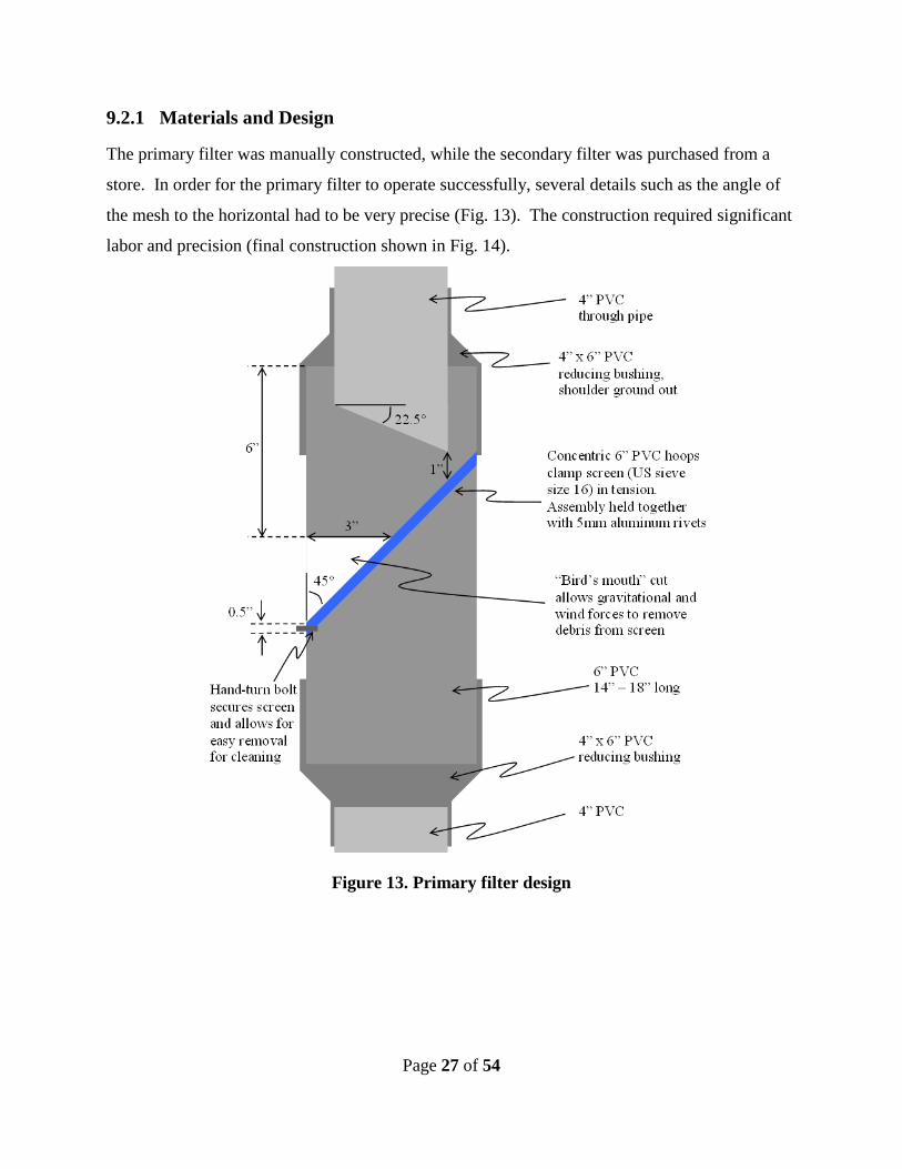
the mesh to the horizontal had to be very precise (Fig. 13). The construction required significant
labor and precision (final construction shown in Fig. 14).
Figure 13. Primary filter design
Page 28 of 54
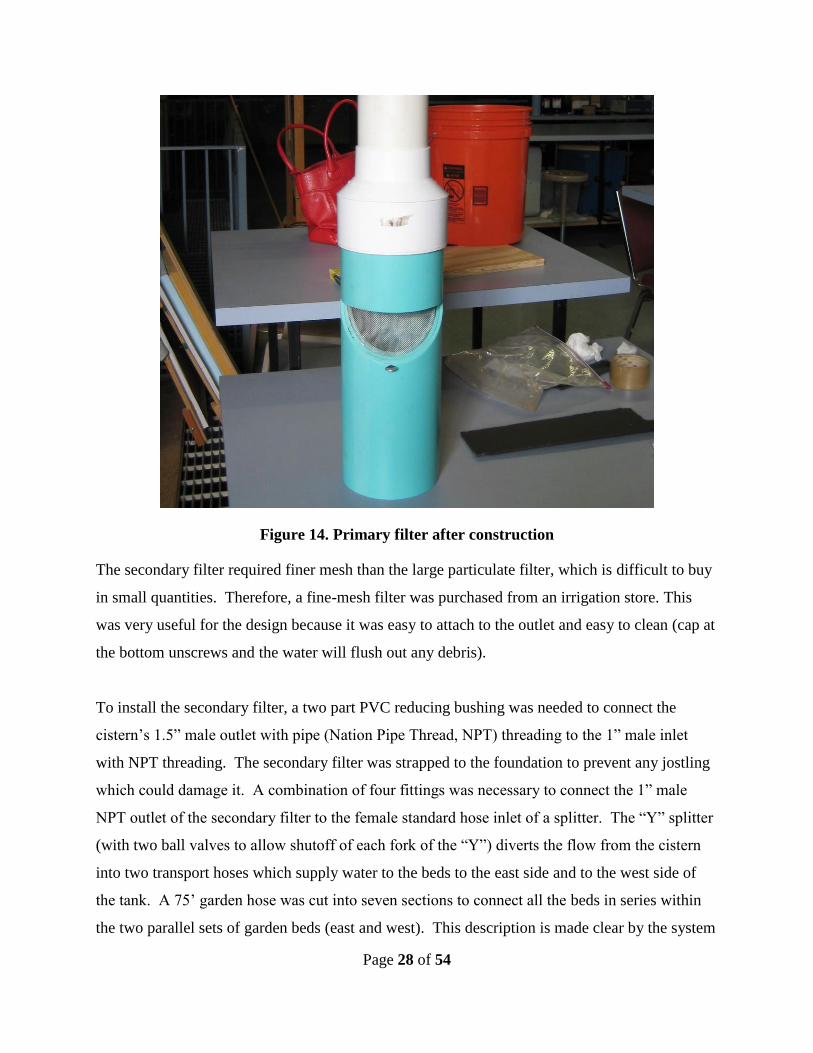
Figure 14. Primary filter after construction
The secondary filter required finer mesh than the large particulate filter, which is difficult to buy
in small quantities. Therefore, a fine-mesh filter was purchased from an irrigation store. This
was very useful for the design because it was easy to attach to the outlet and easy to clean (cap at
the bottom unscrews and the water will flush out any debris).
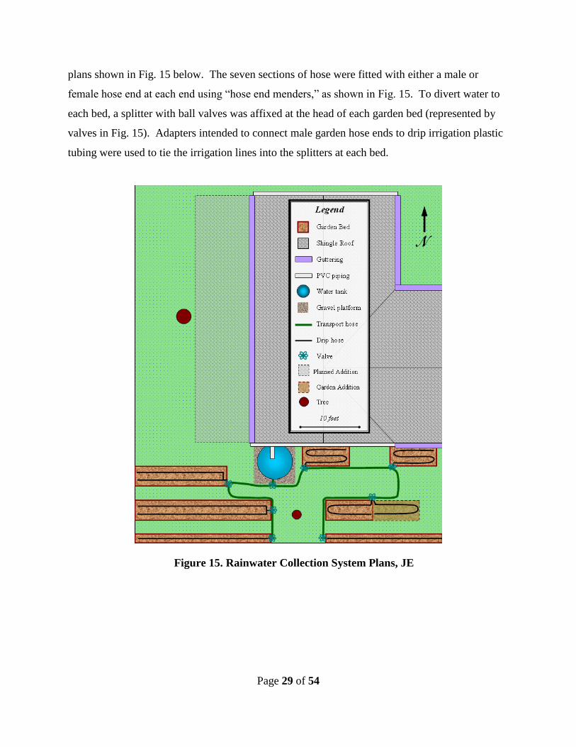
To install the secondary filter, a two part PVC reducing bushing was needed to connect the
cistern’s 1.5” male outlet with pipe (Nation Pipe Thread, NPT) threading to the 1” male inlet
with NPT threading. The secondary filter was strapped to the foundation to prevent any jostling
which could damage it. A combination of four fittings was necessary to connect the 1” male
NPT outlet of the secondary filter to the female standard hose inlet of a splitter. The “Y” splitter
(with two ball valves to allow shutoff of each fork of the “Y”) diverts the flow from the cistern
into two transport hoses which supply water to the beds to the east side and to the west side of
the tank. A 75’ garden hose was cut into seven sections to connect all the beds in series within
the two parallel sets of garden beds (east and west). This description is made clear by the system
Page 29 of 54
plans shown in Fig. 15 below. The seven sections of hose were fitted with either a male or
female hose end at each end using “hose end menders,” as shown in Fig. 15. To divert water to
each bed, a splitter with ball valves was affixed at the head of each garden bed (represented by
valves in Fig. 15). Adapters intended to connect male garden hose ends to drip irrigation plastic
tubing were used to tie the irrigation lines into the splitters at each bed.
Figure 15. Rainwater Collection System Plans, JE
Page 1
9.2.2 Methods and Construction
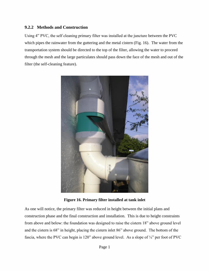
Using 4” PVC, the self cleaning primary filter was installed at the juncture between the PVC
which pipes the rainwater from the guttering and the metal cistern (Fig. 16). The water from the
transportation system should be directed to the top of the filter, allowing the water to proceed
through the mesh and the large particulates should pass down the face of the mesh and out of the
filter (the self-cleaning feature).
Figure 16. Primary filter installed at tank inlet
As one will notice, the primary filter was reduced in height between the initial plans and
construction phase and the final construction and installation. This is due to height constraints
from above and below: the foundation was designed to raise the cistern 18” above ground level
and the cistern is 68” in height, placing the cistern inlet 86” above ground. The bottom of the
fascia, where the PVC can begin is 120” above ground level. As a slope of ¼” per foot of PVC
Page 2
was desired (to expedite water transport to the cistern and clean out any built up debris in the
piping), and the longest PVC run is 84’, the PVC dropped below the fascia 21” to 99” above
ground level. Thus, the large particulate filter, its connecting tee and its 90° elbow which
attaches it to the cistern had to all fit into the 13” between the PVC and the cistern inlet.
9.2.3 Results
It was very difficult to simulate the final operation of the filter during prototype testing because
the angle of the water hitting the screen was the most essential variable to determine if the design
was successful. However, once it was installed into the system at JE, it was no longer possible to
isolate the filter as an individual system and test its efficiency. Therefore, the filter was only
tested visually.
While the filter effectively removes all large debris, a significant amount of water runs down the
angled screen and off the filter instead of through the mesh and down into the tank. Adjustments
will have to be made to rectify this problem; otherwise the system may fall below the projected
85% collection efficiency and fail to meet the water demand at peak months on a typical year.
Also, the filter is not entirely “self-cleaning” and requires some manual cleaning to remove
buildup which adheres to the mesh.
9.3 Tank and Foundation Installation
The size and efficiency of the tank was very important because the tank is the entire storage
capacity for the system. Many of the calculations done in this report are made assuming a full
tank at the start of the year, 1200 gallons. In order to successfully harness the energy available
from gravity, the tank had to be raised 12”. Research was done to formulate the best possible
design for the platform.
To install the tank, it was hoisted onto the foundation, centered, and aligned such that the outlet
was most accessible and the inlet would meet up with the PVC piping.
Page 3
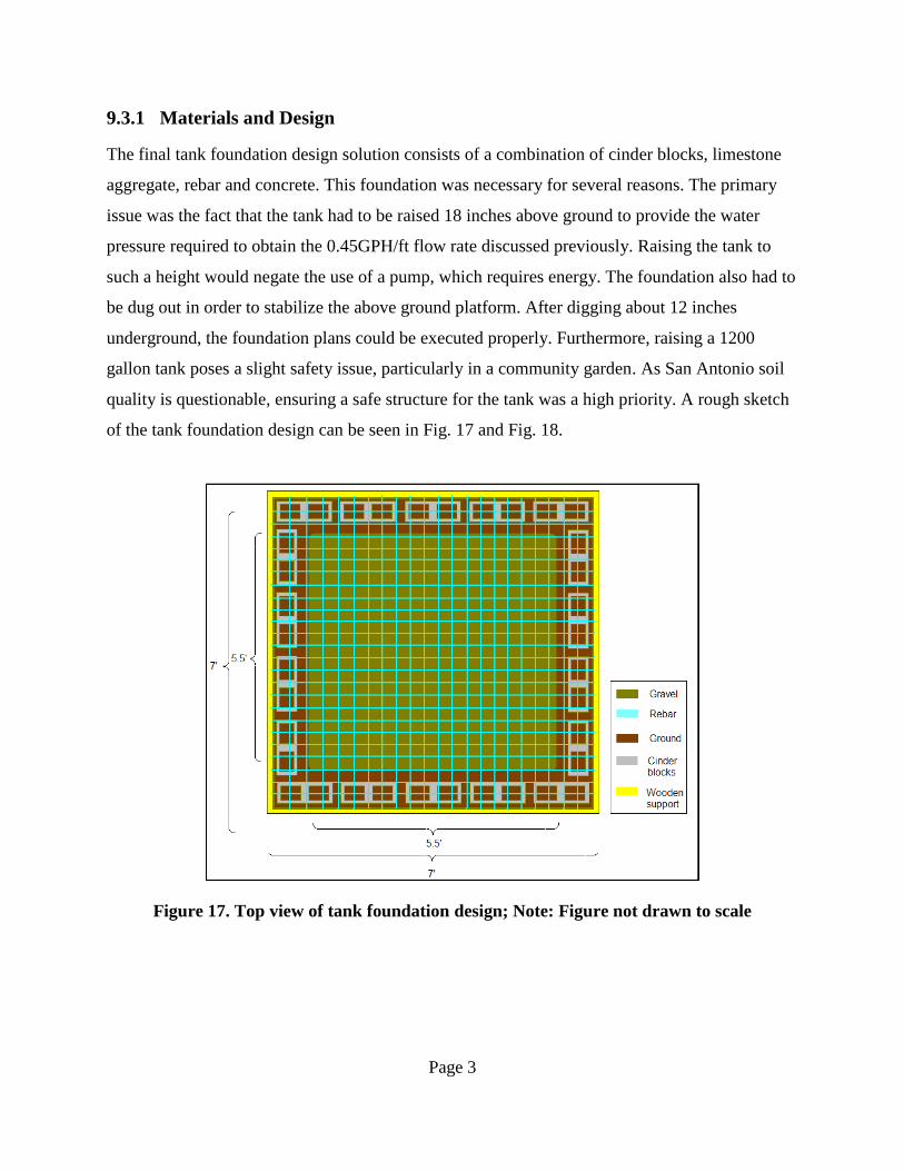
9.3.1 Materials and Design
The final tank foundation design solution consists of a combination of cinder blocks, limestone
aggregate, rebar and concrete. This foundation was necessary for several reasons. The primary
issue was the fact that the tank had to be raised 18 inches above ground to provide the water
pressure required to obtain the 0.45GPH/ft flow rate discussed previously. Raising the tank to
such a height would negate the use of a pump, which requires energy. The foundation also had to
be dug out in order to stabilize the above ground platform. After digging about 12 inches
underground, the foundation plans could be executed properly. Furthermore, raising a 1200
gallon tank poses a slight safety issue, particularly in a community garden. As San Antonio soil
quality is questionable, ensuring a safe structure for the tank was a high priority. A rough sketch
of the tank foundation design can be seen in Fig. 17 and Fig. 18.
Figure 17. Top view of tank foundation design; Note: Figure not drawn to scale
Page 4
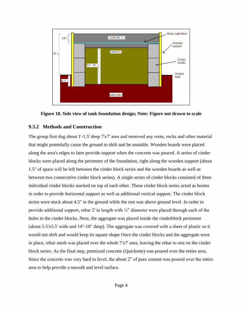
Figure 18. Side view of tank foundation design; Note: Figure not drawn to scale
9.3.2 Methods and Construction
The group first dug about 1'-1.5' deep 7'x7' area and removed any roots, rocks and other material
that might potentially cause the ground to shift and be unstable. Wooden boards were placed
along the area's edges to later provide support when the concrete was poured. A series of cinder
blocks were placed along the perimeter of the foundation, right along the wooden support (about
1.5" of space will be left between the cinder block series and the wooden boards as well as
between two consecutive cinder block series). A single series of cinder blocks consisted of three
individual cinder blocks stacked on top of each other. These cinder block series acted as beams
in order to provide horizontal support as well as additional vertical support. The cinder block
series were stuck about 4.5" in the ground while the rest was above ground level. In order to
provide additional support, rebar 2' in length with ¼” diameter were placed through each of the
holes in the cinder blocks. Next, the aggregate was placed inside the cinderblock perimeter
(about 5.5'x5.5' wide and 14"-18" deep). The aggregate was covered with a sheet of plastic so it
would not shift and would keep its square shape Once the cinder blocks and the aggregate were
in place, rebar mesh was placed over the whole 7'x7' area, leaving the rebar to rest on the cinder
block series. As the final step, premixed concrete (Quickrete) was poured over the entire area.
Since the concrete was very hard to level, the about 2” of pure cement was poured over the entire
area to help provide a smooth and level surface.
Page 5
The final foundation was 18" high and square shaped (7’x7’). The pressure that the tank will
exert on the foundation when completely full will be about 2.5 psi, which is less than an average
person exerts on the ground when standing on two feet. Therefore the group is confident that this
design will provide more than enough support for the tank and the cinder block beams will
provide horizontal support so the foundation, and thus the tank, do not shift.
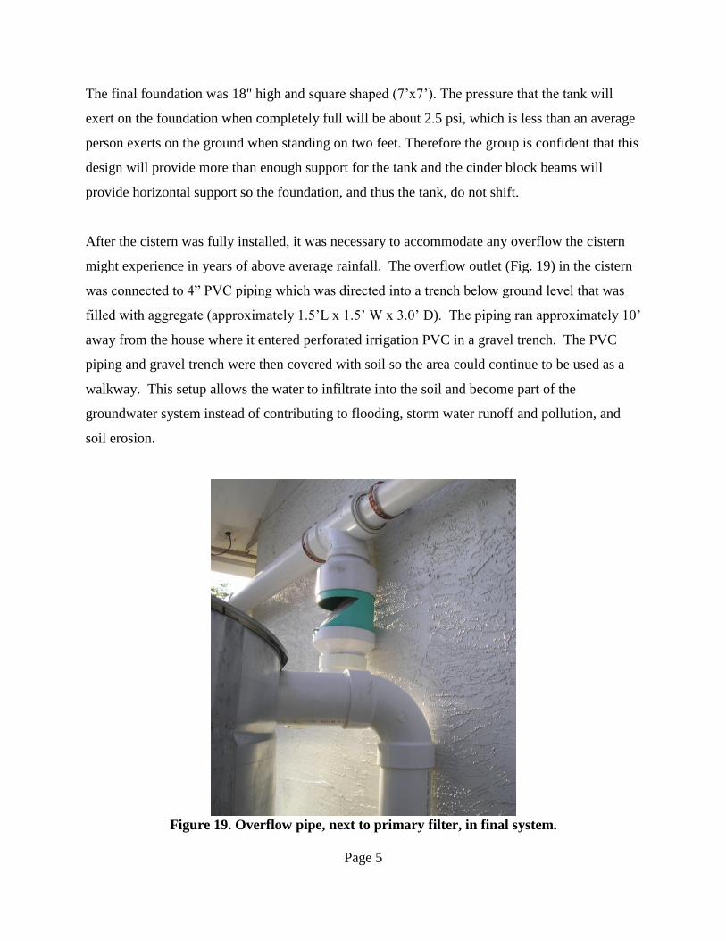
After the cistern was fully installed, it was necessary to accommodate any overflow the cistern
might experience in years of above average rainfall. The overflow outlet (Fig. 19) in the cistern
was connected to 4” PVC piping which was directed into a trench below ground level that was
filled with aggregate (approximately 1.5’L x 1.5’ W x 3.0’ D). The piping ran approximately 10’
away from the house where it entered perforated irrigation PVC in a gravel trench. The PVC
piping and gravel trench were then covered with soil so the area could continue to be used as a
walkway. This setup allows the water to infiltrate into the soil and become part of the
groundwater system instead of contributing to flooding, storm water runoff and pollution, and
soil erosion.
Figure 19. Overflow pipe, next to primary filter, in final system.
Page 6
9.3.3 Results
The tank has performed as expected. There are no leaks in the design from Texas Metal
Cisterns. The inlet and outlet of the tank were cohesive with the inlet, overflow and outlet valve.
Presently, positive results have been achieved with the foundation design and construction.
There is some minor cracking in the cement on the surface of the platform. The cracks are only
about a millimeter wide and seem to be only surface-oriented which signifies that the most
important part, the core, has dried well and thus strengthened properly.
9.4 Distribution System
To satisfy one of the main design goals of the project, a successful distribution system is
essential. It consists of two main transport hoses, which each feed water to half of the garden.
These hoses run along their respective halves of the garden, sending water down the drip hoses
in each bed. At each bed, there is a valve which controls if that bed receives water.
9.4.1 Materials and Design
The layout of the irrigation system was designed following recommendations of the Texas A&M
University System Agriculture Program (2). Closely spaced vegetables (less than two feet
between plants), like those at JE, in medium coarseness soil, like that of its garden beds, will
thrive with a watering system that allows for one drip hose per row of vegetables, with one
emitter placed every 24” along the hose. Based upon prototype testing, the team determined that
4GPH emitters with at least 12” of head of water would provide the necessary flow rate of
0.45GPH per foot of hose.
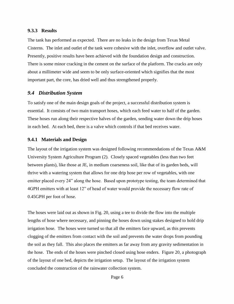
The hoses were laid out as shown in Fig. 20, using a tee to divide the flow into the multiple
lengths of hose where necessary, and pinning the hoses down using stakes designed to hold drip
irrigation hose. The hoses were turned so that all the emitters face upward, as this prevents
clogging of the emitters from contact with the soil and prevents the water drops from pounding
the soil as they fall. This also places the emitters as far away from any gravity sedimentation in
the hose. The ends of the hoses were pinched closed using hose enders. Figure 20, a photograph
of the layout of one bed, depicts the irrigation setup. The layout of the irrigation system
concluded the construction of the rainwater collection system.
Page 7
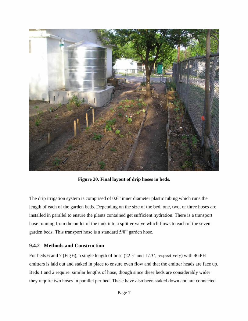
Figure 20. Final layout of drip hoses in beds.
The drip irrigation system is comprised of 0.6” inner diameter plastic tubing which runs the
length of each of the garden beds. Depending on the size of the bed, one, two, or three hoses are
installed in parallel to ensure the plants contained get sufficient hydration. There is a transport
hose running from the outlet of the tank into a splitter valve which flows to each of the seven
garden beds. This transport hose is a standard 5/8” garden hose.
9.4.2 Methods and Construction
For beds 6 and 7 (Fig 6), a single length of hose (22.3’ and 17.3’, respectively) with 4GPH
emitters is laid out and staked in place to ensure even flow and that the emitter heads are face up.
Beds 1 and 2 require similar lengths of hose, though since these beds are considerably wider
they require two hoses in parallel per bed. These have also been staked down and are connected
Page 8
to the tank. Beds 3, 4, and 5 are about 8’ in length and roughly 4’ wide. These beds have three
hoses in parallel per bed and are staked down like the rest of the garden. The hoses are attached
to the tank via a standard size garden hose. The beds containing 2 or three hoses are connected
together using splitters, and then connected to the garden hose. Each garden bed has its own ball
valve to allow for watering directly at bed site.
9.4.3 Results
When the distribution system was tested, all of the emitters were dripping, which showed that
none of them had gotten clogged since installation. They were all functioning properly, which
suggests that the particulates capable of clogging the system are being removed effectively by
the combination of the primary and secondary filters.
The flow rate testing on site at JE is essential to determine if the system is able to produce the
flow rates needed (0.45GPH/ft) to infiltrate the soil to the root systems within the timeframe of
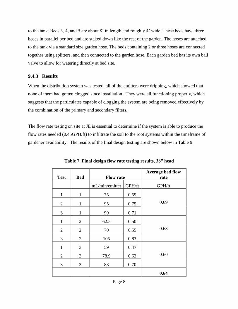
gardener availability. The results of the final design testing are shown below in Table 9.
Table 7. Final design flow rate testing results, 36” head
Test Bed Flow rate
Average bed flow
rate
mL/min/emitter GPH/ft GPH/ft
1 1 75 0.59
0.69 2 1 95 0.75
3 1 90 0.71
1 2 62.5 0.50
0.63 2 2 70 0.55
3 2 105 0.83
1 3 59 0.47
0.60 2 3 78.9 0.63
3 3 88 0.70
0.64

Page 9
The results show that, as expected, flow rates decrease as distance of garden bed from tank
increases. While the losses in flow rate are significant (13.0%), it is not clear that the lower flow
rate will have significant negative effects upon the health of the plants in the beds furthest away
from the tank. Also, the system includes valves at each bed, and such versatility allows for
watering selected beds to accommodate any differences in flow rates.
Testing the final design of the irrigation system in place at el Jardin de la Esperanza using the
same methodology as the tests conducted in the lab setting allows for data comparison.
Averaging the flow rates for the three beds yields an overall flow rate of 0.64 GPH/ft. While this
is above the necessary optimal flow rate of 0.45 GPH/ft (and could be reduced to this value by
partially closing the valve at the outlet of the tank) it is not necessarily true that the optimal flow
rate can be attained at every water level. Plotting the flow rate against water level in the same
plot as the laboratory testing shows that the flow rate is lower than expected (see Fig. 21 below).
Figure 21. Comparison of final design testing with laboratory testing
Page 10
To generate the expected flow rate at every water level, the slopes of the laboratory testing with a
clean filter and with a partially blocked filter were averaged (this relation is substantiated by a
qualitative analysis of the filter status which showed partial sedimentation, but less than
experienced in laboratory testing). Then the final design data describing a flow rate of 0.64
GPH/ft was extrapolated to the entire water level range using the average slope. Such an
extrapolation shows that the system will drop below the optimal flow rate for water levels less
than 22”. As the tank is elevated 12” above the raised beds, this means that the flow rate will be
less than optimal when there is less than 10” of water in the tank. When the tank is approaching
empty (water level is 12” above garden beds), the flow rate will only be 0.31 GPH/ft, or 69% of
the desired flow rate.
10 Analyzing the Design
After construction was completed at JE, the next step was to analyze the design to determine
how well it satisfied the original criteria and determine how successful the system operation was.
10.1 Satisfaction of Criterion
In the early stages of the design project, initial design criteria were put together. Since that time,
new criteria have been added to the project, based on the specifications of the client and
additional constraints encountered.
10.1.1 Budget and Location
The most obvious criteria to adhere to was the budget – beginning with $1000 from the
department. Once it had been decided to undergo a construction process to build the design at
full-scale, it was immediately apparent that the tank alone would consume nearly the entire
budget. Fortunately, the client, Bexar Land Trust (associated with JE), offered to contribute the
$800 budget they had set aside to build a system similar to the one proposed. Unfortunately, the
budget was still exceeded by $29.60.
Page 11
The proposed system is ideal for a small garden or greenhouse, much like the one at JE. While it
took considerable time to find a location, it functioned as a perfect location to implement the
system. A similar system could also easily be implemented in the home.
10.1.2 Maintenance
When selecting the tank, careful considerations were made of initial criterion such as cheap but
weather-resistant tank material (including the discouragement of algae growth) and the presence
of an inlet, outlet and overflow valve. To get a custom tank, Texas Metal Cisterns in San
Marcos, Texas was contracted for construction. There was originally a desire to have a gauge on
the tank that would show the level of the water. Presently, this feature has not been incorporated,
but a compromise could be made later.
Another goal was to build or use filters with long life spans. The primary filter was constructed
according to a model seen at the Montgomery County Extension Office in Conroe, Texas. In
addition to the initial observations of the filter, members of the team spoke with the designer of
the self-cleaning filter, Jim Bundscho. He explained the specifications necessary to make the
filter work. The secondary filter was purchased to simplify construction for the team; it was also
extremely difficult to find small quantities of the mesh required (US sieve size 100).
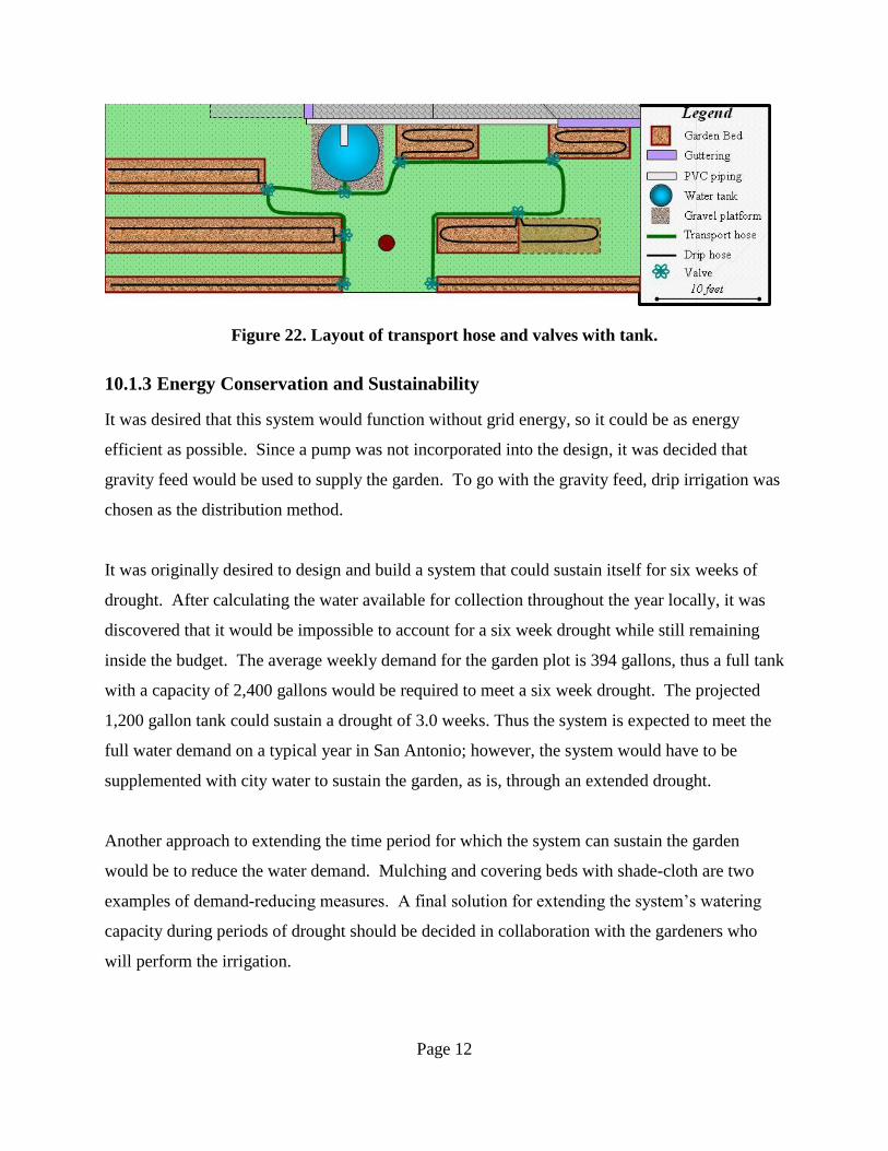
The plan was to design the system so that the gardener would only have roughly 15 minutes of
maintenance per week. Once the contract with JE had been signed, it was discovered that they
wanted the system to leave room for some “hands-on” maintenance from the gardeners. They
preferred that the system was not self-sufficient because they had people who wanted to put time
into the garden. It was decided to minimize most of the labor that would be required to set up
watering at each plot (shown in Fig. 22 below). There is a main transport hose running from the
tank in both directions (east and west). This hose runs underground to reduce the potential of
people tripping over it. With this design for the system, the gardener can turn on the main valve
at the tank, and then open or close the valves at each bed at his/her leisure.
Page 12
Figure 22. Layout of transport hose and valves with tank.
10.1.3 Energy Conservation and Sustainability
It was desired that this system would function without grid energy, so it could be as energy
efficient as possible. Since a pump was not incorporated into the design, it was decided that
gravity feed would be used to supply the garden. To go with the gravity feed, drip irrigation was
chosen as the distribution method.
It was originally desired to design and build a system that could sustain itself for six weeks of
drought. After calculating the water available for collection throughout the year locally, it was
discovered that it would be impossible to account for a six week drought while still remaining
inside the budget. The average weekly demand for the garden plot is 394 gallons, thus a full tank
with a capacity of 2,400 gallons would be required to meet a six week drought. The projected
1,200 gallon tank could sustain a drought of 3.0 weeks. Thus the system is expected to meet the
full water demand on a typical year in San Antonio; however, the system would have to be
supplemented with city water to sustain the garden, as is, through an extended drought.
Another approach to extending the time period for which the system can sustain the garden
would be to reduce the water demand. Mulching and covering beds with shade-cloth are two
examples of demand-reducing measures. A final solution for extending the system’s watering
capacity during periods of drought should be decided in collaboration with the gardeners who
will perform the irrigation.
Page 13
10.2 Effectiveness of the System
After the project’s completion, it was noticed during testing that there are some leaks in the
transport system as mentioned previously. Again, this minor inconvenience can be fixed by
simply using a waterproof sealant or caulk.
One concern is the efficiency of the primary filter, as it did not test well in the lab. A significant
amount of water was running directly down the surface of the mesh, and not going through. Part
of the problem during testing was that the water was poured straight down the tube onto the
filter. While it was assumed the filter would perform as desired once installed in the system, it
unfortunately did not. Again, some water was lost through this system and will need to be
corrected in order to provide the necessary effectiveness.
Another area tested was the effectiveness of the drip irrigation system. The hoses and emitters
performed very well during the prototype testing. Fortunately, they behaved in a similar fashion
upon testing on location at JE. Assuming there is more than 10” of water height in the tank, the
drip irrigation system will perform at a higher rate than needed. When it drops below 10”
however, the emitters will not meet the minimum required flow rate of 0.45GPH/ft.
The actual collection percentage is currently a topic of discussion. For calculations, 85%
efficiency was assumed to account for evaporation and the general climate of central Texas. It is
highly desired that the actual number is not less than the estimated value. There is no precise
way to test for this.
10.3 Problems Encountered
As stated above, few problems have been encountered during the project. There was slight
concern that a permit would need to be obtained for the foundation. After doing some research
on permits according to the International Building Code, it was discovered that the tank was
exempt from its stipulations because the tank capacity does not exceed 5,000 gallons and the
height to diameter ratio does not exceed 2:1.
Page 14
The main problem encountered was with the budget. Attempting to produce a full scale
construction project on a budget of $1800 proved to be very challenging, even with donations
received. Also, two receipts were misplaced and group members ended up absorbing those
costs instead of coming out of the budget.
Time was another concern, as this project was implemented in a garden for daily use by a client.
To date, the project is complete with a few minor adjustments that should be made; the
construction process began March 1.
10.4 Maintenance and Upkeep
In order for the people at JE to maintain and keep the system within their garden, a maintenance
manual will be provided should any questions or problems arise. This manual will be short, and
geared towards users with non technical backgrounds. This can be found in Appendix B.
11 Conclusions and Recommendations
Although the overall project is complete, there were still problems encountered along the way
that required extra time and attention. Upon testing of the final product, a few unanticipated
problems surfaced as well. When testing the system as described above, some leaks were
observed; first in the gutter assembly and more in the primary filter. The “S” curves connecting
the gutter to the PVC transport pipe were leaking at the connection of the two bends; this was
most likely due to bending of the components themselves either during transport or construction.
The primary filter, which was the designated self cleaning filter, was installed with the intent of
reducing maintenance. However, there was also some obvious water loss at this point in the
system as well. The overall system, however, did collect the water that entered the system via the
roof and transport pipes, as well as deliver water from the storage tank to the garden beds
through the system of drip hoses. While the system ultimately met the goals outlined by the
team earlier in the year, these minor problems obviously still have an effect.
In order for the system to operate more effectively, it is suggested that the design of the primary
filter be reworked, as it appears to be faulty. This problem could have been sidestepped by more
thorough testing in earlier stages of the design. While the idea of a self cleaning filter is a good
Page 15
one, the design specifications received were inadequate for this project. Another option is to
leave the primary filter out altogether. Going back to the alternatives section, perhaps the
GutterFilter option that was examined earlier would have been a better fit for this system. It
would have continued to keep the system low maintenance while filtering out the larger particles
that were undesirable in the storage tank. Lastly, a simple screen filter, again of U.S sieve size
16, could have been placed in the gutter at the downspouts to prevent particulate matter from
entering the stored water. However, this would require a manual sweep of the gutter after each
rain event, which significantly increases the maintenance of the system.
For the “S” curves in the transport system, more care could have been used when joining pieces
together as to not bend the metal. Another option would have been to use a higher quality gutter
product made of a heavier weight metal, though this would add to the cost of the system. In order
to remedy the system in place at JE, a clear waterproof sealant will be used to fill in the gaps
created by the bent guttering.
While this project was ultimately successful, there were two other factors that proved difficult:
time and money. Initially given a budget of $1000, an additional $800 was donated from JE from
funds that were allocated for a similar project. By combining these resources, the budget nearly
doubled. However, when implementing a full scale construction project, the initial budget
proposal and final budget summary are usually not the same. Furthermore, the initial budget
estimate did not account for the foundation that was later added. The group was fortunate to
receive material donations from local businesses to help remedy such unexpected costs. Vulcan
Materials graciously donated six tons of aggregate which was used for the foundation, and
Ferguson Enterprises donated 140’ of PVC and fittings for the transport system. Without these
two donations the project would have suffered greatly. For future student groups considering a
full scale construction project, it is highly recommended that they seek out donations as well, and
leave room in their budget for unexpected costs.
Additionally, it was difficult to keep the construction process on schedule. Each segment of
construction took longer than anticipated to complete and there were problems encountered
along the way which took additional time to address. There were also times when more materials
were needed to complete a phase; this slowed progress considerably as construction bottlenecked

Page 16
while the team waited on one member to attain the additional materials. Again, for future groups
who are on a schedule, not only is it wise to keep all necessary tools in the same place at the job
site, it is imperative that all necessary materials are readily available to keep the project moving
at a smooth pace.
Ultimately, the rainwater catchment system implemented at JE was a successful design. After
testing of the system was complete, the observations made allowed for the above
recommendations to be made. These solutions can be corrected for future work. However, the
system caught water, transported it to an onsite storage facility, filtered out particulate matter,
and delivered the water to a garden plot as outlined in the preliminary problem statement.

Page 17
12 References
1. The Texas Manual on Rainwater Harvesting, 3rd
Edition. Texas Water Development Board.
http://www.twdb.state.tx.us/publications/reports/RainwaterHarvestingManual_3rdedition.
pdf.
2. The Agriculture Program of the Texas A&M University System.
http://aggie-horticulture.tamu.edu/extension/homelandscape/water/water.html
3. Weather Underground. 2008. http://www.wunderground.com
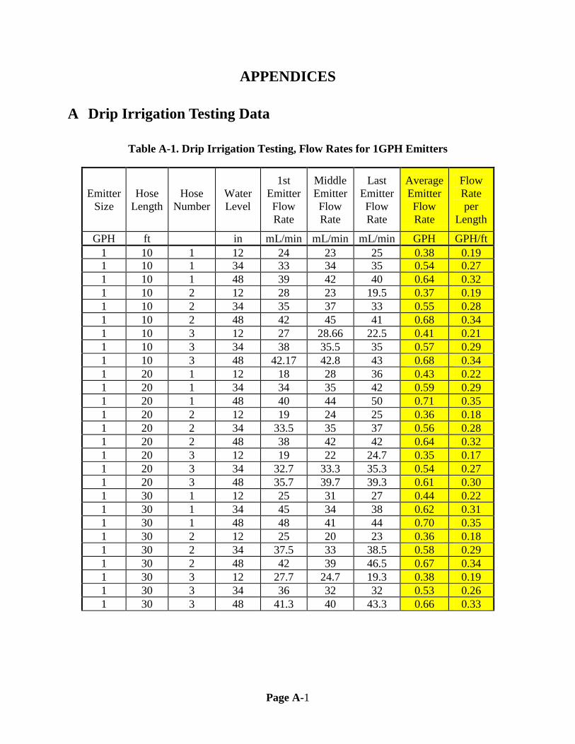
Page A-1
APPENDICES
A Drip Irrigation Testing Data
Table A-1. Drip Irrigation Testing, Flow Rates for 1GPH Emitters
Emitter
Size
Hose
Length
Hose
Number
Water
Level
1st
Emitter
Flow
Rate
Middle
Emitter
Flow
Rate
Last
Emitter
Flow
Rate
Average
Emitter
Flow
Rate
Flow
Rate
per
Length
GPH ft in mL/min mL/min mL/min GPH GPH/ft
1 10 1 12 24 23 25 0.38 0.19
1 10 1 34 33 34 35 0.54 0.27
1 10 1 48 39 42 40 0.64 0.32
1 10 2 12 28 23 19.5 0.37 0.19
1 10 2 34 35 37 33 0.55 0.28
1 10 2 48 42 45 41 0.68 0.34
1 10 3 12 27 28.66 22.5 0.41 0.21
1 10 3 34 38 35.5 35 0.57 0.29
1 10 3 48 42.17 42.8 43 0.68 0.34
1 20 1 12 18 28 36 0.43 0.22
1 20 1 34 34 35 42 0.59 0.29
1 20 1 48 40 44 50 0.71 0.35
1 20 2 12 19 24 25 0.36 0.18
1 20 2 34 33.5 35 37 0.56 0.28
1 20 2 48 38 42 42 0.64 0.32
1 20 3 12 19 22 24.7 0.35 0.17
1 20 3 34 32.7 33.3 35.3 0.54 0.27
1 20 3 48 35.7 39.7 39.3 0.61 0.30
1 30 1 12 25 31 27 0.44 0.22
1 30 1 34 45 34 38 0.62 0.31
1 30 1 48 48 41 44 0.70 0.35
1 30 2 12 25 20 23 0.36 0.18
1 30 2 34 37.5 33 38.5 0.58 0.29
1 30 2 48 42 39 46.5 0.67 0.34
1 30 3 12 27.7 24.7 19.3 0.38 0.19
1 30 3 34 36 32 32 0.53 0.26
1 30 3 48 41.3 40 43.3 0.66 0.33

Page A-2
Table A-2. Drip Irrigation Testing, Flow Rates for 4GPH Emitters
Emitter
Size
Hose
Length
Hose
Number
Water
Level
1st
Emitter
Flow
rate
Middle
Emitter
Flow
rate
Last
Emitter
Flow
rate
Avg
Emitter
flow
rate
Flow
rate per
Length
GPH ft in mL/min mL/min mL/min GPH GPH/ft
4 10 1 12 74 84 88 1.30 0.65
4 10 1 34 129 148 149 2.25 1.13
4 10 1 48 159 186 185 2.80 1.40
4 10 2 12 71 80.5 85 1.25 0.62
4 10 2 34 114 145 143 2.12 1.06
4 10 2 48 163.5 177 171 2.70 1.35
4 10 3 12 65.7 73.3 67.3 1.09 0.55
4 10 3 34 113.5 122.2 120 1.88 0.94
4 10 3 48 171.3 176.5 174.7 2.76 1.38
4 20 1 12 76 74 62 1.12 0.56
4 20 1 34 137 146 134 2.20 1.10
4 20 1 48 166 154 170 2.59 1.29
4 20 2 12 53 59 55 0.88 0.44
4 20 2 34 122 140 123 2.03 1.02
4 20 2 48 148 163 154 2.46 1.23
4 20 3 12 55.3 61.3 58.7 0.93 0.46
4 20 3 34 84 93.3 85 1.39 0.69
4 20 3 48 142 148 160 2.38 1.19
4 30 1 12 67 67 65 1.05 0.53
4 30 1 34 92 96 82 1.43 0.71
4 30 1 48 101 105 100 1.62 0.81
4 30 2 12 67 63 53 0.97 0.48
4 30 2 34 125 117 121 1.92 0.96
4 30 2 48 147 163 153 2.45 1.22
4 30 3 12 57.3 54 52.7 0.87 0.43
4 30 3 34 125.3 118.7 116.7 1.91 0.95
4 30 3 48 138 138 136 2.18 1.09
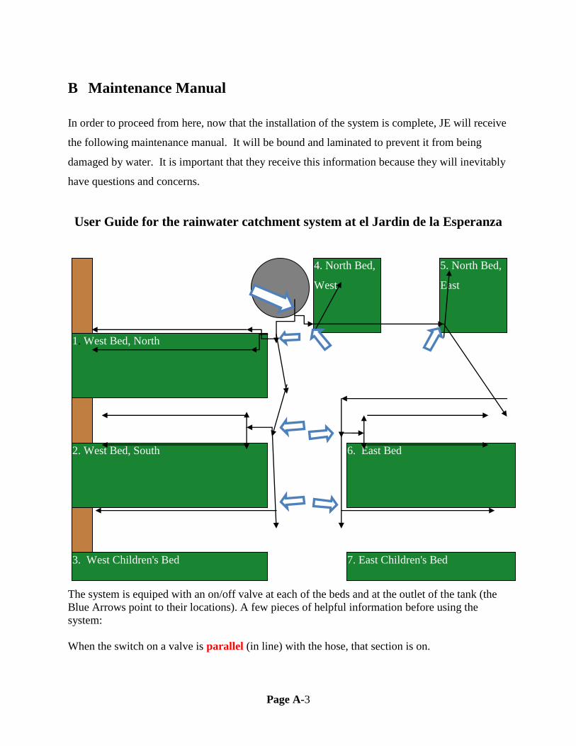
Page A-3
B Maintenance Manual
In order to proceed from here, now that the installation of the system is complete, JE will receive
the following maintenance manual. It will be bound and laminated to prevent it from being
damaged by water. It is important that they receive this information because they will inevitably
have questions and concerns.
User Guide for the rainwater catchment system at el Jardin de la Esperanza
The system is equiped with an on/off valve at each of the beds and at the outlet of the tank (the
Blue Arrows point to their locations). A few pieces of helpful information before using the
system:
When the switch on a valve is parallel (in line) with the hose, that section is on.
3. West Children's Bed 7. East Children's Bed
2. West Bed, South
1. West Bed, North
6. East Bed
4. North Bed,
West
5. North Bed,
East
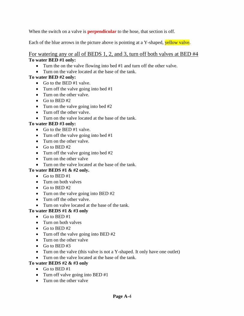
Page A-4
When the switch on a valve is perpendicular to the hose, that section is off.
Each of the blue arrows in the picture above is pointing at a Y-shaped, yellow valve.
For watering any or all of BEDS 1, 2, and 3, turn off both valves at BED #4 To water BED #1 only:
Turn the on the valve flowing into bed #1 and turn off the other valve.
Turn on the valve located at the base of the tank.
To water BED #2 only:
Go to the BED #1 valve.
Turn off the valve going into bed #1
Turn on the other valve.
Go to BED #2
Turn on the valve going into bed #2
Turn off the other valve.
Turn on the valve located at the base of the tank.
To water BED #3 only:
Go to the BED #1 valve.
Turn off the valve going into bed #1
Turn on the other valve.
Go to BED #2
Turn off the valve going into bed #2
Turn on the other valve
Turn on the valve located at the base of the tank.
To water BEDS #1 & #2 only.
Go to BED #1
Turn on both valves
Go to BED #2
Turn on the valve going into BED #2
Turn off the other valve.
Turn on valve located at the base of the tank.
To water BEDS #1 & #3 only
Go to BED #1
Turn on both valves
Go to BED #2
Turn off the valve going into BED #2
Turn on the other valve
Go to BED #3
Turn on the valve (this valve is not a Y-shaped. It only have one outlet)
Turn on the valve located at the base of the tank.
To water BEDS #2 & #3 only
Go to BED #1
Turn off valve going into BED #1
Turn on the other valve
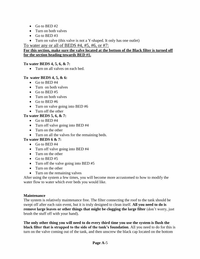
Page A-5
Go to BED #2
Turn on both valves
Go to BED #3
Turn on valve (this valve is not a Y-shaped. It only has one outlet)
To water any or all of BEDS #4, #5, #6, or #7: For this section, make sure the valve located at the bottom of the Black filter is turned off
for the section heading towards BED #1.
To water BEDS 4, 5, 6, & 7:
Turn on all valves on each bed.
To water BEDS 4, 5, & 6:
Go to BED #4
Turn on both valves
Go to BED #5
Turn on both valves
Go to BED #6
Turn on valve going into BED #6
Turn off the other
To water BEDS 5, 6, & 7:
Go to BED #4
Turn off valve going into BED #4
Turn on the other
Turn on all the valves for the remaining beds.
To water BEDS 6 & 7:
Go to BED #4
Turn off valve going into BED #4
Turn on the other
Go to BED #5
Turn off the valve going into BED #5
Turn on the other
Turn on the remaining valves
After using the system a few times, you will become more accustomed to how to modify the
water flow to water which ever beds you would like.
Maintenance
The system is relatively maintenance free. The filter connecting the roof to the tank should be
swept off after each rain event, but it is truly designed to clean itself. All you need to do is
remove large leaves or other things that might be clogging the large filter (don’t worry, just
brush the stuff off with your hand).
The only other thing you will need to do every third time you use the system is flush the
black filter that is strapped to the side of the tank’s foundation. All you need to do for this is
turn on the valve coming out of the tank, and then unscrew the black cap located on the bottom

Page A-6
of the filter. This will flush out all the dirt and small particles out of the filter and essentially
clean it. After 30 seconds or so of flow, just turn off the valve from the bottom of the tank and
then screw the black cap back into place. Then your system is ready for use.
Additionally, inspect your system every few weeks to ensure there are no leaks, cracks, or other
potential problems. Check to make sure the gutters and piping are still securely attached to the
building. Also, observe the drip irrigation system while in use to make sure that no emitter heads
are clogged; these can be changed out easily by simply pulling the emitter head out of the hose
and replacing it with a new one, or cleaned with higher water pressures.

Page B-1
C Final Budget
Final Budget Summary
Income
Expenses
Supplier Amount
Cost Purchaser Vendor Reimbursed
Trinity
Univeristy $1,000
$800.00 Libby Texas Metal Cisterns
Bexar Land
Trust $800
$164.15 Alex Home Depot No
Ferguson
Enterprises $272.32
$17.50 Tyler Longhorn Irrigation
Vulcan
Materials $159
$20.02 Tyler Longhorn Irrigation
$13.76 Philip Truevalue No
Total Working
Budget $2,231.32
$267.86 Alex Home Depot
$28.00 Tyler Home Depot
$45.00 Libby Home Depot No
$11.38 Alex Home Depot
$20.03 Tyler Truevalue
$28.00 Tyler Fergusons
$55.00 Dario Home Depot
$162.66 Philip Home Depot
$70.29 Philip Home Depot
$60.27 Philip Truevalue
$35.43 Libby Home Depot No
$13.25 Philip Home Depot No
$17.00 Dario Truevalue No
$272.32 Libby Fergusons
$159.00 Libby Vulcan Materials
$2,260.92 Total Purchases
Total Budget
Budget
Remaining
$2,231.32 ($29.60)
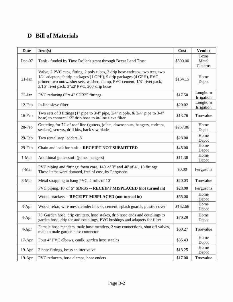
Page B-2
D Bill of Materials
Date Item(s) Cost Vendor
Dec-07 Tank - funded by Time Dollar's grant through Bexar Land Trust $800.00
Texas
Metal
Cisterns
21-Jan
Valve, 2 PVC caps, fitting, 2 poly tubes, 3 drip hose endcaps, two tees, two
1/2" adapters, 9 drip packages (1 GPH), 9 drip packages (4 GPH), PVC
primer, two nut/washer sets, washer, clamp, PVC cement, 1/8" rivet pack,
3/16" rivet pack, 3"x2' PVC, 200' drip hose
$164.15 Home
Depot
23-Jan PVC reducing 6" x 4" SDR35 fittings $17.50 Longhorn
Irrigation
12-Feb In-line sieve filter $20.02 Longhorn
Irrigation
16-Feb Two sets of 3 fittings (1" pipe to 3/4" pipe, 3/4" nipple, & 3/4" pipe to 3/4"
hose) to connect 1/2" drip hose to in-line sieve filter $13.76 Truevalue
28-Feb Guttering for 72' of roof line (gutters, joints, downspouts, hangers, endcaps,
sealant), screws, drill bits, hack saw blade $267.86
Home
Depot
29-Feb Two rental step ladders, 8' $28.00 Home
Depot
29-Feb Chain and lock for tank -- RECEIPT NOT SUBMITTED $45.00 Home
Depot
1-Mar Additional gutter stuff (joints, hangers) $11.38 Home
Depot
7-Mar PVC piping and fittings: foam core, 140' of 3" and 40' of 4", 18 fittings
These items were donated, free of cost, by Fergusons $0.00 Fergusons
8-Mar Metal strapping to hang PVC, 4 rolls of 10' $20.03 Truevalue
PVC piping, 10' of 6" SDR35 -- RECEIPT MISPLACED (not turned in) $28.00 Fergusons
Wood, brackets -- RECEIPT MISPLACED (not turned in) $55.00 Home
Depot
3-Apr Wood, rebar, wire mesh, cinder blocks, cement, splash guards, plastic cover $162.66 Home
Depot
4-Apr 75' Garden hose, drip emitters, hose stakes, drip hose ends and couplings to
garden hose, drip tee and couplings, PVC bushings and adapters for filter $70.29
Home
Depot
4-Apr Female hose menders, male hose menders, 2 way connections, shut off valves,
male to male garden hose connector $60.27 Truevalue
17-Apr Four 4" PVC elbows, caulk, garden hose staples $35.43 Home
Depot
19-Apr 2 hose fittings, brass splitter valve $13.25 Home
Depot
19-Apr PVC reducers, hose clamps, hose enders $17.00 Truevalue