Design of a pipelined radix 4 CORDIC · PDF fileDesign of a pipelined CORDIC processor radix 4...
16
Parallel Computing 19 (1993) 729-744 729 North-Holland PARCO 761 Design of a pipelined CORDIC processor radix 4 J.D. Bruguera a, E. Antelo a and E.L. Zapata b a Dept. Electrdnica. Facultad de Ffsica, Unit. Santiago de Compostela, 15706 Santiago de Compostela, Spain b Dept. Arquitectura de Computadores, Fac. lnformdtica., Univ. Mdlaga, 29013 Mdlaga, Spain Received 6 April 1992 Revised 16 October 1992 Abstract J.D. Bruguera, E. Antelo and E.L. Zapata, Design of a pipelined radix 4 CORDIC processor, Parallel Computing 19 (1993) 729-744. In this work we develop a generalization of the CORDIC algorithm for any radix in three coordinate systems, linear, circular and hyperbolic. We carry out a comparative study between different radixes at the number of additions level, due to the fact that the complexity in additions determines the total hardware associated with the implementation of the algorithm. Radix 4 minimizes the number of additions, therefore we propose a high speed CORDIC processor based on this radix 4. We have developed new criteria for the vectorization and rotation modes and we introduce a new technique for the compensation of a non-constant scale factor, multifactor compensation. The processor we propose is of a general and pipelined character and uses redundant arithmetic (signed digit) in order to reduce the delay in each stage, parallelizing the operation of the adders using a competititive implementation (reduction of the number of stages) with respect to radix 2 implementations which have recently appeared in the literature. Keywords. Digital signal processing; CORDIC algorithm; redundant arithmetic; signed-digit adders; pipelining. I. Introduction The CORDIC algorithm (COordinate Rotation Digital Computer), was introduced in 1959 by Voider [19]. In 1971 Walther [20] generalized the algorithm parametrizing it for three different coordinate systems. It is based on the rotation of a vector in a coordinate system which can be linear, circular or hyperbolic. This rotation permits the production of a large number of arithmetic, trigonometric and hyperbolic functions. Its main applications are currently within the field of computational algebra and image processing [10,14]. It is used for matrix inversion, filtering [12], eigenvalue calculations [1], SVD algorithms [5,8,13], orthogonal transforms [2,3,22], graphic applications [21], simulations and funtions generators [9,17]. The CORDIC is an iterative algorithm which has traditionally been implemented so that all the iterations were executed in the same hardware. Each iteration is carried out only by means of addition/subtraction and shift operations. It is also necessary to have a ROM Correspondence to: J.D. Bruguera, Dept. Electr6nica. Facultad de Fisica, Univ. Santiago de Compostela, Spain. Email: [email protected] This work was supported by the Ministry of Education and Science (CICYT) of Spain under contract TIC92-0942-C03 and Xunta de Galicia XUGA-20601A91. 0167-8191/93/$06.00 © 1993 - Elsevier Science Publishers B.V. All rights reserved
Transcript of Design of a pipelined radix 4 CORDIC · PDF fileDesign of a pipelined CORDIC processor radix 4...

Parallel Computing 19 (1993) 729-744 729 North-Holland
PARCO 761
Design of a pipelined CORDIC processor
radix 4
J.D. B r u g u e r a a, E. A n t e l o a and E.L. Z a p a t a b
a Dept. Electrdnica. Facultad de Ffsica, Unit. Santiago de Compostela, 15706 Santiago de Compostela, Spain b Dept. Arquitectura de Computadores, Fac. lnformdtica., Univ. Mdlaga, 29013 Mdlaga, Spain
Received 6 April 1992 Revised 16 October 1992
Abstract
J.D. Bruguera, E. Antelo and E.L. Zapata, Design of a pipelined radix 4 CORDIC processor, Parallel Computing 19 (1993) 729-744.
In this work we develop a generalization of the CORDIC algorithm for any radix in three coordinate systems, linear, circular and hyperbolic. We carry out a comparative study between different radixes at the number of additions level, due to the fact that the complexity in additions determines the total hardware associated with the implementation of the algorithm. Radix 4 minimizes the number of additions, therefore we propose a high speed CORDIC processor based on this radix 4. We have developed new criteria for the vectorization and rotation modes and we introduce a new technique for the compensation of a non-constant scale factor, multifactor compensation. The processor we propose is of a general and pipelined character and uses redundant arithmetic (signed digit) in order to reduce the delay in each stage, parallelizing the operation of the adders using a competititive implementation (reduction of the number of stages) with respect to radix 2 implementations which have recently appeared in the literature.
Keywords. Digital signal processing; CORDIC algorithm; redundant arithmetic; signed-digit adders; pipelining.
I. Introduction
The CORDIC algorithm (COordinate Rotation Digital Computer), was introduced in 1959 by Voider [19]. In 1971 Walther [20] generalized the algorithm parametrizing it for three different coordinate systems. It is based on the rotation of a vector in a coordinate system which can be linear, circular or hyperbolic. This rotation permits the production of a large number of arithmetic, trigonometric and hyperbolic functions. Its main applications are currently within the field of computational algebra and image processing [10,14]. It is used for matrix inversion, filtering [12], eigenvalue calculations [1], SVD algorithms [5,8,13], orthogonal transforms [2,3,22], graphic applications [21], simulations and funtions generators [9,17].
The CORDIC is an iterative algorithm which has traditionally been implemented so that all the iterations were executed in the same hardware. Each iteration is carried out only by means of addition/subtraction and shift operations. It is also necessary to have a ROM
Correspondence to: J.D. Bruguera, Dept. Electr6nica. Facultad de Fisica, Univ. Santiago de Compostela, Spain. Email: [email protected] This work was supported by the Ministry of Education and Science (CICYT) of Spain under contract TIC92-0942-C03 and Xunta de Galicia XUGA-20601A91.
0167-8191/93/$06.00 © 1993 - Elsevier Science Publishers B.V. All rights reserved
730 J.D. Bruguera et al.
memory for storing constants. Due to its iterative nature, the traditional implementation is very slow for high speed computation [5,9]. More recent implementations have introduced the concept of pipelining. The advances in VLSI technology have made this implementations possible, becoming a competitive element for high speed computations [3,11,12,14,21]. The speed of the pipelined CORDIC processor can still be improved by means of the introduction of redundant arithmetic, substituting the conventional adders by carry save [3,8,15] or signed digit adders [13,17,21]. Another type of implementations of the CORDIC algorithm make use of on-line arithmetic [8,13]. These implementations overlay the input and the output of data with the calculation, reducing this way the communications bandwidth of the circuit. In some specific applications (FFT, FCT, etc.), the rotation angles are known a priori, and this permits the design of application specific CORDIC processors. The presentation of the angle in decomposed manner permits the elimination of the hardware associated with iteration z, because it is not necessary to accumulate this angle [2,3,8].
The CORDIC processors proposed in the literature make use of the radix 2 CORDIC algorithm. That is, the rotation angle is decomposed as a sum of powers of two. In this work we generalize the CORDIC algorithm to any radix (power of 2) and present the design of a general application radix 4 pipelined CORDIC rotator. Radix 4 permits the reduction of the number of microrotations. The processor incorporates signed digit redundant arithmetic which drastically reduces the delays in each stage. This delay does not depend on the precision.
The paper is structured in the following way. In Section 2 we describe the radix 2 CORDIC algorithm. In Section 3 generalize the CORDIC algorithm to any radix, presenting general equations. We perform a comparative study between the different radix in order to obtain which is the most adequate in terms of the reduction of hardware complexity. As radix 4 is the optimal, in Section 4 we present the whole algorithm for radix 4 in its rotation and vectorization modes. We propose an architecture for the CORDIC processor in the rotation mode for the three coordinate systems, using redundant arithmetic. We then develop a new technique for the compensation of the scale factor. Finally, in Section 5 we evaluate the architecture we propose and compare it to radix 2 CORDIC processors which have been recently proposed.
2. The radix 2 CORDIC algorithm
The radix 2 CORDIC algorithm [19,20] consists in rotating a vector in a given coordinate system which we parametrize by m (m = 0 linear, m = 1 circular, m = - 1 hyperbolic). This rotation is decomposed into a series of prefixed elementary rotations, microrotations, whose sense has to be determined. The number of microrotations is determined by the precision of the algorithm. The microrotation angles are given by Oti, m = m - 1 / 2 tan -1 (m 1/2 2-i), with i = 0 ,1 , . . . , n - 1 for circular coordinates and i = 1 . . . . . n - 1 for linear and hyperbolic coordi- nates, where n is the number of bits of the operands (in the case of hyperbolic coordinates some microrotations have to be repeated in order to insure convergence). An initial rotation of r r /2 is necessary for extending the convergence range to [-zr,~r] in circular coordinates. The iterative equations that perform each of these microrotations (it is not a perfect rotation) as a function of the parameter m are
Xi+ l = Xi + m ° ' i Y i 2 - i
Y i+ 1 : Yi -- O'iXi 2 - i (1)
Zi+ 1 = Zi - - o ' i a i ,m

Design of a pipelined radix 4 CORDIC processor 73 l
where cq ~ { + 1, - 1}, is the angle decomposition coefficient, and indicates the sense of each of the microrotations. We have considered that m - t / 2 t a n ( m l / Z ~ a i , m) = ~ 2 -i. The coordi- nates obtained with Eq. (1) are scaled by a constant factor k i = (1 + I~ I m 2-2i) 1/2 with respect to the coordinates corresponding to an authentic microrotation. The total effect is included in the final scale factor, K, which is given by the product of all the factors introduced in each microrotation:
i = n 1 2
K = F I (1 + r n l < [2-2/) 1/2. (2) i = 0
The compensation of the scale factor can be achieved with positive and negative scaling [9], that consists in the introduction of the following operation in specific microrotations
Xi+ 1,2 : (1 + "y2-J)Xi+l,1 (s) Yi+ 1,2 = (1 + y2-J)yi+ 1,1
where xi+l . l and Yi+la are the coordinates of the vector rotated in iteration i and y ~ { -1 , + 1}. The values of j and y are selected in order to make the final scale factor one. Another technique is the repetition of microrotations [1], which consists in the introduction of redundant microrotations in order to force the final scale factor to an integer power of two. The last technique of compensation consists in combining the two previous techniques in order to minimize the number of stages [7].
The CORDIC algorithm has two operation modes, rotation and vectorization. In the rotation mode, we force the final value of the z coordinate to zero, taking or i = sign(zi). With this mode the addition and multiplication (linear coordinates) sine and cosine (circular coordinates) hyperbolic sine and cosine (hyperbolic coordinates) functions are generated. In the vectorization mode, the final value of coordinate y is forced to zero, taking or i = sign(yi). In this mode the CORDIC algorithm generates the subtraction and division (linear coordi- nates), module and tan-1 (circular coordinates), hyperbolic module and tanh-I (hyperbolic coordinates) functions.
The most efficient way of implementing the CORDIC algorithm is the pipelined one, where each microrotation (Eq. (1)) is implemented in a different stage of the pipeline. This way, all the stages of the pipeline have the same complexity. The shift operations to be performed are known a priori for each stage, avoiding the need for variable length shift registers. The implementation of a radix 2 CORDIC processor needs, for a precision of n bits, at least n microrotation stages and approximately n / 4 scale factor compensation stages [5]. If the processor is of a general type, that is, operates in the three coordinate systems, it will be necessary to add stages in order to insure the convergence in hyperbolic coordinates.
3. Generalization of the CORDIC algorithm
In the radix r CORDIC algorithm (where r is a power of two) the microrotation angles have the value ai, m = m -1 /2 tan -1 ( m 1/2 r - i ) and ~ ~ { - r / 2 , . . . , 0 . . . . , r/2}. Among these coefficients we include zero, resulting in a redundant representation. For a given precision, the increase of the radix makes the number of microrotations decrease with respect to radix 2. However, it is necessary to determine which is the radix that minimizes the hardware. When using radix different from 2, the coefficients tr i are different from one and the approximation m -1/2 tan(ml /20" ia i ,m)= ~r~r -i is not valid. In order to obtain the general expression of the

732 .I.D. Bruguera et al.
Table 1 Decomposition of the radix 4 coefficient
(5i (5i , i (5 i , 2
0 +1 -1
+1 __1 0
+2 +1 +1
radix r CORDIC rotations, we will first deduce the radix 4 equations from the radix 2 equations. In an iterative manner we will obtain the CORDIC equations for higher radix.
3.1. Radix 4 CORD1C equations
In radix 4 o- i ~ { + 2, + 1, 0}. This means that for a given microrotation angle a double rotation, a simple rotation or no rotation can be carried out. By means of the decomposition of the radix 4 microrotation into two successive radix 2 microrotations with the same microrotation angle we can obtain the equations of the radix 4 microrotation. In order to do this, we will express the radix 4 coefficient as the sum of two radix 2 redundant decomposition coefficients (zero is included). The relationship between the radix 4 coefficient (tri) and the radix 2 coefficients (cr~,~ and ¢ri, 2) is o" i = O'i, 1 ~- Ovi, 2 (see Table 1). This relationship means that we understand a radix 4 microrotation as the application of two radix 2 microrotations, with the option of carrying them out or not. The radix 4 CORDIC equations obtained are
xi+ l = xi + m( ~ri, a + ¢ri,z)4-iyi - m~.,a~ri,24- Zix i
Y i + l = Yi - (O'i,1 + O ' i , 2 ) 4 - i x i - m ° ' i , l ° ' i , 2 4 - 2 i y i (4)
Z i + 1 = Z i - - (ori, 1 + Ori,2)Oli, m .
With the radix 4 CORDIC equations the convergence is insured despite halving the number of microrotations. The scale factor introduced in each of the microrotations is given by ki = (1 + m I o-/, 114-2i) 1/2" (1 + m I o-i, 214-2i) 1/2. The final scale factor is given by
S - - 1 2
K = I-I (1 +rnl(r/ . , 14-2i) l /2"(l+mltri .214-2i) '/2, (5) i = 0
where S is the number of radix 4 stages. K is not a constant with respect to the decomposi- tion coefficients (~ri, 2 can take the value zero) and it depends on the initial data.
3.2. Radix r CORDIC equations
In order to obtain the radix r CORDIC equations we apply the radix r /2 CORDIC equations twice, expressing the radix r decomposition coefficients as the sum of two radix r / 2 coefficients. Continuing in this manner, we can obtain the general expression for the radix r CORDIC equations
c L , =ci ~ + ~., [sign((ri)]JF(k, j ) m cO'k) ~ r-i'Jc e(k'j) (6) j=l J

Design of a pipelined radix 4 CORDIC processor 733
with i---0, 1,.. c o = x i and cI = Yi, and where
e ( k , j ) = l [ 1 - ( - 1 ) (j+~)]
F(k , j ) = ( - 1) ti/21+jk
( j - e ( j , k) = 1 - I , +
., S - 1, and k = 0, 1; where S is the number of microrotations in radix r. Also
(7)
In Eq. (6) we encompass the two CORDIC equations corresponding to the x and y coordinates. Each one of them is a pt-lynomial of degree r/2 in the term r -i. The final scale factor is given by the following expression
S r - - - 1 2
K = 1-I 1--I [1 q-m:o'i,plr-2i] 1/2 (8) i = 0 p = l
= ~.r/2 0.i,p, where ~ri, p c { - 1,0 + 1} and this coefficients satisfy ~r i p = 1 In order to obtain the ,-.umber of microrotations, S, necessary for each radix we must take
into account that the number of iterations is given by the precision of the algorithm and it will be determined by the ~ongest of the right shifts in the CORDIC equations (n - 1 for n bit precision) and that the decomposition coefficients have a maximum value of r/2. Then we can deduce the number of mierorotations
S = [ n - l + l ° g 2 ( r / 2 ) (9)
Going from radix 2 to radix 4 means halving of the number of microrotations. Further increases in the radix give a lesser reduction, and the number of additions increases.
3.3. Comparative analysis
In the pipelined implementation of the CORDIC algorithm, the most costly element in silicon area is the adder, therefore, the number of additions determines in a reliable manner the hardware complexity of the processor. In this analysis we must take into account the additions due to Eq. (6) and additions due to the multiplication by coefficients which are not integer powers of two. These coefficients correspond to a combinatory number and this forces the introduction of further additions in order to carry out the multiplication, However, in a pipelined design, throughout the pipeline there will be terms which exceed the precision of the algorithm, as shifts larger than the word size are performed. This is reflected in the fact that in the iteration being evaluated, part of the addition operations of Eq. (6) do not have to be carried out. Therefore, we must calculate an effective number of the additions mentioned.
In Fig. 1 we represent the number of effective additions versus the radix for two typical precisions, 16 and 24 bits, and for the three coordinate systems. In this analysis we have not taken into account the z coordinate, neither the compensation of the scale factor. For radix 4 a minimum is obtained, with savings of 25% in additions with respect to radix 2 in circular and hyperbolic coordinates and of 50% in the case of linear coordinates. Further increases in the radix make the number of additions grow, due to the multiplications times the coefficients. From the results obtained we can deduce that radix 4 is the optimum one as it minimizes the number of microrotations and the number of adders.

734 J.D. Bruguera et al.
number of eFFective adders 270
225
IBO
135
90
45
n:24
n=16
n:24 n:16
t:irc u[l~r on@ hyperbol ic
coord ina tes
~.ifleQr coord;nat es
I I I I ) r
4 8 12 16
Fig. 1. Number of effective additions in the CORDIC algorithm for different radix, coordinate systems and precisions.
4. Radix 4 CORDIC processor
In this section we will present the radix 4 CORDIC algorithm for the two modes of operation, vectorization and rotation. In the radix 2 CORDIC algorithm, the criterium for the determination of the sense of the microrotation is simple, as it is determined from the sign of zg (rotation) or Yi (vectorization). In radix 4 this criterium is not enough, because apart from determining the sense of the microrotation, we must determine the multiplication factor 0, 1 or 2 associated with it. The next two lemmas present a criterium for both operation modes, for the radix 4 CORDIC algorithm. They will be demonstrated in Appendix A.
Lemma 1. The convergence o f the radix 4 C O R D I C algorithm in the rotation mode is insured i f we take
0
~ri= sign(zi)
2. s ign(z i )
[3i i f [ZiJ < - ~
[3i i f ~ ~ l z i l < - -
313i i f Jz i[ > - -
- 2
313i (10) 2
insured i f we take
0 i f [ YiJ < [3i "X_______~i 2
[3i " X i = - - < l y i l < - - ~ri sign(yi) i f 2 - 2
3" [3i " Xi 2" sign(yi) i f [ y i J >_
where [30 = 2 - l and fli = 4 - i for 1 < i <_ S - 1.
3 • [ 3 i " X i (11)
where [3 0 = 2-1 and [3i = 4- i for 1 ~ i <_ S - 1.
Lemma 2. The convergence o f the radix 4 C O R D I C algorithm in the vectorization mode is

Design of a pipelined radix 4 CORDIC processor
Table 2 Microrotation angles for the three coordinate systems
735
Microrotation Angle (Circular) Angle (Hyperbolic) Angle (Linear)
0 0.463647609 0.549306144 0.500000000
1 0.244978663 0.255'41281 I 0.250000000
2 0.062418810 0.062581571 0.062500000
3 0.015623729 0.015626271 0.001562500
4 0.003906230 0.003906269 0.003906250
5 0.000976562 0.000q76562 0.000976562
6 0.000244140 0.000244140 0.000244140
7 0.000061035 ( 1 ) 610~,5 0.000061035
8 0.000015258 0.0(10015258 0.000015258
9 0.000003814 0.00(X)03814 0.000003814
10 0.000000953 0.000000953 0.000000953
11 0.000000238 0.000000238 0.000000238
Also, with this criterium, in hyperbolic coordinates it is not necessary to introduce repetition of microrotations in order to insure the convergence. This way, the number of stages of the processor is smaller. In Table 2 we present the final microrotation angles for the three coordinate systems. We have selected t an - l (2 -1 ) as the first microrotation angle in circular coordinates, instead t an- ~(4-°), in order to insure the convergence with the criterium for radix 4 rotation mode expressed in Lemma 1. For the rotation mode, the comparison points are known a priori, and they are simple powers of two. In this way, this criterium can be easily implemented. However, for the vectorization mode, the comparison points are not known a priori (they depend on the value of the x coordinate in each stage) the comparator can be complex, with respect to the implementation of the criterium for radix 2 vectorization mode. For this reason we will only consider the rotation mode.
4.1. Implementation of the rotation criterium
In order to reduce the delay in each stage, we will include signed digit redundant arithmetic in our design [4,16]. This way we parallelize the adders and reduce the delay making it independent from the precision. Expression (10) is a generic formulation of the rotation criterium for the radix 4 CORDIC algorithm. In this section we are going to particularize this criterium for the case of radix 2 signed digit redundant arithmetic. A number x is represented as ( x v . . . x o, X l . . . x i . . . x n) where xi belongs to the set {1, 0, -1}. In the first place we must study the limits of the z coordinate as the microrotations are produced. The convergence condition for the radix 4 CORDIC algorithm in iteration i for any of the coordinate systems is given by expression
n/2-1
[zil <_2" ~ ai,m < 2 -2i+2. (12) j=i

736 ZD. Bruguera et al.
In iteration i, the most significant digit of the z coordinate will be at most in the 2 i - 1 positior On the other hand, from the criterium obtained in expression (10), the coefficient cr~ is zero i) I z~l < 2-2i /2 = 4-~/2. In this case the most significant digit of the z coordinate in iteration i is at most in the 2i + 2 position. On the other hand, in iteration i we have to estimate the value of the z coordinate with a precision of 2 -(2i+3), which is sufficient in order to guarantee the convergence. Therefore, we only need to evaluate five digits in each iteration. That is, we must consider the digits 2i - 1, 2i, 2i + 1, 2i + 2 and 2i + 3. We define the truncation operator, r ( ), over a number x in the radix 2 signed digit fractional representation as
T ( X p . . . X o , X l . . . X n ) = X _ p . . . X O. (13)
Taking into account expression (12), it is easy to prove that by shifting the value of the z coordinate in iteration i, 2i + 3 positions to the left, and cutting off its value it verifies
r (2 2i+3" Iz i l ) _<23"3. (14)
As the most significant digit of the z coordinate in iteration i is 2i - 1, we can take as the cut off value of the z coordinate a five digit integer as follows
g(2 2i+3" ]Zi l) ~ [Z2i- ' , Z2i, Z2i+l, Z2i+2, Z2i+3 ]. (15)
This integer, due to expression (14) can only take values { - 2 4 , - 2 3 . . . . . - 2 , - 1 , 0, 1 . . . . . 23, 24}. Therefore, by testing the value of these five digits in each stage and comparing it to the values of this set we can determine the value of cry. In order to determine the sign of the coefficient ~r i it is sufficient to detect the sign of the five digits of the z coordinate we consider in each iteration. For calculating the magnitude of ~r i we check the value of the integer expressed in (15). In this way, the criterium for radix 4 rotation mode in signed digit arithmetic is
0 if - 3 _< [ z2i_ 1, z2i, z2i+ 1, z2i+2, Z2i+3] -~< 3
1 if 4_< [Z2i_l, Z2i , Z2i+l , Z2i+2 , Z2i+3 ] _< 11
or,.= - 1 if -11_<[z2i_1, z2i , zzi+l, z2i+2, Z2i+3]~ --4 (16)
2 if 12 _< [Z2i_I, Z2i , Z2i+l , Z2i+2 , Z2i+3 ] _~< 24
2 if --24_<[Z2i_1, Z2i , Z2i+I , Z2i+2 , Z2i+3]_~< --12.
Figure 2 shows the structure corresponding to a stage of the z coordinate where we include the criterium for the rotation mode. The SIGN block is a combinational circuit which detects the sign of the integer number made up by the five most significant digits of the z coordinate. The M A G N I T block is a combinational circuit that calculates the magnitude of the ~i coefficient. The logic operation of this circuit is shown in Table 3. The current value of the z coordinate, z,+ 1, is obtained from an addi t ion/subtract ion of z i and the microrotation angle obtained from the 3 : 1 multiplexors. In the addition, one of the operandi (the microrotation angle) is expressed in two's complement and the other in radix 2 signed digit. With this, the complexity of the resulting adder is similar to that of the carry ripple [18]. As we show in Fig. 2, in the output of the adder we must introduce another block, we call it COMPACT, whose mission is to insure the condition given in expression (12), with respect to the most significant digit of z in each microrotation. In the addi t ion/subtract ion operation over the z coordinate in iteration i - 1 there can be significant digits up to posi t ion 2i - 3, due to the redundant representation used [17]. If we consider the set of digits 2i - 3, 2i - 2 and 2i - 1 as integer, we know by condition (12) that their value belongs to the set {-1,0,1}. Therefore, the block C O M P A C T eliminates this redundance.
The implementation of the x and y coordinates need 4 adders, two for each of the coordinates (see Fig. 3). In each of these stages we have two rows of 2 : 1 multiplexors, where

Design of a pipelined radix 4 CORDIC processor 737
Z21-1 = * = Z2i+3
I Sl MA [ SIGN J - ~ MAC
I s i g n
eL I
m;croro~at;on angle
~r
I */- (1 CtClO r
Z + l
Fig. 2. Implementation of the z coordinate in radix 4.
Zl
we carry out the multiplication of the coefficients times the shifted value of the coordinate, which corresponds to the third term in Eq. (4). In the two rows of 3:1 multiplexors we perform a similar multiplication, but corresponding to the second term of Eq. (4). However, in the last n/4 stages of the processor, the complexity of the microrotation is reduced. The two higher adders and their associated multiplexors disappear as one of terms of these adders exceeds the precision of the algorithm and is therefore considered null. The adders used in the implementation of the x and y coordinates are signed digit [21]. The total number of microrotations of the algorithm is n/2, with the structure shown in Figs. 2 and 3. The number of adders is n/2 for the z coordinate an.d 2n - n/2 for the x and y coordinates. This architecture is the same for the three coordinate systems.
4.2. Compensation of the scale factor
In the radix 4 CORDIC algorithm, the scale factor is not constant with respect to the decomposition coefficients (for circular and hyperbolic coordinates) as they have values in {0, + 1, + 2}, and this is the main disadvantage of radix 4 respect to radix 2. In this section we
Table 3 Logic operation of the MAGNIT circuit
a b ° i , 1 o i , 2
0 0 +1 -1
0 1 _+1 0 < 3 . 4 - ' / 2
1 0 +1 +1 Iz~l> 3" 4 - ' / 2

738 J.D. Bruguera et al.
x I
÷
L
[ y J
-- +
I X , . t Y ~.I
Fig. 3. Implementation of the x and y coordinates in radix 4.
Control
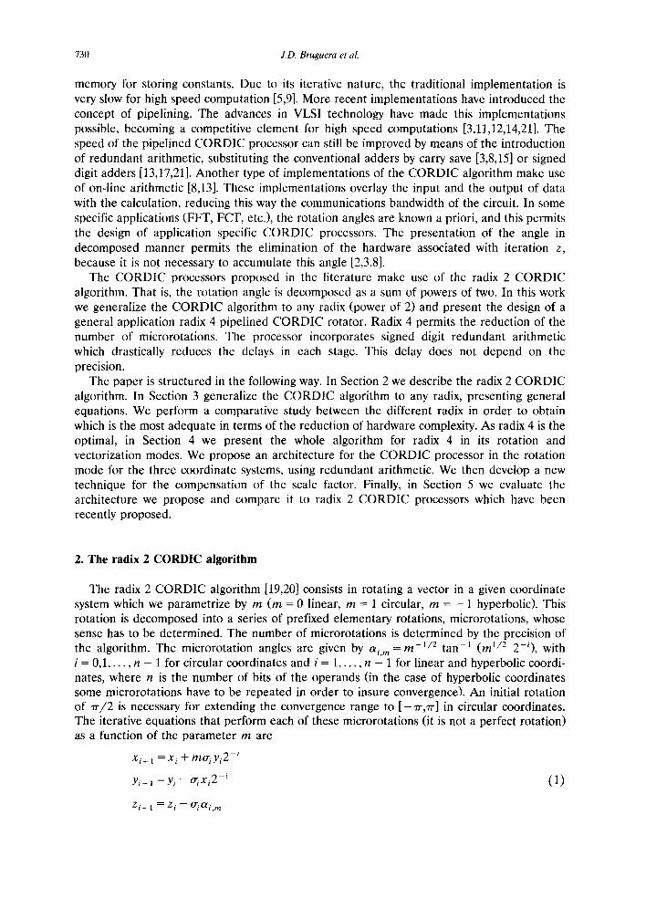
introduce a new technique for the compensation of a non constant scale factor, the multifac- tor compensation with scaling. This technique is based on the calculation of all the possible scale factors. The compensation is obtained by scaling (see Eq. (3)) for each of these factors. The general architecture of a muW*ifactor compensation stage (for a single coordinate) is shown in Fig. 4. It consists of an adder and k + 1 2 : 1 multiplexor stages (where k = [log2(n)], being n the precision of the algorithm). In these multiplexor stages, the wired shifts corresponding to each multifactor compensation stage are carried ~ ,t, and accepting the possibility that the stage does not contribute to the scaling (adds the value zero). This way, with k + 1 bits we can control the shift to be performed in each stage or add the value zero. The complete architecture is made up of q stages similar to the one shown in Fig. 4 (where q is the maximum number of scaling stages needed by the scale factors to be compensated), and by a control ROM memory, which contains the signals which program the shifts in the 2 : 1 multiplexors and control the adders in each stage. The control ROM memory has as many words as possible scale factors to be compensated. This word size is estimated at a maximum value of (k + 2). q.
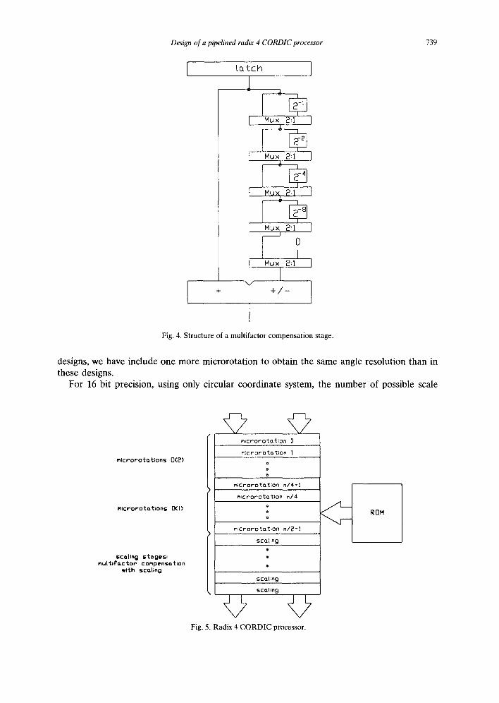
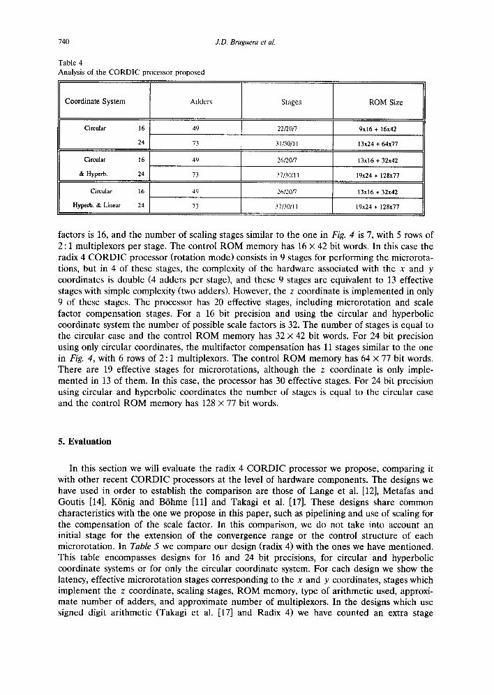
In Fig. 5 we present the structure of the CORDIC processor we propose. The first microrotations are of double complexity (from i = 0 to i = n / 4 - 1), followed by the microro- tations of simple complexity (from i = n / 4 to i = n / 2 - 1). The last stages correspond to the variable scale factor compensation. In Table 4 we summarize the features of the radix 4 CORDIC processor proposed for 16 and 24 bit precision using different coordinate systems. In the first column we specify the number of adders, in the stages column we specify the required number of stages for a radix 2 CORDIC processor [11], the number of effective stages for the radix 4 CORDIC processor (a double complexity stage is considered as two effective stages), and the number of stages corresponding to the multifactor compensation with scaling (stages necessary in a radix 2 CORDIC processor/effect ive stages of a radix 4 CORDIC processor/s tages of multifactor compensation with scaling). In the last column we specify the necessary ROM memory. In order to compare our design with other recent
Design of a pipelined radix 4 CORDIC processor 739
I Latch I
i
I Mux 2:1
I--- Mux 2:1
I Mux 24
J Mux 2:1 I
0
I M u x 2:1
v + + / -
Fig. 4. Structure of a multifactor compensat ion stage.
designs, we have include one more microrotation to obtain the same angle resolution than in these designs.
For 16 bit precision, using only circular coordinate system, the number of possible scale
m;crorot~t;ons 0(2)
M;crorot ot;ons 0(I)
scaUn 9 s~cages: mu| t;~'0,ctor" compenso~clon
w;~ch sc~L;ng
mlcrorotation 0
m;cr or O~Ca t;on I
o
o
o
micr oro'to.t ;on n/4-1
mic r or'o t c~'t;on n/4 o
o o
m;crorotation n/2-1
sewing
SCO,(;n 0
scoUng
Fig. 5. Radix 4 C O R D I C processor.
ROM
740
T a b l e 4
Ana lys i s o f the C O R D I C p r o c e s s o r p r o p o s e d
J.D. Bruguera et al.
Coordinate System
Circular 16
24
Adders
49
73
Stages
22/20/7
31/30/11
R O M Size
9x16 + 16x42
13x24 + 64x77
Circular 16 49 26/2.0/7 13x16 + 32x42
& Hyperb. 24 73 37/30/11 1%24 + 128x77
Circular 16 49 26/2.0/7 13x16 + 32x42
Hyperb. & Linear 24 73 37/30/11 19x24 + 128x77
factors is 16, and the number of scaling stages similar to the one in Fig. 4 is 7, with 5 rows of 2 : 1 multiplexors per stage. The control ROM memory has 16 x 42 bit words. In this case the radix 4 CORDIC processor (rotation mode) consists in 9 stages for performing the microrota- tions, but in 4 of these stages, the complexity of the hardware associated with the x and y coordinates is double (4 adders per stage), and these 9 stages are equivalent to 13 effective stages with simple complexity (two adders). However, the z coordinate is implemented in only 9 of these stages. The processor has 20 effective stages, including microrotation and scale factor compensation stages. For a 16 bit precision and using the circular and hyperbolic coordinate system the number of possible scale factors is 32. The number of stages is equal to the circular case and the control ROM memory has 32 x 42 bit words. For 24 bit precision using only circular coordinates, the multifactor compensation has 11 stages similar to the one in Fig. 4, with 6 rows of 2 : 1 multiplexors. The control ROM memory has 64 x 77 bit words. There are 19 effective stages for microrotations, although the z coordinate is only imple- mented in 13 of them. In this case, the processor has 30 effective stages. For 24 bit precision using circular and hyperbolic coordinates the number of stages is equal to the circular case and the control ROM memory has 128 x 77 bit words.
5. Evaluation
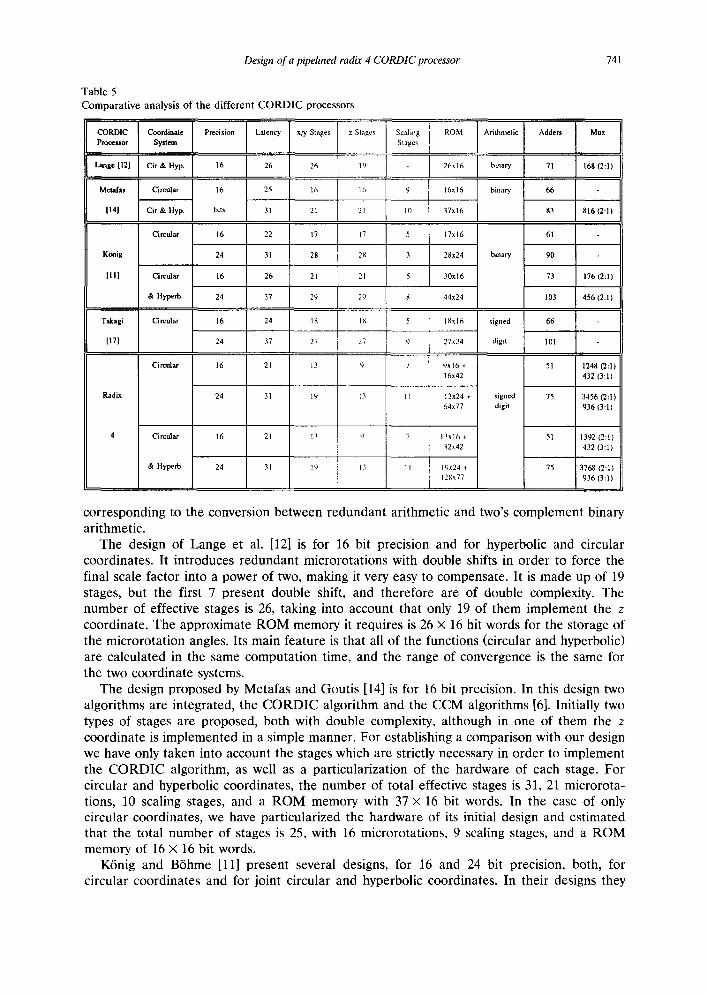
In this section we will evaluate the radix 4 CORDIC processor we propose, comparing it with other recent CORDIC processors at the level of hardware components. The designs we have used in order to establish the comparison are those of Lange et al. [12], Metafas and Goutis [14], K6nig and B6hme [11] and Takagi et al. [17]. These designs share common characteristics with the one we propose in this paper, such as pipelining and use of scaling for the compensation of the scale factor. In this comparison, we do not take into account an initial stage for the extension of the convergence range or the control structure of each microrotation. In Table 5 we compare our design (radix 4) with the ones we have mentioned. This table encompasses designs for 16 and 24 bit precisions, for circular a n d hyperbolic coordinate systems or for only the circular coordinate system. For each design we show the latency, effective microrotation stages corresponding to the x and y coordinates, stages which implement the z coordinate, scaling stages, ROM memory, type of arithmetic used, approxi- mate number of adders, and approximate number of multiplexors. In the designs which use signed digit arithmetic (Takagi et al. [17] and Radix 4) we have counted an extra stage
Design of a pipelined radix 4 CORDIC processor
Table 5 Comparative analysis of the different CORDIC processors
741
Metafas Circular 16 25 16 I 6 9
114] Cir & Hyp. bits 31 21 21 10
Circular 16 22 17 17 5
K6nig 24 31 28 28 3
III1 Circular 16 26 21 21 5
& Hyperb. 24 37 29 29 8
Takagi Circular 16 24 1 ~ I ~ 5
[17] 24 37 27 27 9
Circular 16 21 13 t) 7
Rad~ 24 31 19 13
4 Circular 16 21 13 tl
& Hyperb. 24 3I 19 I~
ROM Arithmetic I Adders I Mux
16x16 binary 66
37x16 83 816 (2:1)
17x16 61
28x24 binary 90
30x16 73 176 (2:1)
44x24 103 456 (2:1)
18xl 6 signed 66
27x24 digit 101
9x16 + 51 1248 (2:1) 16x42 432 (3:1)
11 13x24 + signed 75 3456 (2:1) 64x77 digit 936 (3:1)
7 13x16 + 5I 1392 (2:1) ~2x42 432 (3:1)
I I 19x24 + 75 3768 (2:1) 128x77 936 (3:1)
corresponding to the conversion between redundant arithmetic and two's complement binary arithmetic.
The design of Lange et al. [12] is for 16 bit precision and for hyperbolic and circular coordinates. It introduces redundant microrotations with double shifts in order to force the final scale factor into a power of two, making it very easy to compensate. It is made up of 19 stages, but the first 7 present double shift, and therefore are of double complexity. The number of effective stages is 26, taking into account that only 19 of them implement the z coordinate. The approximate ROM memory it requires is 26 x 16 hit words for the storage of the microrotation angles. Its main feature is that all of the functions (circular and hyperbolic) are calculated in the same computation time, and the range of convergence is the same for the two coordinate systems.
The design proposed by Metafas and Goutis [14] is for 16 bit precision. In this design two algorithms are integrated, the CORDIC algorithm and the CCM algorithms [6]. Initially two types of stages are proposed, both with double complexity, although in one of them the z coordinate is implemented in a simple manner. For establishing a comparison with our design we have only taken into account the stages which are strictly necessary in order to implement the CORDIC algorithm, as well as a particularization of the hardware of each stage. For circular and hyperbolic coordinates, the number of total effective stages is 31, 21 microrota- tions, 10 scaling stages, and a ROM memory with 37 × 16 bit words. In the case of only circular coordinates, we have particularized the hardware of its initial design and estimated that the total number of stages is 25, with 16 microrotations, 9 scaling stages, and a ROM memory of 16 x 16 bit words.
K6nig and B6hme [11] present several designs, for 16 and 24 bit precision, both, for circular coordinates and for joint circular and hyperbolic coordinates. In their designs they

742 J.D. Bruguera et al.
avoid double shifts and compensate the scale factor with scaling and repetitions. By means of certain convergence restrictions they try to find a set of coefficients which minimize the total number of stages. For 16 bit precision in circular and hyperbolic coordinates it has a total of 26 stages, 21 microrotations, 5 scaling stages, and a ROM memory with 30 X 16 bit words. In the case of only using circular coordinates, the total number of stages is 22, (17 + 5) and a ROM memory with 17 x 16 bit words. For 24 bit precision in circular and hyperbolic coordinates, the total number of stages is 37, (29 + 8) and a ROM memory with 44 x 24 bit words. For 24 bit precision in circular and hyperbolic coordinates, the total number of stages is 37, (29 + 8) and a ROM memory with 44 x 24 bit words. For the case of only circular coordinates, the number of total stages is 31 (28 + 3).
Takagi et al. [17] propose a CORDIC rotator in circular coordinates, for the calculation of sine and cosine trigonometric functions. It uses radix 2 signed digit redundant arithmetic like our design. In order to insure a constant scale factor, they introduce two techniques, double rotation method and the correction rotation method. The double rotation method is based on performing each microrotation as two successive microrotations of half the angle with coefficients in the set { - 1, + 1}. This way, in all the microrotations (double) a scale factor is introduced independently from the fact that the microrotation is carried out or not. This way, they manage to make the scale factor constant. The correction rotation method consists in only using the values + 1 and - 1 for the coefficient ~r~ despite using redundant arithmetic. This causes that after a certain number of microrotations, there has to be an extra correction microrotation in order to insure the convergence. This technique guarantees a constant scale factor. The optimal solution is obtained by combining both techniques. Thus they propose the use of the correction rotation method in the first half of the stages and the double rotation method in the second half. The algorithm they initially propose is for the calculation of the trigonometric functions and the scale factor is compensated by introducing the data scaled. Another aspect to be taken into account is that the range of the input angles is limited to - ~ - / 4 ~< 0 < ~-/4. In order to establish a comparison with this design and the one propose in this paper, we are going to consider it as a rotator in circular coordinates. This means that the scale factor must be compensated with the usual techniques for the compensation.
The use of signed digit arithmetic in the radix 4 CORDIC processor proposed in this paper permits the parallelization of the operation of the adders, reducing the delay of each microrotation with respect to implementations which use non redundant binary arithmetic. By means of the introduction of radix 4 in all the CORDIC microrotations we significantly reduce the number of adders and the latency (effective stages) with respect to the other implementations in the table. This difference is more pronounced when circular and hyper- bolic coordinates are used together, as in radix 2 solutions the use of hyperbolic coordinates makes the introduction of microrotation repetitions necessary in order to insure convergence. On the other hand, the compensation of non-constant scale factor, by means of the technique developed in this work, permits the elimination of the main limitation of the generalized application of radix 4 to the design of high speed CORDIC processors with the cost of increasing the area of ROM memory and multiplexors. Finally, the generalization of the CORDIC algorithm to radix 4, the development of a technique for the compensation of a non constant scale factor, and the use of redundant arithmetic, has allowed us to develop a new general application CORDIC processor architecture which optimizes characteristics of previ- ous designs.
Appendix A
Lemma 1. The convergence of the radix 4 CORDIC algorithm in the rotation mode is insured if we select the ~ coefficient with the criterium expressed in (10).

Design of a pipelined radix 4 CORDIC processor 743
Proof. The convergence condit ion in the radix 4 C O R D I C algor i thm is [ Z n / 2 ] <_~ AZ m n, with Azm, n = m -1/2 t a n - t ( m ~ / 2 2 - " + l ) , for n bit precision. Let a i = m - 1 / 2 tan-~(ml/2/3i), 'Ci, m = 2 .~'n/2-~j=i ag, m+Azmn,, / 3 o = 2 - ~ a n d / 3 ~ = 4 -g for l < i < n / 2 - 1 . A t t h e f i r s t t i m e , _ to demons t r a t e by induct ion over i that I z~+~ I < Cg+l,m, for i = 0 . . . . . n / 2 -- 2, and then we will demons t r a t e that I zn/21 _< aZm,n. We have to take into account that zi+ ~ = z , - ~.ai, m and I z01 < Co,.,. For i = 0, we have three possible different cases
(i) If I zol </3o /2 , then I~ro I = 0 and I Zl I < / 3 0 / 2 < Cl,m. (ii) I f 3/30/2 > I z01 > /30 /2 , then I(r 0 I = 1 and I zl [ < (2m + 1)/30/2 - mao, m < Cl,.,.
(iii) If C o , m ~_~ I z01 >-- 3/30/2, then [ao [ = 2 and I z 1 I < Co,., - 2cr0,m < CI , m. In all cases the condi t ion ] z I I < Cl,m is satisfied. Now we suppose that ] zil < Ci,m, then,
as before , we have three possible cases (i) If Izgl </3 i / 2 , then I,ril = 0 and Izi+~[ </3i /2 .
(ii) If 3/3z/2 > I zil >-/3i/2, then l ai I = 1 and I zi+ll < (2m + 1)/3i/2 - mcci, m. (iii) If Ci, m >_ I zgl >__ 3/3i/2, then Io- i I = 2 and I z~+a I < Ci+~,m. I f we take into account t ha t / 3g /2 < (2m + 1)/3,./2 - mai , . , < C~+~,m, then in all of the cases
I zi+ 11 < Ci+l,",. In o rder to obta in the r ema inde r angle we taken i = n / 2 - 1 (last radix 4 microrota t ion) . In this par t icular case I Zn/2_ ~ I <-- Cn/2- ~ r n = 2a n/2_ t ., + Az . , n. On the o ther hand we can express m 1/2 t a n - t (ml /22 2i) __ 2=2i ' m 2 - 6 i / 3 + ~.., for f > n / 2 - 2, we can approx imate m - ~ / e tan ~(m~/22 -2i) - - 2 -2~ for n bit precision. Again we have three possible cases:
(i) If I z n / 2 _ l l < 2 - n + 2 / 2 , then Io'n/2_l I = 0 and ]zn/21 < 2 - n + l = A Z m , n . (ii) If 3 " 2 - n + 2 / 2 > Iz~/2_11 > 2 - n + 2 / 2 , then I~rn /2_~l= l and Izn/21 < 2 - n + l =
A Zm, n.
(iii) If Cn/2_l,m > I z , / 2 - ~ l > 3 " 2 - n + 2 / 2 , then I ,~/2-~ I = 2 and Iz~/2l <--aZm,n. For all of the cases I z , /21 < A z . . . . and the convergence in insured. []
Lemma 2. The convergence o f the radix 4 CORDIC algorithm in the uectorization mode is insured if we select the o" i coefficient with the criterium expressed in (11).
Proof. In radix 4 the convergence condi t ion can be expressed as t a n - l ( y n / 2 / X n / 2 ) < m -1/2 tan 1(ml /22-"+1) . For the vector iza t ion mode , we can t rans form the y coord ina te equa t ion as Yi÷l = [ (Y i / /X i )" ( l -- mtriAtri,2/3~) - (o'/, 1 + 0"/,2)/3 i] "x i. I f we identify Yi/Xi in this equa t ion with z i in the equat ion cor responding to the rota t ion mode , and taking into account that xi<_xi+ t, then we can obta in in a similar way to the previous l e m m a t h a t l Yn/2l <- 2 n+lxn/2" For the vector iza t ion m o d e we can impose the condit ion l yil_< Ixgl < 1, and
n+l 1 then I y,/~_41 _< 2 - - v~-. In this case we can approx imate t a n - (yn/L,-~/x n/z") = Y~/2/X~/2 -- < I/2 1 1/2 n+ l 2 - n + l = m - t a n - ( m 2 ), and the t e m m a is proved. []
References
[1] H.M. Ahmed, J.M. Delosme and M. Morf, Highly concurrent computing structures for matrix arithmetic and signal processing, IEEE Cornput. (1982) 65-82.
[2] F. Argiiello, Application specific array processor for fast orthogonal transforms (in Spanish), Ph. D. Dissertation, Univ. Santiago de Compostela (Spain), 1992.
[3] F. Argiiello, J.D. Bruguera, R. Doallo, T. Lang and E.L. Zapata, CORDIC based application specific processor for orthogonal transforms (submitted for publication).
[4] A. Avizienis, Signed-digit number representations for fast parallel arithmetic, IRE Trans. Electron. Comput. EC-10 (1961) 389-400.
[5] J.R. Cavallaro and F.T. Luk, CORDIC arithmetic for an SVD processor, J. Parallel and Distributed Comput. 5 (1988) 271-290.

744 J.D. Bruguera et al.
[6] R.C. Chen, Automatic computation of exponentials, logarithms, ratios and square roots, IBMJ. Res. Dev. (1972) 380-388.
[7] J.M. Delosme, VLSI implementation of rotations in pseudo Euclidean spaces, IEEE Internat. Conf. Acoustics, Speech, and Signal Processing, Boston, MA 2 (1983) 927-930.
[8] M.D. Ercegovac and T. Lang, Redundant and on-line CORDIC: Application to matrix triangularization and SVD, IEEE Trans. Comput. C-39 (6) (1990) 725-740.
[9] G.L. Haviland and A.A. Tuszynski, A CORDIC arithmetic processor chip, IEEE Trans. Comput. C-29 (2) (1980) 68-79.
[10] Y.H. Hen, CORDIC-based VLSI architecture for digital signal processing, IEEE Signal Processing Mag. 7 (1992) 16-35.
[11] D. K6nig and J.F. B6hme, Optimizing the CORDIC algorithm for processors with pipeline architecture, Signal Processing I1... Theories and Applications (Elsevier Science, Amsterdam, 1990) 1391-1394.
[12] A.A. de Lange and E.F. Deprettere, Design and implementation of a floating-point quasi systolic general purpose CORDIC rotator for high-rate parallel data and signal processing, Proc. lOth Syrup. on Computer Arithmetic (1991) 272-281.
[13] J. Lee and T. Lang, SVD by constant-factor-redundant-CORDIC, Proc. lOth Symp. on Computer Arithmetic (1991) 264-271.
[14] D.E. Metafas and C.E. Goutis, A DSP processor with a powerful set of elementary arithmetic operations based on CORDIC and CCM algorithms, Microprocessing and Microprogramming 30 (1990) 51-58.
[15] T.G. Noll, Carry-save architectures for high-speed digital signal processing, J. FLSI Signal Process. 3 (1 & 2) (1991) 121-140.
[16] B. Parhami, Carry-free addition of recorded binary signed-digit Numbers, IEEE Trans. Comput. 37 (11) (1988) 1470-1476.
[17] N. Takagi, T. Asada and S. Yajima, Redundant CORDIC methods with a constant scale factor for sine and cosine computation, IEEE Trans. Comput. 40 (9) (1991) 989-995.
[18] A. Vandemeulebroecke, E. Vanzieleghem, T. Denayer and P.G. Jespers, A new carry-free division algorithm and its application to a single-chip 1024-b RSA processor, IEEE J. Solid-State Circuits 25 (3) (1990) 748-756.
[19] J.E. Voider, The CORDIC trigonometric computing technique, IRE Trans. Electronic Comput. EC-8 (3) (1959) 330-334.
[20] J.S. Walther, A unified algorithm for elementary functions, Proc. Spring Joint Computers Conf. (1971) 379-385. [21] H. Yoshimura, T. Nakanishi and H. Yamauchi, A 50-MHz CMOS geometrical mapping processor, IEEE Trans.
Circuits Syst. 36 (10) (1989) 1360-1363. [22] E.L. Zapata and F. Argi~ello, A VLSI constant geometry architecture for the Fast Hartley and Fourier
Transform, IEEE Trans. Parallel Distributed Syst. 3 (1) (1992) 58-70.