DESIGN OF A CIRCULAR POLARIZATION MICROSTRIP...
22
DESIGN OF A CIRCULAR POLARIZATION MICROSTRIP ANTENNA AT 2.4GHZ ZURAIDAH BT HARITH A project report submitted in partial fulfillment of the requirements for the award of the degree of Master of Engineering (Electronics and Telecommunication) Faculty of Electrical Engineering Universiti Teknologi Malaysia NOVEMBER, 2005
Transcript of DESIGN OF A CIRCULAR POLARIZATION MICROSTRIP...

DESIGN OF A CIRCULAR POLARIZATION MICROSTRIP ANTENNA AT
2.4GHZ
ZURAIDAH BT HARITH
A project report submitted in partial fulfillment
of the requirements for the award of the degree of
Master of Engineering (Electronics and Telecommunication)
Faculty of Electrical Engineering
Universiti Teknologi Malaysia
NOVEMBER, 2005

iii
In the loving memory of my father…..
To my beloved family…..

iv
ACKNOWLEDGEMENT
In preparing this thesis, I was in contact with many people, friends and
academicians. They have contributed towards my understanding and thoughts. In
particular, I would like to express my gratitude to my supervisor, Dr. Mohd
Kamal, for encouragement, guidance, and critics. Without his continued support
and interest, this thesis would not have been the same as presented here.
I also would like to extend my sincere appreciation to all my friends
especially Nurul Rodziah, who have provided assistance at various occasions. To
my colleagues who have helped me through out this project, their views and tips
are useful indeed.
Finally, I would like to thank my loving mother and siblings. Their loves,
supports and prayers have given me strength to finish what I have started. Last but
not least, to my late father, who unable to witness this, you will always be in my
heart.
May Allah bless all of you.

v
ABSTRACT
Microstrip patch antennas represent one family of compact antennas that
offer a conformal nature and the capability of ready integration with
communication system’s printed circuitry. In this project, a 2.4 GHz circular
polarization microstrip antenna is designed, constructed and measured. The
microstrip antenna chose is a dual –fed circular polarized microstrip antenna. The
antenna consists of rectangular patch and 3 dB hybrid. The dual – fed circular
polarized microstrip antenna is etched on a FR4 with dielectric substrate of 4.5
with the height of 1.6 mm. Circular polarization is obtained when two orthogonal
modes are equally excited with 90° phase difference between them. Circular
polarization is important because regardless of the receiver orientation, it will
always able receiving a component of the signal. This is due to the resulting wave
having an angular variation.
vi
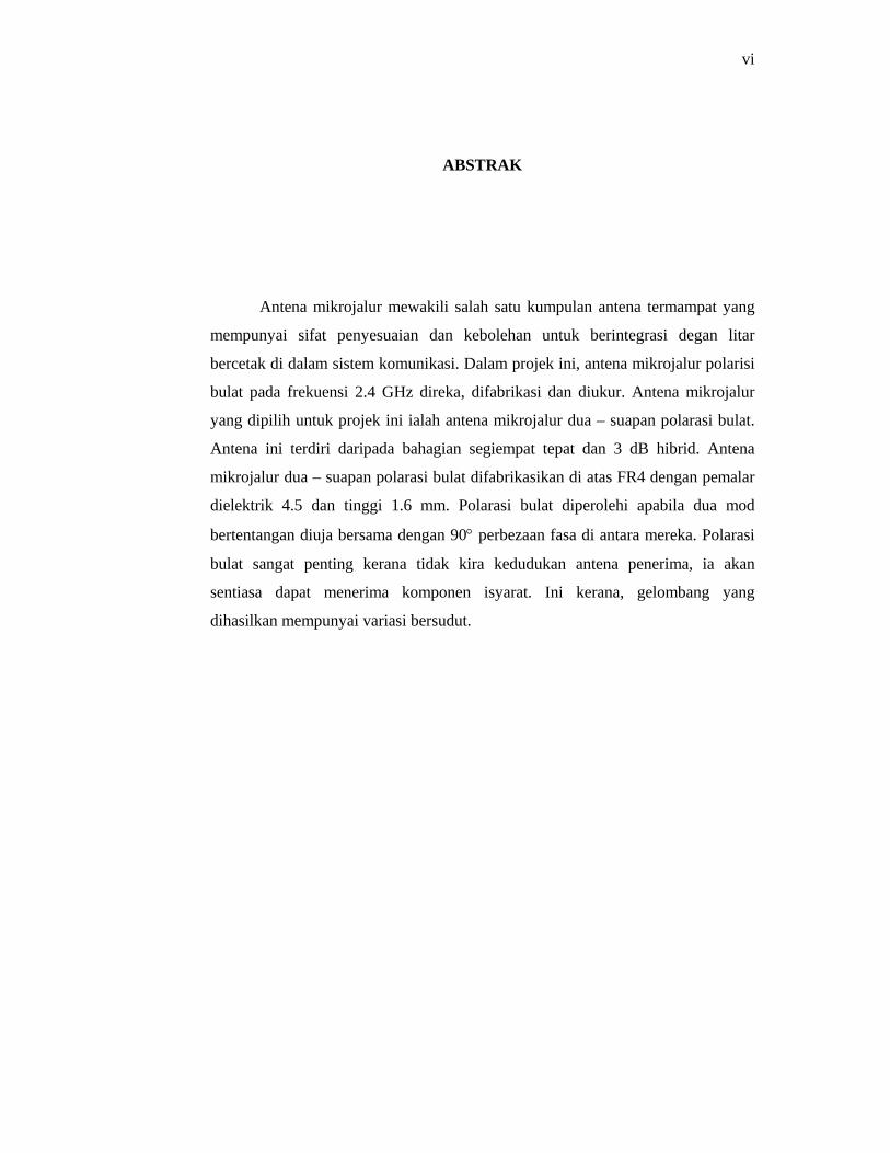
ABSTRAK
Antena mikrojalur mewakili salah satu kumpulan antena termampat yang
mempunyai sifat penyesuaian dan kebolehan untuk berintegrasi degan litar
bercetak di dalam sistem komunikasi. Dalam projek ini, antena mikrojalur polarisi
bulat pada frekuensi 2.4 GHz direka, difabrikasi dan diukur. Antena mikrojalur
yang dipilih untuk projek ini ialah antena mikrojalur dua – suapan polarasi bulat.
Antena ini terdiri daripada bahagian segiempat tepat dan 3 dB hibrid. Antena
mikrojalur dua – suapan polarasi bulat difabrikasikan di atas FR4 dengan pemalar
dielektrik 4.5 dan tinggi 1.6 mm. Polarasi bulat diperolehi apabila dua mod
bertentangan diuja bersama dengan 90° perbezaan fasa di antara mereka. Polarasi
bulat sangat penting kerana tidak kira kedudukan antena penerima, ia akan
sentiasa dapat menerima komponen isyarat. Ini kerana, gelombang yang
dihasilkan mempunyai variasi bersudut.

vii
TABLE OF CONTENTS
CHAPTER TITLE PAGE
TITLE i
CERTIFICATION ii
DEDICATION iii
ACKNOWLEDGEMENT iv
ABSTRACT v
ABSTRAK vi
TABLE OF CONTENTS vii
LIST OF TABLES xi
LIST OF FIGURES xii
LIST OF SYMBOLS xiii
1 INTRODUCTION 1
1.1 Introduction 1
1.2 Wireless Local Area Network (WLAN) System 2
1.3 Objective 3
1.4 Scope of work 3
1.5 Outline of thesis 4
1.6 Summary 5
2 MICROSTRIP ANTENNA 6
2.1 Introduction 6
2.2 Antenna properties 10
2.2.1 Radiation pattern 10

viii
TABLE OF CONTENTS
CHAPTER TITLE PAGE
2.2.2 Return loss 12
2.2.3 Gain 12
2.2.4 Half power beamwidth 13
2.2.5 VSWR 14
2.2.6 Efficiency 14
2.2.7 Bandwidth 14
2.3 Feeding methods 15
2.3.1 Microstrip line feed 16
2.2.2 Coaxial feed 16
2.3.3 Aperture coupled feed 17
2.3.4 Proximity coupled feed 18
2.4 Summary 20
3 MICROSTRIP ANTENNA POLARIZATION 21
3.1 Polarization type 21
3.1.1 Linear polarization 22
3.1.2 Circular polarization 25
3.1.3 Elliptical polarization 28
3.2 Circularly polarized microstrip antenna 29
3.2.1 Dual– fed circular polarization (CP) patch
antenna
31
3.2.2 Singly fed circular patches 32
3.3 Summary 33
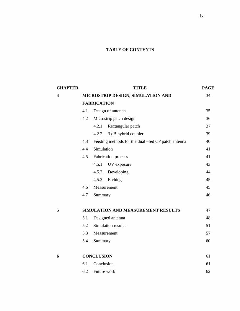
ix
TABLE OF CONTENTS
CHAPTER TITLE PAGE
4 MICROSTRIP DESIGN, SIMULATION AND
FABRICATION
34
4.1 Design of antenna 35
4.2 Microstrip patch design 36
4.2.1 Rectangular patch 37
4.2.2 3 dB hybrid coupler 39
4.3 Feeding methods for the dual –fed CP patch antenna 40
4.4 Simulation 41
4.5 Fabrication process 41
4.5.1 UV exposure 43
4.5.2 Developing 44
4.5.3 Etching 45
4.6 Measurement 45
4.7 Summary 46
5 SIMULATION AND MEASUREMENT RESULTS 47
5.1 Designed antenna 48
5.2 Simulation results 51
5.3 Measurement 57
5.4 Summary 60
6 CONCLUSION 61
6.1 Conclusion 61
6.2 Future work 62

x
TABLE OF CONTENTS
CHAPTER TITLE PAGE
REFERENCES 63
APPENDICE
APPENDIX A Calculation of axial ratio

xi
LIST OF TABLES
TABLE NO. TITLE PAGE
2.1 Advantages and disadvantages of microstrip antenna 9
2.2 Comparing the different feed techniques 19
4.1 Performance of microstrip antenna 36
5.1 Length and width for the calculated microstrip patch
antenna
48

xii
LIST OF FIGURES
FIGURE NO. TITLE PAGE
2.1 Microstrip antenna 7
2.2 Common shapes of microstrip patch elements 7
2.3 Operations of a Microstrip Patch 8
2.4 3D representation of a radiation pattern 11
2.5 Microstrip Line Feed 16
2.6 Coaxial probe feed 17
2.7 Aperture coupled Feed 18
2.8 Proximity – coupled Feed 19
3.1 Linear polarized EM wave 22
3.2 Vertical linear polarization 22
3.3 Horizontal linear polarization 23
3.4 Linear polarization 23
3.5 Circularly polarize EM wave 25
3.6 Left – hand circular polarization 26
3.7 Right – hand circular polarization 26
3.8 Various type of circularly polarized microstrip
antenna
30
3.9 Dual – fed CP patches 31
3.10 Singly fed circular patches 32
4.1 Design methodology 35
4.2 Dual – fed CP patch antenna with 3dB hybrid 37
4.3 Rectangular Patch Antenna 38
4.4 3 dB hybrid coupler 39
4.5 Flow chart for fabrication process 42

xiii
LIST OF FIGURES
FIGURE NO. TITLE PAGE
4.6 UV exposure machine 43
4.7 Developing the antenna 44
4.8 Microwave Test set 45
5.1 Layout of the microstrip patch antenna 47
5.2 Schematic diagram of the antenna 49
5.3 2D view of the microstrip patch antenna 50
5.4 3D view of the microstrip antenna 50
5.5 Return loss of the microstrip patch antenna 51
5.6 VSWR for the antenna 52
5.7 Radiation pattern 53
5.8 Half power beamwidth 54
5.9 Left hand circular polarization 55
5.10 Right hand circular polarization 56
5.11 Axial ratio for the microstrip antenna 57
5.12 Photo of the fabricated microstrip patch antenna 58
5.13 Microwave Test Set 58
5.14 Measurement of the return loss 59
5.15 Comparison between simulation and measurement 59

xiv
LIST OF SYMBOLS
mm - milimeter
dB - decibel
Hz - hertz
K - kilo
d - diameter
h - height
L - length
W - width
Γ - reflection coefficient
Z0 - characteristic impedance
λο - free-space wavelength
rε - dielectric constant of the substrate
t - patch thickness
c - speed of light 3x 10⁻⁸ m/s
CHAPTER 1
INTRODUCTION
1.1 Introduction
Microstrip antenna technology began its rapid development in the late
1970s. By the early 1980s basic microstrip antenna elements and arrays were
fairly well establish in term of design and modeling [1]. In the last decades
printed antennas have been largely studied due to their advantages over other
radiating systems, such as light weight, reduced size, low cost, conformability and
possibility of integration with active devices.
Therefore, this project is aimed to design a circularly polarized antenna at
2.4 GHz. The main advantage of using circular polarization is that regardless of
receiver orientation, it will always receive a component of the signal. This is due
to the resulting wave having an angular variation [2].
This microstrip antenna consists of a radiating patch on the dielectric
substrate. There are various shapes that can be used as the radiating patch.
However, for this project, square patch with 3 dB hybrid will be designed. With
dual feeding methods, two orthogonal modes are equally excited with 90° phase
difference

2
between them, thus the antenna will polarize circularly. The microstrip antenna is
simulated and tested using Microwave Office, where electromagnetic analysis
tools will be used.
The designed is fabricated and tested with network analyzer. Both
simulated and measured results will be compared.
1.2 Wireless Local Area Network (WLAN) System
Wireless LAN can be used either to replace wired LAN, or as an extension
of the wired LAN infrastructure. There are in general two types of antennas for
WLAN applications, fixed WLAN base stations or access points, and the other is
for mobile communication terminals.
For base station applications, impedance matching for WLAN bandwidth
should be better than 1.5:1 VSWR or about 14 dB return loss [3], similar to the
cellular system base station. Antenna that capable to excite circular polarization is
very attractive because it can overcome the multipath fading problem, thus
enhance the system performance, especially indoor WLAN operation [3].
Currently, the most commonly used WLAN system is the IEEE 802.11b
system [4]. A key requirement of WLAN system is that it should be low profile,
where it is almost invisible to the user. For this reason, the microstrip patch
antennas are the antennas of choice for WLAN use due to their small real estate
area and the ability to be designed to blend into the surroundings.

3
1.3 Objective
The objective of this project is to design, simulate, and fabricate a circular
polarization microstrip antenna at 2.4 GHz frequency. The microstrip antenna uses
dual feed techniques. The microstrip antenna is then simulated, fabricated and
measured.
1.4 Scope of work
The project started with designing the microstrip antenna. Then, the
microstrip antenna is simulated using the Microwave Office software. After the
simulation, the microstrip antenna is fabricated using FR4, with dielectric constant
(εr) 4.5 and height of 1.6 mm. Finally the microstrip antenna is measured using the
network analyzer and the measured values are compared with the simulated
values.

4
1.5 Outlines of thesis.
The outlines of the thesis are as follows:
Chapter 1: This chapter provides the introduction to the project, objective and
scope of work.
Chapter 2: This chapter covers the literature review on the microstrip antenna,
the antenna properties, and the feeding methods.
Chapter 3: This chapter covers polarization topic, such as linear and circular
polarization. This chapter also covers the available microstrip
antenna that excites circular polarization.
Chapter 4: Chapter 4 consists of the microstrip design, simulation and
fabrication process of the microstrip antenna.
Chapter 5: This chapter provides the results that are obtained from the
simulation as well as from the measurement.
Chapter 6: This chapter gives the conclusion and future work for this project.

5
1.6 Summary
This chapter provides introduction of the project, followed by a brief
explanation about wireless local area network (WLAN). This chapter also covers
the objective of the project, as well as scope of work that involved. Finally, a
summation of each chapter is briefly outlined.
61
CHAPTER 6
CONCLUSION
6.1 Conclusion
There is various type of microstrip antenna that is able to excite a circular
polarization. For this project, dual – fed circular polarization microstrip antenna is
chosen. The microstrip antenna is design to operate at 2.4 GHz frequency. The
dual –fed circular polarization microstrip antenna is successfully implemented and
fabricated. The microstrip antenna resonates at 2.47 GHz and gives a good return
loss, which is -23.25 dB. This is a good value because only 0.47 % power is
reflected and 99.53 % power is transmitted. The VSWR of the microstrip antenna
is 1.2:1, which shows that the level of mismatched for the microstrip antenna is
not very high. High VSWR means that the port is not properly matched. The
bandwidth of this microstrip antenna is also good, which is 17.04 % and the
maximum radiation occurs at -40° with gain of 4.28 dB. The microstrip antenna is
said to be circular if the axial ratio is 0 dB. From the calculation of axial ratio,
most of the angles give 0 dB value, thus prove that the microstrip antenna polarize
circularly.

62
6.2 Future work
There is various type of antenna that can excite circular polarization. In
dual feed circular polarization, the rectangular patch can be changed to circular
patch. There is also off line feeding method in dual –fed circular polarization
microstrip antenna. Besides dual fed, there is also a singly – fed circular
polarization. Therefore, in future work, different type of circular polarization can
be designed and studied, so that, a comparisons can be made to the antennas, thus
better microstrip antenna that excites circular polarization can be obtained.
The dual – fed circular polarization microstrip antenna can also be
arranged in an array and become the phase array antenna. This phase array
antenna can steer the radiation without physically moving the antenna. This
antenna can be applied to satellite communication. The circular polarization is
particularly desired since the polarization of linear polarized radio wave may be
rotated the signal passes any anomalies (such as Faraday rotation) in the
ionosphere. Furthermore, due to the position of the Earth with respect to the
satellite, geometric differences may vary especially if the satellite appears to move
with respect to the fixed Earth bound station. Circular polarization will keep the
signal constant regardless of these anomalies.

63
REFERENCES
1. Pozar, D. M.(1996). A Review of Aperture Coupled Microstrip Antennas:
History, Operation, Development, and Applications, University of
Massachusetts: Article review.
2. Saed, R. A., and Khatun, S. (2005). Design of Microstrip Antenna for
WLAN, Journal of Applied Sciences. 5 (1): 47 – 51
3. Lu Wong, K (2003). Planar Antennas for Wireless Communications.
Hoboken, N. J: John Wiley & Sons.
4. Haider, S. (2003). Microstrip patch antennas for broadband indoor
wireless system. University of Auckland: Maters Thesis.
5. Balanis, C. A. (1997). Antenna Theory, Analysis and design. 2nd ed.
Hoboken, N. J: John Wiley & Sons.
6. Clarke, R. W. Lecture notes and lab scripts. University of Bradford
7. Mohd. Kamal bin A. Rahim. Teaching Module, RF / Microwave and
Antenna Design. UTM
8. Nakar, P. S. (2004). Design of a compact microstrip patch antenna for use
in wireless / cellular devices. Florida State University: Masters Thesis

64
9. Haneishi, M., and Suzuki, Y. (2000). Circular polarization and bandwidth.
In: Garg, R., Bharti, P., Bahl, I., and Ittipiboon, A. Microstrip Antenna
Handbook. Artech House, Boston. 219
10. Raisert, J. H. Antenna polarization application note.
11. Ramirez, R. R. (2000). Single – Feed Circularly Polarized Microstrip Ring
Antenna and Arrays. IEEE Transactions on Antennas and propagation. 48
(7): 1040 – 1047
12. Li, Q., and Shen, Z. (2002). An Inverted Microstrip – Fed Cavity – backed
Slot Antenna for Circular Polarization. IEEE Antennas for Wireless
propagation letters. 1: 190 – 192
13. Lu Wong, K (2003). Compact and Broadband Microstrip Antennas.
Hoboken, N. J: John Wiley & Sons.
14. Dafalla, Z. I., Kuan, W. T. Y., Abdel Rahman, A. M., and Shudakar, S. C.
(2004). Design of a Rectangular Microstrip Patch Antenna at 1 GHz. 2004
RF and Microwave Conference. October 5 – 6: 145 – 149
15. Setian, L. (1998). Practical Communication Antennas with Wireless
Applications.Upper Saddle River, NJ: Prentice Hall