Design Loads on Railway Substructure: Sensitivity Analysis ...giannakoskonstantinos.com/Engineering...
11
IJR International Journal of Railway Vol. 7, No. 2 / June 2014, pp. 46-56 Vol. 7, No. 2 / June 2014 − 46 − The Korean Society for Railway Design Loads on Railway Substructure: Sensitivity Analysis of the Influence of the Fastening Stiffness Konstantinos GIANNAKOS † Abstract The superstructure of the railway track undertakes the forces that develop during train passage and distributes them towards its seating. The track panel plays a key role in terms of load distribution, while at the same time it maintains the geometrical distance between the rails. The substructure and ballast undergo residual deformations under high stresses that contribute to the deterioration of the so-called geometry of the track. The track stiffness is the primary contributing factor to the amount of the stresses that develop on the substructure and is directly influenced by the fastening resil- ience. Four methods from the international literature are used in this paper to calculate the loads and stresses on the track substructure and the results are compared and discussed. A parametric investigation of the stresses that develop on the substructure of different types of railway tracks (i.e. balastless vs ballasted) is performed and the results are presented as a function of the total static track stiffness. Keywords: Ballasted Track, Ballastless Track, Static and Dynamic Stiffness Coefficients, Actions, Mean Pressure 1. Introduction The railway track superstructure is the equivalent of the road pavement and as in the case of pavements there are flexible and rigid track superstructures. The main differ- ence between the two types of infrastructure is that the loads in railways are applied in two discrete locations along the rails, whereas in road pavements the location of the load application is random. The track superstructure is a multilayered system that consists of the rails, which sup- port and guide the train wheels and distribute the wheel loads, the ties with their fastenings which distribute the loads applied by the rails and maintain the rail gauge. In the case of the classic ballasted track the superstructure also includes the ballast (Fig. 1), the equivalent of a flexi- ble pavement, and the blanket layer (sub-ballast) consist- ing of compacted sand and gravel, which further distributes the loads and protects the substructure from the penetration of crashed ballast particles, mud ascent and pumping. In the case of the more recently developed Bal- lastless or Slab Track (Fig. 2) the superstructure also includes the concrete slab or Continuously Reinforced Concrete Pavement (CRCP) which is the equivalent of a rigid pavement. The concrete slab seats on a series of suc- cessive bearing layers with a gradually decreasing modu- lus of elasticity: the Cement Treated Base (CTB), underlain by the Frost Protection Layer (FPL) and the foundation or prepared subgrade. The three layers under the concrete slab (i.e. CTB, FPL and foundation) consti- tute the substructure of the Slab Track. The Slab Track is typically used in High Speed lines (V>200 km/h) of mixed passenger and freight traffic with maximum axle load of 22.5 t. Another type of Ballastless Track is the Embedded Track, which is similar to the Slab Track and is typically used in terminal port stations and maintenance facilities of railway vehicles to minimize the maintenance needs of the track. In these applications there is a need to replace the ballast-bed with a concrete floor for functional reasons (i.e. washing of vehicles and flowing out of the waste water and oils, maintenance pits between the two rails, cir- Corresponding author: F. ASCE, M. TRB-AR050 & AR060 Comm., AREMA, fib., Visiting Professor of Design and Operation of Railway Systems, Dpt. Civil Engineering, University of Thessaly, Greece. E-mail : [email protected], [email protected]. ⓒThe Korean Society for Railway 2014 http://dx.doi.org/10.7782/IJR.2014.7.2.46
Transcript of Design Loads on Railway Substructure: Sensitivity Analysis ...giannakoskonstantinos.com/Engineering...

IJR International Journal of Railway
Vol. 7, No. 2 / June 2014, pp. 46-56
Vol. 7, No. 2 / June 2014 − 46 −
The Korean Society for Railway
Design Loads on Railway Substructure:
Sensitivity Analysis of the Influence of the Fastening Stiffness
Konstantinos GIANNAKOS†
Abstract
The superstructure of the railway track undertakes the forces that develop during train passage and distributes them
towards its seating. The track panel plays a key role in terms of load distribution, while at the same time it maintains the
geometrical distance between the rails. The substructure and ballast undergo residual deformations under high stresses
that contribute to the deterioration of the so-called geometry of the track. The track stiffness is the primary contributing
factor to the amount of the stresses that develop on the substructure and is directly influenced by the fastening resil-
ience. Four methods from the international literature are used in this paper to calculate the loads and stresses on the track
substructure and the results are compared and discussed. A parametric investigation of the stresses that develop on the
substructure of different types of railway tracks (i.e. balastless vs ballasted) is performed and the results are presented as
a function of the total static track stiffness.
Keywords: Ballasted Track, Ballastless Track, Static and Dynamic Stiffness Coefficients, Actions, Mean Pressure
1. Introduction
The railway track superstructure is the equivalent of the
road pavement and as in the case of pavements there are
flexible and rigid track superstructures. The main differ-
ence between the two types of infrastructure is that the
loads in railways are applied in two discrete locations
along the rails, whereas in road pavements the location of
the load application is random. The track superstructure is
a multilayered system that consists of the rails, which sup-
port and guide the train wheels and distribute the wheel
loads, the ties with their fastenings which distribute the
loads applied by the rails and maintain the rail gauge. In
the case of the classic ballasted track the superstructure
also includes the ballast (Fig. 1), the equivalent of a flexi-
ble pavement, and the blanket layer (sub-ballast) consist-
ing of compacted sand and gravel, which further
distributes the loads and protects the substructure from the
penetration of crashed ballast particles, mud ascent and
pumping. In the case of the more recently developed Bal-
lastless or Slab Track (Fig. 2) the superstructure also
includes the concrete slab or Continuously Reinforced
Concrete Pavement (CRCP) which is the equivalent of a
rigid pavement. The concrete slab seats on a series of suc-
cessive bearing layers with a gradually decreasing modu-
lus of elasticity: the Cement Treated Base (CTB),
underlain by the Frost Protection Layer (FPL) and the
foundation or prepared subgrade. The three layers under
the concrete slab (i.e. CTB, FPL and foundation) consti-
tute the substructure of the Slab Track. The Slab Track is
typically used in High Speed lines (V>200 km/h) of mixed
passenger and freight traffic with maximum axle load of
22.5 t.
Another type of Ballastless Track is the Embedded
Track, which is similar to the Slab Track and is typically
used in terminal port stations and maintenance facilities of
railway vehicles to minimize the maintenance needs of the
track. In these applications there is a need to replace the
ballast-bed with a concrete floor for functional reasons
(i.e. washing of vehicles and flowing out of the waste
water and oils, maintenance pits between the two rails, cir-
† Corresponding author: F. ASCE, M. TRB-AR050 & AR060 Comm., AREMA,
fib., Visiting Professor of Design and Operation of Railway Systems, Dpt. Civil
Engineering, University of Thessaly, Greece.
E-mail : [email protected], [email protected].
ⓒThe Korean Society for Railway 2014
http://dx.doi.org/10.7782/IJR.2014.7.2.46
− 47 −
Konstantinos GIANNAKOS / IJR, 7(2), 46-56, 2014
culation of road vehicles on the tracks, transshipment of
cargo etc.). Its main difference from the Slab Track is the
low speed of train circulation and, consequently, the small
magnitude of dynamic loads. In both cases of Ballastless
Track systems presented above the role of ballast-bed and
blanket layer is undertaken by a concrete slab.
The application of Slab Track and Embedded Track
technology in a railway network creates the need for Tran-
sition Zones, which serve as interfaces between the bal-
lastless and ballasted track sections, where significant and
abrupt change in stiffness occurs. The Transition Zones
guarantee a smooth stiffness transition between slab track
and ballast-bed, resulting in a smooth variation of the
forces that act on the track (see Giannakos et al., 2010c).
In order to adopt the Slab Track technology, the Greek
Railways performed an extensive investigation program
that studied Slab Track systems laid in High-Speed tracks
(Vmax > 200 km/h) under operation, mainly in Germany.
Two types of Slab Track systems were considered: Rheda
Classic, which was the first application of Slab Track that
took place in 1972, and Rheda 2000, which is the most up-
to-date, modern and most technologically advanced type
of the Rheda Slab Track “family”. Based on the findings
of the research program these two types of Slab Track
were selected for the Greek railway network and applied
in the High-Speed Line between Patras - Athens/Piraeus –
Thessaloniki, co-funded by the European Union and the
Greek Government.
The stress on the substructure plays a key role in the
design and maintenance of High Speed railway tracks and
its magnitude mainly depends on the track stiffness coeffi-
cient (Giannakos, 2011). However, there is a lack of data
in the international literature correlating the magnitude of
stress on the track substructure and the track stiffness coef-
fient of High Speed lines under operation. The research
performed for the Greek Railway network (Giannakos,
2008, Tsoukantas, 1999) addressed this issue. Its findings,
highlighting the interaction between superstructure and
substructure of a railway track, are presented in this paper.
A method for the calculation of loads and stresses on a
railway track was developed as a result of this research
(Giannakos, 2004). This method together with three meth-
ods found in the international literature are used to calcu-
late the stresses on the track substructure and the results
are compared and discussed. The results are presented as a
function of the total static track stiffness, for the two sys-
tems applied in High-speed lines under operation in the
Greek network: (i) Rheda type Slab Track (Fig. 2a), and
(ii) ballasted track with 2.60 m monoblock prestressed
concrete ties and W14 fastening(Fig. 1).
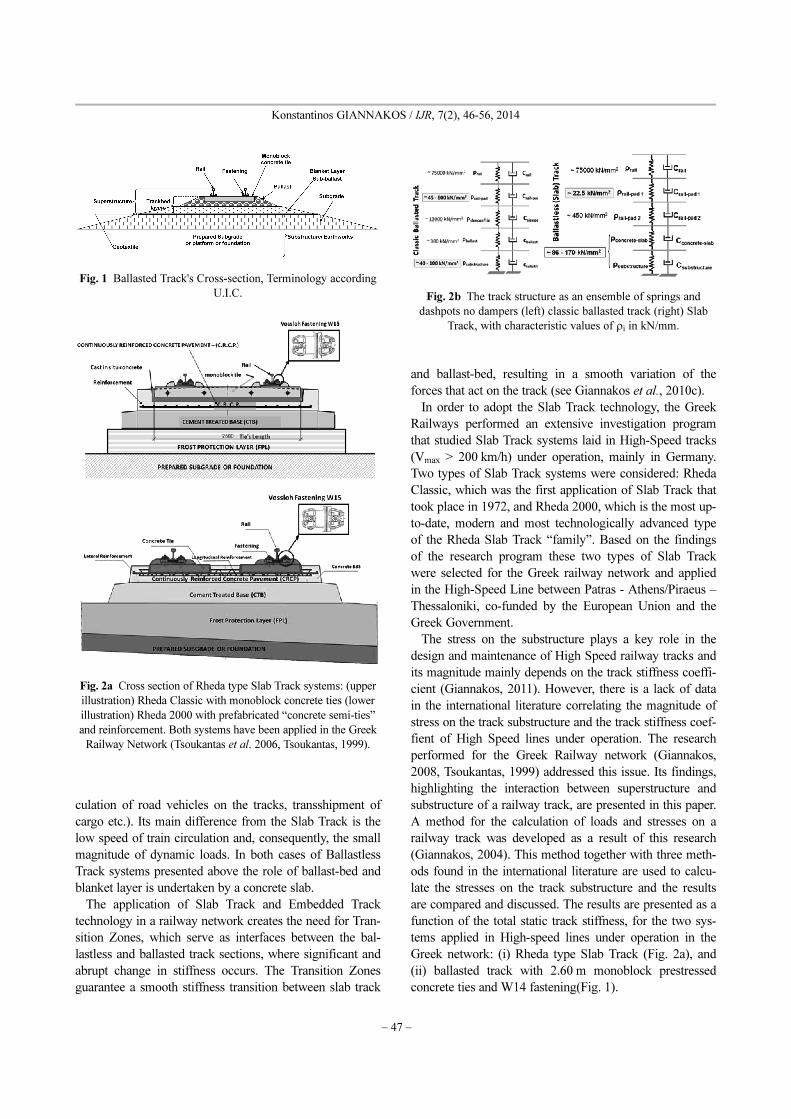
Fig. 1 Ballasted Track's Cross-section, Terminology according
U.I.C.
Fig. 2a Cross section of Rheda type Slab Track systems: (upper
illustration) Rheda Classic with monoblock concrete ties (lower
illustration) Rheda 2000 with prefabricated “concrete semi-ties”
and reinforcement. Both systems have been applied in the Greek
Railway Network (Tsoukantas et al. 2006, Tsoukantas, 1999).
Fig. 2b The track structure as an ensemble of springs and
dashpots no dampers (left) classic ballasted track (right) Slab
Track, with characteristic values of ρi in kN/mm.

Design Loads on Railway Substructure: Sensitivity Analysis of the Influence of the Fastening Stiffness
− 48 −
2. Methods for the Calculation of Loads on a Railway Track
2.1 General
The four methods used for the calculation of the stresses
on track are:
• The method presented in the French literature (Alias,
1984, Prud’homme et al., 1976, RGCF, 1973),
• The method presented in the German Literature (Fas-
tenrath, 1981, Eisenmann, 2004),
• The method presented in the American literature
(AREMA, 2005, Hay, 1982)
• The method proposed by Giannakos (2004, Gianna-
kos et al., 2009d) combining an analytical framework,
experimental results and field observations form the Greek
Railway Network.
All methods model the railway track as a continuous
beam on elastic foundation and use different assumptions
in their approximation of the random nature of load
application on a railway track. In all methods the total
static stiffness coefficient of the railway track, total, plays
a key role in the load distribution. This coefficient, is
given by:
(1)
where i is each individual layer of the multilayered struc-
ture that constitutes the track as depicted in Fig. 2b).
Due to the random nature of the moving loads, a proba-
bilistic approach is more appropriate for the calculation of
the loads acting on each point along the track, the result-
ing actions on each tie, and stresses and strains on the dif-
ferent layers of the track. According to this approach, the
increase of the mean value of the vertical wheel load is
estimated for the statistically desirable safety level. In the
aforementioned methods this is considered either through
a dynamic load coefficient, which essentially increases the
value of the static load, or through a probabilistic frame-
work, where the mean load is increased by an appropriate
number of standard deviations to cover a certain probabil-
ity of occurrence.
2.2 Method cited in the french literature
The action on the tie is calculated through the following
equation (2):
(2)
where: Rtotal = the total action on the tie after the distribu-
tion of the acting load, Qwheel = the static load of the wheel
(half the axle load), Qα = load due to cant deficiency (or
superelevation), σ(ΔQNSM) = standard deviation of the
Non-Suspended (or unsprung) Masses of vehicle, σ(ΔQSM)
= standard deviation of the Suspended (or sprung) Masses
of the vehicle. The factor of 2 in the equation above cov-
ers a 95.5 % probability of occurrence.
Moreover, stat is the static reaction coefficient of the tie
which is equal to:
(3)
ρtotal = coefficient of total static stiffness of track in kN/
mm, = distance among the ties in mm, J = modulus of
elasticity and moment of inertia of the rail.
2.3 Method cited in the german literature
The action on the tie is estimated from the following:
(4a)
where L the elastic length of the track given by:
(5)
and stat is calculated through equation (3).
Furthermore:
(6)
where ranges between 0.1ϕ and 0.3ϕ depending on the
condition of the track according to the following:
= 0.1·ϕ for excellent track condition, = 0.2·ϕ for
good track condition, = 0.3·ϕ for poor track condition
and ϕ is a function of the speed as shown below: in the
whole paragr.
For V < 60 km/h: ϕ = 1.
For 60 < V < 200 km/h:
(7)
where V the maximum speed on a section of track and t a
coefficient that depends on the probability of occurrence
(t=1 for P=68.3%, t=2 for P=95.5% and t=3 for P=99.7%).
Finally equation (4a) is transformed to:
(4b)
for Vmax ≤ 200 km/h, with probability of occurrence P=
99.7%, where, Qwheel = the static load of the wheel (half
1
ρtotal------------ 1
ρi----
i 1=
v
∑=
Rtotal Qwheel Qα
2 σ2ΔQNSM( )[ ] σ
2ΔQSM( )[ ]+⋅+ +( )=
Astat 1.35⋅ ⋅
A
Astat1
2 2---------- 4
ρtotal 3⋅
E J⋅-------------------⋅=
Rmax SQtotal ⋅
2 L⋅------------------- Rmax⇒
Qtotal
2------------- 4
ρtotal 4⋅
4 E J ⋅ ⋅ ⋅---------------------⇒⋅= = =
Rmax⇒ Qtotal
1
2 2----------
ρtotal 3⋅
E J⋅--------------------4⋅⋅ Astat Qtotal⋅= =
L4 E J ⋅ ⋅ ⋅ρtotal
---------------------4=
A
Qtotal Qwheel 1 t s⋅+( )⋅=
s
s s
s
ϕ 1V 60–
140--------------+=
Rmax 1 0.9 1Vmax 60–
140----------------------+⎝ ⎠
⎛ ⎞⋅+⎝ ⎠⎛ ⎞ Astat Qwheel⋅ ⋅=

− 49 −
Konstantinos GIANNAKOS / IJR, 7(2), 46-56, 2014
the axle load), stat is calculated through equation (3).
Prof. Eisenmann for speeds above 200 km/h proposed a
reduced factor of dynamic component:
(4c)
Equation (4c) leads to even greater under-estimation of
the acting loads on track -than equation (4b)- with possi-
ble consequences to the dimensioning of track elements -
like e.g. sleepers- as the literature describe ([1], [2], [15]),
thus equation (4b) should be preferred for the sleepers’
dimensioning.
2.4 Method cited in the american literature
This method is described in AREMA (2005, p. 16-10-26
to 16-10-32 and Chapter 30) and in Hay (1982, p. 247-
273). The total load (static and dynamic) acting on the
track depends on an impact factor (AREMA, 2003, p. 16-
10-9, Hay, 1982, p. 256):
(8)
where D33 is the diameter of a 33-inch reference wheel,
Dwheel the wheel diameter of the vehicle examined in
inches, and V the speed in miles/hour
The total load is:
(9)
U in psi is the rail support modulus derived by the rela-
tion p=Uy, U=ρ/ , and
(10)
The influence curve for the deflection, y, is used to
determine the maximum value of pressure max and the
maximum rail seat load Rmax on an individual tie, which is
given by the following equation:
(11a)
where Qtotal is calculated from equation (9) and stat from
equation (3). Note that this method does not account for
the probability of occurrence.
Finally equation (11a) is transformed to:
(11b)
2.5 Giannakos (2004) method
The actions on the track panel are calculated through the
following equation (12a):
(12a)
where Qwh = the static wheel load, Qα = the load due to
cant deficiency, dyn = dynamic coefficient of the tie reac-
tion, μ = coefficient of dynamic load (3 for a probability
99.7 % and 5 for 99.9 %), σ(ΔQNSM) = the standard devia-
tion of the dynamic load due to non suspended masses,
(QSM) = the standard deviation of the dynamic load due to
suspended masses and :
(13)
where hTR the total dynamic stiffness of the track:
(14)
Giannakos (2004, 2010a) and Giannakos et al. (2009d)
describe in detail the determination of parameters dynam
and hTR. The main differences of this method compared to
the methods presented above are: (i) the use of the
dynamic coefficient dynam (instead of stat) for the distri-
bution of the static and semi-static components of the load,
and (ii) the dynamic component of the load is not distrib-
uted to the adjacent ties (see Giannakos et al., 2009d).
Finally equation (12a) is transformed to equation (12b)
[Giannakos, 2014]:
(12b)
2.6 Comparison of theoretical calculations
of the loads with observations on track
In Greece between 1972 and 1999, twin-block concrete
ties of French technology were exclusively used, namely
Vagneux U2, U3 with RN fastenings, for tracks designed
for Vmax = 200 km/h and temporary operational speed
Voper = 120-140 km/h. Extended cracking was observed at
a percentage of more than 60 % of the U2/U3 ties laid on
track. The methods cited in the international literature at
that time (French, German, American) did not provide any
satisfactory justification for the appearance of the cracks,
resulting in much lower values of actions on ties than the
cracking threshold, thus predicting no cracking at all. After
A
Rmax 1 0.9 1V 60–
380--------------+⎝ ⎠
⎛ ⎞⋅+⎝ ⎠⎛ ⎞ Astat Qwheel⋅ ⋅=
θD33 V⋅
Dwheel 100⋅---------------------------=
Qtotal Qwheel 1 θ+( )⋅=
βU
4 E J⋅ ⋅---------------4
ρ
4 E J ⋅ ⋅ ⋅---------------------4
1
L---= = =
p
Rmax pmax ⋅ U ymax ⋅ ⋅ U ymax ⋅ ⋅ = = =
U=β Qtotal⋅
2 U⋅------------------- ⋅ ⋅
ρtotal
4 EJ -------------4
Qtotal ⋅
2-------------------⋅=
Rmax⇒1
2 2----------
ρtotal 3⋅
E J⋅--------------------4 Qtotal⋅ ⋅ Astat Qtotal⋅= =
A
Rmax Astat 1D33 V⋅
Dwheel 100⋅---------------------------+⎝ ⎠
⎛ ⎞ Qwheel⋅ ⋅=
R'max Qwh Qα
+( ) Adyn μ σ ΔQNSM( )2 σ ΔQSM( )2+⋅+⋅=
A
Adynam1
2 2----------
3
hTR⋅
E J⋅-----------------4⋅=
hTR1
2 2---------- E J
ρtotal
------------⋅ ⋅4⋅=
A
A A
Rmax
1
2 28----------
ρtotal 3
⋅
E J⋅--------------------⎝ ⎠⎜ ⎟⎛ ⎞
16 Qwheel Qα
+( )⋅ ⋅=

Design Loads on Railway Substructure: Sensitivity Analysis of the Influence of the Fastening Stiffness
− 50 −
an extensive research that included collaboration among
various universities and railway organizations in Europe,
the Giannakos (2004) method was developed whose
results successfully predicted the extended cracking of the
U2/U3 ties (Giannakos, 2004, 2010c, 2011; Giannakos &
Loizos, 2009d), calculating actions over the cracking
threshold and in some cases over the failure threshold.
This method was derived from theoretical analyses, mea-
surements from laboratory tests performed in Greece, Aus-
tria, France, Belgium and other European countries and
observations from real on-track experience. The results of
the four methods for a sensitivity analysis of the influence
of the subgrade’s and the pad’s static stiffness coefficient
on the acting loads are depicted in Fig. 3. The method was
calibrated to for the calculation of loads on ballastless
track systems and the results were verified against mea-
surements on Slab Track (Giannakos, 2010a). The results
of the method were also presented for lines with Heavy
Haul traffic that are typical in the United States (Gianna-
kos, 2011). Moreover, the International Federation of Con-
crete (fib) has adopted this method for precast concrete
railway track systems (fib, 2006).
3. Calculation of Track’s Total Static Stiffness Coefficient - Verification
against Measurements
As shown in the above equations, the load that is applied
on the track is dependent on the total track stiffness ρtotal.
A range of ballasted track total stiffness values ρtotal, is
used for different combinations of railway track layers/ele-
ments, and their corresponding parameters derived from
measurement data of the German Railways (Alias, 1984,
Giannakos, 2004). The following static stiffness coeffi-
cients per layer/element have been measured on track:
ρrail ranging from 50,000 to 100,000 kN/mm with an
average of 75,000 kN/mm
ρsleeper ranging from 500 to 800 kN/mm for oak wooden
tie and 12,000 to 15,000 kN/mm with an average of
13,500 kN/mm for a concrete tie
ρballast in the order of 380 kN/mm for “polluted” ballast
2 years after laying
ρsubstructure ranging from: (i) 20 to 60 kN/mm for pebbly
subgrade with an average of 40 kN/mm, (ii) 80 to 100 kN/
mm in the case of frozen ballast and ground, and (iii) on
the order of 250 kN/mm for the case of a ballast-bed of
small thickness laid on the concrete base of a tunnel or a
bridge deck .
The tie-pad stiffness, pad, plays a key role in the loa-
ding of the tie, and its value is typically estimated from the
load-deflection curve that is provided by the manufacturer
using a trial-and-error method (Giannakos, 2004).
For the Slab Track, Table 1 can be used to determine the
total track stiffness, ρtotal. On the same table total stiffness
values are also provided for the ballasted track for
different ballast conditions. The values were derived from
measurements in the German railway network (Leykauf et
al., 1990). For the ballastless case the classic Rheda type
slab track was used (Fig. 2a – upper illustration).
The data on Table 1 verify the linear relation between
track stiffness, ρtotal, and ballast coefficient, C, which is
ρtotal=CF/2 (Giannakos, 2004), where F is the active seat-
ing surface of the tie (for a B70 tie F=5700 cm2). Based on
the ballast coefficient values listed on Table 1, the follow-
ing stiffness values (Giannakos et al., 2009a) are calcu-
lated (equations 15 a, b, c, d, e, f):
(15a)
ρtotal CF
2---⋅ 0.05
1
1000------------kN
mm3
-------------------5700 100mm
2⋅2
-----------------------------------⋅ 14.25 14kN mm⁄≈= = =
Fig. 3 Calculation of actions on U2/U3 twin-block ties with
the four methods
Table 1 Relation between ballast coefficient C and stiffness
coefficient ρ in a track equipped with UIC60 rails, prestressed
monoblock concrete sleepers B70, and concrete plate/ slab
Bearing Capacity of Substructure
Ballasted Track Ballastless Track
poor good very good poor good very good
C [N/mm3] 0.05 0.10 0.15 0.30 0.35 0.40
ρ [kN/mm] 14 29 43 86 100 114
− 51 −
Konstantinos GIANNAKOS / IJR, 7(2), 46-56, 2014
(15b)
(15c)
(15d)
(15e)
(15f)
The sleepers in the classic Rheda type system are quite
similar to the B70 prestresed concrete ties with active seat-
ing surface of F=5700 cm2 as well. In the case of the Slab
Track, the total track stiffness can be calculated through
Equation (1). It is noted here that the value of slab stiff-
ness (CRCP and the underlying layers) is similar to the
stiffness of a substructure consisting of ballast and frozen
soil as cited in Giannakos (2004, 2009b).
The methodology described above models both the con-
crete bearing slab (CRCP) and the underlying layers (CTP,
FPL, foundation). According to Eisenmann (1994), in situ
measurements of the ballast coefficient in the Newly-Con-
structed Lines in Germany (NBS-Neubaustrecke) indicate
values in the order of 0.60 N/mm3, which would corre-
spond to a total track stiffness of 171 kN/mm. Eisenmann
(1979) also mentions that the mean value of concrete slab
subsidence yslab is 0.23 mm (fluctuating between 0.17 and
0.31 mm). In the Slab Track case (with embedded con-
crete sleepers) Equation (1) is analytically written in the
following form:
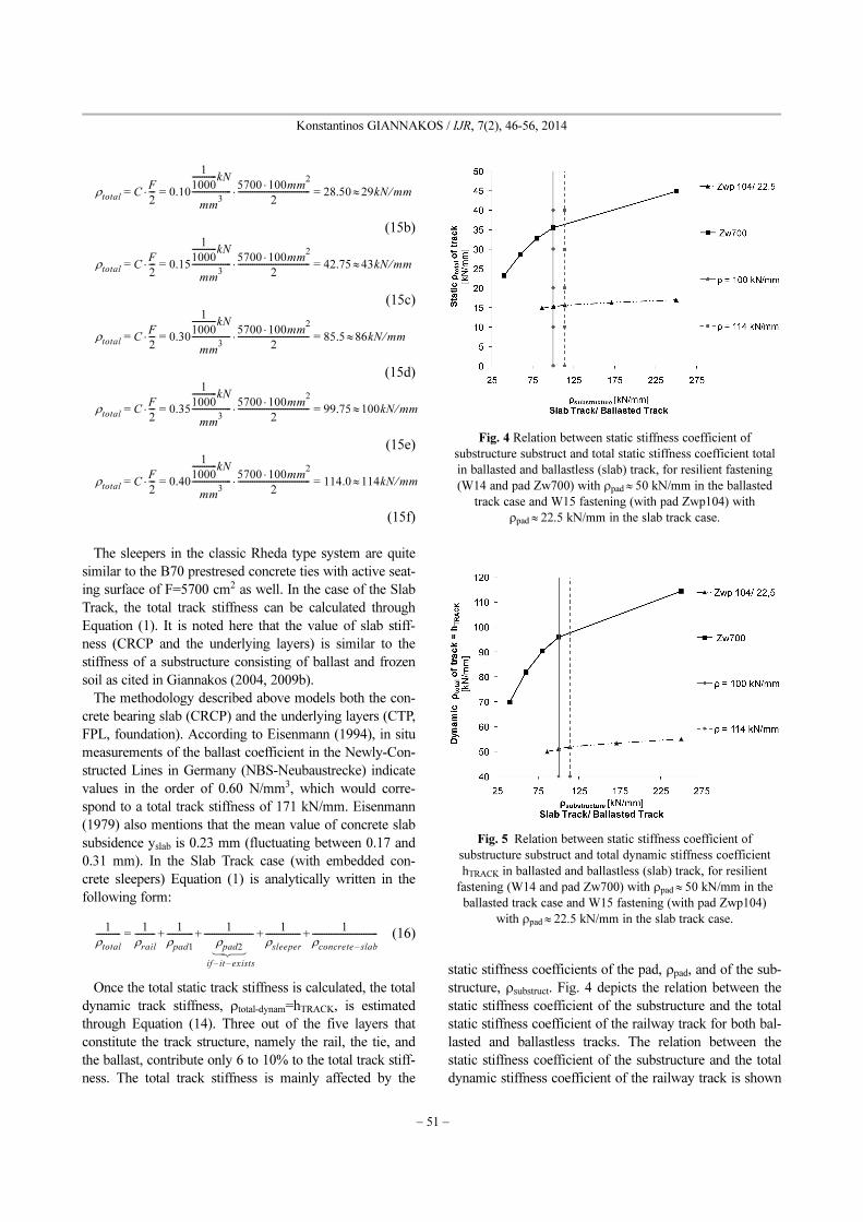
(16)
Once the total static track stiffness is calculated, the total
dynamic track stiffness, ρtotal-dynam=hTRACK, is estimated
through Equation (14). Three out of the five layers that
constitute the track structure, namely the rail, the tie, and
the ballast, contribute only 6 to 10% to the total track stiff-
ness. The total track stiffness is mainly affected by the
static stiffness coefficients of the pad, ρpad, and of the sub-
structure, ρsubstruct. Fig. 4 depicts the relation between the
static stiffness coefficient of the substructure and the total
static stiffness coefficient of the railway track for both bal-
lasted and ballastless tracks. The relation between the
static stiffness coefficient of the substructure and the total
dynamic stiffness coefficient of the railway track is shown
ρtotal CF
2---⋅ 0.10
1
1000------------kN
mm3
-------------------5700 100mm
2⋅
2-----------------------------------⋅ 28.50 29kN mm⁄≈= = =
ρtotal CF
2---⋅ 0.15
1
1000------------kN
mm3
-------------------5700 100mm
2⋅2
-----------------------------------⋅ 42.75 43kN mm⁄≈= = =
ρtotal CF
2---⋅ 0.30
1
1000------------kN
mm3
-------------------5700 100mm
2⋅2
-----------------------------------⋅ 85.5 86kN mm⁄≈= = =
ρtotal CF
2---⋅ 0.35
1
1000------------kN
mm3
-------------------5700 100mm
2⋅
2-----------------------------------⋅ 99.75 100kN mm⁄≈= = =
ρtotal CF
2---⋅ 0.40
1
1000------------kN
mm3
-------------------5700 100mm
2⋅2
-----------------------------------⋅ 114.0 114kN mm⁄≈= = =
1
ρtotal------------
1
ρrail----------
1
ρpad1-------------
1
ρpad2 if it– exists–
------------------------1
ρsleeper-----------------
1
ρconcrete slab–
--------------------------------+ + + +=
⎧ ⎨ ⎩
Fig. 4 Relation between static stiffness coefficient of
substructure substruct and total static stiffness coefficient total
in ballasted and ballastless (slab) track, for resilient fastening
(W14 and pad Zw700) with ρpad 50 kN/mm in the ballasted
track case and W15 fastening (with pad Zwp104) with
ρpad 22.5 kN/mm in the slab track case.
≈
≈
Fig. 5 Relation between static stiffness coefficient of
substructure substruct and total dynamic stiffness coefficient
hTRACK in ballasted and ballastless (slab) track, for resilient
fastening (W14 and pad Zw700) with ρpad 50 kN/mm in the
ballasted track case and W15 fastening (with pad Zwp104)
with ρpad 22.5 kN/mm in the slab track case.
≈
≈

Design Loads on Railway Substructure: Sensitivity Analysis of the Influence of the Fastening Stiffness
− 52 −
in Fig. 5 for both cases considered.
The results in Figs. 4 and 5 were calculated through
Equations (1) and (16) for axle load 22.5 tonnes, maxi-
mum speed 200 km/h, a very resilient fastening with
ρpad 50 kN/mm (i.e. W14 with Zw700 pad) in the case of
ballasted track, and a W15 fastening (with Zwp104 pad)
with pad 22.5 kN/mm in the case of slab track. For the
rest of the stiffness coefficients, average values have been
used: rail 75,000 kN/mm, concrete-tie13,500 kN/mm and
ballast 380 kN/mm.
As shown in Fig. 4 the total static stiffness coefficient
for the case of ballasted track equipped with very resilient
fastening varies significantly, ranging from 23.20 to 44.84
kN/mm. On the contrary, the total static stiffness coeffi-
cient of the ballastless track equipped with a very resilient
fastening obtains values within a very narrow range
between 14.83 and 16.90 kN/mm. It is important to note
that although the slab track is a much more rigid structure
than the ballasted track, the total static track stiffness of
slab track is 36% to 62% lower than the corresponding
ballasted track stiffness. This is attributed to the use of the
much more resilient fastening W15 in the case of the slab
track.
4. Influence of the Total Static Stiffness Coefficient of Track on the Actions
The four methods for the estimation of loads on railway
track presented above, were programmed in a computer
code and parametric investigations were performed by
varying the total static track stiffness, ρtotal. Analyses were
performed for both ballasted and ballastless track. The
same methodology was applied for both track systems
assuming maximum axle load 225 kN, maximum speed
250 km/h (assuming mixed traffic of passenger and freight
trains), Non-Suspended Masses 7.5 kN/wheel, UIC 60 rail
(60 kg/m), maximum superelevation deficiency 160 mm,
distance of the vehicle’s center of gravity from the rail run-
ning table 1 m, average condition of the rail running table
with corresponding coefficient k1=9 (for more details see
Giannakos et al., 2009d, and Giannakos, 2010c,), and wheel
diameter 33.86 in. For the slab track W15 fastenings were con-
sidered consisting of a combination of two rail pads: Zwp104
(ρpad~22.5.kN/mm) and Zw687 (ρpad~ 450 kN/mm). For the
ballasted track W14 fastening was considered with rail pad
Zw700 Saargummi (ρpad~50 kN/mm). The stiffness coeffi-
cients were calculated from the corresponding load-deflec-
tion curve of each pad, assuming equilibrium between the
five “springs” constituting the track’s structure and using
the trial-and-error method (Fig. 3).
Fig. 6 presents the actions on the track superstructure for
varying static track stiffness for the case of ballastless
track with W15 fastening and Zw104 elastic pad. The
actions on the track superstructure as a function of total
track stiffness for the case of ballasted track with W14 fas-
tening and Zw700 Saargummi elastic pad are depicted in
Fig. 7. The four methods for the calculation of loads on
track described above have been used to estimate the
actions on track and the results are plotted as separate lines
on Figs. 6 and 7.
The following main points are noteworthy:
• In both cases, Giannakos (2004) predicts higher loads
on the superstructure than the other three methods used in
this study. This is because the static component of the total
≈
≈
≈
≈
Fig. 6 Actions on the track panel as a function of the static
total track stiffness ρtotal for the case of ballastless track equipped
with W15 fastening and Zw104 pad (ρpad=22.5 kN/mm).
Fig. 7 Actions on the track panel as a function of the static
total track stiffness ρtotal for the case of classic ballasted track
equipped with W14 fastening and Zw700 pad (ρpad=50 kN/mm).
− 53 −
Konstantinos GIANNAKOS / IJR, 7(2), 46-56, 2014
load acting on the tie is derived from a distribution
through the dyn and three standard deviations are used
(99.7% probability of occurrence) for the increase of the
dynamic component of the load which is not distributed to
the adjacent sleepers.
• The loads on the superstructure of the ballastless track
are lower than in the case of the ballasted track even
though the former is a more rigid system. This is attrib-
uted to the use of the very resilient W15 fastening in the
case of the ballastless track. In particular, using Gianna-
kos (2004) method we estimate loads on the order of 150
kN acting on a ballastless track with total static stiffness
ρtotal between 15 kN/mm to 17 kN/mm (corresponding to
substructure stiffness ρsubstructure varying from 86 kN/mm
to 250 kN/mm) compared to 170 kN for a ballasted track
with total static stiffness between 23 kN/mm to 44 kN/mm
(substructure stiffness of pebbly subgrade or rocky tunnel
base).
5. Sensitivity Analysis of the Mean Stress on the Ballast and Substructure
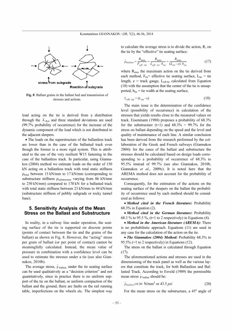
In reality, in a railway line under operation, the seat-
ing surface of the tie is supported on discrete points
(points of contact between the tie and the grains of the
ballast) as shown in Fig. 8. However, the “acting” stress
per grain of ballast (or per point of contact) cannot be
meaningfully calculated. Instead, the mean value of
pressure in combination with a confidence level can be
used to estimate the stresses under a tie (see also Gian-
nakos, 2010b).
The average stress, ballast, under the tie seating surface
can be used qualitatively as a “decision criterion” and not
quantitatively, since in practice there is no uniform sup-
port of the tie on the ballast, or uniform compaction of the
ballast and the ground, there are faults on the rail running
table, imperfections on the wheels etc. The simplest way
to calculate the average stress is to divide the action, R, on
the tie by the “effective” tie seating surface:
(17)
where Rmax the maximum action on the tie derived from
each method, Ftie= effective tie seating surface, Ltie = tie
length, e = track gauge, Leff-tie calculated from Equation
(18) with the assumption that the center of the tie is unsup-
ported, btie = tie width at the seating surface,
(18)
The main issue is the determination of the confidence
level (possibility of occurrence) in calculation of the
stresses that yields results close to the measured values on
track. Eisenmann (1988) proposes a probability of 68.3%
for the substructure (t=1) and 68.3% ÷ 99.7% for the
stress on ballast depending on the speed and the level and
quality of maintenance of each line. A similar conclusion
has been derived from the research performed by the col-
laboration of the Greek and French railways (Giannakos
2004): for the cases of the ballast and substructure the
stresses should be calculated based on design loads corre-
sponding to a probability of occurrence of 68.3% to
95.5% instead of 99.7% (see also Giannakos, 2010b,
Giannakos et al., 2009c). It is noted here that the
AREMA method does not account for the probability of
occurrence.
Consequently, for the estimation of the actions on the
seating surface of the sleepers on the ballast the probabil-
ity of occurrence used by each method should be consid-
ered as follows:
• Method cited in the French literature: Probability
68.3% in Equation (2).
• Method cited in the German literature: Probability
68.3 % to 95.5 %, (t=1 to 2 respectively) in Equations (4).
• Method in the American literature (AREMA): There
is no probabilistic approach. Equations (11) are used in
any case for the calculation of the action on the tie.
• The Giannakos (2004) Method: Probability 68.3% to
95.5% (=1 to 2 respectively) in Equations (12).
The stress on the ballast is calculated through Equation
(17).
The aforementioned actions and stresses are used in the
dimensioning of the track panel as well as the various lay-
ers that constitute the track, for both Ballastless and Bal-
lasted Track. According to Esveld (1989) the permissible
mean stress ballast should be:
N/mm2 or 43.5 psi (20)
For the mean stress on the substructure, a 45o angle of
A
p
pballastRmax
Feff tie–
-----------------Rmax
Leff tie– btie⋅---------------------------
Rmax
Ltie e–( ) btie⋅-------------------------------= = =
Leff tie– Ltie e–( )=
p
pballast 0.30≤
Fig. 8 Ballast grains in the ballast bed and transmission of
stresses and actions.

Design Loads on Railway Substructure: Sensitivity Analysis of the Influence of the Fastening Stiffness
− 54 −
load distribution is assumed, so at a depth of 350 mm
under the tie’s lower (seating) surface the loaded area is:
Length of loaded area=Length of semi-tie 1300 mm +
350 mm = 1650 mm, Width of loaded area = distance
between the ties 600 mm, Surface of loaded area =
1650 × 600 = 990,000 mm2 [equation (21)].
The Sensitivity Analysis of the mean stress on the
substructure in relation to the total static track stiffness
ρtotal was calculated using the four methods described
above. The results are depicted in Figs. 9 and 10 for the
cases of ballasted and ballastless track, respectively.
Again, very resilient fastenings were considered: W14
fastening with Zw700 Saargummi pad in the case of
ballasted track and W15 fastening with Zwp104 pad in the
case of ballasted track. A 95.5% probability of appearance
is used for the French, German and Giannakos (2004)
methods. A surface of 990,000 mm2 is used for the
application of the load (Equation (21)), derived from an
average height of ballast or CRCP under the seating
surface of the tie of 350 mm.
The Sensitivity Analysis of the mean stress on the sub-
structure in relation to the total static track stiffness ρtotal in
the case of ballasted track (Fig. 1), varies between 0.090
MPa to 0.112 MPa according to the AREMA, German and
French methods and between 0.129 MPa to 0.147 MPa
according to Giannakos (2004) method. The mean stress
on the substructure in the case of ballastless track (Fig.
2a), varies between 0.079 MPa to 0.088 MPa as predicted
from the AREMA and French methods. The German
method yields estimates of mean stress between 0.105
MPa and 0.109 MPa, and Giannakos(2004) method
between 0.153 MPa to 0.156 MPa.
It is noteworthy that in the case of slab track with the
use of very resilient fastenings (ρpad=22.5±2.5 kN/mm) the
stress level is independent of the ρtotal due to the character-
istics of the load-deflection curves of the pads and the
clips of the fastenings (Fig. 10). On the contrary in the
case of the ballasted track the stress on the substructure
increases proportionally to the increase of the total static
stiffness coefficient of the track (Fig. 9). The use of very
resilient fastenings in combination with high quality sub-
structure (i.e. 100% Modified Proctor or 105% Proctor
normal), results in acceptable levels of stresses for the sub-
structure life-cycle and, consequently, for the track behav-
iour under circulation.
Eisenmann & Kaess (1980) report measured stress val-
ues in High Speed ballasted tracks between 0.083 and
0.118 N/mm2. There is no reference for stress measure-
ments on the substructure of the slab track since in this
case stresses are negligible, as is also illustrated by the
theoretical results. Instead, the shear stress between the
slab track layers is examined (Eisenmann et al., 1979).
Leykauf & Mattner (1990) report that the average theoret-
ically calculated values of deflection and reaction are ver-
ified by measurements on track (for both ballasted and
ballastless track). This means that the calculated stresses
are also in agreement with in situ values, since they are
derived by dividing the reaction Rmax by the seating sur-
face of tie.
Fig. 9 Mean stress on substructure in the case of classic
ballasted track equipped with W14 Fastening with pad Zw700
(ρpad=50 kN/mm) in relation to the static total track stiffness
total according to the methods cited in the German, French,
American Literature and Giannakos (2004) method.
Fig. 10 Mean stress on substructure in the case of ballastless
(Slab) track equipped with W15 Fastening with pad Zw104
(ρpad=22.5 kN/mm or 128.5 kips/in) in relation to the static
total track stiffness total according to the methods cited in the
German, French, American Literature and Giannakos (2004)
method.
− 55 −
Konstantinos GIANNAKOS / IJR, 7(2), 46-56, 2014
6. Conclusions
In this paper the loads and stresses acting on the sub-
structure of ballasted and ballastless tracks equipped with
very resilient fastenings are analyzed. Four existing meth-
ods, the AREMA, French, German and Giannakos (2004)
method, are used for the estimation of the loads on the
track. These actions are then used to calculate the mean
stress on the substructure with appropriate confidence lev-
els. A parametric investigation is performed for various
track stiffnesses and the results from the four methods are
compared. The sensitivity analysis was performed for a
fluctuation of the static stiffness coefficient of the sub-
grade between 40 kN/mm and 250 kN/mm and the rele-
vant ρtotal for fastenings W14 for ballasted track and W15
for Slab Track. The mean stress, derived by this analysis,
acting on the substructure of the railway track, is one of
the main factors influencing the dimensioning of the lay-
ers the track and its behavior over time.
References
1. Alias J., (1984). “La voie ferree:”, IIème edition, Eyrolles,
Paris.
2. AREMA, (2005). “Manual for Railway Engineering”.
3. Eisenmann J., (2004). “Die Schiene als Tragbalken”, Eisen-
bahningenieur 5/2004.
4. Eisenmann J., (1988). “Schotteroberbau – Moglichkeiten
und Perspektiven fur dieModerne Bahn”.
5. Eisenmann J., Kaess G., (1980). “Das Verhalten des Schot-
ters unter Belastung”, ETR (29) 3, Darmstadt.
6. Eisenmann J., Duwe B., Lempe Ul., Leykauf G., Steinbeis-
ser L., (1979). "Entwinklung, Bemessung und Erforschung
des schotterlosen Oberbaues “Rheda”, AET (34).
7. Eisenmann J., Leykauf G., Mattner L., (1994). “Vorsläge zur
Erhöhung der Oberbauelastizität”, ETR 43, H 7/8.
8. Esveld C., (1989). “Modern Railway Track”, MRT-Produc-
tions, The Netherlands.
9. Fastenrath Fritz, (1981). “Railroad Track - Theory and Prac-
tice”, Frederic Ungar Pub.Co., New York, part 2, “The Rail
as support and Roadway, theoretical principles and practical
examples”, by J. Eisenmann.
10. fib (International Federation of Concrete), (2006). “Precast
concrete railway track systems”.
11. Giannakos K., (2014). “Actions on a Railway Track, due to
an Isolated Defect”, International Journal of Control and
Automation (IJCA), Vol.7, No.3, p.195-212.
12. Giannakos K., (2011). “Heavy Haul Railway Track Mainte-
nance and Use of Resilient versus Stiff Fastenings”,
approved to be published in TRR/2011 (“Railway Mainte-
nance” Committee), Washington D.C., U.S.A., January 23-
27, TRB 90th Annual Meeting proceedings.
13. Giannakos K., (2010a). “The Use of Strain Attenuating Tie
Pads and its Influence on the Rail Seat Load in Heavy-Haul
Railroads”, ASCE – ASME – AREMA, Joint Rail Confer-
ence JRC-2010, Urbana – Champaign IL, USA, April 27-
29.
14. Giannakos K., (2010b). “Interaction between Superstructure
and Substructure in Railways”, in the Fifth International
Conference on Recent Advances in Geotechnical Earth-
quake Engineering and Soil Dynamics and Symposium in
honor of professor I. M. Idriss, San Diego, CA - USA, May
24-29, proceedings.
15. Giannakos K., (2010c). “Loads on track, Ballast Fouling and
Life-cycle under Dynamic Loading in Railways”, Journal of
Transportation Engineering, ASCE, approved to be pub-
lished in the Journal, electronically published DOI: 10.1061/
(ASCE)TE.1943-5436.0000182, Vol. 136, Issue 12, Decem-
ber, pp. 1075-1084.
16. Giannakos K., Tsoukantas S., (2010d). “Requirements for
Stiffness Variation between Slab and Ballasted Railway
Track and Resulting Design Loads”, ICASTOR (Indian Cen-
tre For Advanced Scientific and Technological Research)
Journal for Engineering, January 2010c, Vol. 3, No. 1, pp. 21
-35.
17. Giannakos K., Tsoukantas S., (2009a). “Transition Zone
between Slab Track and Ballasted - Variation of Elasticity
and Influence on the Acting Forces”, Greek Department of
Concrete (Member of FIB – RILEM), Conference, Limassol
Cyprus, 24-27 October, Proceedings.
18. Giannakos K., (2009b) “Selected Topics on Railways”, Uni-
versity of Thessaly Greece, Department of Civil Engineer-
ing, Volos.
19. Giannakos A., Loizos A., 2009c, “Actions on Railway Track
Panel and Ballast - Behavior of the Hellenic limestone bal-
last”, 8th International Conference on the Bearing Capacity
of Roads, Railways and Airfields, 29 June–2 July, Cham-
paign-Urbana, Illinois, USA, Proceedings.
20. Giannakos K., Loizos A., (2009d). “Evaluation of actions on
concrete sleepers as design loads–Influence of fastenings”,
International Journal of Pavement Engineering (IJPE),
November 2009, DOI: 10.1080/10298430903402161, Vol.
11, Issue 3 June 2010, pp. 197-213.
21. Giannakos K., Obermeyer Planen + Beraten Gmbh, (2008).
“Calculation of Stiffness coefficients, in the Transition Zone
between Slab Track and Ballasted Track – Slab Track Rheda
2000 type Design of the New Railway Track of Normal
Gauge in the Kiato – km 2+000 position (Rododaphne)”, for
ERGA-OSE, Athens.
22. Giannakos K., (2004). “Actions on Railway Track”, Papazis-
sis publications, Athens, English edition, www.papazisi.gr.
23. Hay W., (1982). “Railroad Engineering”, John Wiley &
Sons.
24. Leykauf G., Mattner L., (1990). “Elastisches Verformungs-
verhalten des Eisenbahnoberbaus – Eigenschaften und
Anforderungen”, Eisenbahningenieur 41 (1990) 3.
25. ORE/UIC, Question D117, Rp2, (1973). “Study of the
change in the track level as a function of the traffic and of

Design Loads on Railway Substructure: Sensitivity Analysis of the Influence of the Fastening Stiffness
− 56 −
the track components (First results of laboratory and site
tests)”, April 1.
26. ORE/UIC, Question D117, Rp2, (1974). “Rheological prop-
erties of the track”, April 1.
27. Prud’ homme A., Erieau, J., (1976). “Les nouvelles traverses
en beton de la SNCF”, RGCF-2.
28. R.G.C.F. (Revue Generale des Chemins de Fer), Comite de
redaction, (1973). “Sollicitations de la Voie, du Ballast et de
la Plate-forme”, Mai.
29. Tsoukantas S., Giannakos K., Topintzis T., Zois H., (2006).
“System Rheda 2000 from the point of view of a Structural
Engineer – the most modern evolution of superstructure
technology in Railway projects”, Greek Department of Con-
crete, Alexandroupolis, 24-27 October, Proceedings.
30. Tsoukantas S., 1999, “Investigation of Problems concerning
the Slab Track application in Greece in tunnels, plain line
and bridges”, (Research Program of OSE-ERGOSE)”, Ath-
ens.
31. U.I.C. (International Union of Railways), fiche UIC (Code)
719R, 1994, “Earthworks and track-bed layers for railway
lines”, 1-1-1994.