design guidelines for subdivisional developments, urban and rural ...
29
DESIGN GUIDELINES FOR SUBDIVISIONAL DEVELOPMENTS, URBAN AND RURAL ROAD AND DRAINAGE CONSTRUCTION PROJECTS AND TRAFFIC MANAGEMENT PREPARED BY: MITCHELL ASSETS UNIT Jan 2006 Mitchell Shire – Design Guidelines 1.0 – Jan 2006 page 1
Transcript of design guidelines for subdivisional developments, urban and rural ...
DESIGN GUIDELINES FOR
SUBDIVISIONAL DEVELOPMENTS,
URBAN AND RURAL ROAD AND DRAINAGE CONSTRUCTION PROJECTS AND TRAFFIC
MANAGEMENT
PREPARED BY: MITCHELL ASSETS UNIT Jan 2006
Mitchell Shire – Design Guidelines 1.0 – Jan 2006 page 1
Table of Contents Section Page No. Forward 1.0 Objectives 4 2.0 Subdivision Standards 5 3.0 General Design Requirements 15 4.0 Specific Design Requirements 16 5.0 Design presentation 17 6.0 Detailed Design requirements 18 7.0 Intersection designs 24 8.0 Drainage Design 26
Appendix A 29
Mitchell Shire – Design Guidelines 1.0 – Jan 2006 page 2

Forward The Design Guidelines for Subdivisional Development Urban and Rural Road and Drainage Construction Projects and Traffic management, hereinafter called the Design Guidelines, are intended as a reference to designers to guide and assist them in the preparation of best practice designs for civil engineering infrastructure to be constructed in the Shire. The Design Guidelines provide a set of Subdivisional Standards that will be used by developers, consultants and designers in the planning of new infrastructure for residential and industrial developments throughout the Shire. Designers are required to have a good knowledge of the list of Standards and Publications listed in Section 3.0. It is intended that the Design Guidelines will be updated on a regular basis and comment and feedback on the contents will be welcomed.
Mitchell Shire – Design Guidelines 1.0 – Jan 2006 page 3
1.0 OBJECTIVES The overall objectives of the Design Guidelines are: • To provide sufficient information and direction to designers, to ensure that all
issues associated with the safe and efficient movement of road traffic are addressed.
• To provide a set of guidelines for use by Mitchell Shire and external
consultants for the preparation of quality engineering design plans for road and drainage construction projects and traffic engineering projects.
• To provide a set of design standards for use in planning new subdivisional
developments, on a uniform basis throughout the Mitchell Shire. • To provide the basis for Specification to be used for outsourcing the design of
various capital works, and for Panel Contracts.
Mitchell Shire – Design Guidelines 1.0 – Jan 2006 page 4

2.0 SUBDIVISIONAL STANDARDS This section provides engineering design standards for new subdivisional/planning permit developments requiring vehicle access, drainage, traffic management and pedestrian facilities. The design standards are also applicable to existing developments where road and pedestrian access has not been fully constructed and are being upgraded. All new access and/or through roads and ancillary works within new subdivision developments shall generally be provided at full cost to the developer in accordance with the standards set out in the following sections. In certain cases developments may be subject to Development Contribution Plans under the planning Act. These issues will need to be addressed by the Shires Economic Development Department early on in the planning process. Developments that set out allotments abutting unmade partially constructed roads will be required to upgrade that road to a standard not less than the criteria set out in this section. A contribution from the developer will be required for this work and will generally be based on the following criteria: • Road Function • Benefit to developer • Benefit to Council • Estimated volume of traffic using road – before and after the development. • Road and pedestrian safety issues and amenity of surrounding area. Subject to Council agreeing to a contribution, a decision regarding the timing of construction of such unmade roads should be made after due consideration by Council with respect to availability of funding.
Mitchell Shire – Design Guidelines 1.0 – Jan 2006 page 5
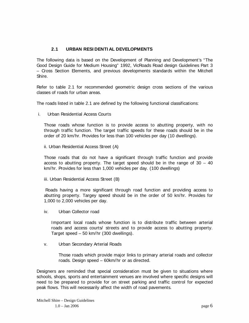
2.1 URBAN RESIDENTIAL DEVELOPMENTS The following data is based on the Development of Planning and Development’s “The Good Design Guide for Medium Housing” 1992, VicRoads Road design Guidelines Part 3 – Cross Section Elements, and previous developments standards within the Mitchell Shire. Refer to table 2.1 for recommended geometric design cross sections of the various classes of roads for urban areas. The roads listed in table 2.1 are defined by the following functional classifications: i. Urban Residential Access Courts
Those roads whose function is to provide access to abutting property, with no through traffic function. The target traffic speeds for these roads should be in the order of 20 km/hr. Provides for less than 100 vehicles per day (10 dwellings). ii. Urban Residential Access Street (A) Those roads that do not have a significant through traffic function and provide access to abutting property. The target speed should be in the range of 30 – 40 km/hr. Provides for less than 1,000 vehicles per day. (100 dwellings) iii. Urban Residential Access Street (B) Roads having a more significant through road function and providing access to abutting property. Targey speed should be in the order of 50 kn/hr. Provides for 1,000 to 2,000 vehicles per day. iv. Urban Collector road
Important local roads whose function is to distribute traffic between arterial roads and access courts/ streets and to provide access to abutting property. Target speed – 50 km/hr (300 dwellings).
v. Urban Secondary Arterial Roads
Those roads which provide major links to primary arterial roads and collector roads. Design speed – 60km/hr or as directed.
Designers are reminded that special consideration must be given to situations where schools, shops, sports and entertainment venues are involved where specific designs will need to be prepared to provide for on street parking and traffic control for expected peak flows. This will necessarily affect the width of road pavements.
Mitchell Shire – Design Guidelines 1.0 – Jan 2006 page 6
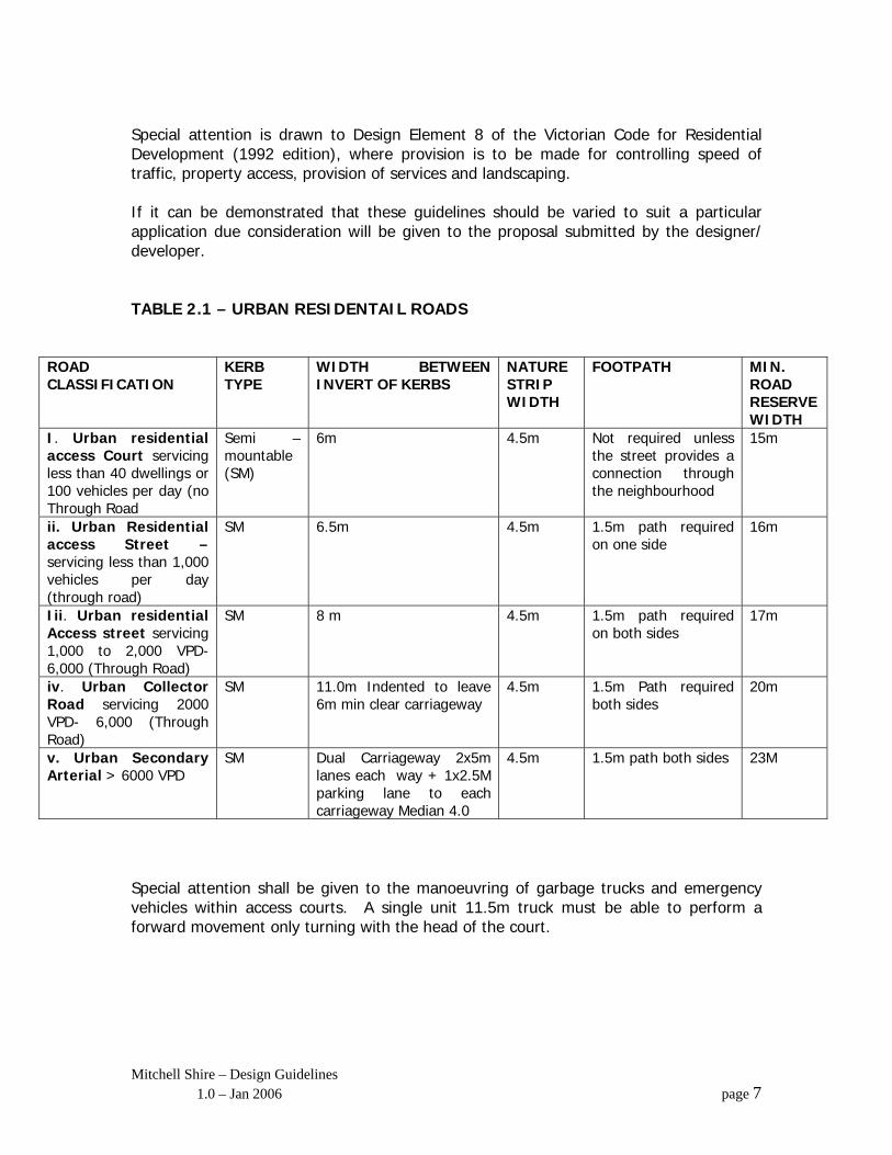
Special attention is drawn to Design Element 8 of the Victorian Code for Residential Development (1992 edition), where provision is to be made for controlling speed of traffic, property access, provision of services and landscaping. If it can be demonstrated that these guidelines should be varied to suit a particular application due consideration will be given to the proposal submitted by the designer/ developer. TABLE 2.1 – URBAN RESIDENTAIL ROADS
ROAD CLASSIFICATION
KERB TYPE
WIDTH BETWEEN INVERT OF KERBS
NATURE STRIP WIDTH
FOOTPATH MIN. ROAD RESERVE WIDTH
I. Urban residential access Court servicing less than 40 dwellings or 100 vehicles per day (no Through Road
Semi – mountable (SM)
6m 4.5m Not required unless the street provides a connection through the neighbourhood
15m
ii. Urban Residential access Street –servicing less than 1,000 vehicles per day (through road)
SM 6.5m 4.5m 1.5m path required on one side
16m
Iii. Urban residential Access street servicing 1,000 to 2,000 VPD- 6,000 (Through Road)
SM 8 m 4.5m 1.5m path required on both sides
17m
iv. Urban Collector Road servicing 2000 VPD- 6,000 (Through Road)
SM 11.0m Indented to leave 6m min clear carriageway
4.5m 1.5m Path required both sides
20m
v. Urban Secondary Arterial > 6000 VPD
SM Dual Carriageway 2x5m lanes each way + 1x2.5M parking lane to each carriageway Median 4.0
4.5m 1.5m path both sides 23M
Special attention shall be given to the manoeuvring of garbage trucks and emergency vehicles within access courts. A single unit 11.5m truck must be able to perform a forward movement only turning with the head of the court.
Mitchell Shire – Design Guidelines 1.0 – Jan 2006 page 7

Pavements The depths of flexible pavements, in all cases, are to be determined in accordance with AustRoads guidelines for pavement design and based on a design life of 25 years (min). The Sub grade CBR and other geotechnical tests are required to verify the suitability of the sub grade to support the proposed pavement depths. Other pavement surfaces such as interlocking segmental concrete paving or reinforced concrete paving will be acceptable subject to compliance with appropriate industry standards for such materials, and colour schemes/layouts etc to be approved by the Shire. The base course pavement material will consist of class 2 crushed rock and subbase course material will generally consist of class 3 crushed rock. The subgrade material may require lime and/or cement stabilisation. Kerb Types The recommended kerb type is a semi-mountable kerb as in standard drawing MSC 101. There may be situations where the use of a barrier type kerb (MSC 101) is more appropriate and use of such kerbs will be permitted, subject to approval. Wearing Surface The wearing surface is to consist of a 7mm primer seal or bituminous prime and a 50mm thickness of hot mix asphalt, size 10, of appropriate design to suit each particular case. (eg lightly trafficked street, roundabouts, etc) Traffic Speeds and Intersection Design Where local Area Traffic management (LATM) devices are required to control target traffic speeds, designers are required to comply with provisions of Vic Roads Traffic Engineering Manual Vol 1 – Traffic Management. For intersection designs, designers are required to comply with Section 3 of the Traffic Engineering Manual. Vehicle Crossing A vehicle crossing is to provide to each allotment with dimensions in accordance with Councils standard drawings. Where crossings are proposed to be located within 10m of an intersection, the designer must have further discussion with Shire, for determination. Crossings shall not be located over drainage side entry pits or any other service pits. The applicable standard drawings are MSC 307 and MSC 308.
Mitchell Shire – Design Guidelines 1.0 – Jan 2006 page 8
Drainage Each allotment is to provided with a pipe drainage outlet at the legal point of discharge and the outlet shall be connected to a pipe drain. Easement drains are to be provided within allotments and/or reserves to pick up stormwater from these areas that cannot be drained to a street drain. Appropriate drainage easements are to be set aside. All drainage from new developments shall be connected to an approved outfall drainage system via an underground pipe drain. The applicable standard drawings are MSC 209. Refer to Section 8.0 for design Standards. Footpaths Where required provide 1500mm wide concrete, 100mm thick (using N20 concrete) footpaths. Back of path to be generally located 300mm from the title boundary. The applicable standard Drawings are MSC 401 & 402. Nature Strips – Residential areas Nature strips are required to be top soiled and grassed in accordance with Mitchell Shire landscape Standards and trees are to be provided in accordance with Shire requirements. The minimum depth of topsoil is to be 150mm. The applicable standard drawings are MSC C709. Road Furniture Provide street name signs, Statcon signs, and all other necessary road traffic signs and road markings in accordance with Australian Standard AS 1742 and Mitchell Shire Standards. Council Reserves All reserves within the development shall be landscaped in accordance with plans to be approved by the Shire. 2.4m concrete paths, 100mm thick, reinforced with F52 mesh, are to be provided where it is necessary to link proposed and existing pedestrian routes. Public lighting to B2 Standard (AS 1158) is to be provided along the route of the footpath, with all cabling to be underground. The Shire has designated standard poles for specific areas throughout the Shire. The standards must be observed.
Mitchell Shire – Design Guidelines 1.0 – Jan 2006 page 9

Reserves shall be graded and drained to underground pipe drainage systems and shall be provided with cut off drains to prevent water flowing into properties.
Mitchell Shire – Design Guidelines 1.0 – Jan 2006 page 10
Street Lighting Street lighting shall be provided for all new urban roads in accordance with Australian Standard AS1158 – Roadway Lighting and the requirements of the Shire’s provider of street lighting.
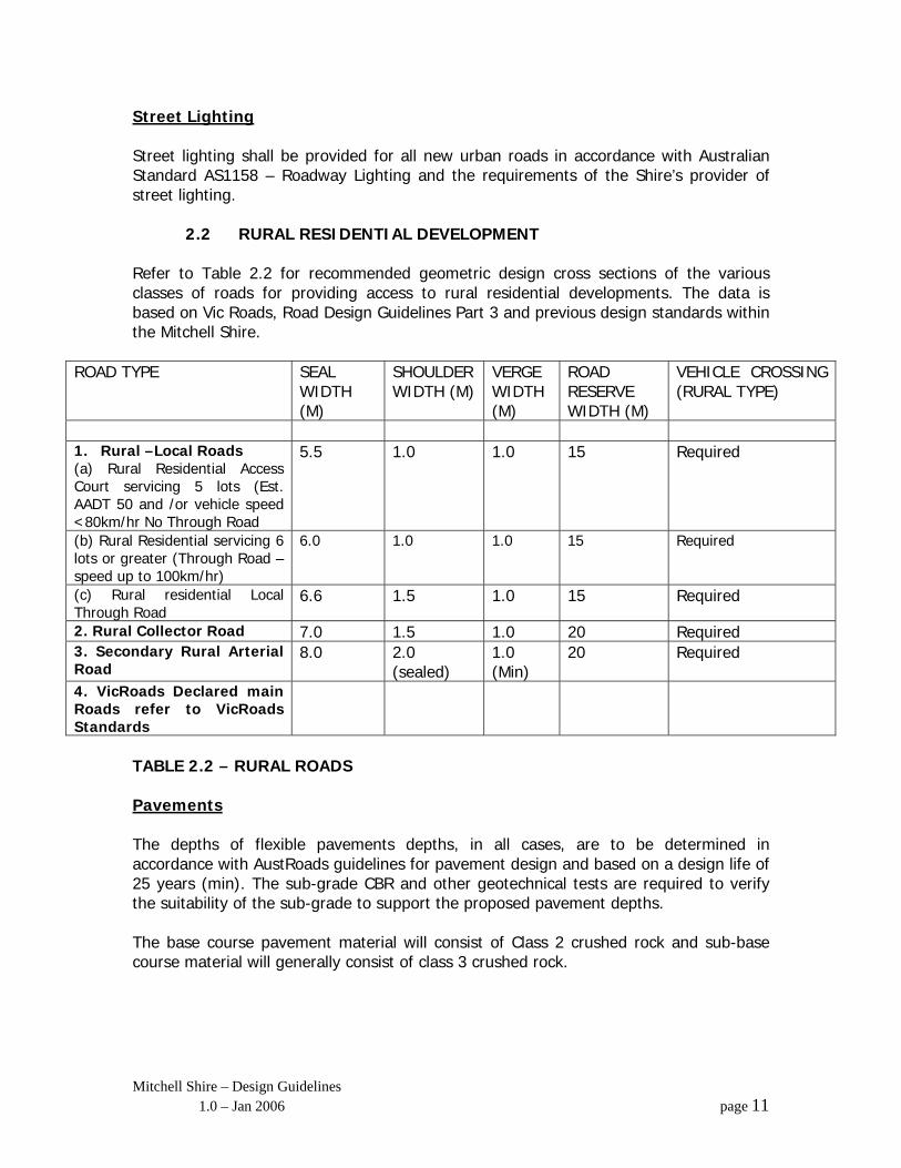
2.2 RURAL RESIDENTIAL DEVELOPMENT Refer to Table 2.2 for recommended geometric design cross sections of the various classes of roads for providing access to rural residential developments. The data is based on Vic Roads, Road Design Guidelines Part 3 and previous design standards within the Mitchell Shire.
ROAD TYPE SEAL WIDTH (M)
SHOULDER WIDTH (M)
VERGE WIDTH (M)
ROAD RESERVE WIDTH (M)
VEHICLE CROSSING (RURAL TYPE)
1. Rural –Local Roads (a) Rural Residential Access Court servicing 5 lots (Est. AADT 50 and /or vehicle speed <80km/hr No Through Road
5.5 1.0 1.0 15 Required
(b) Rural Residential servicing 6 lots or greater (Through Road – speed up to 100km/hr)
6.0 1.0 1.0 15 Required
(c) Rural residential Local Through Road
6.6 1.5 1.0 15 Required
2. Rural Collector Road 7.0 1.5 1.0 20 Required 3. Secondary Rural Arterial Road
8.0 2.0 (sealed)
1.0 (Min)
20 Required
4. VicRoads Declared main Roads refer to VicRoads Standards
TABLE 2.2 – RURAL ROADS Pavements The depths of flexible pavements depths, in all cases, are to be determined in accordance with AustRoads guidelines for pavement design and based on a design life of 25 years (min). The sub-grade CBR and other geotechnical tests are required to verify the suitability of the sub-grade to support the proposed pavement depths. The base course pavement material will consist of Class 2 crushed rock and sub-base course material will generally consist of class 3 crushed rock.
Mitchell Shire – Design Guidelines 1.0 – Jan 2006 page 11

Wearing Surface 25mm size 7 Wearing Course Asphalt 170. 25mm size 10 Base Core Asphalt 170.
• The base course is to be primed with a bituminous prime coat and sprayed with a size stone chip seal. Prevailing weather conditions will influence the use of a prime coat.
A size 7 primer seal may be used in lieu of a prime coat, however a final size 10 seal is to be applied within 6-9 months of the primer seal. Vehicle Crossings A Shire standard rural type vehicle crossing is to be provided to each allotment. Special care shall be given to the location of the crossings to comply with site distance requirements (refer to Section 6.7) The applicable standard drawings are MSC 306, MSC 308 Shoulders Road shoulders shall be constructed from the same materials and depths as for the sealed pavement. Drainage Provide table drainage and culverts as necessary to ensure the road reserve is drained to appropriate outfall. Provide catch pits and scour control measures to ensure open channels are not subjected to erosion. Provide all necessary drainage easements. Refer to Section 8.0 for Design Standards. Road Furniture Provide and install road signage, guide post delineation, street name signs and line marking as required in accordance with Australian Standard AS 1742.
2.3 INDUSTRIAL DEVELOPMENTS The minimum pavement width for roads servicing new industrial development shall be 12.0m between line and kerbs. The kerb type shall be semi-mountable, 600mm wide in accordance with Standards Drawings MSC. The pavement depth shall be designed after due consideration of a geotechnical investigation carried out by a qualified geo-technical engineer. The design life for these roads is to be 50 years. The minimum thickness of the type H hot mix asphalt shall be 80mm.
Mitchell Shire – Design Guidelines 1.0 – Jan 2006 page 12

Heavy -duty reinforced concrete crossings shall be provided to each allotment. The crossings are to be designed to provide for the largest “design vehicle” expected to enter the allotment. Special consideration must be given to intersection designs to provide for the safe movement of 25m semi-trailers and B –Doubles (if appropriate)
Mitchell Shire – Design Guidelines 1.0 – Jan 2006 page 13
Fees Refer to Appendix “C” for details of fees applicable to engineering plan preparation, supervision of works and checking of plans. Design Plans Engineering design plans shall be prepared by qualified professionals in accordance with these Design Guidelines and submitted to the Shire for approval prior to commencement of works. Approvals Refer to Appendix D for details of Mitchell Shire procedures for the checking and approvals of engineering plans for subdivisions.
Mitchell Shire – Design Guidelines 1.0 – Jan 2006 page 14
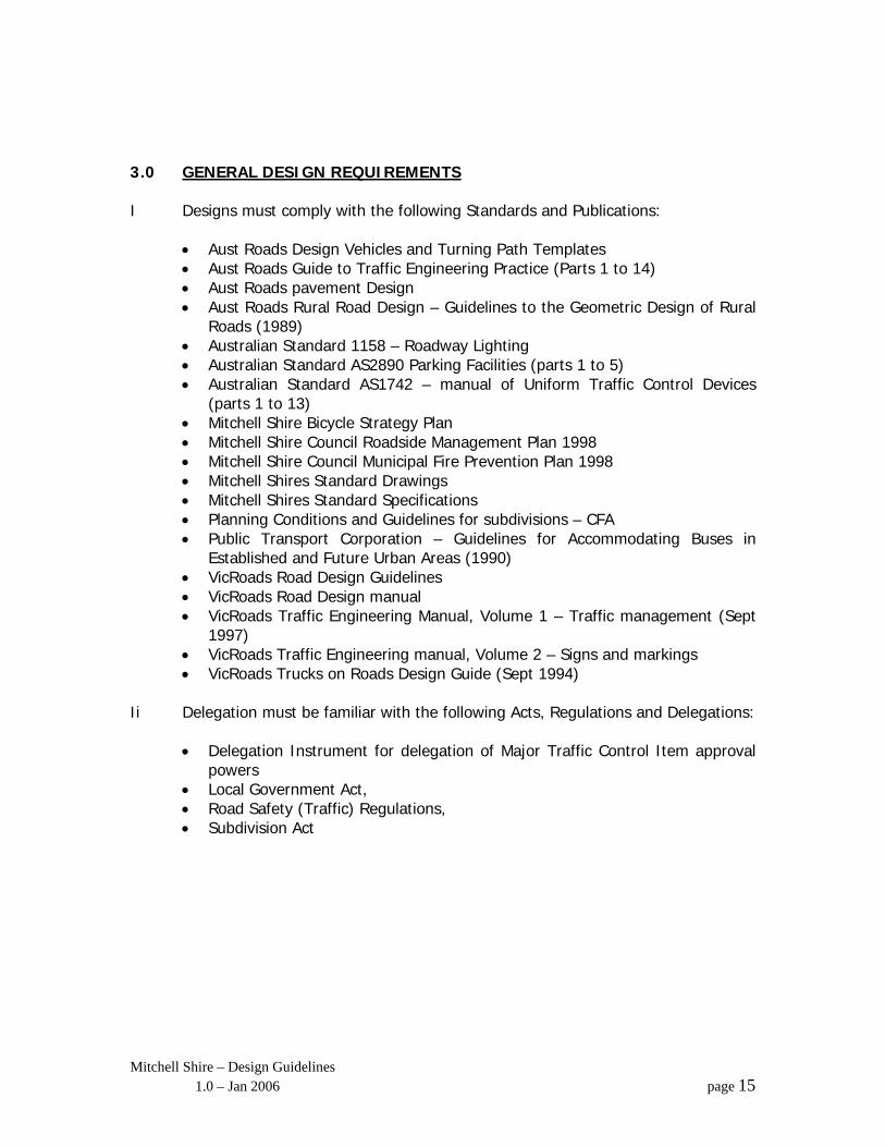
3.0 GENERAL DESIGN REQUIREMENTS I Designs must comply with the following Standards and Publications:
• Aust Roads Design Vehicles and Turning Path Templates • Aust Roads Guide to Traffic Engineering Practice (Parts 1 to 14) • Aust Roads pavement Design • Aust Roads Rural Road Design – Guidelines to the Geometric Design of Rural
Roads (1989) • Australian Standard 1158 – Roadway Lighting • Australian Standard AS2890 Parking Facilities (parts 1 to 5) • Australian Standard AS1742 – manual of Uniform Traffic Control Devices
(parts 1 to 13) • Mitchell Shire Bicycle Strategy Plan • Mitchell Shire Council Roadside Management Plan 1998 • Mitchell Shire Council Municipal Fire Prevention Plan 1998 • Mitchell Shires Standard Drawings • Mitchell Shires Standard Specifications • Planning Conditions and Guidelines for subdivisions – CFA • Public Transport Corporation – Guidelines for Accommodating Buses in
Established and Future Urban Areas (1990) • VicRoads Road Design Guidelines • VicRoads Road Design manual • VicRoads Traffic Engineering Manual, Volume 1 – Traffic management (Sept
1997) • VicRoads Traffic Engineering manual, Volume 2 – Signs and markings • VicRoads Trucks on Roads Design Guide (Sept 1994)
Ii Delegation must be familiar with the following Acts, Regulations and Delegations:
• Delegation Instrument for delegation of Major Traffic Control Item approval powers
• Local Government Act, • Road Safety (Traffic) Regulations, • Subdivision Act
Mitchell Shire – Design Guidelines 1.0 – Jan 2006 page 15

4.0 SPECIFIC DESIGN REQUIREMENTS VI. For projects designed by Mitchell Infrastructure Unit staff, the designer shall
comply with the procedures. vii. For external contract work the Designer shall conform to the Specification for the design work as advertised, including attendance at specified meetings to ensure the design is processing satisfactorily, throughout all stages of the process. Refer to Appendix B for Stage Details.
Mitchell Shire – Design Guidelines 1.0 – Jan 2006 page 16
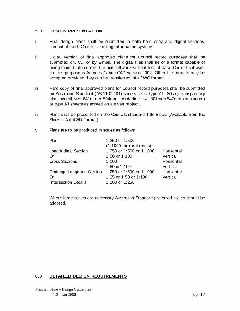
5.0 DESIGN PRESENTATION i. Final design plans shall be submitted in both hard copy and digital versions,
compatible with Council’s existing information systems. ii. Digital version of final approved plans for Council record purposes shall be
submitted on, CD, or by E-mail. The digital files shall be of a format capable of being loaded into current Council software without loss of data. Current software for this purpose is Autodesk’s AutoCAD version 2002. Other file formats may be accepted provided they can be transferred into DWG format.
iii. Hard copy of final approved plans for Council record purposes shall be submitted
on Australian Standard (AS 1100.101) sheets sizes Type A1 (80sm) transparency film, overall size 841mm x 594mm, borderline size 801mmx547mm (maximum) or type A3 sheets as agreed on a given project.
iv. Plans shall be presented on the Councils standard Title Block. (Available from the
Shire in AutoCAD Format). v. Plans are to be produced in scales as follows:
Plan 1:250 or 1:500 (1:1000 for rural roads) Longitudinal Section 1:250 or 1:500 or 1:1000 Horizontal Or 1:50 or 1:100 Vertical Cross Sections 1:100 Horizontal 1:50 or1:100 Vertical Drainage Longitude Section 1:250 or 1:500 or 1:1000 Horizontal Or 1:25 or 1:50 or 1:100 Vertical Intersection Details 1:100 or 1:250 Where large scales are necessary Australian Standard preferred scales should be adopted.
6.0 DETAILED DESIGN REQUIREMENTS
Mitchell Shire – Design Guidelines 1.0 – Jan 2006 page 17

6.1 PLAN
It is important to note that in some projects, it will be necessary to produce more than one plan. This is particularly the case for projects such as intersection designs and CBD landscape works. The projects Co-ordinator must be consulted to determine the level of information to be shown on each plan. For intersection treatments, it will be usual practice to show existing and design contours, set out points, radii and outline of proposed works and existing features on one plan and detailed presentation of all proposed works and existing features on another plan. The plan shall clearly show: • All existing features, including existing road and drainage construction, trees,
fences, structures, etc. • Property details including boundaries (Lot number, dimensions, PS number,
street numbers etc. • All pavements and ancillary works that are to be constructed. • Design centre lines with chainages at intervals generally ranging from 10m to
20m to suite local conditions such as terrain and curvature. Chainages of pits, tangent points, property boundaries, low points and culverts shall also be shown.
• All service Authorities, mains and assets. (Depth of service to be noted where excavation is likely to interfere with service).
• Intersection contours at 0.1m intervals • Service conduit positions. • Stormwater drains, sub-surface drains, property drain connections, drainage
structures, pits, end walls and pit schedule. • Offsets to drainage lines. • Extent and limits of proposed works including connections to existing
construction. • Design line of kerb or edges of seal/formation and horizontal alignment. • Street lighting layout and underground and/or overhead power supply. • Set out co-ordinates and levels. • Signage, line marking, major traffic control signage – full details of type,
location and quality of signs are to be shown. (permanent and temporary) • Footpaths, vehicle and path crossings. • Location of all survey stations, PSM’s and TBM’s and reduced levels.
6.1 PLAN (Cont)
Mitchell Shire – Design Guidelines 1.0 – Jan 2006 page 18
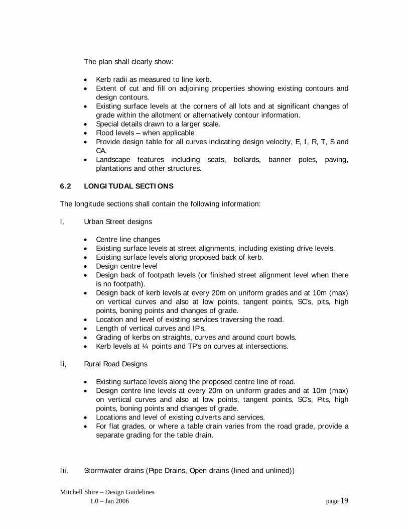
The plan shall clearly show: • Kerb radii as measured to line kerb. • Extent of cut and fill on adjoining properties showing existing contours and
design contours. • Existing surface levels at the corners of all lots and at significant changes of
grade within the allotment or alternatively contour information. • Special details drawn to a larger scale. • Flood levels – when applicable • Provide design table for all curves indicating design velocity, E, I, R, T, S and
CA. • Landscape features including seats, bollards, banner poles, paving,
plantations and other structures. 6.2 LONGITUDAL SECTIONS The longitude sections shall contain the following information: I, Urban Street designs
• Centre line changes • Existing surface levels at street alignments, including existing drive levels. • Existing surface levels along proposed back of kerb. • Design centre level • Design back of footpath levels (or finished street alignment level when there
is no footpath). • Design back of kerb levels at every 20m on uniform grades and at 10m (max)
on vertical curves and also at low points, tangent points, SC’s, pits, high points, boning points and changes of grade.
• Location and level of existing services traversing the road. • Length of vertical curves and IP’s. • Grading of kerbs on straights, curves and around court bowls. • Kerb levels at ¼ points and TP’s on curves at intersections.
Ii, Rural Road Designs
• Existing surface levels along the proposed centre line of road. • Design centre line levels at every 20m on uniform grades and at 10m (max)
on vertical curves and also at low points, tangent points, SC’s, Pits, high points, boning points and changes of grade.
• Locations and level of existing culverts and services. • For flat grades, or where a table drain varies from the road grade, provide a
separate grading for the table drain. Iii, Stormwater drains (Pipe Drains, Open drains (lined and unlined))
Mitchell Shire – Design Guidelines 1.0 – Jan 2006 page 19
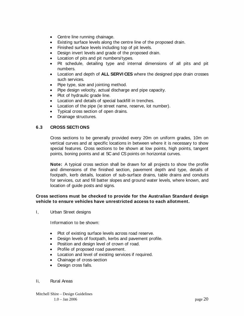
• Centre line running chainage. • Existing surface levels along the centre line of the proposed drain. • Finished surface levels including top of pit levels. • Design invert levels and grade of the proposed drain. • Location of pits and pit numbers/types. • Pit schedule, detailing type and internal dimensions of all pits and pit
numbers. • Location and depth of ALL SERVICES where the designed pipe drain crosses
such services. • Pipe type, size and jointing method. • Pipe design velocity, actual discharge and pipe capacity. • Plot of hydraulic grade line. • Location and details of special backfill in trenches. • Location of the pipe (ie street name, reserve, lot number). • Typical cross section of open drains. • Drainage structures.
6.3 CROSS SECTIONS
Cross sections to be generally provided every 20m on uniform grades, 10m on vertical curves and at specific locations in between where it is necessary to show special features. Cross sections to be shown at low points, high points, tangent points, boning points and at SC and CS points on horizontal curves. Note: A typical cross section shall be drawn for all projects to show the profile and dimensions of the finished section, pavement depth and type, details of footpath, kerb details, location of sub-surface drains, table drains and conduits for services, cut and fill batter slopes and ground water levels, where known, and location of guide posts and signs.
Cross sections must be checked to provide for the Australian Standard design vehicle to ensure vehicles have unrestricted access to each allotment. I, Urban Street designs Information to be shown:
• Plot of existing surface levels across road reserve. • Design levels of footpath, kerbs and pavement profile. • Position and design level of crown of road. • Profile of proposed road pavement. • Location and level of existing services if required. • Chainage of cross-section • Design cross falls.
Ii, Rural Areas
Mitchell Shire – Design Guidelines 1.0 – Jan 2006 page 20
• Plot of existing surface levels across the road reserve. • Design levels and plot of centre line, edges of seal, shoulders, verges and
table drain. • Profile of proposed road pavement and shoulders. • Extent of batters and drains. • Property lines, fences and other structures that may be located within the
road reserve. • Plot of existing or proposed drainage culvert at the relevant cross-section. • Design cross falls.
6.4 INTERSECTION AND COURT BOWL DETAILS
Information to be shown: • Appropriate existing and proposed features. • Kerbs, vehicle crossings, pedestrian crossing and footpaths. • Design contours of road pavement at 0.1m intervals. • Chainage along line kerb. • Levels at TP’s, along crown of road and crown high point in Court bowl and
at 11/4 points around kerb returns.
• Radii of all curves on line of kerb. • Location of stormwater drains, pits and drainage structures. • Services. • Signage details. • Landscaping and Street Furniture.
6.5 VERTICAL ALIGNMENT
Mitchell Shire – Design Guidelines 1.0 – Jan 2006 page 21
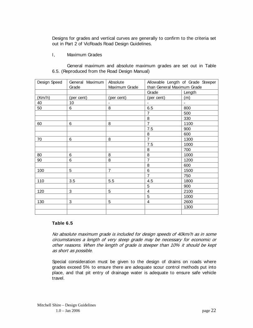
Designs for grades and vertical curves are generally to confirm to the criteria set out in Part 2 of VicRoads Road Design Guidelines. I, Maximum Grades General maximum and absolute maximum grades are set out in Table 6.5. (Reproduced from the Road Design Manual)
Design Speed General Maximum Grade
Absolute Maximum Grade
Allowable Length of Grade Steeper than General Maximum Grade
Grade Length (Km/h) (per cent) (per cent) (per cent) (m) 40 10 - - - 50 6 8 6.5 800 7 500 8 330 60 6 8 7 1100 7.5 900 8 600 70 6 8 7 1300 7.5 1000 8 700 80 6 8 8 1000 90 6 8 7 1200 8 600 100 5 7 6 1500 7 750 110 3.5 5.5 4.5 1800 5 900 120 3 5 4 2100 5 1000 130 3 5 4 2600 1300
Table 6.5 No absolute maximum grade is included for design speeds of 40km/h as in some circumstances a length of very steep grade may be necessary for economic or other reasons. When the length of grade is steeper than 10% it should be kept as short as possible. Special consideration must be given to the design of drains on roads where grades exceed 5% to ensure there are adequate scour control methods put into place, and that pit entry of drainage water is adequate to ensure safe vehicle travel.
Mitchell Shire – Design Guidelines 1.0 – Jan 2006 page 22
Ii, Minimum Grades Drainage is the main consideration where minimum grades are involved. In rural areas a minimum grade of 1:200 (0.5) is desirable to provide for adequate drainage of table and median drains. Where this cannot be achieved in very flat terrain, special consideration shall be given to cross falls of the pavement and grading of table drains to ensure the pavement boxing is above the water table. In urban areas or where kerbs are provided the absolute minimum of 1 in 200 (0.5%) Refer to Section 2.5.7 of VicRoads Design Guidelines Part 2 for criteria involving the design of vertical curves. Special consideration shall be given to drainage where vertical curves are used on relatively flat grades.
6.6 HORIZONTAL ALIGNMENT
Refer to Section 2.4 of Vic Roads Guidelines Part 2, for criteria involving horizontal alignment. It will be essential that designers prepare horizontal alignments to provide for designated speed controls and target speed controls, particularly in residential areas. Refer to Victorian Code for Residential Development for recommended target speeds for various circumstances
6.7 SIGHT DISTANCE
The designer shall check and provide for the following sight distances along roadways having regard to the applicable speed limit: • Car stopping Sight Distance • Truck Stopping Sight Distance • Overtaking Sight Distance • Manoeuvre Sight Distance
At intersections the following sight distances on all approach roads are to be checked and comply with requirements as set down in Section 2.3 of Vic Roads Design Guidelines Part 2: • Approach Sight Distance • Safe Intersection Sight Distance • Truck Stopping Sight Distance • Tail Light Stopping Distance
Mitchell Shire – Design Guidelines 1.0 – Jan 2006 page 23
7.0 INTERSECTIONS
For the purpose of these guidelines it is assumed that the type of intersection to be designed has clearly been decided upon as part of an earlier investigation and planning process, including any necessary land acquisitions. Designers must provide for the safe and efficient movement of traffic of traffic and also provide for the safety of pedestrians and cyclists. A strong emphasis must be placed on the correct number and placement of road markings and signage and also pay special attention to the overall landscape /amenity of the intersection. The following references are to be used in conjunction with the Vic Roads Traffic Engineering manual Vol 1 – Traffic Management. • Vic Roads Traffic Engineering manual Vol 2, Signs and Markings • Aust Roads “Guide to Traffic Engineering Practice-
Par 5, Intersections at Grade Part 6, Roundabouts Part 7, Traffic Signals
• Australian Standard 1742 Manual of Uniform Traffic – Control Devices, Part 2 Traffic Control devices for general use part 14 Traffic Signals.
• Vic Roads – Trucks on Roads – Design Guide
7.1 GENERAL DESIGN PARAMETERS
Regardless of the type of intersection being designed the designer must have regard to: • Volume and type of traffic using the intersection with realistic
allowance for increases in traffic volumes over the estimated life of the intersection.
• Safe intersection sight distance • Design Turning Templates for various classes of vehicles at
appropriate design speeds. • Adequate sight distances within roundabouts. • Adequate drainage. • Appropriate lane widths. • Design speed for the intersection – ensure that vehicles are physically
prevented from traversing intersections faster than that recommended safe speed.
• Kerb Types. • Road camber (cross falls) and super elevation – to ensure that heavy
vehicles may negotiate all turns without danger of overturning. • Street lighting.
Each intersection and associated linking roadways must be designed to adequately cater, for all turning movements for the expected types of vehicles and more specifically must be based around a “Design Vehicle” and a “Check Vehicle” as defined in Section 3
Mitchell Shire – Design Guidelines 1.0 – Jan 2006 page 24
of the “Trucks on Roads – Design Guide”. The list of such vehicles is described in table 3.1 of this guide. Designers are required to be familiar with legal requirements set down in the “trucks on Roads – Design Guide”.
Mitchell Shire – Design Guidelines 1.0 – Jan 2006 page 25
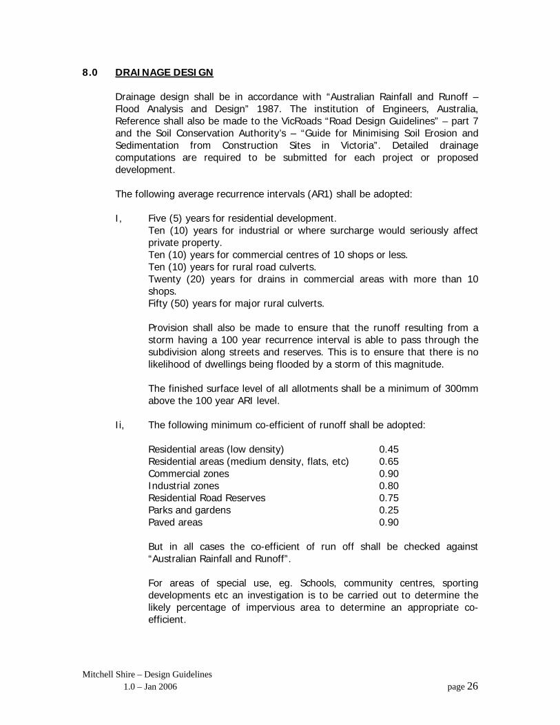
8.0 DRAINAGE DESIGN
Drainage design shall be in accordance with “Australian Rainfall and Runoff – Flood Analysis and Design” 1987. The institution of Engineers, Australia, Reference shall also be made to the VicRoads “Road Design Guidelines” – part 7 and the Soil Conservation Authority’s – “Guide for Minimising Soil Erosion and Sedimentation from Construction Sites in Victoria”. Detailed drainage computations are required to be submitted for each project or proposed development. The following average recurrence intervals (AR1) shall be adopted: I, Five (5) years for residential development.
Ten (10) years for industrial or where surcharge would seriously affect private property.
Ten (10) years for commercial centres of 10 shops or less. Ten (10) years for rural road culverts.
Twenty (20) years for drains in commercial areas with more than 10 shops.
Fifty (50) years for major rural culverts.
Provision shall also be made to ensure that the runoff resulting from a storm having a 100 year recurrence interval is able to pass through the subdivision along streets and reserves. This is to ensure that there is no likelihood of dwellings being flooded by a storm of this magnitude.
The finished surface level of all allotments shall be a minimum of 300mm above the 100 year ARI level.
Ii, The following minimum co-efficient of runoff shall be adopted: Residential areas (low density) 0.45 Residential areas (medium density, flats, etc) 0.65
Commercial zones 0.90 Industrial zones 0.80 Residential Road Reserves 0.75 Parks and gardens 0.25 Paved areas 0.90 But in all cases the co-efficient of run off shall be checked against “Australian Rainfall and Runoff”. For areas of special use, eg. Schools, community centres, sporting developments etc an investigation is to be carried out to determine the likely percentage of impervious area to determine an appropriate co-efficient.
Mitchell Shire – Design Guidelines 1.0 – Jan 2006 page 26

Iii, The following initial times of concentration shall be adopted: From building to property boundary 7 minutes Street water to side entry pit 6 minutes For shop abutting street alignment, 3 minutes to street drainage. Special consideration will be necessary for other buildings such as factories
Mitchell Shire – Design Guidelines 1.0 – Jan 2006 page 27
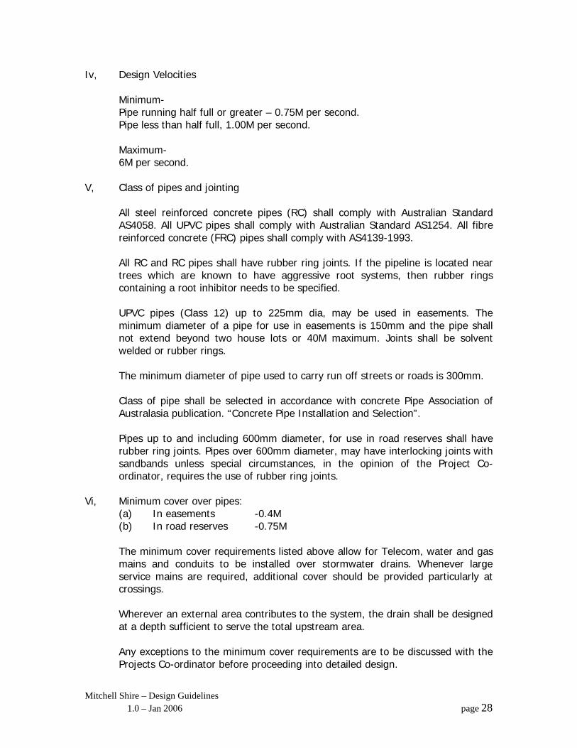
Iv, Design Velocities Minimum- Pipe running half full or greater – 0.75M per second. Pipe less than half full, 1.00M per second. Maximum- 6M per second. V, Class of pipes and jointing
All steel reinforced concrete pipes (RC) shall comply with Australian Standard AS4058. All UPVC pipes shall comply with Australian Standard AS1254. All fibre reinforced concrete (FRC) pipes shall comply with AS4139-1993. All RC and RC pipes shall have rubber ring joints. If the pipeline is located near trees which are known to have aggressive root systems, then rubber rings containing a root inhibitor needs to be specified. UPVC pipes (Class 12) up to 225mm dia, may be used in easements. The minimum diameter of a pipe for use in easements is 150mm and the pipe shall not extend beyond two house lots or 40M maximum. Joints shall be solvent welded or rubber rings. The minimum diameter of pipe used to carry run off streets or roads is 300mm. Class of pipe shall be selected in accordance with concrete Pipe Association of Australasia publication. “Concrete Pipe Installation and Selection”. Pipes up to and including 600mm diameter, for use in road reserves shall have rubber ring joints. Pipes over 600mm diameter, may have interlocking joints with sandbands unless special circumstances, in the opinion of the Project Co-ordinator, requires the use of rubber ring joints.
Vi, Minimum cover over pipes: (a) In easements -0.4M (b) In road reserves -0.75M
The minimum cover requirements listed above allow for Telecom, water and gas mains and conduits to be installed over stormwater drains. Whenever large service mains are required, additional cover should be provided particularly at crossings. Wherever an external area contributes to the system, the drain shall be designed at a depth sufficient to serve the total upstream area. Any exceptions to the minimum cover requirements are to be discussed with the Projects Co-ordinator before proceeding into detailed design.
Mitchell Shire – Design Guidelines 1.0 – Jan 2006 page 28
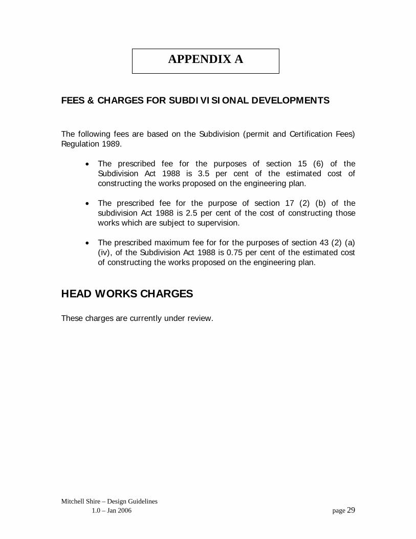
APPENDIX A
FEES & CHARGES FOR SUBDIVISIONAL DEVELOPMENTS The following fees are based on the Subdivision (permit and Certification Fees) Regulation 1989.
• The prescribed fee for the purposes of section 15 (6) of the Subdivision Act 1988 is 3.5 per cent of the estimated cost of constructing the works proposed on the engineering plan.
• The prescribed fee for the purpose of section 17 (2) (b) of the
subdivision Act 1988 is 2.5 per cent of the cost of constructing those works which are subject to supervision.
• The prescribed maximum fee for for the purposes of section 43 (2) (a)
(iv), of the Subdivision Act 1988 is 0.75 per cent of the estimated cost of constructing the works proposed on the engineering plan.
HEAD WORKS CHARGES These charges are currently under review.
Mitchell Shire – Design Guidelines 1.0 – Jan 2006 page 29