Statistical Leakage and Timing Optimization for Submicron Process Variation
CES TRANSACTIONS ON ELECTRICAL MACHINES AND SYSTEMS, VOL. 5, NO. 1, MARCH 2021 21
Abstract—A novel mechanical variable-leakage-flux interior
permanent magnet machine (MVLF-IPMM) is proposed for electric vehicles (EVs) in this paper, which employs a mechanical flux-regulating device and auxiliary rotatable magnetic poles. The magnetic poles acting as the flux adjustors can be rotated by the additional device to vary the leakage flux in magnetic circuit and realize the adjustment of the PM flux linkage. Due to the flux-regulating effect, the flux distribution in this machine is complex and changeable. Therefore, the working principle is illustrated in detail. To obtain the perfect coordination between the dominant magnetic poles and auxiliary magnetic poles, a multi-objective optimization method is presented based on the parameter sensitivity analysis combining with the Coefficient of Prognosis (CoP). Then, some design parameters with strong sensitive are selected by the sensitivity analysis and the initial model of the proposed motor is optimized by utilizing the multi-objective genetic algorithm (MOGA). According to the result of the optimization, the machine performances of the initial and the optimal design under the different flux states are compared and analyzed to verify the validity of the new variable-flux motor and the optimization method.
Index Terms—Finite element analysis (FEA), flux regulation, Interior permanent magnet machine, multi-objective optimization, sensitivity analysis.
I. INTRODUCTION
ARE-EARTH permanent magnet (PM) machines are employed extensively in electric vehicle (EV) applications
owing to the distinctive merits of high torque density and high efficiency [1]-[4]. Although rare-earth PM material exhibits high remanence of the PM, its air-gap magnetic field is difficult to be regulated, which results in the limited constant power
Manuscript received October 13, 2020; revised February 01, 2021; accepted February 26, 2021. date of publication March 25, 2021; date of current version March 18, 2021.
This work was supported in part by the National Natural Science Foundation of China under grant no. 51767009, in part by the Plan Project of Jiangxi Province of P.R. China under grant no. GJJ160598 and 20181BAB206035, and in part by the Program of Qingjiang Excellent Young Talents, Jiangxi University of Science and Technology (JXUST).(Corresponding Author: Liu, Xiping)
Tongze Sun, Xiping Liu, Yongling Zou, Chaozhi Huang and Jianwei Liang are with School of Electrical Engineering and Automation, Jiangxi University of Science and technology, Ganzhou 34100, China ([email protected])
Digital Object Identifier 10.30941/CESTEMS.2021.00004
speed range (CPSR). To satisfy the requirement of a wide CPSR for the driving system in electric vehicle applications, variable flux PM machines (VFPMMs) are proposed to overcome the above drawback, including hybrid excitation machines (HEMs), hybrid magnet memory machines (HMMMs), and mechanical-variable-flux PM machines (MVF-PMMs). For the HEMs [5]-[7], the magnetic field is regulated by either auxiliary excitation winding or armature winding change. However, the motors suffer from high copper loss and relatively less power density. In order to avoid the continuous copper loss, the HMMMs [8]-[10] are proposed with low coercive force magnets, which can realize flux regulation by different magnetization states. And yet, a complicated integration control system is required to limit further application. In addition, the emerging of MVF-PMMs [11]-[16] can solve the above issues. The machines utilize all kinds of mechanical means to achieve air-gap flux adjustment.
Generally, such machine adopting the variable flux design techniques often suffers from the new problem of relatively complex structures. Besides, to meet the requirements of high-performance drive motors for modern EVs, the optimization design has been investigated in many works [17]. In [18], a V-shaped IPM motor is optimized with a new multilevel optimization strategy, which is based on Pearson correlation coefficient analysis and cross-factor variance analysis. In [19], to improve flux modulation and flux regulation capability, a new segmented PM consequent pole hybrid excited machine is proposed for the applications of EVs. Furthermore, the geometric optimization is employed for studying impacts of design parameters on key performance indicators. In [20], a hybrid-magnetic-circuit memory machine is presented with series and parallel hybrid magnet structures. Due to the complex structure of PMs, the design variables are globally optimized by a genetic algorithm (GA). It is obvious that the comprehensive optimization has become an indispensable step in the design progress of machines.
Therefore, this paper presents a mechanical variable-leakage-flux interior permanent magnet motor (MVLF-IPMM) with auxiliary rotatable magnetic poles and a self-activating device, which can adjust flux effectively and conveniently without field current and complicated rotor
Design and Optimization of a Mechanical Variable-Leakage-Flux Interior Permanent Magnet Machine with Auxiliary Rotatable
Magnetic Poles
Tongze Sun, Xiping Liu, Yongling Zou, Chaozhi Huang, and Jianwei Liang
R
22 CES TRANSACTIONS ON ELECTRICAL MACHINES AND SYSTEMS, VOL. 5, NO. 1, MARCH 2021
structure. Double-layered PMs embedded in the rotor can improve output torque and flux-weakening capability. Generally, a permanent magnet motor with the high PM flux linkage can obtain the large output torque, whereas it also results in the high cogging torque and ripple torque. Hence, the different design parameters of the PMs have a prominent influence on the performance of the motor. It is difficult for the proposed machine to obtain the desired characteristic. The current literature about MVF-PM motor has focused mainly on performance analysis rather than the design optimization. For this new type of machine, the feasible design and optimization are still a concerning problem.
To effectively meet the requirements in automotive industrial applications, multiple objectives such as output torque, cogging torque and flux-regulating capability need to be considered during the design and optimization process of the proposed machine. Consequently, a multi-objective optimization method is presented by using the multi-objective genetic algorithm (MOGA) in this paper, where the design parameters are divided into two levels based on a sensitivity analysis strategy combining with the Coefficient of Prognosis (CoP). In section II, the topology and working principle of the MVLF-IPMM are introduced, respectively. In section III, an initial model of the MVLF-IPM machine is designed for the requirement of the flux-regulating ability. Then, the multi-objective optimization is performed to obtain the optimal design. Finally, in order to verify the effectiveness of the design model and optimization method, the electromagnetic characteristics between the initial and the optimal machines are investigated and compared in the different flux states.
II. STRUCTURE AND OPERATING PRINCIPLE
A. Machine Structure
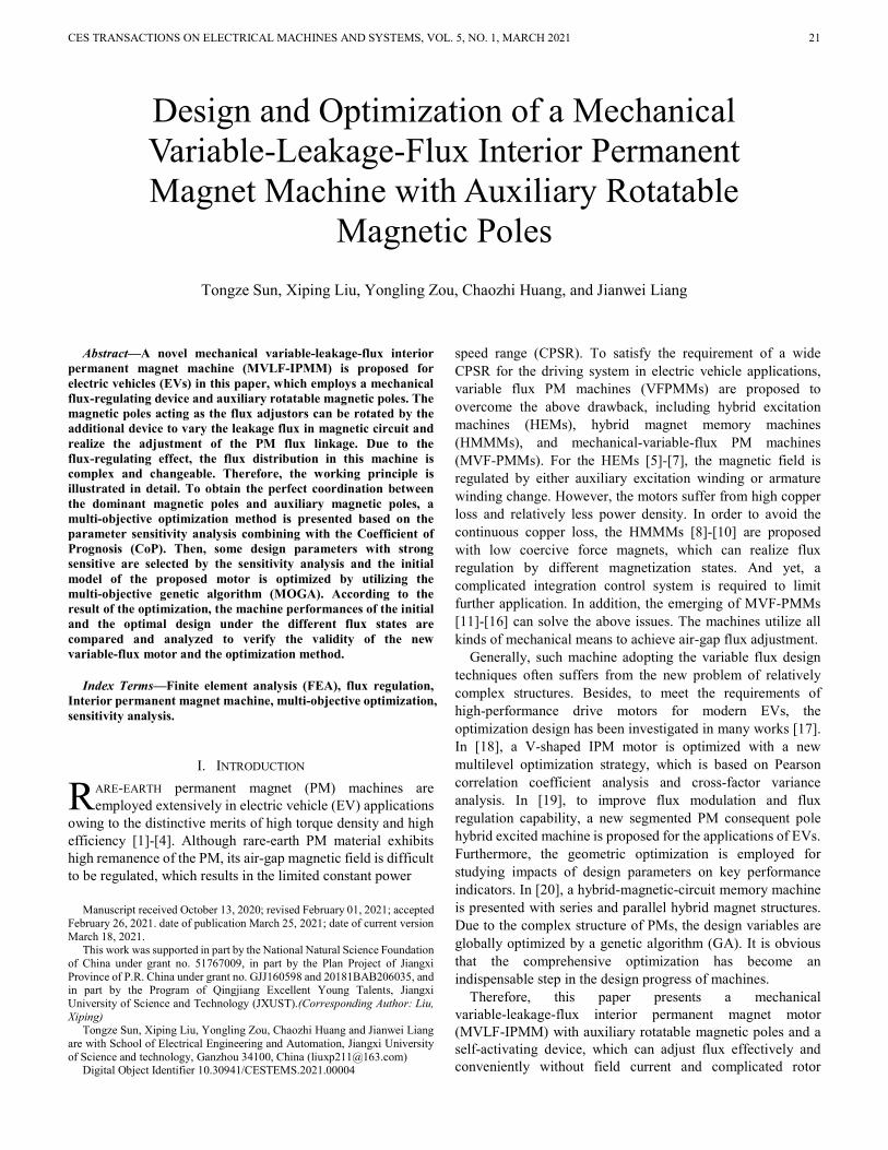
The cross-section view of the MVLF-IPM motor is illustrated in Fig. 1. The machine is mainly characterized by rotatable cylindrical magnetic poles for improved flux- weakening capability. A 48/8 slot-pole combination and three-phase distributed armature windings are adopted. Each rotor pole is embedded with one square permanent magnet (SPM) and two cylindrical permanent magnets (CPMs), in which the CPMs can be rotated by utilizing a mechanical device. Besides, the magnetic barriers are applied to achieve effective flux regulation.
Furthermore, a mechanical flux-regulating device is employed and placed at both sides of the rotors, as shown in Fig. 2. The device is configured with two endplates, including a master endplate and a slave endplate. The master endplate can be regarded as a set of assembly units. And each unit is made of a sliding block, a spring, two gears and two PM support rods. The sliding block acting as a flux adjuster is placed in its sliding chute. The spring is connected with a sliding block in the same unit to constrain the block. The gear takes the PM support rod as the rotating shaft, and each rod penetrates through the corresponding CPM, which is inserted into gear and slave endplate. Moreover, all rotatable parts in mechanical device are embedded with bearings to relieve the resistance of friction force. Therefore, with the change of speed, the sliding blocks
can radially move up and down, which can realize the clockwise and counter-clockwise autorotation of the gears and CPMs.
Fig. 1. Topology of the MVF-IPM machine.
Fig. 2. Structure of the flux-regulating device.
(a) (b)
Fig. 3. No-load magnetic circuit of the MVLF-IPMM under different MDs. (a) α=0°. (b) α=90°.
(a) (b)
Fig. 4. No-load field distributions under different MDs. (a) α=0°. (b) α=90°.
B. Operation Principle
The operation principle of the proposed machine follows the “mechanical-variable-flux theory” [21], which is indicated in Fig. 3. The SPMs serve as the dominant contributor for air-gap flux density, whereas the CPMs act as the flux adjustor due to their changeable magnetization directions (MDs). The CPMs are rotated by a certain angle depending on the speed and the mechanical device, which results in the change of the MDs of

SUN et al. : DESIGN AND OPTIMIZATION OF A MECHANICAL VARIABLE-LEAKAGE-FLUX INTERIOR PERMANENT MAGNET MACHINE WITH AUXILIARY ROTATABLE MAGNETIC POLES
23
CPMs. The angle between the d-axis and the MD is defined as α (i.e., the rotational angle of the CPM). The “maximum flux” and “minimum flux” states refer to “α=0° and α=90°,” respectively.
In constant torque range, the CPMs are maintained in the initial state shown in Fig. 3(a). The air-gap flux density can be kept the maximum value. Therefore, the motor can obtain a good performance of the output torque. For the high-speed region, with the increase of the speed, the right CPM and left CPM in the same rotor pole will be pushed to rotate clockwise and counterclockwise, respectively. As shown in Fig. 3(b), the CPMs rotated 90° are in the terminational state. It can be found that the displacement of the sliding blocks is transformed into the rotation of the CPMs. The leakage flux increases owing to the influence of magnetic barriers, which results in a significant reduction in the air-gap flux density. In this case, the proposed machine reaches the minimum flux state. Hence, it can spontaneously produce a flux-weakening effect. Besides, the PM flux linkage can be adjusted by the change of the MD, as illustrated by the corresponding open-circuit field distributions at different flux states plotted in Fig. 4.
Therefore, the leakage flux linkage Ψl of the MVLF-IPM machine, which is closely related to α, can be expressed as:
( ) 0 90l lN , (1)
Where N is the number of turns, Φσα is the leakage magnetic flux under different angles α. A coefficient k is defined as the ratio of leakage flux linkage to total magnetic flux linkage Ψpm provided by permanent magnets.
( )
(0,1)l
pm
k k
, (2)
It can be found from (2) that the coefficient k is relative with α. According to (2), the effective magnetic flux linkage Ψf is presented as: (1 )f pm l pmk (3)
Combining (3), the maximum angular speed of the proposed motor, by neglecting phase resistance, can be thereby written as follows:
limmax
lim
=((1 ) )pm d
U
p k L I
(4)
Where Ulim and Ilim are the limiting voltage and current, p and Ld are the rotor pole pairs and the d-axis inductance, respectively. Therefore, with the increase of the coefficient k, a wide constant power speed range can be obtained for the MVLF-IPM machine.
III. MACHINE OPTIMIZATION
To reduce the simulation time of optimization process and obtain the key design variables, this paper proposes the multi-objective optimization method based on two-level sensitivity analysis for the MVLF-IPMM. The detailed multi-objective optimization flowchart is described in Fig. 5, which includes several steps as follows:
Step 1: Initial design of the MVLF-IPM machine. According to the design theory of the IPM motors, the initial dimensions of
the proposed machine are obtained. The flux-regulating capability is enhanced through optimization of the magnetic barrier, and the design variables and the corresponding constraints are also selected to establish the parametric model. With the requirements of EV application, the optimization objectives are determined.
Step 2: Parameters sensitivity analysis. The sensitivity study combined with the CoP is adopted to calculate the correlation of design variables. Then, the design variables with different values of sensitivity are divided into two layers: weak-sensitivity and strong-sensitivity.
Step 3: Multi-objective optimization. Based on the above results, the strong-sensitivity design variables are selected to be as the input parameters of optimization. The MOGA optimization method is carried out to obtain the final values of the design variable.
Step 4: Performance analysis. In this step, the electromagnetic performance comparison before and after optimization is analyzed to verify the proposed machine and the optimization process.
Fig. 5. Flowchart of the proposed multi-objective optimal design method.
Fig. 6. Parametric model of the MVLF-IPM machine.
A. Initial Design
Different from the conventional IPM machines [22], the magnetic flux linkages λd and λq of the MVLF-IPMM in the d-q reference in the dynamic state are expressed by (5), and the

24 CES TRANSACTIONS ON ELECTRICAL MACHINES AND SYSTEMS, VOL. 5, NO. 1, MARCH 2021
electromagnetic torque Tm is represented by (6)
, ,
, ,
d d d q
q q d q
i i
i i
(5)
( , , ) ( , , )m d d q q q d q dT p i i i i i i (6)
Where id, iq are the d-axis and q-axis armature currents at dynamic state. The electromagnetic parameters of the proposed machine are affected by the rotational angle α. In order to better evaluate the flux regulation capability, the ratio of PM flux linkages under the maximum flux and minimum flux states is represented as follows
( 0 )
=( 90 )
f
f
(7)
Where γ is the flux-regulating ratio, ψf (α=0°) and ψf (α=90°) are the effective flux linkages of the maximum flux and minimum flux states, respectively.
TABLE I RANGE OF DESIGN VARIABLES
Design variables Unit Constraint ranges
SPM arc width αp1 degree [20.25, 27.5] CPM arc width αp2 degree [16.65, 22.5] Angle of SPM flux barrier βb1 degree [145, 154] Angle of CPM flux barrier βb2 degree [145, 160] Radius of CPM Rcpm mm [5, 6] SPM thickness ωspm mm [2.6, 3.6] Magnetic barrier thickness ωb mm [2.8, 3.8] Slot opening width Bs0 mm [1.8, 2.3] Slot width Bs1 mm [4, 6] Tooth width Bs2 mm [6. 10] Slot height Hs0 mm [29, 33]
TABLE II BASIC DESIGN PARAMETERS OF THE MVLF-IPMM
Items Values
Number of slots/poles 48/8 Rated output power 3 kW Rated speed 1500 rpm Rated phase voltage 58 V Stack length 40mm Turns per coil 9 Air gap 0.75mm NdFeB (20 °C) Br=1.21, Hc=-899kA/m
Fig. 7. CoP of the design variable to the three optimal goals.
According to the operation principle of the MVLF-IPMM, it can be noted that the magnetic barrier shows a significant influence on the flux-regulating ratio. Therefore, the shape, length and width of the magnetic barrier are optimized to satisfy the requirements of the flux adjustment. In addition, the
parametric model of the proposed machine is shown in Fig. 6, and some design parameters are chosen as optimization variables. The selected variables and corresponding variation ranges are listed in Table I. Considering the requirements of potential applications in VFPM machine, the output torque, torque ripple and cogging torque are selected as the optimization objectives. The basic design specifications of the MVLF-IPMM are given in Table II.
Fig. 8. Optimization results of the three optimization objectives.
B. Sensitivity Analysis
Sensitivity analysis technique based on CoP is used to identify the correlation between the design parameters and objectives [23]. The CoP of a single variable CoP(xi) is defined as follows
( ) (1 ) ( )P
MOPEi T i
T
SSCoP x S x
SS (8)
Where SSP E is the sum of squared prediction errors; SST is
equivalent to the total variation; xi (i=1,2,3…11) are the design variables, as given in Table I; SMOP
T(xi) is the sensitivity index considering total effects. Thus, the parameter sensitivity analysis is performed, while the CoP of each chosen design variable on the optimization objectives also is calculated by (8), as shown in Fig. 7.
According to the definition of the CoP, a large value of CoP(xi) indicates a remarkable influence on the optimization objectives. It can be seen from Fig. 8 that each design variable presents different sensitivities to optimization goals. The SPM arc width αp1, the SPM thickness ωspm and the magnetic barrier thickness ωb have strong sensitivity to the three output parameters, while the radius of CPM and the slot height have so little sensitivity to cogging torque. Hence, to determine the key input parameters, the design variables are divided into two levels based on the results of sensitivity analysis:
Level 1: Weak-sensitivity CoP(xi) < 10% Level 2: Strong-sensitivity CoP(xi) ≥ 10% Combining Fig. 7, the five key variables are included in level
2 and selected for multi-objective optimization.
C. Multi-Objective Optimization
As mentioned, the three optimization objectives and the five design variables are determined by the step 1 and 2 in the flowchart. To reduce the conflict of multiple goals, the trade-off objective function of the MVLF-IPMM is presented as follows:
min 1 2 3
( ) ( )( )
( )rip i cog iout
iout i rip cog
T x T xTf x
T x T T
(9)
SUN et al. : DESIGN AND OPTIMIZATION OF A MECHANICAL VARIABLE-LEAKAGE-FLUX INTERIOR PERMANENT MAGNET MACHINE WITH AUXILIARY ROTATABLE MAGNETIC POLES
25
The boundary constrains of the motor are
17
35%
0.5
out
rip
cog
T Nm
T
T Nm
(10)
Where T* out, T
* rip and T*
cog are the initial values of out torque, torque ripple and cogging torque; xi (i=1, 2, … ,5.) refer to the design variable αp1, ωspm, Rcpm, ωb, Bs0; ω1, ω2 and ω3 are the three weight coefficients which satisfy the equation ω1+ω2 +ω3 =1 and are assigned to be 0.4, 0.3 and 0.3, separately. Then, the multi-objective genetic algorithm method is adopted in this step, which is a variant of the popular non-dominated sorted genetic algorithm-Ⅱ based on controlled elitism concepts. Moreover, according to (9), the multi-objective function is set to realize a comprehensive consideration for the three optimization objectives. The results of the multi-objective optimization are shown in Fig. 8, where the optimal point (i.e., the red square point) can be obtained efficiently based on the optimization model. The final values of the design variables and objectives are determined and listed in Table Ⅲ.
TABLE Ⅲ OPTIMIZATION RESULTS
Design variables/Objectives Initial values Optimal values
αp1 (degree) 26.68 23.98 Rcpm (mm) 5.95 5.37 ωspm (mm) 3.33 2.74 ωb (mm) 2.53 3.79 Bs0 (mm) 1.80 1.93 γ 2.0 5.5 Tout (Nm) 16.8 19.2 Trip (%) 41.3 30.6 Tcog (Nm) 1.66 0.067 f(xi)min 0.83 0.45
IV. PERFORMANCE COMPARISON
To confirm the validity of the MVLF-IPM machine and the corresponding optimization method, the electromagnetic characteristics of the proposed machine between initial and optimal designs under the different MDs are compared by finite-element analysis. For the most essential feature of the proposed MVF-IPMM, the flux-regulating capability is firstly investigated. Moreover, since the presented motor is designed with multi-layer PMs, the structural strength of rotor will be a great challenge for this motor, especially during high-speed operation. The stress analysis is also performed in this section.
A. Flux-Regulating Capability
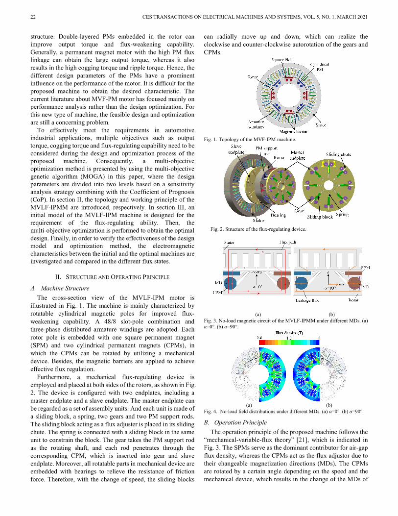
The effective PM flux linkage waveforms of the initial and optimal MVLF-IPMMs under the different MDs are simulated and shown in Fig. 9. It can be found that the peak value of optimal flux linkage in the maximum flux state reaches nearly 0.11Wb, which is higher than the initial design. Besides, the usage of PMs is decreased by 22.6%, which indicates a better PM utilization is obtained by the optimization design. Compared Fig. 9 (a) with (b), it is obvious that the peak value of PM flux linkage decreases significantly for the initial motor and the optimal motor, when the CPMs are rotated from 0° to 90°. According to (7), the flux-regulating ratios of the initial and optimal machines can be calculated, which are 2.0 and 5.5,
respectively. Moreover, the average flux linkages as functions of the rotational angle α are plotted in Fig. 10. The curve of the optimal design is sharper than the initial design. It should be noted that the optimal machine exhibits a more excellent flux regulation performance due to the efficient reduction of the effective PM flux linkage.
(a)
(b)
Fig. 9. Comparison of the effective PM flux linkages waveforms under different α. (a) α=0°. (b) α=90°.
Fig. 10. Average effective flux linkages under different α.
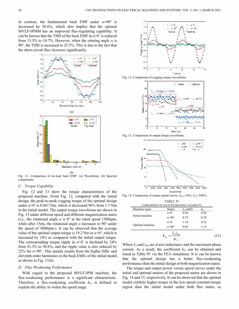
B. No-load Back EMF
The no-load back EMF waveforms and spectral components under the initial and optimal topologies are investigated and compared at the rated speed 1500 rpm, as shown in Fig. 11. As can be seen in Fig. 11(a), a more sinusoidal back EMF waveforms in α=0° can be obtained after optimization, which means the proposed motor can realize lower copper loss and vibration. Besides, from Fig. 11(b), the fundamental back EMF under α=0° is increased from 59.5V to 68.3V by optimization.
26 CES TRANSACTIONS ON ELECTRICAL MACHINES AND SYSTEMS, VOL. 5, NO. 1, MARCH 2021
In contrast, the fundamental back EMF under α=90° is decreased by 58.6%, which also implies that the optimal MVLF-IPMM has an improved flux-regulating capability. It can be known that the THD of the back EMF in α=0° is reduced from 13.5% to 10.7%. However, when the rotating angle α is 90°, the THD is increased to 25.5%. This is due to the fact that the short-circuit flux increases significantly.
(a)
(b)
Fig. 11. Comparison of no-load back EMF. (a) Waveforms. (b) Spectral components.
C. Torque Capability
Fig. 12 and 13 show the torque characteristics of the proposed machine. From Fig. 12, compared with the initial design, the peak-to-peak cogging torque of the optimal design under α=0° is 0.067 Nm, which is decreased 96% from 1.7 Nm in the initial model. The output torque waveforms are shown in Fig. 13 under different speed and different magnetization states (i.e., the rotational angle α is 0° at the rated speed 1500rpm, while after 15ms, the rotational angle α increases to 90° under the speed of 3000rpm.). It can be observed that the average value of the optimal output torque is 19.2 Nm in α=0°, which is increased by 14% as compared with the initial output torque. The corresponding torque ripple in α=0° is declined by 24% from 41.3% to 30.6%, and the ripple value is also reduced by 22% for α=90°. This mainly results from the higher fifth- and eleventh-order harmonics in the back EMFs of the initial model, as shown in Fig. 11(b).
D. Flux-Weakening Performance
With regard to the proposed MVLF-IPM machine, the flux-weakening performance is a significant characteristic. Therefore, a flux-weakening coefficient kfw is defined to explain the ability to widen the speed range.
Fig. 12. Comparison of cogging torque waveforms.
Fig. 13. Comparison of output torque waveforms.
Fig. 14. Comparison of torque-speed curves. (Irms=19A, Udc=100V).
TABLE IV COMPARISON OF FLUX-WEAKENING CAPABILITY
Machine types States Ld (mH) kfw
Initial machine α=0° 0.94 0.28
α=90° 0.72 0.39
Optimal machine α=0° 1.18 0.32
α=90° 0.85 1.14
limdfw
f
L ik
(11)
Where Ld and ilim are d-axis inductance and the maximum phase current. As a result, the coefficient kfw can be obtained and listed in Table IV via the FEA simulation. It is can be known that the optimal design has a better flux-weakening performance than the initial design at both magnetization states.
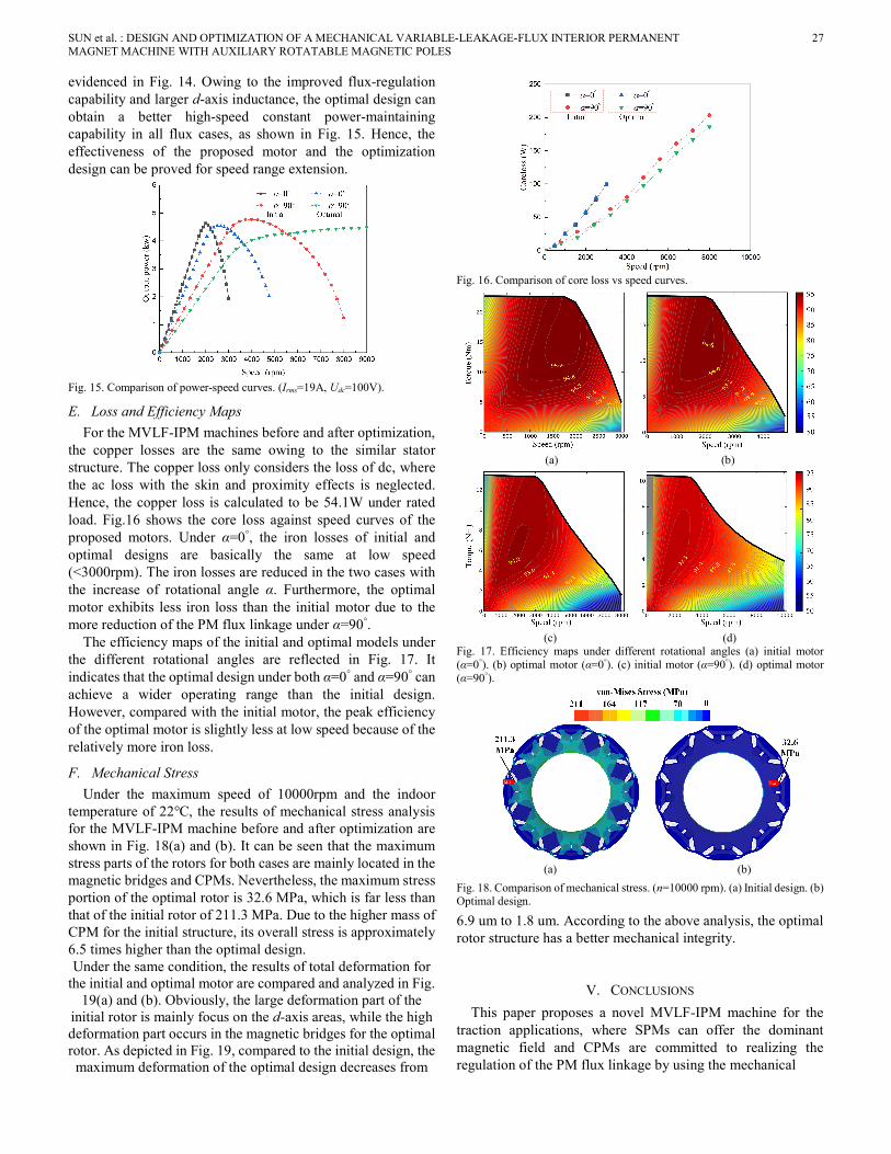
The torque and output power versus speed curves under the initial and optimal motors of the proposed motor are shown in Fig. 14 and 15, respectively. It can be observed that the optimal model exhibits higher torque in the low-speed constant-torque region than the initial model under both flux states, as
SUN et al. : DESIGN AND OPTIMIZATION OF A MECHANICAL VARIABLE-LEAKAGE-FLUX INTERIOR PERMANENT MAGNET MACHINE WITH AUXILIARY ROTATABLE MAGNETIC POLES
27
evidenced in Fig. 14. Owing to the improved flux-regulation capability and larger d-axis inductance, the optimal design can obtain a better high-speed constant power-maintaining capability in all flux cases, as shown in Fig. 15. Hence, the effectiveness of the proposed motor and the optimization design can be proved for speed range extension.
Fig. 15. Comparison of power-speed curves. (Irms=19A, Udc=100V).
E. Loss and Efficiency Maps
For the MVLF-IPM machines before and after optimization, the copper losses are the same owing to the similar stator structure. The copper loss only considers the loss of dc, where the ac loss with the skin and proximity effects is neglected. Hence, the copper loss is calculated to be 54.1W under rated load. Fig.16 shows the core loss against speed curves of the proposed motors. Under α=0°, the iron losses of initial and optimal designs are basically the same at low speed (<3000rpm). The iron losses are reduced in the two cases with the increase of rotational angle α. Furthermore, the optimal motor exhibits less iron loss than the initial motor due to the more reduction of the PM flux linkage under α=90°.
The efficiency maps of the initial and optimal models under the different rotational angles are reflected in Fig. 17. It indicates that the optimal design under both α=0° and α=90° can achieve a wider operating range than the initial design. However, compared with the initial motor, the peak efficiency of the optimal motor is slightly less at low speed because of the relatively more iron loss.
F. Mechanical Stress
Under the maximum speed of 10000rpm and the indoor temperature of 22℃, the results of mechanical stress analysis for the MVLF-IPM machine before and after optimization are shown in Fig. 18(a) and (b). It can be seen that the maximum stress parts of the rotors for both cases are mainly located in the magnetic bridges and CPMs. Nevertheless, the maximum stress portion of the optimal rotor is 32.6 MPa, which is far less than that of the initial rotor of 211.3 MPa. Due to the higher mass of CPM for the initial structure, its overall stress is approximately 6.5 times higher than the optimal design. Under the same condition, the results of total deformation for
the initial and optimal motor are compared and analyzed in Fig. 19(a) and (b). Obviously, the large deformation part of the
initial rotor is mainly focus on the d-axis areas, while the high deformation part occurs in the magnetic bridges for the optimal rotor. As depicted in Fig. 19, compared to the initial design, the
maximum deformation of the optimal design decreases from
Fig. 16. Comparison of core loss vs speed curves.
(a) (b)
(c) (d)
Fig. 17. Efficiency maps under different rotational angles (a) initial motor (α=0°). (b) optimal motor (α=0°). (c) initial motor (α=90°). (d) optimal motor (α=90°).
(a) (b)
Fig. 18. Comparison of mechanical stress. (n=10000 rpm). (a) Initial design. (b) Optimal design.
6.9 um to 1.8 um. According to the above analysis, the optimal rotor structure has a better mechanical integrity.
V. CONCLUSIONS
This paper proposes a novel MVLF-IPM machine for the traction applications, where SPMs can offer the dominant magnetic field and CPMs are committed to realizing the regulation of the PM flux linkage by using the mechanical

28 CES TRANSACTIONS ON ELECTRICAL MACHINES AND SYSTEMS, VOL. 5, NO. 1, MARCH 2021
(a) (b)
Fig. 19. Comparison of total deformation. (n=10000 rpm). (a) Initial design. (b) Optimal design.
device. Therefore, the double-layered PM structure has a significant effect on the machine performances. To improve the overall performances of the proposed motor, a multi-objective optimal design method is presented in this paper. Based on the CoP, five design variables with high sensitivity are selected as input parameters. Then, three objectives, i.e., output torque, torque ripple and cogging torque, are optimized by using the MOGA. After optimization, the electromagnetic performances and mechanical stress between the initial and the optimal design models are compared and analyzed. It can be found that the torque and flux-regulating capabilities are improved for the optimal MVLF-IPMM, which also exhibits the validity of the optimization method.
REFERENCES [1] Z. Q. Zhu, W. Q. Chu, and Y. Guan, "Quantitative comparison of
electromagnetic performance of electrical machines for hevs/evs," CES Transactions on Electrical Machines and Systems, vol. 1, no. 1, pp. 37-47, 2017.
[2] Z. Yang, F. Shang, I. P. Brown, and M. Krishnamurthy, "Comparative study of interior permanent magnet, induction, and switched reluctance motor drives for ev and hev applications," IEEE Transactions on Transportation Electrification, vol. 1, no. 3, pp. 245-254, 2015.
[3] X. Liu, H. Chen, J. Zhao, and A. Belahcen, "Research on the performances and parameters of interior pmsm used for electric vehicles," IEEE Transactions on Industrial Electronics, vol. 63, no. 6, pp. 3533-3545, 2016.
[4] D. Yu, X. Y. Huang, Y. T. Fang, and J. Zhang, "Design and comparison of interior permanent magnet synchronous traction motors for high speed railway applications," in 2017 IEEE Workshop on Electrical Machines Design, Control and Diagnosis (WEMDCD), April 2017, pp. 20-21.
[5] L. Cao, K. T. Chau, C. H. T. Lee, and W. Lam, "Design and analysis of a new parallel-hybrid-excited machine with harmonic-shift structure," IEEE Transactions on Industrial Electronics, vol. 67, no. 3, pp. 1759-1770, 2020.
[6] X. Sun and Z. Q. Zhu, "Investigation of dc winding induced voltage in hybrid-excited switched-flux permanent magnet machine," IEEE Transactions on Industry Applications, vol. 56, no. 4, pp. 3594-3603, 2020.
[7] J. Li and K. Wang, "A parallel hybrid excited machine using consequent pole rotor and ac field winding," IEEE Transactions on Magnetics, vol. 55, no. 6, pp. 1-5, 2019.
[8] Y. Zheng, L. Wu, Y. Fang, X. Huang, and Q. Lu, "A hybrid interior permanent magnet variable flux memory machine using two-part rotor," IEEE Transactions on Magnetics, vol. 55, no. 7, pp. 1-8, 2019.
[9] H. Hua, Z. Q. Zhu, A. Pride, R. Deodhar, and T. Sasaki, "Comparative study on variable flux memory machines with parallel or series hybrid magnets," IEEE Transactions on Industry Applications, vol. 55, no. 2, pp. 1408-1419, 2019.
[10] H. Yang, Z. Q. Zhu, H. Lin, and S. Lyu, "Comparative study of hybrid pm memory machines having single- and dual-stator configurations," IEEE Transactions on Industrial Electronics, vol. 65, no. 11, pp. 9168-9178, 2018.
[11] Z. Q. Zhu, M. M. J. Al-Ani, X. Liu, and B. Lee, "A mechanical flux weakening method for switched flux permanent magnet machines," IEEE Transactions on Energy Conversion, vol. 30, no. 2, pp. 806-815, 2015.
[12] X. Liu, M. Wang, D. Chen, and Q. Xie, "A variable flux axial field permanent magnet synchronous machine with a novel mechanical device," IEEE Transactions on Magnetics, vol. 51, no. 11, pp. 1-4, 2015.
[13] A. Tessarolo, M. Mezzarobba, and R. Menis, "Modeling, analysis, and testing of a novel spoke-type interior permanent magnet motor with improved flux weakening capability," IEEE Transactions on Magnetics, vol. 51, no. 4, pp. 1-10, 2015.
[14] C. H. T. Lee, J. L. Kirtley, and M. Angle, "A partitioned-stator flux-switching permanent-magnet machine with mechanical flux adjusters for hybrid electric vehicles," IEEE Transactions on Magnetics, vol. 53, no. 11, pp. 1-7, 2017.
[15] T. Ishii, T. Nonaka, S. Oga, and M. Ohto, "Manufacturing and control of a variable magnetic flux motor prototype with a mechanical adjustment method," Electr. Eng. Jpn., vol. 199, no. 1, pp. 57-66, Apr 2017.
[16] W. Liu, H. Yang, and H. Lin, "Design and analysis of a novel mechanical-variable-flux stator consequent-pole machine," in Proc. 22nd Int. Conf. on Elect. Mach. Syst. (ICEMS), Aug. 2019, pp. 1-6.
[17] X. Sun, Z. Shi, Y. Cai, G. Lei, Y. Guo, and J. Zhu, "Driving-cycle-oriented design optimization of a permanent magnet hub motor drive system for a four-wheel-drive electric vehicle," IEEE Transactions on Transportation Electrification, vol. 6, no. 3, pp. 1115-1125, 2020.
[18] X. Sun, Z. Shi, G. Lei, Y. Guo, and J. Zhu, "Multi-objective design optimization of an ipmsm based on multilevel strategy," IEEE Transactions on Industrial Electronics, vol. 68, no. 1, pp. 139-148, 2021.
[19] W. Ullah, F. Khan, and M. Umair, "Design and optimization of segmented pm consequent pole hybrid excited flux switching machine for ev/hev application," CES Transactions on Electrical Machines and Systems, vol. 4, no. 3, pp. 206-214, 2020.
[20] H. Yang, S. Lyu, H. Lin, Z. Zhu, H. Zheng, and T. Wang, "A novel hybrid-magnetic-circuit variable flux memory machine," IEEE Transactions on Industrial Electronics, vol. 67, no. 7, pp. 5258-5268, 2020.
[21] X. Liu, T. Sun, Y. Zou, C. Huang, J. Liang, "Modelling and analysis of a novel mechanical-variable-flux IPM machine with rotatable magnetic poles," IET Electric Power Applications, vol. 14, no. 14, pp. 2171-2178, 2020.
[22] H. Kim, J. Jeong, M. Yoon, J. Moon, and J. Hong, "Simple size determination of permanent-magnet synchronous machines," IEEE Transactions on Industrial Electronics, vol. 64, no. 10, pp. 7972-7983, 2017.
[23] T. Most and J. Will, "Sensitivity analysis using the metamodel of optimal prognosis," Technical report, Dynardo: Weimar, Germany, 2011.
XIPING LIU received his B.S. degree from Hohai University, Nanjing, China, in 1999; his M.S. degree from the Jiangxi University of Science and Technology, Ganzhou, China, in 2004; and his Ph.D. degree in Electrical Engineering from Southeast University, Nanjing, China, in 2009. He is presently working as a Professor in the Department of Electrical Engineering and Automation,
Jiangxi University of Science and Technology. His current research interests include the analysis and design of permanent magnet synchronous machine, and wind power technology.

SUN et al. : DESIGN AND OPTIMIZATION OF A MECHANICAL VARIABLE-LEAKAGE-FLUX INTERIOR PERMANENT MAGNET MACHINE WITH AUXILIARY ROTATABLE MAGNETIC POLES
29
TONGZE SUN was born in China, in 1994. He received his B.S. degree in Electrical Engineering and Automation from Henan University of Engineering, Henan, China, in 2017. He is presently working toward his M.S. degree in Control Engineering at the Jiangxi University of Science and Technology, Ganzhou, China. His current
research interests include the design of permanent magnet motors, the flux-adjusting of variable flux PMSMs and their multi-objective optimization method.
YONGLING ZOU was born in China, in 1995. She is presently working towards her M.S. degree in interests include the Electrical Engineering at the Jiangxi University of Science and Technology, Ganzhou, China. Her current research design and analysis of PMSM, and the flux-adjusting of variable flux PMSMs.
CHAOZHI HUANG was born in China. He received his B.S. and M.S. degrees in the School of Electrical Engineering and Automation, Jiangxi University of Science and Technology, Ganzhou, China, in 2001 and 2004, respectively. He is presently working towards his Ph.D. degree in the College of Energy and Electrical Engineering, Hohai University, Jiangsu,
China. He is presently working as an Associate Professor at the Jiangxi University of Science and Technology. His current research interests include PMSMs and SRMs, and their drive and control, and power electronics applications.
JIANWEI LIANG was born in China. He received his B.S. degree from Jiangxi University of Science and Technology, Ganzhou, China; his M.S. degree from the Nanchang University, Nanchang, China. He is presently working as an Associate Professor at the Jiangxi University of Science and Technology. His current research interests include PMSMs, and their
drive and control.