Design and Implementation of an Efficient SCA Framework for ... · Design and Implementation of an...
94
Design and Implementation of an Efficient SCA Framework for Software-Defined Radios Carlos R. Aguayo Gonzalez Thesis submitted to the Faculty of the Virginia Polytechnic Institute and State University in partial fulfillment of the requirements for the degree of Master of Science in Electrical Engineering Annamalai Annamalai, Chair Jeffrey H. Reed, Chair William H. Tranter May 10, 2006 Blacksburg, Virginia Keywords: Wireless Communications, Software Radio, SCA Implementation Copyright 2006, Carlos R. Aguayo Gonzalez
Transcript of Design and Implementation of an Efficient SCA Framework for ... · Design and Implementation of an...

Design and Implementation of an Efficient SCA Framework for
Software-Defined Radios
Carlos R. Aguayo Gonzalez
Thesis submitted to the Faculty of the
Virginia Polytechnic Institute and State University
in partial fulfillment of the requirements for the degree of
Master of Science
in
Electrical Engineering
Annamalai Annamalai, Chair
Jeffrey H. Reed, Chair
William H. Tranter
May 10, 2006
Blacksburg, Virginia
Keywords: Wireless Communications, Software Radio, SCA Implementation
Copyright 2006, Carlos R. Aguayo Gonzalez
Design and Implementation of an Efficient SCA Framework for
Software-Defined Radios
Carlos R. Aguayo Gonzalez
ABSTRACT
Software Defined Radio (SDR) is a relatively new approach to develop wireless communi-
cation systems. SDR presents a framework for developing flexible, reconfigurable devices
intended to alleviate some of the issues arising from the evolution of wireless technology.
The Software Communications Architecture (SCA), developed by the Joint Tactical Radio
System program of the US Department of Defense, is an open architecture for implementing
SDR, relying on commercial technology, standard interfaces, and well-known design patterns.
Although the SCA is intended to provide easier, faster development of flexible applications
that are upgradeable and maintainable, the acceptance of the architecture has been limited
in part by traditional radio engineers’ lack of understanding modern software engineering
techniques. Because of the steep learning curve, some developers face frustration and serious
delays when first introduced to the SCA. This work presents a comprehensive tutorial which
introduces radio engineers to the SCA and the techniques used in it.
Another concern for accepting the SCA are the performance, size, cost, and power con-
suption difficulties faced in early implementations of the architecture. Traditionally, SCA
implementations have been developed for platforms based on General Purpose Processors.
This approach, while believed to be the easiest to implement, does not make the best out
of available processor technology. In order to provide a more efficient implementation of ra-
dios based on the SCA, we present the design and development of an SCA Core Framework
version 2.2 for a homogeneous TI C64 DSP platform. This framework is implemented by
leveraging the existing implementation of the Open-Source SCA Implementation::Embedded
(OSSIE) by porting it to the C64 platform. Two sample waveforms are developed and de-
ployed to demonstrate the functionality of the framework. Preliminary performance and
memory footprint profiling results are provided.

Para toda mi familia, quienes siempre me apoyaron y confiaron en mi.
iii

Acknowledgments
I would like to thank my advisor Dr. Annamalai Annamalai, for his support, assistance, and
patience during the development of this and all other projects. My great appreciation goes
to Dr. Jeffrey H. Reed, whose vision, guidance, and support made this project possible. I
would also like to thank Dr. William H. Tranter, for his support of this research. I want
to express my gratitude to all faculty, staff, and students at MPRG whose assistance and
friendship has made this work possible.
I would like to specifically thank the OSSIE Team: Max, Carl, Shereef, Philip, Tom, Jacob,
Tuan, and Joe, for sharing their fiendship and support and for making the development of
thousands of lines of code much easier. It would have been impossible to develop this project
without all your support.
A special acknowledgement is due to Lauren, for her support and encouragements and for
helping me understand the balance between work and life. Finally, I would like to thank my
family, for being there for me over the years. Their love, encouragement, and example have
forged the person I am now.
This work was supported by Texas Instruments, PrismTech, Mercury Computer, and by the
National Council of Science and Technology (CONACYT) of Mexico
iv

Contents
1 Introduction 1
1.1 Motivation . . . . . . . . . . . . . . . . . . . . . . . . . . . . . . . . . . . . . 1
1.2 Contributions . . . . . . . . . . . . . . . . . . . . . . . . . . . . . . . . . . . 4
1.3 Thesis Organization . . . . . . . . . . . . . . . . . . . . . . . . . . . . . . . . 4
2 Background 6
2.1 Software Defined Radios . . . . . . . . . . . . . . . . . . . . . . . . . . . . . 6
2.2 Related Work . . . . . . . . . . . . . . . . . . . . . . . . . . . . . . . . . . . 8
2.2.1 NASA’s Space Telecommunications Radio System . . . . . . . . . . . 8
2.2.2 GNU Radio . . . . . . . . . . . . . . . . . . . . . . . . . . . . . . . . 10
3 Introduction to the SCA 12
3.1 SCA Specifications . . . . . . . . . . . . . . . . . . . . . . . . . . . . . . . . 15
3.2 The Software Architecture . . . . . . . . . . . . . . . . . . . . . . . . . . . . 15
3.3 The SCA Operating Environment . . . . . . . . . . . . . . . . . . . . . . . . 16
3.3.1 Real-Time Operating System . . . . . . . . . . . . . . . . . . . . . . 17
v
3.3.2 Object Request Broker . . . . . . . . . . . . . . . . . . . . . . . . . . 18
3.4 The SCA Core Framework . . . . . . . . . . . . . . . . . . . . . . . . . . . . 21
3.4.1 Base Application Interfaces . . . . . . . . . . . . . . . . . . . . . . . 22
3.4.2 Framework Control Interfaces . . . . . . . . . . . . . . . . . . . . . . 25
3.4.3 Framework Services Interfaces . . . . . . . . . . . . . . . . . . . . . . 29
3.4.4 Domain Profile . . . . . . . . . . . . . . . . . . . . . . . . . . . . . . 29
3.5 SCA Waveforms . . . . . . . . . . . . . . . . . . . . . . . . . . . . . . . . . . 32
3.6 SCA Operational Sequence . . . . . . . . . . . . . . . . . . . . . . . . . . . . 33
3.7 The Open-Source SCA Implementation::Embedded OSSIE . . . . . . . . . . 35
3.8 The Hardware Abtraction Layer – Connectivity . . . . . . . . . . . . . . . . 36
4 Implementing the SCA Core Framework on a C64 Platform 38
4.1 OSSIE-TI System Architecture . . . . . . . . . . . . . . . . . . . . . . . . . 38
4.2 Software Architecture . . . . . . . . . . . . . . . . . . . . . . . . . . . . . . . 39
4.3 Platform . . . . . . . . . . . . . . . . . . . . . . . . . . . . . . . . . . . . . . 40
4.4 Real Time Implementation . . . . . . . . . . . . . . . . . . . . . . . . . . . . 41
4.5 Porting of OSSIE to the C64 Platform . . . . . . . . . . . . . . . . . . . . . 41
4.6 XML Parsing Strategy and implementation . . . . . . . . . . . . . . . . . . . 43
4.7 File System . . . . . . . . . . . . . . . . . . . . . . . . . . . . . . . . . . . . 46
4.8 Software Component Deployment . . . . . . . . . . . . . . . . . . . . . . . . 46
4.9 Sample Application . . . . . . . . . . . . . . . . . . . . . . . . . . . . . . . . 47
vi

5 Results 49
5.1 Application Deployment . . . . . . . . . . . . . . . . . . . . . . . . . . . . . 49
5.2 Profile and Benchmarking . . . . . . . . . . . . . . . . . . . . . . . . . . . . 53
5.2.1 Memory Footprint . . . . . . . . . . . . . . . . . . . . . . . . . . . . 53
5.2.2 Performance Profile . . . . . . . . . . . . . . . . . . . . . . . . . . . . 59
5.3 e*ORB Profiling . . . . . . . . . . . . . . . . . . . . . . . . . . . . . . . . . . 62
5.3.1 Impact on Data Rate Performance . . . . . . . . . . . . . . . . . . . 63
6 Conclusions 67
6.1 Future Work . . . . . . . . . . . . . . . . . . . . . . . . . . . . . . . . . . . . 68
A C64 Domain Profile Description 72
vii
List of Figures
2.1 Model of a Software Defined Radio . . . . . . . . . . . . . . . . . . . . . . . 7
3.1 SCA Software Structure . . . . . . . . . . . . . . . . . . . . . . . . . . . . . 17
3.2 Notional Relationship of OE and Applications to SCA AEP . . . . . . . . . 19
3.3 Communication Between CORBA Components . . . . . . . . . . . . . . . . 21
3.4 SCA CF IDL Relationships . . . . . . . . . . . . . . . . . . . . . . . . . . . 23
3.5 Resource Interface UML Model . . . . . . . . . . . . . . . . . . . . . . . . . 24
3.6 Device Interface Family UML Model . . . . . . . . . . . . . . . . . . . . . . 27
3.7 Application Factory Behavior Instantiation/Deployment . . . . . . . . . . . 28
3.8 XML Domain Profile Relationships . . . . . . . . . . . . . . . . . . . . . . . 31
3.9 Domain Manager Boot Up Sequence . . . . . . . . . . . . . . . . . . . . . . 33
3.10 Device Manager Boot Up Sequence . . . . . . . . . . . . . . . . . . . . . . . 34
3.11 Application Create Sequence . . . . . . . . . . . . . . . . . . . . . . . . . . . 34
4.1 Software Structure . . . . . . . . . . . . . . . . . . . . . . . . . . . . . . . . 39
4.2 SignalMaster Quad C6416 Block Diagram . . . . . . . . . . . . . . . . . . . 41
4.3 Processing Node Deployment Scheme . . . . . . . . . . . . . . . . . . . . . . 44
viii

4.4 Simplified Parsing Strategy . . . . . . . . . . . . . . . . . . . . . . . . . . . . 45
4.5 Sample BPSK Application Waveform . . . . . . . . . . . . . . . . . . . . . . 48
4.6 Sample QPSK Application Waveform . . . . . . . . . . . . . . . . . . . . . . 48
5.1 Demonstration Inital State and Waveform Selection . . . . . . . . . . . . . . 50
5.2 BPSK Waveform Operation Snapshot . . . . . . . . . . . . . . . . . . . . . . 51
5.3 QPSK Waveform Operation Snapshot . . . . . . . . . . . . . . . . . . . . . . 52
5.4 Memory Footprint Summary . . . . . . . . . . . . . . . . . . . . . . . . . . . 55
5.5 Core Framework Memory Footprint . . . . . . . . . . . . . . . . . . . . . . . 57
5.6 Parser Memory Footprint . . . . . . . . . . . . . . . . . . . . . . . . . . . . . 60
5.7 BPSK/QPSK Demo Application Memory Footprint . . . . . . . . . . . . . . 61
5.8 e*ORB Memory Footprint . . . . . . . . . . . . . . . . . . . . . . . . . . . . 61
5.9 e*ORB C++ for DSPs Marshalling Profile (CPU Clock Cycles) . . . . . . . 66
ix

List of Tables
4.1 Partial FileSystem Functionality . . . . . . . . . . . . . . . . . . . . . . . . . 46
5.1 Total Memory Allocation . . . . . . . . . . . . . . . . . . . . . . . . . . . . . 54
5.2 Major Components Contribution . . . . . . . . . . . . . . . . . . . . . . . . 55
5.3 Core Framework Memory Footprint Breakdown . . . . . . . . . . . . . . . . 57
5.4 Parsers Memory Footprint by class . . . . . . . . . . . . . . . . . . . . . . . 58
5.5 BPSK/QPSK Sample Application Memory Footprint by class . . . . . . . . 60
5.6 e*ORB Memory Footprint by Library . . . . . . . . . . . . . . . . . . . . . . 61
5.7 CF Tasks Performance Profile . . . . . . . . . . . . . . . . . . . . . . . . . . 62
5.8 e*ORB C++ for DSPs Marshalling Profile (CPU Clock Cycles) . . . . . . . 64
x
Chapter 1
Introduction
1.1 Motivation
Software Defined Radio (SDR) is a relatively new approach to develop wireless communi-
cation systems. SDR presents a framework for developing flexible, reconfigurable devices
intended to alleviate some of the issues arising from the evolution of wireless technology.
The main benefit of SDRs over programmable digital radios (e.g. current cell phones) is the
ability of SDRs to be reconfigured to satisfy user needs. Note, performing typical communi-
cation tasks, such as demodulation, decoding, filtering, or equalization, using digital signal
processing does not necessarily qualify the device as a Software Defined Radio.
The wireless industry has recognized and accepted the advantages of SDR. Due to its en-
hanced flexibility and quick development, a software-oriented implementation is the logical
option when developing wireless technology, provided that design and operational constraints
can be met. Communications engineers have been following this approach for a long time,
implementing in software every possible component in their designs (e.g. modern cell phones
and base stations).
The flexibility of a software-based approach to implement wireless systems has a big impact
1

Carlos R. Aguayo Gonzalez Chapter 1. Introduction 2
in the system architecture and the development process itself. Developers are faced with new
tradeoffs that need to be addressed in order to achieve the maximum performance in the
most efficient way (e.g. component reuse vs memory footprint, scalability vs performance).
However, addressing these tradeoffs requires the evaluation of characteristics that are hard
to quantify within the context of traditional wireless systems. In the SDR arena, it is not
only about performance, power, cost and size. Issues like code reuse, technology insertion,
platform scalability and flexibility have to be considered as well. Because of these issues
there is no general consensus on the best implementation approach for SDR, despite the
great interest in the technology,
There are innumerable different ways to implement SDR. Ideally, developers want to fol-
low an optimized development approach that allows enhanced reconfigurability, flexibility,
and easy maintenance, while increasing reuse of intellectual property and reducing time to
market. Following a component-based development approach to implement SDR holds the
promise of delivering such advantages. Recently, a component-based architecture has gener-
ated great interest in the wireless community. The Software Communications Architecture
(SCA)[1], developed by the Joint Tactical Radio System program of the US Department
of Defense, is an open architecture that relies on commercial technology, standard inter-
faces, and well-known design patterns to provide an operational environment to implement,
manage and operate SDR. Its main advantages are platform independence and enhanced
Intellectual Property (IP) reuse. These characteristics ultimately translate into easier, faster
development of flexible applications that are upgradeable and maintainable.
However, providing multiple benefits alone is not guaranty of acceptance. As with most open
standards, the success of the SCA depends on the establishment of a positive self-reinforcing
trend not only in the military but also in the commercial sector. This trend starts with a
large number of users adopting the architecture, leading to investment in tool development
which translates into faster and easier development. These improvements motivate more
users to addopt the architecture, and the self reinforcing trend is established.

Carlos R. Aguayo Gonzalez Chapter 1. Introduction 3
Unfortunatelly, there is a gap between the development tactics of traditional radio engineers
and the modern software engineering techniques required in SDR development. Cost efficient
development of SDR requires a robust architecture like the SCA along with a set of software
engineering skills that traditional radio developers usually lack. Because of this gap, some
developers face frustration and serious delays when first introduced to the SCA. This frus-
tration has led some communication engineers to believe that Software Defined Radio makes
the implementation of wireless technology more complicated. It is necessary an educational
document which introduces radio engineers to the concepts and techniques used in the SCA,
and similar architectures, to catalize the development of SDR technology.
Besides the steep learning curve, communications enginners have performance concerns about
the SCA. These concerns (e.g. increased overhead, latency, and memory footprint) further
limit the widespread use of the SCA, preventing the establishment of a self-reinforced positive
trend. Early implementations of the SCA have struggled to meet performance, cost, and
schedule requirements. Arguably, some of the inefficiencies in the SCA have their origin
in the assumption of a General Purpose Processor (GPP)-based platform to perform all
signal processing. Even though it is assumed that GPPs are the easiest devices to program
providing the highest reconfigurability and flexibility, they don’t score so well in the cost,
size, and power efficiency arenas. In order to overcome this limitation, it is necessary to
make better use of specialized hardware optimized for signal processing.
Digital Signal ProcessorS (DSP) are a special kind of microprocessors designed specifically
for digital signal processing and are widely used in real-time applications. Thanks to the
evolution of software development tools, it is possible to implement an SCA framework
using only DSPs. By implementing the SCA on such platform, the flexibility and reusability
delivered by the SCA are complemented with the cost and power efficiency that characterize
DSPs. This implementation will provide insight into the compatibility of DSPs with the SCA
and highlight possible modifications to the architecture to better accomodate for specialized
hardware. This approach will deliver efficient implementatations of the SCA improving its
chances to be accepted by the commercial sector; or launching the development of a close

Carlos R. Aguayo Gonzalez Chapter 1. Introduction 4
relative that better match commercial needs. Either way, it will catalize the establishment
of a positive self-reinforcing trend in the implementation of SDR.
1.2 Contributions
Contributions of this thesis:
• A comprehensive tutorial that introduces new SDR engineers to the SCA
• An open-source, reference implementation of the SCA version 2.2 for the C64 Platform
• A sample SDR application waveform
• A simplified, two-step parsing strategy that simplifies the reading of SCA Domain
Profile files
• Performance and memory footprint preliminary profiling results for the framework and
application
1.3 Thesis Organization
This thesis presents a general overview of Software Defined Radios in Chapter 2. An intro-
duction to the Software Communications Architecture (SCA) is given in Chapter 3. This
chapter is presented as a tutorial intended for communications engineers who are new to the
concept of software radios and the software engineering techniques used in modern software
development.
Chapter 4 describes the porting of the Open-Source SCA Implementation::Embedded (OSSIE)
framework to the C64 platform. A detailed explanation of the tradeoffs and design decisions
faced during development are explained. The tools used and the platforms are also men-
tioned.

Carlos R. Aguayo Gonzalez Chapter 1. Introduction 5
Chapter 5 presents preliminary profiling and benchmarking results. These results, were
obtained from a non-optimized version of the framework and provide the reader with a
reference to evaluate the advantages of this approach. Based on these results, developers can
decide if this approach can alleviate some of the particular needs of their own developments.
Chapter 6 presents the conclusions and future work.

Chapter 2
Background
2.1 Software Defined Radios
Software Defined Radio (SDR) is a relatively new approach to develop wireless communica-
tion systems. SDR presents a framework to develop flexible, reconfigurable devices intended
to alleviate some of the issues arising from the wireless industry’s evolution. The term SDR
was coined by Joe Mitola in 1991. Because there is no official definition of SDR, the term
is interpreted different ways. However, a good working definition used within the context of
this thesis is:
“A radio that has its physical layer behavior primarily defined in software; ac-
cepts fully programmable traffic and control information; supports a broad range
of frequencies, air interfaces, and application software; and changes its initial
configuration to satisfy user requirements.”[18]
The main idea behind SDR is to push signal processing as close to the antenna as possi-
ble. By doing this, most radio functionality can be perfomed by processing signals digitally,
allowing the reuse of the hardware platform. This allows a greater radio reconfigurability
6

Carlos R. Aguayo Gonzalez Chapter 2. Background 7
Figure 2.1: Model of a Software Defined Radio
over conventional radios, like cellular telephones, whose functionality is limited by hardware
or fixed in software. A pictoric representation of a Software Defined Radio is shown in Fig-
ure 2.1. Performing typical communication tasks, such as demodulation, decoding, filtering,
or equalization, using digital signal processing does not necessarily qualify the device as a
Software Defined Radio.
SDR presents multiple advantages for user and service providers, viz:
• Reduced content of expensive custom silicon
• Reduced parts inventory
• Ability to ride declining prices in computing components
• Use of cheaper RF components (compensating with DSP)
• Better reuse of intellectual property
• Lower development cost
• Faster time to market
• Better support for users with special needs
In a way SDR are future-proof devices, which can be upgraded at will. The wireless in-
dustry has recognized and accepted the advantages of SDR. Due to its enhanced flexibility

Carlos R. Aguayo Gonzalez Chapter 2. Background 8
and quick development, a software-oriented implementation is the logical option when de-
veloping wireless technology, provided that design and operational constraints can be met.
Communications engineers have been following this approach for a long time, implementing
in software every possible component in their designs (e.g. modern cell phones and base
stations).
SDR is a multidisciplinary field that requires developers to understand many areas of engi-
neering. A deeper explanation of each of all these areas is beyond the scope of this work.
The interested reader should refere to [18] for a detailed explanation of SDR and their im-
plementation beyond the architecture scope.
2.2 Related Work
From the many different ways existent to implement an SDR, there are a few approaches and
architectures that are worth explaining to better understand the scope of this thesis. First,
this work deals primarily with the Software Communications Architecture (SCA), a well
known SDR standard developed by the US Department of Defense. The SCA architecture
and charactersitics are explained in detail in the next chapter. Following, there is brief
introduction to different alternatives to implement SDR other than the SCA.
2.2.1 NASA’s Space Telecommunications Radio System
The National Aeronautic and Space Administration (NASA) is developing an open archi-
tecture description for software defined radios (SDR). The Space Transceiver Radio System
(STRS) SDR architecture provides architecture level specifications for hardware and software
development to abstract the software waveforms from hardware platforms. The architecture
strives to support existing (e.g. legacy) communications needs and capabilities while provid-
ing a path to more capable, advanced network connectivity that promotes scalable, modular,

Carlos R. Aguayo Gonzalez Chapter 2. Background 9
reconfigurable, and upgradeable functionality and features.
The STRS architecture consists of both a software architecture and hardware architecture
specification. The architecture defines the functionality and the component interfaces re-
quired to build a software defined radio. In addition, the architecture details the process
for developing STRS compliant waveform applications and operating environment software.
Support activities include a waveform library, testing and certification tools for the wave-
forms and infrastructure, and a testing methodology. The architecture specification describes
roles for the mission users and developers to utilize and maintain the architecture. Typical
missions or mission characteristics are divided among mission classes to describe implemen-
tations and provide an acquisition strategy across the class for cost savings.
The STRS has similar goals to those of the SCA. STRS defines a modular architecture
to implement software defined radios. This architecture focuses on component reuse and
portability. A STRS waveform is similar to a SCA waveform in its definition and that is
implemented as “a re-useable, portable, executable software application that is indepen-
dent of the [radio] system operating system, middleware, and hardware.” Therefore both
specifications have many similarities. But they are different. For example, one of the ma-
jor goals of the STRS software architecture is to enable software portability and waveform
abstraction. However STRS strives to minimize required resources (e.g. power, mass) for
the constrained space case. Similar to the SCA Abstraction is provided by identifying the
interfaces (e.g. application programming interfaces) between software layers which provides
application software development flexibility and portability. Similar to the SCA , the STRS
architecture specification defines a minimum POSIX application environment profile (AEP)
for the allowed operating system (OS) services. However, this layer can either consist of
a compliant POSIX RTOS, or by a POSIX AEP Abstraction in conjunction with a non-
compliant RTOS. In addition to this POSIX subset, the infrastructure provides APIs that
are more infrastructure specific, and not provided by POSIX.
There are three key differences, however between current STRS definition and the SCA. The

Carlos R. Aguayo Gonzalez Chapter 2. Background 10
STRS architecture has a smaller footprint since it does not support the dynamic assembly of
waveform components. That is, the allocation of the components is defined when the wave-
form is built, not when the waveform is deployed. Space mission scenarios require rigorous
testing of the software with identical hardware on the ground in a static configuration before
they are deployed, for validation. This does not preclude uploading new waveforms, but
they are developed and compiled on the ground for the exact target platform. The current
SCA requires considerable memory footprint to enable this dynamic configuration, which is
a premium for radiation hardened electronics. In the second difference, the STRS waveform
application uses the services in the form of specifically defined Application Programmer In-
terfaces (APIs) provided by the architecture. This approach will provide portability for the
waveform, since the services have been standardized by the architecture. The standard ser-
vices are designed to reduce the time to port waveforms from one platform to another since
the same set of interfaces and services are provided by each platform. The last difference
is the assumtion of a GPP-centric underlying platform assumption made in the SCA. This
is an important aspect for the STRS architecture, since it is expected that due to the fre-
quencies (¿2 GHz) and anticipated growth in data rates, signal processing will be performed
in specialized devices (FPGAs, DSPs, and ASICs). Rules addressing this abstraction to the
specialized hardware are part of the architecture specification.
STRS will continue to work with the SCA community to leverage each others approach.
APIs and services developed under early Clusters of the SCA are beginning to emerge and
will be reviewed for applicability to STRS. For a complete description of NASA’s STRS refer
to [13].
2.2.2 GNU Radio
GNU Radio is an project from the open source community that provides a free framework
for building and deploying software radios. Waveforms are built using a combination of
Python code and C++ processing blocks. Python code provides high level organization,

Carlos R. Aguayo Gonzalez Chapter 2. Background 11
management, user interfaces and other non performance-critical functions.
From the Python point of view, GNU Radio provides a data flow abstraction. The funda-
mental concepts are signal processing blocks and the connections between them. Each block
has a set of input ports and output ports. Each port has an associated data type. From
the high level point-of-view, infinite streams of data flow through the ports. At the C++
level, streams are dealt with in convenient sized pieces, represented as contiguous arrays of
the underlying type
GNU Radio provides some example applications to receive FM broadcasts and a complete
implementation of an ATSC digital HDTV transmitter and receiver as well as a library of
signal processing blocks. The programmer builds a radio by creating a graph (as in graph
theory) where the vertices are signal processing blocks and the edges represent the data flow
between them. The signal processing blocks are implemented in C++. Conceptually, blocks
process infinite streams of data flowing from their input ports to their output ports. Blocks’
attributes include the number of input and output ports they have as well as the type of
data that flows through each. The most frequently used types are short, float and complex.
One of the most important contributions from the GNU Radio community is the Universal
Software Radio Peripheral, a low cost ADC board that connects to a PC through USB. The
USRP consists of a small motherboard containing up to four 12-bit 64M sample/sec ADCs,
four 14-bit, 128M sample/sec DACs, a million gate-field programmable gate array (FPGA)
and a programmable USB 2.0 controller. Each USRP supports four daughterboards, two
for receive and two for transmit. RF front ends are implemented on the daughterboards.
A variety of daughterboards is available to handle different frequency bands. For amateur
radio use, low-power daughterboards are available that receive and transmit in the 440 MHz
band and the 1.24 GHz band. A receive-only daughterboard based on a cable modem tuner
is available that covers the range from 50 MHz to 800 MHz. Daughterboards are designed
to be easy to prototype by hand in order to facilitate experimentation.
For more information on GNU Radio and the USRP refer to [3].

Chapter 3
Introduction to the SCA
The Software Communications Architecture (SCA) is an open architecture developed and
mandated by the Joint Tactical Radio System (JTRS) program of the US Department of
Defense (DoD). This program was created to provide the US military with a family of digital,
programmable, multiband, multimode, modular radios that would alleviate the communi-
cation interoperability problems existing among all different branches of the military. In
1999, JTRS contracted the Modular Software-defined Radio Consortium (MSRC), formed
by Raytheon, BAE, ITT, and Rockwell-Collins, to develop and validate the SCA.
The SCA provides the architecture necessary to achieve the JTRS goals of interoperability
and flexibility. The SCA governs the structure and operation of SDR developed under its
guidelines, and ensures that hardware and software elements operate in harmony within
the JTRS[19]. The SCA relies on commercial off-the-shelf (COTS) components, standard
interfaces, and well-known design patterns to provide an operational environment to manage
and operate SDR applications. The SCA provides platform independence and enhances IP
reuse. These characteristics translate into easier, faster development of flexible, maintainable,
upgradeable applications.
The goals of the SCA are:
12

Carlos R. Aguayo Gonzalez Chapter 3. Introduction to the SCA 13
• An open system architecture (enables third party participation in developing compo-
nents, frameworks, and tools)
• Cost effective utilization of COTS technology
• Waveform1 portability
• Software reuse
• Interoperability - with legacy communications systems and across all JTR sets
• Technology insertion
• Hardware abstraction
To achieve its goals, the SCA abstracts the application from the platform (hardware, op-
erating system, and transport mechanism) to enable portability, improve component reuse,
and enhance insertion of COTS components. This platform independence is delivered by
following an object-oriented approach and by specifying an operational environment, which
includes an operating system, middleware, and a core framework. This Core Framework
(CF) defines a set of standard interfaces that control the deployment, configuration, and
operation of waveforms and their components. Finally, the SCA specifies a standardized
way of describing components and applications. The SCA makes an effort to include COTS
components into the specification. This reduces costs and obsolescence risks.
However, flexibility and platform independence come with a price. Increased overhead, la-
tency, and memory footprint are direct consequences of following the SCA. Some of these
inefficiencies have their origin in the assumption of a modular, reconfigurable platform con-
taining at lest one General Purpose Processor (GPP). This assumption poses stringent re-
quirements to support dynamic resource allocation, steering the architecture to depend on
1Unlike the traditional definition by radio engineers, a waveform in the SCA context is the set of transfor-
mations applied to information that is transmitted over the air and the corresponding set of transformations
to convert received signals back to their information content. [19]
Carlos R. Aguayo Gonzalez Chapter 3. Introduction to the SCA 14
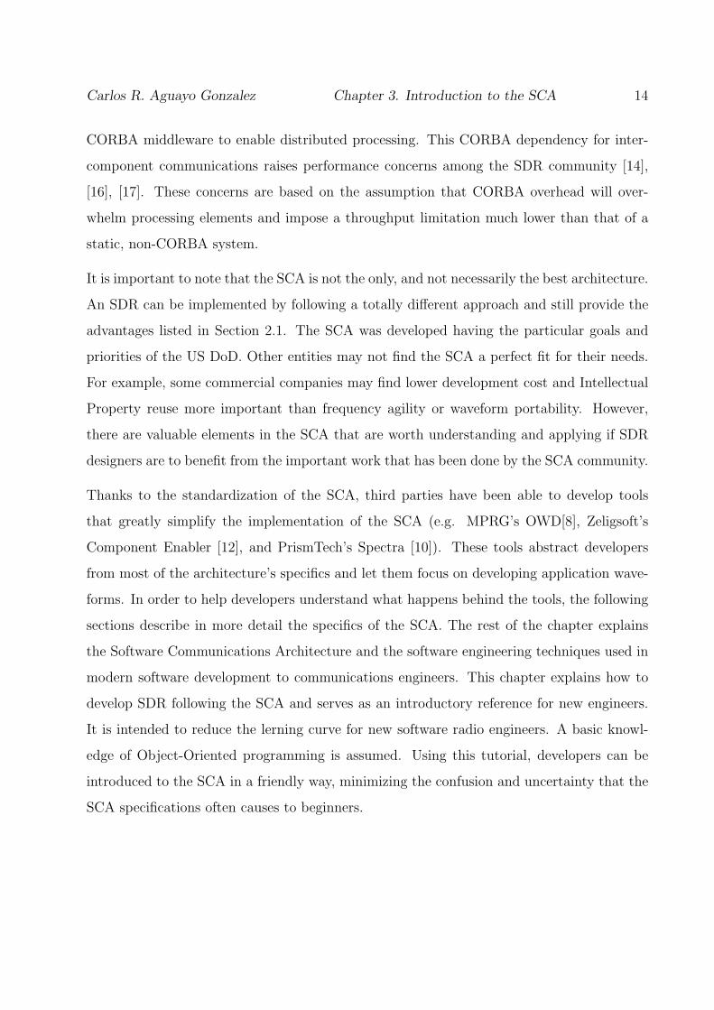
CORBA middleware to enable distributed processing. This CORBA dependency for inter-
component communications raises performance concerns among the SDR community [14],
[16], [17]. These concerns are based on the assumption that CORBA overhead will over-
whelm processing elements and impose a throughput limitation much lower than that of a
static, non-CORBA system.
It is important to note that the SCA is not the only, and not necessarily the best architecture.
An SDR can be implemented by following a totally different approach and still provide the
advantages listed in Section 2.1. The SCA was developed having the particular goals and
priorities of the US DoD. Other entities may not find the SCA a perfect fit for their needs.
For example, some commercial companies may find lower development cost and Intellectual
Property reuse more important than frequency agility or waveform portability. However,
there are valuable elements in the SCA that are worth understanding and applying if SDR
designers are to benefit from the important work that has been done by the SCA community.
Thanks to the standardization of the SCA, third parties have been able to develop tools
that greatly simplify the implementation of the SCA (e.g. MPRG’s OWD[8], Zeligsoft’s
Component Enabler [12], and PrismTech’s Spectra [10]). These tools abstract developers
from most of the architecture’s specifics and let them focus on developing application wave-
forms. In order to help developers understand what happens behind the tools, the following
sections describe in more detail the specifics of the SCA. The rest of the chapter explains
the Software Communications Architecture and the software engineering techniques used in
modern software development to communications engineers. This chapter explains how to
develop SDR following the SCA and serves as an introductory reference for new engineers.
It is intended to reduce the lerning curve for new software radio engineers. A basic knowl-
edge of Object-Oriented programming is assumed. Using this tutorial, developers can be
introduced to the SCA in a friendly way, minimizing the confusion and uncertainty that the
SCA specifications often causes to beginners.

Carlos R. Aguayo Gonzalez Chapter 3. Introduction to the SCA 15
3.1 SCA Specifications
The SCA specification consists four major areas:
• Software Architecture Definition.
Arguably the most important part of the SCA, defines the structure of SCA imple-
mentations by following a component based approach. We will focus on this area and
explain further in the following sections.
• Hardware Architecture Definition.
Enhances hardware abstraction by representing hardware components in an object
oriented approach
• Security Architecture Definition.
Defines security requirements, boundaries, and functions for the JTRS. This section is
of vital importance for military systems although not required by all other applications
• Application Program Interfaces.
A standard set of predefined interfaces required for component reuse. These interfaces
are defined for complete applications first. They will eventually evolve to encompass
individual components.
Even though all parts of the SCA play an important role in the specification, this thesis
focuses on the Software Architecture Definition. The following is a more detailed description
of the Software Architecture.
3.2 The Software Architecture
The software architecture is based on open infrastructure software for managing and inter-
connecting application resources in a distributed computing environment. It exploits well

Carlos R. Aguayo Gonzalez Chapter 3. Introduction to the SCA 16
known software design patterns [15] and relies on COTS technology. The SCA software
structure, shown in Figure 3.2 [19], divides the system in two layers:
1. Operational Environment
• OS
• Middleware
• Core Framework
• Services
2. Applications
The services included in the SCA operating environment are: the Event Service, Naming
Service, and Log Service. These services support framework and application operations by
enabling communication and location of components and providing the means for storage of
records during system operation. The remaining parts of the SCA software architecture are
described in more detail next.
3.3 The SCA Operating Environment
As its name indicates, the SCA Operating Environment (OE) provides the elements necessary
to run applications. The SCA goals of enhanced component reuse and technology insertion
are achieved by the abstraction from the underlying platform provided by the OE. From
the application’s perspective the OE is always the same, no matter how different the actual
physical and logical platforms are. This unified OE is achieved by abstracting hardware
components, device drivers, and transport mechanisms. The underlying platform can be
composed of one or multiple processors, of different architectures and characteristics, and
distributed across different boards, computers, or networks. All this being transparent to
applications. The OE also provides common mechanisms to manage and control applications

Carlos R. Aguayo Gonzalez Chapter 3. Introduction to the SCA 17
Figure 3.1: SCA Software Structure
and their components. This way, application components also have a layer of abstraction for
their particular implementation, presenting always a known interface to other components
and management elements. Using this approach, a component can be implemented using
specialized hardware or software; which can be written in different programming languages
(e.g. C, C++, or java); or can be optimized to run on one particular platform or another; and
that makes no difference in the way components are deployed, connected, and managed when
creating a particular application. The OE is divided into layers which provide increasing
abstraction levels and are described in the following subsections.
3.3.1 Real-Time Operating System
The Real-Time Operating System provides the first layer of abstraction from the hardware.
The RTOS provides multithreaded support for applications and the CF. In order to enhance
portability of applications, the architecture requires a Portable Operating System Interface
(POSIX) standard compliant RTOS. In keeping with the requirement to be scalable to

Carlos R. Aguayo Gonzalez Chapter 3. Introduction to the SCA 18
platforms that are resource limited, the SCA defines an Application Environment Profile
(AEP), which is a subset of POSIX containing only those elements required to support
SCA functionality. While CF components are allowed to use the complete set of interfaces
provided by the RTOS, applications are only allowed to use the services defined in the SCA
AEP. This restriction is necessary for portability purposes. A notional relationship of the OE
and Applications to the AEP is shown in Figure 3.2 [19]. The RTOS provides the following
services:
• Process management
• Process creation
• Inter-process communication
• Timing services
• Input/output management
• Scheduling management (for real time OS)
• File Systems
3.3.2 Object Request Broker
The Common Object Request Broker Architecture (CORBA) is the backbone of the soft-
ware architecture. The SCA indicates the use of minimum-CORBA, as standardized by
the Object Management Group (OMG) [1], to provide transparent exchange of information
across different components. This middleware provides a layer of abstraction between the
application and the specifics of the RTOS and lower layers. It provides a flexible flow of
information across the software bus.

Carlos R. Aguayo Gonzalez Chapter 3. Introduction to the SCA 19
Figure 3.2: Notional Relationship of OE and Applications to SCA AEP

Carlos R. Aguayo Gonzalez Chapter 3. Introduction to the SCA 20
CORBA provides a component-oriented system with the ability to distribute applications
seamlessly. In a given appliation, different components can be deployed on different proces-
sors, platforms, boards, computers or networks and yet appear as if they were local to
the application. Even though CORBA is not the only available middleware (Microsoft’s
DCOM [6] and Sun’s Java/RMI are other examples) its simplicity, openness, and platform
independence made it the preferred option. Because CORBA is only a specification, it can
be implemented for any platform and operating system, including Linux, Windows, and any
other real-time OS, allowing clients to perform requests on remote servers as a simple local
call, independently of the actual location of the server. The logical bus delivered by the ORB
enables the platform independence and flexibility of deployment necessary for achieving the
envisioned waveform portability.
There have been concerns about the performance overhead cost of a CORBA implemen-
tation that would overwhelm the whole system. While this is a valid concern, there is a
great variety of highly optimized CORBA implementations which reduce the performance
penalty (e.g. omniORB [7] and PrismTech’s e*ORB [10]). Most of CORBA delays are due
to transport mechanisms [9]. The standard transport protocol distributed with CORBA im-
plementations is the Internet Inter-ORB Protocol (IIOP) which relies on TCP/IP, causing
long and non-deterministic transport delays. In order to avoid this dependency on IIOP, the
OMG developed the Extensible Transport Famework (ETF) which allows custom, optimized
transport implementations to be plugged into the ORB.
CORBA is a core part of the SCA. Even when development tools can isolate developers from
the details of CORBA, it is important for SCA SDR engineers to have a good understanding
of it. An in-depth description of CORBA is beyond the scope of this thesis; however, we
will describe in one paragraph how CORBA works from the SCA perspective. First, any
CORBA component is born by defining its interfaces in IDL. These IDL interfaces are passed
through the specific IDL compiler of the ORB implementation (omniIDL for omniORB or
idlcpp for e*ORB). This compiler will create the mappings of the interfaces to the specific
platform where they will be deployed (e.g. C, C++, java, etc). The compiler creates two

Carlos R. Aguayo Gonzalez Chapter 3. Introduction to the SCA 21
Figure 3.3: Communication Between CORBA Components
different sets of bindings: one skeleton for servants; and one stub, for clients. In the C++
case, the skeleton contains a set of pure virtual functions that implement the interfaces
defined in IDL. These virtual functions have to be overwritten by the actual functional code
when implementing the servants. The stubs contain definitions of the same functions but are
intended to be included by the clients when requesting a service. At runtime, the components
are registered with the ORB. A client needs a CORBA object reference to interact with a
server, usually getting it using the naming service. Once the client has a reference to the
server the requests can be made using the local stub as if both were collocated. Once the
request has been sent, the ORB takes control. It finds the servant, delivers the messages, and
return the results, all of these actions performed transparently for the client. This process
is shown in Figure 3.3.
3.4 The SCA Core Framework
Before explaining the details of the SCA Core Framework (CF), it is necessary to introduce
the concept itself. A framework is a set of cooperating classes that make up a reusable design
for a specific class of software [15]. A framework defines the architecture and other subtle

Carlos R. Aguayo Gonzalez Chapter 3. Introduction to the SCA 22
issues in a way that is optimized for a certain domain, allowing developers to focus on the
important aspects of the applications. The SCA CF is the heart of the software architecture.
The CF is integrated by a set of open interfaces and services which provide application
designers with a common way of managing application waveforms and its components. It
has its foundation on well known Software Design Patterns and consists of:
• Base Application Interfaces
• Framework Control Interfaces
• Framework Services Interfaces
• Domain Profile
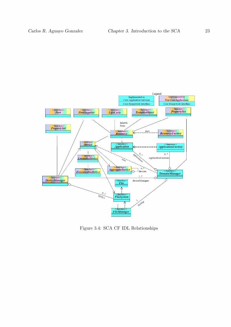
As mentioned before, the SCA CF interfaces are defined in the CORBA Interface Description
Language (IDL). The CF IDL relationships are shown in Figure 3.4 [19]. These IDL interfaces
define the methods and attributes required to describe a component. Interfaces described in
IDL are programming language independent and can be compiled in a variety of languages,
including Java and C++.
3.4.1 Base Application Interfaces
Base Application Interfaces are implemented by all application components. It includes
the Resource interface, shown in Figure 3.5, which provides a common interface for the
control and configuration of software components. Every component in an SCA waveform is
considered a Resource. When creating an SCA component, a developer must implement every
method in the Resource interface in addition to the particular component’s functionality.
This interface enables component processing control (i.e. start and stop behavior). It inherits
from the following base interfaces:
• LifeCycle used to initialize or release the Resource
Carlos R. Aguayo Gonzalez Chapter 3. Introduction to the SCA 23
Figure 3.4: SCA CF IDL Relationships

Carlos R. Aguayo Gonzalez Chapter 3. Introduction to the SCA 24
Figure 3.5: Resource Interface UML Model
• TestableObject used to test Resource (i.e. BIT)
• PropertySet provides operations to configure and query Resource properties.
• PortSupplier provides an operation to get a port object reference
A UML model of the Resource interface is presented in Figure 3.5 [19]. Besides Resource,
the Base Application Interfaces include Port and ResourceFactory. The Port interface is
used to connect Resource components. The ResourceFactory is an optional interface, which
is modeled after the Factory design pattern [15] and is used to create and tear down Resource
components.
We are going to explain the concept of “port” and the Port interface because of its opera-
tion can be somewhat confusing, especially for developers not familiar with component-based
software. A “port” is a logical element that allows a component to request or provide infor-
mation. Every time a component exchanges data or control information with a component
other that the CF, it does it through a port. Ports are classified into UsesPort and Pro-
videsPort. From the client-server point of view, the client “uses” the port and the server

Carlos R. Aguayo Gonzalez Chapter 3. Introduction to the SCA 25
“provides” it. “Ports” can implement one or more IDL interfaces, however, a “uses” port
must have a pointer to the right stub when connecting to a “provides” port.
The Port interface, as can be seen in Figure 3.4 (top left), does not inherit from another
interface and no interfaces inherit from it. This interface provides components with the
connect and disconnect functionality necessary to assemble waveforms. Because only the
component using the port needs to keep a pointer to the provider, only the user component
needs to implement the Port interface.
3.4.2 Framework Control Interfaces
The Framework Control Interfaces provide management and control behavior to the CF.
Thanks to these interfaces, it is possible to deploy, configure, and manage all different com-
ponents in the system in a consistent way. This set of interfaces can be further divided in
two: Device-related Interfaces and Domain Management Interfaces.
The Device-related interfaces allow the interaction with physical hardware devices by provid-
ing a layer of abstraction for the rest of the framework. This abstraction allows non-CORBA-
enabled elements to interact with other components in the application and allows the frame-
work to control them. These interfaces are of particular interest to hardware engineers and
sofware engineers traditionally in charge of developing the enabling drivers. Device-related
interfaces, shown in Figure 3.6, include: Device, LoadableDevice, ExecutableDevice, Aggre-
gateDevice, and DeviceManager
The Device interface provides the framework with a logical representation for simple hard-
ware devices. The Device interface is a special kind of resource that acts as a proxy with
the ability to interact with a particular piece of hardware. Typically, there is one Device per
hardware device. This interface also provides state management and defines the capacity
model of the physical device. An ASIC or a dedicated piece of hardware is a typical example
of physical hardware represented by the Device interface.

Carlos R. Aguayo Gonzalez Chapter 3. Introduction to the SCA 26
The LoadableDevice interface extends the functionality of Device. It adds software loading
and unloading capabilities to modify the runtime behavior of the physical element. FPGAs
are typical examples of hardware components that are represented with this interface.
ExecutableDevice interface expands the previous interface by adding execute and terminate
behavior. Typical examples for this interface are General Purpose Processors (GPP), but any
processor with multithreaded capabilities can be represented by it. Depending on the under-
lying OS, the execution capabilities can be applied to instantiate a new program (process)
or a new function (thread). The ExecutableDevice interface is intended to launch Resource
components. In a way, it has the same functionality as a ResourceFactory. The difference
between ResourceFactory and ExecutableDevice is that an ExecutableDevice can be launched
remotely by a DeviceManager and be instantiated dynamically, allowing runtime reconfigu-
ration of the physical platform (e.g. adding new processing boards to a deployed system).
AggregateDevice is sort of a grouping interface. It is used to represent composite devices,
which can be made of multiple logical devices but present a single interface to the rest of
the domain.
The last of the device-related interfaces is DeviceManager. This interface is used to manage
a set of logical devices and services. Usually, this interface is used to represent a CORBA-
enabled board. When instantiated, DeviceManager creates a file system for the board it
represents and launches all the logical devices under its control as specified in the Domain
Profile. DeviceManager also obtains the location of DomainManager and registers itself in
the domain. An explanation of the information contained in the Domain Profile will be given
later in this work. Figure 3.6 shows the UML models for the family of Device Interfaces.
So far, all the interfaces in the CF are dependent on the particular waveform being im-
plemented or the specific platform used. We will call them application-dependent. The
remaining interfaces are implemented by framework providers and have identical behavior,
independently of the application and platform they are supporting. Domain-Management
Interfaces allow a centralized entity to have control over the whole radio domain. There are

Carlos R. Aguayo Gonzalez Chapter 3. Introduction to the SCA 27
Figure 3.6: Device Interface Family UML Model
three main interfaces in this category: Application, ApplicationFactory, and DomainMan-
ager.
The Application interface is modeled after the “Container” pattern [15]. As the name of the
pattern implies, this interface provides a container for resources that make up a waveform.
It allows the CF to interface with the waveform in a general way, without knowing the
particular application that was instantiated. In other words, a waveform will be treated
the same way no matter if it implements WCDMA or 802.11g. This interface allows the
interaction with the waveform for control, configuration, status, and tear-down. When the
application is terminated, this interface will return the allocated capacities to host devices.
The ApplicationFactory interface, which is modeled after the “factory” design pattern [15],
is used to create an instance of a specific type of application in the domain. The Applica-
tionFactory provides a general procedure to instantiate waveforms, but obtains the details of
which particular application from outside the framework implementation. These details are
provided by the user by means of the Domain Profile. ApplicationFactory reads the Domain
Profile, explained in Section 3.4.4, to obtain a list of the components that comprise the appli-
cation, their location and their respective connections. With this knowledge, the application
factory allocates capacities in the required Devices, launches the required components, es-

Carlos R. Aguayo Gonzalez Chapter 3. Introduction to the SCA 28
Figure 3.7: Application Factory Behavior Instantiation/Deployment
tablishes the respective connections, and performs the initial configuration and initialization.
The implementation of ApplicationFactory should find the best match to allocate component
based on the property model. However, the developer can force a deployment layout by pro-
viding a DeviceAssignment sequence. This sequence is a list of component-host device pairs.
When ApplicationFactory is establishing the connections between all different components,
it calls getPort from the PortProvider interface to get a reference to both the “uses” and the
“provides” ports. It then calls connectPort in the usesport with the provider as a parameter.
The uses port narrows this reference to the expected interface and stores it. After creating
an application ApplicationFactory returns an instance of the Application interface to allow
the interaction with the newly created waveform. Figure 3.7 provides a graphical description
of the simplified operation of ApplicationFactory.
The DomainManager interface controls and maintains the overall state of the radio. It
creates a FileManager that will enclose the FileSystem(s) of every DeviceManager under its
domain, as explained in the next subsection. At instantiation, DomainManager also sets up
the naming context for the radio in the CORBA naming service. DomainManager provides
Carlos R. Aguayo Gonzalez Chapter 3. Introduction to the SCA 29
registration interfaces for DeviceManagers, Devices, Applications and Services. It manages
the access to registered device managers and installed applications. It also provides the
interfaces for user interaction and user interfaces.
3.4.3 Framework Services Interfaces
The last set of interfaces in the CF are Framework Services Interfaces which support both
core and non-core applications. This set of interfaces includes three interfaces that are used
by clients for all file access:
• File This interface provides access to files within the radio. It provides access to basic
file operations, e.g. read, write, close, etc.
• FileSystem This interface provides remote access to physical file systems. It allows
creation, deletion, copying, etc. of files. Typically a FileSystem is limited to one piece
of hardware or a single OS.
• FileManager This interface allows the management of multiple distributed FileSys-
tems. It can be seen as a root file system which mounts and unmounts other file
systems. In fact, it looks like a FileSystem to the client.
3.4.4 Domain Profile
All different elements of the SCA Software Architecture –hardware devices, software com-
ponents, and waveforms– are described by a set of files that are collectively referred to
as the Domain Profile. These files describe the interfaces, functional capabilities, proper-
ties, inter-dependencies, interconnections, and logical location of each and every component
within the domain. These descriptions are provided in eXtensible Markup Language (XML)
files. A visual description of the relationships among Domain Profile descriptors is shown in
Figure 3.8 [19].

Carlos R. Aguayo Gonzalez Chapter 3. Introduction to the SCA 30
Listed below are the eight different kinds of XML files in the Domain Profile.
• Software Package Descriptor (SPD) describes component (CORBA and non-
CORBA) implementations
• Property File (PRF) describes properties for a component.
• Software Component Descriptor (SCD) describes a CORBA component charac-
teristics
• Software Assembly Descriptor (SAD) describes an application’s deployment char-
acteristics
• Device Configuration Descriptor (DCD) describes configuration characteristics
for a DeviceManager
• DomainManager Configuration Descriptor (DMD) describes configuration char-
acteristics for a DomainManager.
• Device Package Descriptor (DPD) identifies a class of hardware device and its
characteristics
• Profile Descriptor describes a type of file (SAD, SPD, DCD, DMD) along with the
file name.
All different files in the Domain Profile have important functions. However, some descriptors
of special importance for understanding the SCA Software Architecture are described below.
Application waveforms are described by the SAD file. It includes a list of the component
instances and their implementation, their logical location requirements as well as the con-
nections between them. The SAD file references an SPD file for each of the components
in the waveform. The SPD file describes one or more implementations of the components.
The interfaces provided and used by each component are described in the SCD file, and a
reference to this file is included in the SPD. The particular properties of each component
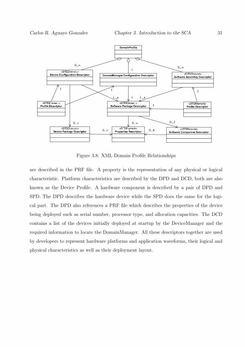
Carlos R. Aguayo Gonzalez Chapter 3. Introduction to the SCA 31
Figure 3.8: XML Domain Profile Relationships
are described in the PRF file. A property is the representation of any physical or logical
characteristic. Platform characteristics are described by the DPD and DCD, both are also
known as the Device Profile. A hardware component is described by a pair of DPD and
SPD. The DPD describes the hardware device while the SPD does the same for the logi-
cal part. The DPD also references a PRF file which describes the properties of the device
being deployed such as serial number, processor type, and allocation capacities. The DCD
contains a list of the devices initially deployed at startup by the DeviceManager and the
required information to locate the DomainManager. All these descriptors together are used
by developers to represent hardware platforms and application waveforms, their logical and
physical characteristics as well as their deployment layout.

Carlos R. Aguayo Gonzalez Chapter 3. Introduction to the SCA 32
3.5 SCA Waveforms
SCA waveforms are reusable, portable, modular, distributed applications dedicated to per-
form radio signal processing. SCA waveforms are made from one or more Resource compo-
nents. Waveforms are described by a SAD file and deployed by the CF ApplicationFactory.
The waveform components send and receive data and control information through the
CORBA logical bus. The portability of SCA waveforms is enabled by the abstraction of
the underlying platform provided by the Operating Environment. The application developer
does not need to know the underlying platform or final deployment configuration at devel-
opment time. Those details are sorted out at runtime by the CF with information obtained
from the domain profile.
Each application component should perform exactly operation, although the optimum gran-
ularity is still a research topic and the tradeoff between reusability and overhead should
be considered. Each component is described by an IDL interface and must implement the
resource interface besides the particular interfaces for additional data or control information.
For data exchange usually the interface will be push packet(), as presented in the SCA API
building blocks [19]. A component can have as many ports as needed, and can be connected
to as many other components as necessary. The only requirement is to support the Resource
interface so the CF can manage it.
Proper development of SCA waveforms involves building a waveform analysis model (develop
UML models and simulations), building waveform language interfaces (develop IDL interfaces
and create stubs and skeletons), building waveform component implementations (implement
the actual signal processing components), and integrating waveform components (create the
XML Domain profile). While it is not necessary to follow all these steps strictly, doing
it ensures a smooth path, easier integration, proper waveform documentation, and enables
the application of automatic testing strategies. Fortunately there are tools that can help
developers in every single stage of the development. Some of the tools are distributed for
Carlos R. Aguayo Gonzalez Chapter 3. Introduction to the SCA 33
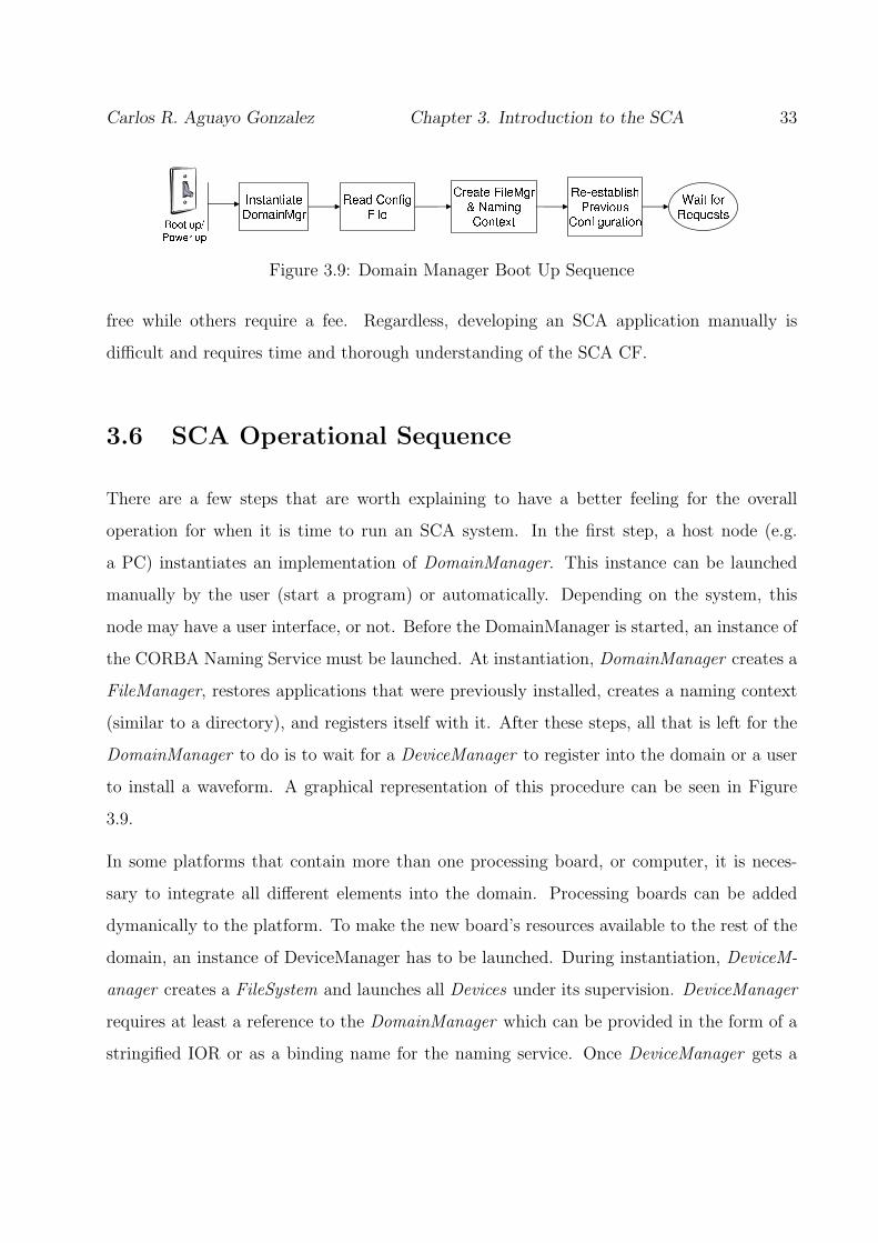
Figure 3.9: Domain Manager Boot Up Sequence
free while others require a fee. Regardless, developing an SCA application manually is
difficult and requires time and thorough understanding of the SCA CF.
3.6 SCA Operational Sequence
There are a few steps that are worth explaining to have a better feeling for the overall
operation for when it is time to run an SCA system. In the first step, a host node (e.g.
a PC) instantiates an implementation of DomainManager. This instance can be launched
manually by the user (start a program) or automatically. Depending on the system, this
node may have a user interface, or not. Before the DomainManager is started, an instance of
the CORBA Naming Service must be launched. At instantiation, DomainManager creates a
FileManager, restores applications that were previously installed, creates a naming context
(similar to a directory), and registers itself with it. After these steps, all that is left for the
DomainManager to do is to wait for a DeviceManager to register into the domain or a user
to install a waveform. A graphical representation of this procedure can be seen in Figure
3.9.
In some platforms that contain more than one processing board, or computer, it is neces-
sary to integrate all different elements into the domain. Processing boards can be added
dymanically to the platform. To make the new board’s resources available to the rest of the
domain, an instance of DeviceManager has to be launched. During instantiation, DeviceM-
anager creates a FileSystem and launches all Devices under its supervision. DeviceManager
requires at least a reference to the DomainManager which can be provided in the form of a
stringified IOR or as a binding name for the naming service. Once DeviceManager gets a

Carlos R. Aguayo Gonzalez Chapter 3. Introduction to the SCA 34
Figure 3.10: Device Manager Boot Up Sequence
Figure 3.11: Application Create Sequence
CORBA reference of the DomainManager, it registers itself with the domain and makes all
of its devices, and services, available to the rest of the system. A graphical representation of
this sequence of events can be seen in Figure 3.10.
Once the domain has been established, the system is ready to deploy waveforms. The steps
perfomed when creating a waveform are shown in Figure 3.11. First, the DomainManager
instantiates an ApplicationFactory for each SAD file in the domain. The user decides which
application is going to be deployed and requests the specific ApplicationFactory to create
it. The user can also force a particular deployment layout by providing a device assignment
sequence. ApplicationFactory then parses the SAD file to obtain a list of the components
to deploy and their logical location. If the components are assigned to a given Device, then
they are loaded and launched there, if necessary. If they are not listed in the DeviceAssign-
ment sequence, then ApplicationFactory must find a good match based on the configured
capacities of the devices in the system and the allocation requirements of the components.
ApplicationFactory can also request a ResourceFactory to create the required components.
Once all the components have been instantiated, ApplicationFactory proceeds to establish all
the connections, as explained in Section 3.4.2. After the connections have been established,
ApplicationFactory creates an instance of Application and returns its reference to the user.
Carlos R. Aguayo Gonzalez Chapter 3. Introduction to the SCA 35
3.7 The Open-Source SCA Implementation::Embedded
OSSIE
The Open Source SCA Implementation::Embedded (OSSIE) Project [8] is an initiative by
the Mobile and Portable Radio Research Group (MPRG) at Virginia Tech to provide an
open-source implementation of the SCA. This implementation was developed following the
directives of simplicity and easy expandability. OSSIE is written in C++ and uses omniORB
and the Xerces XML parser, both of which are openly available. OSSIE is developed for
Linux and specifically supports the Fedora distribution. Cygwin or VMWare can be used to
run OSSIE on Windows. The first version of OSSIE was released in July of 2004 and has
been in constant improvement since then.
Although OSSIE is not a “certified” implementation of the SCA for the time being, it
provides an excellent framework for experimental and prototype development due to its
simplicity, shallow learning curve, and free distribution. It only implements the minimum
required elements of the SCA Software Architecture to operate. It also makes some basic
assumptions (e.g. only one implementation per component, a DeviceAssignmentSequence
is provided when deploying a waveform) that simplify the development, making it suitable
for efficient, flexible implementations. An OSSIE release includes source files to build two
libraries: one containing the required XML parsers (ossieparser), and other one containing
an implementation of the SCA CF (ossiecf). Besides these libraries, a sample application
can be obtained which demonstrates the basic usage of OSSIE. Source code for both libraries
and the sample application is released under the LGPL and GPL.
The ossiecf part of the distribution contains implementations of most of the interfaces de-
scribed in the Core Framework. Some of these implementations are application independent
and can be included in any new systems directly. While others are implementation dependent
and need to be rewritten to match the exact requirements for the application. For example,
the implementations of DomainManager and ApplicationFactory can be used directly out

Carlos R. Aguayo Gonzalez Chapter 3. Introduction to the SCA 36
of the box. Implementations of the Resource interface, and its parent interfaces (LifeCycle,
PortSupplier, PropertySet, etc) are application dependent and are implemented as dummy
interfaces. OSSIE also provides implementation of other application dependent interfaces
that can be used out of the box in most cases. The implementation of ExecutableDevice
was developed for a General Purpose Processor in a PC. The decision of providing empty
implementations of application dependent interfaces was taken to give developers a skeleton
containing the right syntax and structure, facilitating their work.
Other examples of available SCA frameworks are: SCARI from Communication Research
Center Canada [2], dmTK from Harris Corporation [4].
3.8 The Hardware Abtraction Layer – Connectivity
As mentioned before, the SCA is somewhat GPP centric. It assumes that the underlying
platform contains at least one GPP to perform signal processing. However, increasing data
rates and the relatively limited processing efficiency of GPPs, impose serious constrains
for SCA implementations. This the reason why traditional radio developers have relied on
specialized hardware (e.g. DSPs and FPGAs) to implement radio systems for decades. The
SCA community identified these issues and developed a specification to include specialized
HW into the framework, the Hardware Abstraction Layer –Connectivity (HAL-C). These
specification describes a set of APIs that would enable specialized hardware to bypass the
ORB logical bus when connected to another component. In other words, this specification
will allow non-CORBA components executing in DSPs, FPGAs, and ASICs to avoid the use
of CORBA while still maintaining portability.
HAL-C specifies a hardware platform-independent means for communication between soft-
ware components running on specialized hardware. This is achieved by specifying a com-
munications API, minimizing the effect of the actual hardware platforms communication
mechanisms on the software design. The ultimate goal of this API is to reduce the need

Carlos R. Aguayo Gonzalez Chapter 3. Introduction to the SCA 37
of significan component rewrite during portings. For processing elements that support a
C runtime (e.g. DSPs), the HAL-C API consists of 4 functions that implement retrieving
Endpoint handles, sending data to Endpoints, receiving data at endpoints, and registering
callbacks. For processing elements such as FPGAs, the API consists of a data bus, as well
as associated clock and control signals. The HAL-C APIs are considered part of the SCA
operating environment.
The HAL-C specification is relatively new and needs further refinment. Mixed reviews have
been received while the actual functionality of the specification has been questioned. By the
time of this writing, the SCA version 3.0 has been labeled as “unsupported” in the JTRS
website. In this thesis we follow a different approach to integrate specialized hardware into
the SCA. Given the advances in ORB implementations and the improvements in developing
tools, we integrate DSPs into the SCA as another CORBA-enabled processing element.
This approach enables all the advantages of a full blown implementation of the SCA with
the benefits of an optimized platform for signal processing. The implementation of this
approach is described in detail in the following Chapter.

Chapter 4
Implementing the SCA Core
Framework on a C64 Platform
4.1 OSSIE-TI System Architecture
In this project we designed and developed an SCA implementation for a homogeneous TI
DSP platform. No General Purpose Processors are involved in signal processing. We lever-
aged our existing implementation of OSSIE, an open-source implementation of the SCA core
framework [8], by porting it to the C64 platform. The whole system was developed following
the SCA 2.2.1 specifications and implemented in C++. Minor deviations from the specs were
required which did not affect the functionality or portability of the framework or applications.
Our development environment was TI’s Code Composer Studio running in a Windows ma-
chine. Most of the development was done using the Device Accurate simulator of the C6000.
The final target platform is a Signal Master Quad from Lyrtech. Communications with the
physical hardware was established using a USB JTAG emulator.
38

Carlos R. Aguayo Gonzalez Chapter 4. Implementing the C64 SCA CF 39
Figure 4.1: Software Structure
4.2 Software Architecture
The general software architecture can be seen in Figure 4.1. There, three different com-
ponents of the SCA Operational Environment (OE), the Core Framework (CF), ORB, and
operating system, are shown. We excluded the services (Log, Event, and Naming Services)
from the initial implementation. The purpose of the SCA OE is to abstract the application
from the underlying platform facilitating application development and enhancing portability.
In this project we focused in only including openly available software to reduce development
time. This decision makes it easier for other entities to use our framework. In this project
we used OSSIE as the CF, e*ORB from PrismTech as ORB, and DSP/BIOS as RTOS.
DSP/BIOS is a scalable real-time multitasking operating system designed specifically for

Carlos R. Aguayo Gonzalez Chapter 4. Implementing the C64 SCA CF 40
the TMS320 family of DSPs [11]. It is developed and maintained by Texas Instruments.
DSP/BIOS is built in modules which allows developers to redude the footprint to a mini-
mum by only integrating the modules that are strictly necessary for operation. It supports
preemptive multithreaded operation thanks to a real time scheduler. It also provides mem-
ory management modules for low overhead dynamic memory allocation. The C6000 family
of processors does not include a memory management unit.
The ORB used in this project is PrismTech’s e*ORB SDR C++ version for DSP. This was
a custom port of their commercially available C version. However, Prismtech has released
this version available to the general public [10]. e*ORB is a very optimized, modular im-
plementation of minimum-CORBA as standardized by the OMG. This particular version is
optimized for the C6000 platform. e*ORB also supports the Extensible Transport Layer
(ETF) which allows to plug in optimized custom transports.
The application components are for this framework are developed the same way of traditional
SCA components. Only minor modifications, explained later in the thesis, are required to
adapt them to the real-time scheduler. Another aspect is that different is the access calls
to OS services, which have to compain with DSP/BIOS standards and are no necessarily
POSIX compliant, as required by the SCA.
4.3 Platform
The target platform for this project is the SignalMaster Quad C6416 from Lyrtech [5].
This high performance board contains 4 TI C6416 DSPs and 2 Xilinx Virtex II FPGAs.
The system runs at 720 MHz and has 128Mbytes of SDRAM memory per DSP. A block
diagram of the SignalMaster board is shown in Figure 4.2 [5]. The board has two clusters.
Each cluster contains 1 FPGA and 2 DSPs. The high speed bus between both FPGAs is
implemented using LVDS. The communication between two DSPs within the same cluster
can be implemented using shared memory or a proprietary protocol developed by Lyrtech
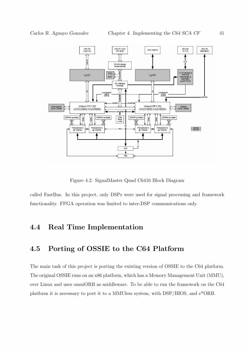
Carlos R. Aguayo Gonzalez Chapter 4. Implementing the C64 SCA CF 41
Figure 4.2: SignalMaster Quad C6416 Block Diagram
called FastBus. In this project, only DSPs were used for signal processing and framework
functionality. FPGA operation was limited to inter-DSP communications only.
4.4 Real Time Implementation
4.5 Porting of OSSIE to the C64 Platform
The main task of this project is porting the existing version of OSSIE to the C64 platform.
The original OSSIE runs on an x86 platform, which has a Memory Management Unit (MMU),
over Linux and uses omniORB as middleware. To be able to run the framework on the C64
platform it is necessary to port it to a MMUless system, with DSP/BIOS, and e*ORB.
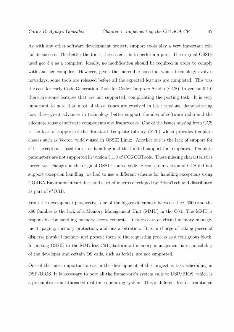
Carlos R. Aguayo Gonzalez Chapter 4. Implementing the C64 SCA CF 42
As with any other software development project, support tools play a very important role
for its success. The better the tools, the easier it is to perform a port. The original OSSIE
used gcc 3.4 as a compiler. Ideally, no modification should be required in order to comply
with another compiler. However, given the incredible speed at which technology evolves
nowadays, some tools are released before all the expected features are completed. This was
the case for early Code Generation Tools for Code Composer Studio (CCS). In version 5.1.0
there are some features that are not supported, complicating the porting task. It is very
important to note that most of those issues are resolved in later versions, demonstrating
how these great advances in technology better support the idea of software radio and the
adequate reuse of software components and frameworks. One of the issues missing from CCS
is the lack of support of the Standard Template Library (STL) which provides template
classes such as Vector, widely used in OSSIE Linux. Another one is the lack of support for
C++ exceptions, used for error handling and the limited support for templates. Template
parameters are not supported in version 5.1.0 of CCS CGTools. These missing characteristics
forced vast changes in the original OSSIE source code. Because our version of CCS did not
support exception handling, we had to use a different scheme for handling exceptions using
CORBA Environment variables and a set of macros developed by PrismTech and distributed
as part of e*ORB.
From the development perspective, one of the bigger differences between the C6000 and the
x86 families is the lack of a Memory Management Unit (MMU) in the C64. The MMU is
responsible for handling memory access requests. It takes care of virtual memory manage-
ment, paging, memory protection, and bus arbitration. It is in charge of taking pieces of
disperse physical memory and present them to the requesting process as a contiguous block.
In porting OSSIE to the MMUless C64 platform all memory management is responsibility
of the developer and certain OS calls, such as fork(), are not supported.
One of the most important areas in the development of this project is task scheduling in
DSP/BIOS. It is necessary to port all the framework’s system calls to DSP/BIOS, which is
a preemptive, multithreaded real time operating system. This is different from a traditional

Carlos R. Aguayo Gonzalez Chapter 4. Implementing the C64 SCA CF 43
fair-share OS because the active task with the highest priority will be scheduled for execution,
no matter how many other tasks are waiting or for how long. This characteristic allows
deterministic execution, crucial in real-time systems. The DSP/BIOS scheduler allows the
developer to start and stop tasks, as well as to modify its properties. The difference between
DSP/BIOS and a traditional fare-share OS is that in DSP/BIOS the developer is responsible
for the scheduling and close attention must be put in priority assignment since some tasks
may starve.
In an SCA system, only one domain manager is needed while there can be an arbitrary
number of devices, device managers, file systems and applications. For this project, we
decided to separate the computing nodes based on the interfaces they were hosting. The “host
node” hosts an instance of the domain manager, while a “remote node” hosts an instance
of Device Manager and other Devices. This deployment strategy can be seen in Figure 4.3.
There are other possible strategies, for example having a node host both DomainManager
and DeviceManager, while the rest of the nodes in the platforms only host Devices. However,
we decided in this approach to stress out our implementation and see the performance of a
system that would mimic the implementation in a GPP or a PC.
4.6 XML Parsing Strategy and implementation
The SCA specification requires the reading of the Domain Profile at runtime, described in
XML files, to obtain deployment and configuration information. All software components and
waveforms are described in the Domain Profile in XML files. For example, the Application
Factory interface of the CF must read a SAD file in order to know what components are
included in a given waveform and how they are connected. The whole task of decoding an
XML file is a little complicated for a DSP and there are not so many tools available to perform
this task, as there are for the PC world. In order to facilitate the development, reduce
the memory requirements, and speed execution, we developed a two-step parsing scheme
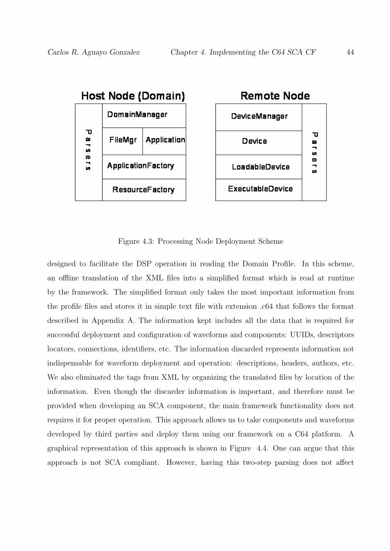
Carlos R. Aguayo Gonzalez Chapter 4. Implementing the C64 SCA CF 44
Figure 4.3: Processing Node Deployment Scheme
designed to facilitate the DSP operation in reading the Domain Profile. In this scheme,
an offline translation of the XML files into a simplified format which is read at runtime
by the framework. The simplified format only takes the most important information from
the profile files and stores it in simple text file with extension .c64 that follows the format
described in Appendix A. The information kept includes all the data that is required for
successful deployment and configuration of waveforms and components: UUIDs, descriptors
locators, connections, identifiers, etc. The information discarded represents information not
indispensable for waveform deployment and operation: descriptions, headers, authors, etc.
We also eliminated the tags from XML by organizing the translated files by location of the
information. Even though the discarder information is important, and therefore must be
provided when developing an SCA component, the main framework functionality does not
requires it for proper operation. This approach allows us to take components and waveforms
developed by third parties and deploy them using our framework on a C64 platform. A
graphical representation of this approach is shown in Figure 4.4. One can argue that this
approach is not SCA compliant. However, having this two-step parsing does not affect
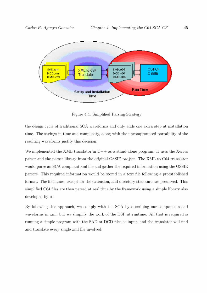
Carlos R. Aguayo Gonzalez Chapter 4. Implementing the C64 SCA CF 45
Figure 4.4: Simplified Parsing Strategy
the design cycle of traditional SCA waveforms and only adds one extra step at installation
time. The savings in time and complexity, along with the uncompromised portability of the
resulting waveforms justify this decision.
We implemented the XML translator in C++ as a stand-alone program. It uses the Xerces
parser and the parser library from the original OSSIE project. The XML to C64 translator
would parse an SCA compliant xml file and gather the required information using the OSSIE
parsers. This required information would be stored in a text file following a preestablished
format. The filenames, except for the extension, and directory structure are preserved. This
simplified C64 files are then parsed at real time by the framework using a simple library also
developed by us.
By following this approach, we comply with the SCA by describing our components and
waveforms in xml, but we simplify the work of the DSP at runtime. All that is required is
running a simple program with the SAD or DCD files as input, and the translator will find
and translate every single xml file involved.

Carlos R. Aguayo Gonzalez Chapter 4. Implementing the C64 SCA CF 46
4.7 File System
Our hardware platform does not have long-term storage capability. Therefore, only a partial
file system is implemented. In this project, we borrow the host’s computer’s hard drive and
file system to be used by the framework. This was accomplished by using the CCS I/O
utilities and the JTAG interface.
To implement the filesystem we relied on IO functions of TI run-time support library. How-
ever, the access allowed by this library is limited. The limitations are found primarily in
directory manipulation. Therefore, functionality such as mkdir, rmdir, mount, and unmount
was not implemented. Only the functionality specified in Table 4.1 is implemented.
Table 4.1: Partial FileSystem Functionality
Interface Operation
read()
File write()
close()
setFilePointer()
remove()
FileSystem exists()
create()
open()
FileManager
4.8 Software Component Deployment
The SCA specifies two equivalent mechanisms to launch software components. One is using
a ResourceFactory and the other one using an ExecutableDevice. In this project we used the

Carlos R. Aguayo Gonzalez Chapter 4. Implementing the C64 SCA CF 47
resourcefactory interface to deploy components in the host node and an ExecutableDevice
for remote nodes. The ExecutableDevice interface typically represents processors with a
multithreaded operating system capable of launching software components. The executable
device has access to the OS directives to start the component. ResourceFactory performs
the exact same functionality, and is used a local tool to deploy components without the need
of including a DeviceManager. To implement these interfaces in DSP/BIOS, we use the task
scheduler. Every time a new component is requested, a new task is created and scheduled.
The resource factory and executable devices are in charge of managing the new task’s priority.
Because of the lack of a memory management unit and long-term storage capability, it is
necessary to have all the tasks that will be scheduled loaded in program memory before the
operation. When all the tasks are loaded, a simple DSP/BIOS directive can include the
tasks into the scheduler. This approach however, trades off memory footprint and dynamic
deployments. It may be possible to have a dynamic loading of program memory, although
we are not aware of it.
4.9 Sample Application
In order to demonstrate the framework functionality, a sample application was developed.
This application is intended for demonstration purposes and nothing else. No extensive
signal processing is performed. The main goal in developing this sample application is to
verify the operation of the framework and to corroborate the feasibility of deploying SCA
compliant waveforms onto the C64 platform.
The sample application included three simple components as shown in Figure 4.5. In this
waveform, a random stream of 1s and -1s is generated by the Modulator component. The
stream is passed to the Channel component which adds Gaussian noise to both the In-
Phase and Quadrature components of the stream. The Demodulator acts as a sink and
only displays the constellation diagram of the signal. A second waveform was developed,
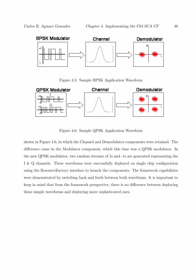
Carlos R. Aguayo Gonzalez Chapter 4. Implementing the C64 SCA CF 48
Figure 4.5: Sample BPSK Application Waveform
Figure 4.6: Sample QPSK Application Waveform
shown in Figure 4.6, in which the Channel and Demodulator components were retained. The
difference came in the Modulator component, which this time was a QPSK modulator. In
the new QPSK modulator, two random streams of 1s and -1s are generated representing the
I & Q channels. These waveforms were successfully deployed on single chip configuration
using the ResourceFactory interface to launch the components. The framework capabilities
were demonstrated by switching back and forth between both waveforms. It is important to
keep in mind that from the framework perspective, there is no difference between deploying
these simple waveforms and deploying more sophisticated ones.

Chapter 5
Results
5.1 Application Deployment
In this section we present the results of deploying applications in our C64 framework. We
are able to successfully deploy both applications described before. We use Code Composer
Studio (CCS) to control the execution, display information and error messages, and input
selection values. At startup, the DomainManager, ApplicationFactory, and ResourceFactory
are instantiated. Immediatelly after all these instantiations, the framework displays a simple
menu and queries the user for the application to install. A snapshot of this stage during a
demonstration is shown in Figure 5.1.
After the selection is made, the requested waveform is deployed. The graphical display ca-
pabilities of CCS are used to visualize the operation of the waveform. A time vs. amplitud
graph is used to display the streams of 1s and -1s generated by the Modulator component,
while a constellation diagram is used to show the signal received at the Demodulator com-
ponent. A snapshot of the operation of the BPSK waveform is shown in Figure 5.2, while
Figure 5.3 shows the QPSK operation. The source code for the framework and applications
is openly available at [8].
49
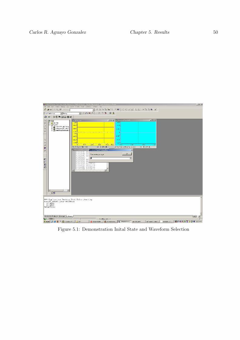
Carlos R. Aguayo Gonzalez Chapter 5. Results 50
Figure 5.1: Demonstration Inital State and Waveform Selection

Carlos R. Aguayo Gonzalez Chapter 5. Results 51
Figure 5.2: BPSK Waveform Operation Snapshot

Carlos R. Aguayo Gonzalez Chapter 5. Results 52
Figure 5.3: QPSK Waveform Operation Snapshot

Carlos R. Aguayo Gonzalez Chapter 5. Results 53
5.2 Profile and Benchmarking
This section presents profiling results of the OSSIE TI CF implementation. Profiling was
performed on the framework and application using two different metrics: memory footprint
and cycle count. The first one is an important metric to represent the extra memory space
necessary to suport the SCA framework. This is a very sensitive are for SDR manufacturers
given that less memory requirements represents cheaper components, smaller buses, smaller
devices, etc. The latter, represents the amount of overhead imposed by the framework in
terms of processing power. This is another important metric because it determines the max-
imum data rate supported by a given implementation. No need to mention how important
this is to radio developers. These results were obtained from a single-chip implementation.
That is all framework and waveform components were collocated within the same processor.
This results do not include the effects of a transport layer. These results were obtained
from a basic implementation, NO OPTIMIZATIONS WERE PERFORMED in either the
framework or the waveform components. All performance tests were carried out using the
C6416 Device Cycle Accurate Simulator and the Code Composer Studio profiler.
It is very important to emphasize that these results represent initial measurements and are
subject to further investigation, validation and more importantly optimization. They only
portray a snapshot in the beginning of an open-source software development.
5.2.1 Memory Footprint
Memory allocation results are obtained from the .MAP file generated by CCS Code Gen-
eration Tools. This file contains a maping of all sections allocated in memory. It includes
program memory and data memory. All dynamic memory allocation requests are served
from a memory pool or heap, which is also included in the MAP file. All profiling results are
presented in 8-bit bytes. It is important to note that each DSP on the SignalMaster Quad
board has 128M of external memory (ERAM) besides the 2K Bytes of on-chip memory
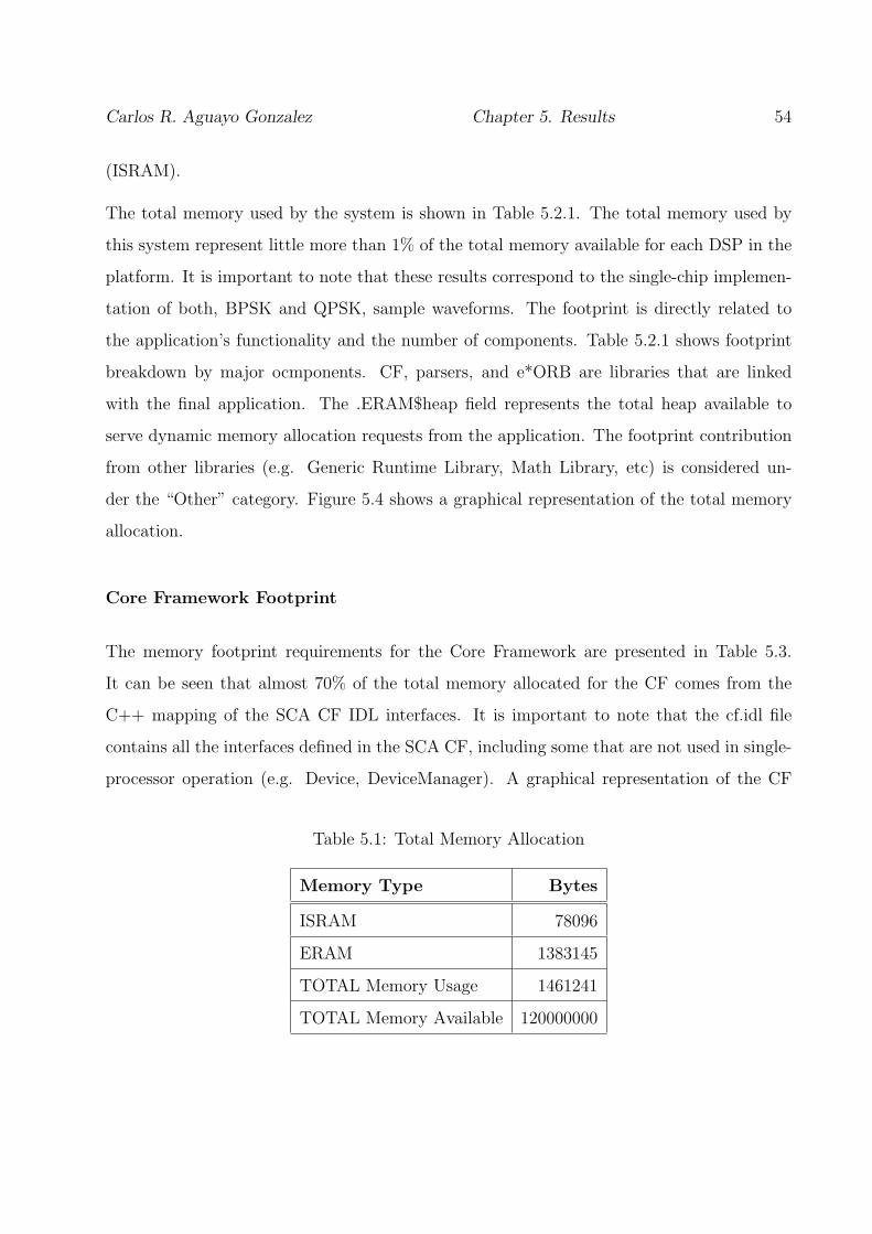
Carlos R. Aguayo Gonzalez Chapter 5. Results 54
(ISRAM).
The total memory used by the system is shown in Table 5.2.1. The total memory used by
this system represent little more than 1% of the total memory available for each DSP in the
platform. It is important to note that these results correspond to the single-chip implemen-
tation of both, BPSK and QPSK, sample waveforms. The footprint is directly related to
the application’s functionality and the number of components. Table 5.2.1 shows footprint
breakdown by major ocmponents. CF, parsers, and e*ORB are libraries that are linked
with the final application. The .ERAM$heap field represents the total heap available to
serve dynamic memory allocation requests from the application. The footprint contribution
from other libraries (e.g. Generic Runtime Library, Math Library, etc) is considered un-
der the “Other” category. Figure 5.4 shows a graphical representation of the total memory
allocation.
Core Framework Footprint
The memory footprint requirements for the Core Framework are presented in Table 5.3.
It can be seen that almost 70% of the total memory allocated for the CF comes from the
C++ mapping of the SCA CF IDL interfaces. It is important to note that the cf.idl file
contains all the interfaces defined in the SCA CF, including some that are not used in single-
processor operation (e.g. Device, DeviceManager). A graphical representation of the CF
Table 5.1: Total Memory Allocation
Memory Type Bytes
ISRAM 78096
ERAM 1383145
TOTAL Memory Usage 1461241
TOTAL Memory Available 120000000

Carlos R. Aguayo Gonzalez Chapter 5. Results 55
Table 5.2: Major Components Contribution
Memory Type Bytes
CF 556555
Parsers 31511
ORB 212412
Application 385624
Sub-Total 1186102
.ERAM$heap 131072
Other 144067
TOTAL Memory 1461241
Figure 5.4: Memory Footprint Summary

Carlos R. Aguayo Gonzalez Chapter 5. Results 56
footprint is shown in Figure 5.5. A know footprint optimization path for the C++ bindings
of IDL interfaces is adding more control to the IDL compiler to enable more selective code
generation (e.g. for specific interfaces generate stub only, or skeletons only, or nothing. This
approach opens the door for potential large improvements depending on how much of the
IDL interfaces are being used. This is a well understood approach although it was not
implemented for this project. Another important qualifier for these results is the absence of
Device-related interfaces. No DeviceManager or Device interfaces were implemented. The
methods in DomainManager relative to Device and service registration and unregistration
are not implemented in this version as well.
The memory footprint occupied by the parsers is shown in Figure 5.6 and Table 5.4.
The different values in subsequent tables represent different sections in the memory map
created by the compiler. A section is a block of code or data that ultimately occupies
contiguous space in the memory map. The compiler creates two basic kinds of sections:
• Initialized sections
.cinit Tables for explicitly initialized global and static variables
.const Global and static const variables that are explicitly initialized and that are
string literals
.pinit Table of constructors to be called at startup
.switch Tables for implementing switch statements.
.text Executable code and constants
• Uninitialized sections
.bss Global and static variables
.stack Stack
.sysmem Memory for malloc functions

Carlos R. Aguayo Gonzalez Chapter 5. Results 57
Table 5.3: Core Framework Memory Footprint Breakdown
CF .text .const .far .pinit .cinit .switch total/comp
cf.obj 218880 46386 1444 4 1532 0 268246
cf s.obj 79808 29656 8 4 0 344 109820
Application impl.obj 41440 9574 8 4 0 0 51026
DomainManager impl.obj 27232 3591 8 4 0 0 30835
ApplicationFactory impl.obj 27008 1723 8 4 0 0 28743
Resource impl.obj 20640 5668 8 4 0 0 26320
FileSystem impl.obj 9952 1699 8 4 0 0 11663
FileManager impl.obj 8384 2470 72 4 76 0 11006
File impl.obj 7008 1324 8 4 0 0 8344
PropertySet impl.obj 3456 860 8 4 0 0 4328
LifeCycle impl.obj 1376 724 8 4 0 0 2112
TestableObject impl.obj 1344 700 8 4 0 0 2056
PortSupplier impl.obj 1344 700 8 4 0 0 2056
TOTAL 556555
Figure 5.5: Core Framework Memory Footprint

Carlos R. Aguayo Gonzalez Chapter 5. Results 58
Table 5.4: Parsers Memory Footprint by class
Parser .text .const .far .pinit total/comp
PRFSimpleProperty.obj 7040 293 8 4 7345
SADParser.obj 3776 34 0 0 3810
SPDParser.obj 2944 12 8 4 2968
SPDImplementation.obj 2272 45 8 4 2329
Connection.obj 1856 0 0 0 1856
SCDParser.obj 1824 91 0 0 1915
DMDParser.obj 1664 5 0 0 1669
ComponentPlacement.obj 1440 16 0 0 1456
SADComponentPlacement.obj 1408 16 0 0 1424
ComponentAssemblyParser.obj 1376 16 0 0 1392
SADComponentInstantiation.obj 1344 19 0 0 1363
ComponentInstantiation.obj 1056 16 0 0 1072
FindBy.obj 864 0 0 0 864
ProvidesPort.obj 800 0 0 0 800
UsesPort.obj 800 0 0 0 800
Port.obj 448 0 0 0 448
TOTAL 31511

Carlos R. Aguayo Gonzalez Chapter 5. Results 59
Application
Table 5.2.1 presents the memory footprint breakdown for the sample waveforms developed.
These results include both BPSK and QPSK components. All the main components in the
application have a very similar footprint as expected. The functionality of these components
is extremely simple and more complex waveforms will require more memory. For the sample
waveforms, most of the memory requirements come from implementing the CF’s Base Ap-
plication Interfaces. Figure 5.7 provides a graphical representation of the memory used by
the sample applications.
e*ORB Footprint
In this section we summarized the memory requirements from e*ORB. These results, shown
in Table 5.2.1, represent a preliminary release of the ORB. Further development and opti-
mization has been performed on e*ORB and these results may not accurately represent the
memory footprint of later releases. No transport layer is included in the results and only the
libraries required for single-processor operation are included. Figure 5.8 presents the results
graphically.
5.2.2 Performance Profile
Cycle requirements were collected for the most significant sections of the OSSIE TI CF
Implementation. In terms of the Core Framework, the sections profiled were Domain initial-
ization and waveform creation. The first one includes Domain Manager Instantiation and
the creation of ApplicationFactory and ResourceFactory. The results of this section are not
application dependent. The latter represents the execution of ApplicationFactory-¿create().
It includes descriptor parsing, task scheduling and initialization, and component connection.
This result depends on the specifics of the intended waveform.

Carlos R. Aguayo Gonzalez Chapter 5. Results 60
Figure 5.6: Parser Memory Footprint
Table 5.5: BPSK/QPSK Sample Application Memory Footprint by class
Component .text .const .cinit .far .pinit .switch Total/comp
ModulateData.obj 38624 10240 20 436 4 0 49324
Channel.obj 38592 10164 20 32 4 0 48812
QPSKModulateData.obj 38400 10245 0 16 4 0 48665
AssemblyController i.obj 37920 9954 20 32 4 0 47930
DecodeData.obj 36096 10004 20 436 4 0 46560
ResourceFactory impl.obj 10656 1180 0 32 4 0 11872
C64Demo.obj 39136 20567 140 108 4 0 59955
C64Demo s.obj 22528 16256 0 16 4 336 39140
PortTypes.obj 23264 528 0 72 4 0 23868
PortTypes s.obj 96 0 0 8 4 0 108
TestApplicationFactory.obj 8576 706 20 84 4 0 9390
TOTAL 385624

Carlos R. Aguayo Gonzalez Chapter 5. Results 61
Figure 5.7: BPSK/QPSK Demo Application Memory Footprint
Table 5.6: e*ORB Memory Footprint by Library
.text .const .cinit .far .pinit total/lib
e mpoa.lib 87648 1261 124 220 52 89305
e orb.lib 112256 3727 1298 914 80 118275
ec os.lib 3104 96 44 16 0 3260
es etf.lib 1536 0 28 8 0 1572
TOTAL 212412
Figure 5.8: e*ORB Memory Footprint

Carlos R. Aguayo Gonzalez Chapter 5. Results 62
5.3 e*ORB Profiling
The performance of the ORB has a great impact on the overall performance of the system.
This is because all inter-component communications are established using CORBA messages.
Two specific test scenarios were used to generate these results:
Invocation: roundtrip cycle count for a simple method invocation with no arguments.
Marshaling: roundtrip cycle count for a simple method invocation with basic arguments.
Three different argument types were evaluated:
1. Single Data Type
2. Array
3. Sequence1
All method implementations were empty. A CORBA::Environment variable must be passed
as an argument on each and every request due to the lack of exception support. This has to
be done even for interfaces with no arguments defined in their IDL definitions. Client and
Server where launched as different tasks with priorities 2 and 1, respectively.
The e*ORB profiling result for different primitive data types are summarized in Table 5.3.
There are a couple of interesting points in these results. First, there is a big difference
1Both, arrays and sequences with a length of 1024 elements
Table 5.7: CF Tasks Performance Profile
Task Total Cycles Roundtrip Time (sec)
Server Initialization 2365664 3.286E-03
Create Application 10997946 1.527E-02

Carlos R. Aguayo Gonzalez Chapter 5. Results 63
between the marshalling of arrays and sequences. Even though they are both the same
length, the array marshalling took approximately 9 times longer to execute. There should
be little difference in performance when marshalling arrays and sequences. This has been
identified by PrismTech as an issue and corrective measures were taken.
The second point is that the very first time a client makes a request to a server, the execution
is longer than subsequent requests. For instance, the first request to invocationBenchmark
for a float takes 4216 cycle while the second takes 4063. This extra delay is due to the binding
of new connections, which is a one-off overhead. Subsequent calls are deterministic. There
are possible optimizations for this delay and PrismTech is performing further investigation
to remove any initial invocation problems if they exist. All results in the Table 5.3, except
the first row, are from deterministic (after the initial) requests. A graphical representation
of the profile is shown in Figure 5.9. After observing the results summarized in this table, it
results evident the need for block processing in an SCA system. It takes 4208 clock cycles
to make a roundtrip marshalling call with a single float, while it takes 6908 clock cycles to
send a sequence with 1024 floats. It only takes 6.74 clock cycles per float element in the
sequence.
5.3.1 Impact on Data Rate Performance
The framework overhead incurred during instantiation and waveform deployment can be
arranged to happen off-line, therefore not affecting the system throughput. The only aspect
of the SCA that impacts the system throughput is the dependency on CORBA for intercom-
ponent commnications. The maximum system data rate depends on many factors: algorithm
processing delays, framework delays, analog to digital conversion rate, etc. In order to isolate
the impact of the framework, we use the results shown in Table 5.9 to estimate an upper
bound for the system data rate. This table shows the number of clock cycles that takes
to send a CORBA message with different parameters to an empty interface in a colocated
server. That is, there are no processing or transport delays.

Carlo
sR
.A
guayo
Gonza
lezC
hapter
5.
Resu
lts64
Table 5.8: e*ORB C++ for DSPs Marshalling Profile (CPU Clock Cycles)
float char short double long octet boolean UShort Ulong
First inv. 4190 4175 4159 4201 4202 4183 4182 4163 4197
Invocation 4116 4060 4059 4046 4086 4027 4119 4105 4103
Basic Marsh. 4208 4127 4142 4124 4180 4097 4185 4163 4197
Array Marsh. 36445 36143 36223 36644 36334 36136 36146 36177 36280
Seq. Marsh. 6908 5732 6072 8342 6805 5838 5768 6171 6848

Carlos R. Aguayo Gonzalez Chapter 5. Results 65
The maximum achievable data rate is given by 1/(Tfr +Tm +Ttr) where Tfr is the delay due
to interface adapters, Tm is the delay due to middleware processing, and Ttr is the delay due
to transport mechanisms. In our system, we are only considering Tm because no interface
adapters are required and no transport mechanisms have been developed at this time.
Tm is given by:
Tm =Dt · Ss
Np · n(5.1)
Where Dt is the measured transfer delay as shown in Table 5.9. Ss is the number of samples
per symbol. Np is the packet size and n is the number of bits per symbol. To estimate
the maximum data rate allowed by the framework, we assume Ss = 8 and n = 1. The
clock speed in our system is 720e6. Substituting these values into Equation 5.1 for a single
float type transfer, that according to Table 5.9 takes 4142 cycles, the maximum data rate
achievable is 21,728 bits per second. However, if we consider sending a sequence of 1024
floats, the transfer takes 6072 clock cycles allowing a maximum data rate of 15,177,865 bits
per second. This result highlights the need of block processing when dealing with an SCA
system where SDR developers have to tradeoff latency and performance.

Carlos R. Aguayo Gonzalez Chapter 5. Results 66
Figure 5.9: e*ORB C++ for DSPs Marshalling Profile (CPU Clock Cycles)

Chapter 6
Conclusions
Software Defined Radio (SDR) is set to have a major impact on the future of the wireless
industry. From the promise of total waveform portability that captivates the military, to the
ease of adding new standards that attracts the commercial sector; SDR will certainly change
the way we use wireless technology.
The Software Communications Architecture (SCA) provides a robust, well defined infrastruc-
ture to implement SDR. However, its effective utilization requires a set of abilities and skills
that traditional radio engineers need to acquire. The mixture of radio engineering and soft-
ware engineering concepts makes fully understanding the SCA a challenging task. This thesis
provides an educational tutorial that faciliates the introduction to the SCA. In this tutor-
ial, we explain the benefits, drawbacks, and rationale behind some architectural decisitions
made in the SCA. By having a better understanding, it is expected that the user base of the
SCA grows, translating into more and faster improvements to the architecture. Commercial
acceptance is crucial for SCA survival as a self-sufficient standard.
One of the main concerns of applying the SCA is the heavy infrastructure that is required
to support it. Early implementations of the SCA have struggled to achieve performance,
cost, and schedule requirements. Some of these problems can arguably be attibuted to the
67

Carlos R. Aguayo Gonzalez Chapter 6. Conclusions 68
dependency on GPPs to perform all signal processing. In oder to overcome these problems,
we propose to use a more efficient platform. In this thesis, we describe the implementation of
an SCA Core Framework on a TI C64 DSP platform. In this implementation GPPs are only
used to access the host computer’s file system. This approach uses a DSP implementation
of e*ORB to integrate CORBA into the DSP. The funcitonality of the framework is demon-
strated by deploying two different sample waveforms using the same platfrom. Although
both sample applications are simple, from the framework perspective there is no difference
in deploying more complex ones. With this implementation, we demonstrated that DSPs can
be integrated into the SCA without the need of a speciallized hardware abstraction layer.
Profiling results are presented to address performance concerns. The total memory footprint
of our minimum CF implementation is about 1.5 MB, which represents about 1% of the 128
MB available per DSP in our platform. Performance benchmarks showed that, although
using CORBA for intercomponent communcations introduces delays and overhead, the over
all effect can be reduced by sending packets of data instead of single elements.
This project has received mixed reactions when presented in other forums. Most of the
comments come from traditional radio engineers, who do not see the benefits of following
an SCA approach, or from traditional software engineers, who do not see the benefits of
using a specialized platform. These comments highlight the gap between radio and software
engineers. We have to close this gap to obtain all the benefits of SDRs in a cost efficient
way.
6.1 Future Work
Some aspects have to be further studied in order to have a better understanding for the
compatibility with DSP with the SCA and the modifications required to architecture to
better accomodate specialized platforms. It is necessary to develop a transport layer and
integrate it to the ORB. It also necessary to develop a more demanding waveform to stress

Carlos R. Aguayo Gonzalez Chapter 6. Conclusions 69
out the framework and see highlight the main benefits of using a DSP platform. Following
is a list with the areas that present research and development opportunities:
• Develop an ETF transport layer for interDSP communications and integrate it into
the ORB.
• Implement an ETF transport layer for interBoard communications which allow the
ORB to operate accross heterogeneous transports
• Develop a more demanding waveform to highlight the benefits of using a DSP platform
• Develop cost effient testing techniques that faciliate the reuse of waveforms
• Provide support for specialized platforms into development tools such as MPRG’s
Waveform Developer to further facilitate the development process of efficient SDR
• Develop metrics and analytical frameworks, which address issues like flexibility and
software reused, that enable formal SDR architectures analysis
• Modify the SCA to define domain-specific frameworks optimized for Wireless Infrastruc-
ture and Cognitive Radio

Bibliography
[1] Common object request broker architecture (corba/iiop) specification. Available at:
http://www.omg.org.
[2] Crc scari-open. Available at: http://www.crc.ca/en/html/crc/home
/research/satcom/rars/sdr/products/scari open/scari open.
[3] Gnuradio’s home page. Available at: http://www.gnu.org/software/gnuradio/.
[4] Harris corporation. Available at: http://www.harris.com.
[5] Lyrtech signal processing website. Available at: http://www.lyrtech.com.
[6] Microsoft website. Available at: http://www.microsoft.com.
[7] omniorb website. Available at: http://omniorb.sourceforge.net/.
[8] Open-source sca implementation::embedded. Available at: http://ossie.mprg.org.
[9] Prismtech announces support for the omgs extensible transport framework etf. Available
at: http://www.prismtechnologies.com/.
[10] Prismtech website. Available at: http://www.prismtech.com.
[11] Texas instruments inc. website. Available at: http://www.ti.com.
[12] Zeligsoft website. Available at: http://www.zeligsoft.com/Zeligsoft CE Component Enabler.cfm.
70

Carlos R. Aguayo Gonzalez Chapter 6. Conclusions 71
[13] National Aeronautics and Space Administration. Space Telecomunnications Radio Sys-
tem Open Architecture Description.
[14] J. Chapin. The future of jtrs and its sca: Lessons from ada. COTS Journal, sept. 2004.
[15] E. Gamma, R. Helm, R. Johnson, and J Vlissides. Design Patterns: Elements of
Reusable Object-Oriented Software. Addison-Wesley, 1994.
[16] Saehwa Kim, J. Masse, Seongsoo Hong, and Naehyuck Chang. Sca-based component
framework for software defined radio. In Software Technologies for Future Embedded
Systems, 2003. IEEE Workshop on, volume 3, pages 15–16, may 2003.
[17] L. Pucker. Applicability of the jtrs software communications architecture in advanced
milsatcom terminals. In Military Communications Conference, 2003. MILCOM 2003,
volume 1, pages 533–537, oct 2003.
[18] J. H. Reed. Software Radio: A Modern Approach to Radio Engineering. Prentice Hall
PTR, 2002.
[19] Software Communications Architecture Specification V2.2. http://jtrs.army.mil.

Appendix A
C64 Domain Profile Description
This appendix describes the format and content of the Domain Profile files (extension *.c64)
for the TI C64 DSP platform. The following files replace the XML domain profiles described
in the SCA v2.2. These files are used for configuration and deployment of SCA components.
The new format was created to accelerate the porting of the OSSIE framework to the C64
platform. The main objective is to have a lighter alternative to read profiles files without
having to implement a complete XML parsing scheme. In order to stay as close as possible
to SCA compliance, the new profile files are auto-generated from original SCA XML Profiles.
This way, component development is performed following the SCA guidelines, hence enabling
reusability, while facilitating deployment and configuration tasks for the framework on the
C64 platform.
Properties Descriptor (PRF)
Filename.PRF.xml - Filename.PRF.c64
The Properties Descriptor file details component and device attribute set-
tings. For purposes of the C64 custom implementation, Property Descriptor
files will only support simple elements.
72
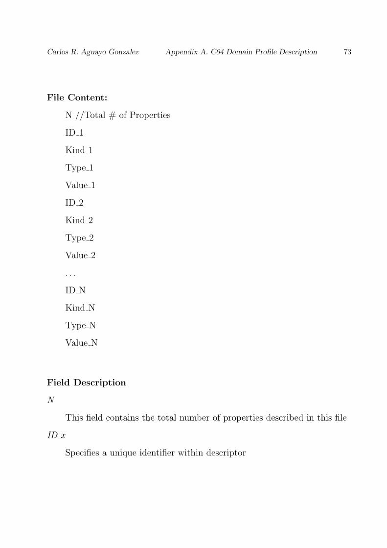
Carlos R. Aguayo Gonzalez Appendix A. C64 Domain Profile Description 73
File Content:
N //Total # of Properties
ID 1
Kind 1
Type 1
Value 1
ID 2
Kind 2
Type 2
Value 2
. . .
ID N
Kind N
Type N
Value N
Field Description
N
This field contains the total number of properties described in this file
ID x
Specifies a unique identifier within descriptor

Carlos R. Aguayo Gonzalez Appendix A. C64 Domain Profile Description 74
Kind x
The kind element’s kindtype attribute is used to specify the kind of prop-
erty.
Type x
The Type element is used to specify the value’s data type
Value x
The value element is used to provide a value setting to the properties
element.
Device Configuration Descriptor (DCD)
Filename DCD.xml - Filename DCD.c64
The intent of the DCD is to provide the means of describing the components
that are initially started on the CF DeviceManager node, how to obtain the
CF DomainManager object reference, connections of services to components
(CF Devices, CF DeviceManager), and the characteristics (file system names,
etc.) for a CF DeviceManager.
File Content
ID
Name
DomainManager
Number of Components
Filename Comp 1

Carlos R. Aguayo Gonzalez Appendix A. C64 Domain Profile Description 75
Filename Comp 2
. . .
Filename Comp N
Field Description
ID
The ID attribute is a unique identifier within the domain for the device
configuration. This id attribute is a UUID value.
Name
The name attribute is the user-friendly name for the CF DeviceMan-
ager’s label attribute.
DomainManager
The domainmanager element indicates how to obtain the CF Domain-
Manager object reference.
Number of Components
This element contains the total number of components that are started
up by the devicemanager
Filename Comp x
This element is used to reference a Software Package Descriptor which
describes deployment information for components that are started up on the
device.

Carlos R. Aguayo Gonzalez Appendix A. C64 Domain Profile Description 76
Software Assembly Controller (SAD)
Filename SAD.xml - Filename SAD.c64
The intent of the software assembly is to provide the means of describing the
assembled functional application and the interconnection characteristics of
the SCA components within that application. The component assembly pro-
vides four basic types of application information for Domain Management.
The first is partitioning information that indicates special requirements for
collocation of components, the second is the assembly controller for the soft-
ware assembly, the third is connection information for the various components
that make up the application assembly, and the fourth is the visible ports for
the application assembly.
File Content
ID
Name
AssemblyController
NumberOf Components
ID 1
SPD FileName 1
UsageName 1
NS/ResourceFactory
NSName 1/ResFactID 1

Carlos R. Aguayo Gonzalez Appendix A. C64 Domain Profile Description 77
. . .
ID N
SPD FileName N
UsageName N
NS/ResourceFactory
NSName N/ResFactID N
Number of Connections
ConnID 1
UsesID 1
UsesNS Name 1
FindBy/ProvidesPort?
ProvsNS Name 1
ProvsID 1*
Field Description
ID
The ID attribute is a DCE UUID which uniquely identifies the assembly.
Name
The name attribute is the user-friendly name for the CF Application-
Factory name attribute.
AssemblyController

Carlos R. Aguayo Gonzalez Appendix A. C64 Domain Profile Description 78
The assemblycontroller element indicates the component that is the main
CF Resource controller for the assembly
NumberOf Components
This field indicates the total number of SCA components which comprise
the assembly
ID X
The ID attribute is a DCE UUID that uniquely identifies the component.
It is the component name for the instantiation not the application name.
SPD FileName X
The componentfile element contains a reference to a SPD local file de-
scribing the component
UsageName X
The usagename element contains an applicable name for the component.
NS/ResourceFactory
This Field indicates the way to obtain the CORBA object reference for
the component instance. There are two possible kinds: ResourceFactory,
which indicates that the component has to be launched by a resource fac-
tory; or NS, which indicates that the component shall be located using the
naming service.
NSName X/ResFactID X
The contents of this field depend on the previous field. For NS; The
NSName is a partial name that is used by the CF ApplicationFactory to
form the complete context name. In the event of ResourceFactory, the Res-
Carlos R. Aguayo Gonzalez Appendix A. C64 Domain Profile Description 79
FactID X field refers to a particular CF ResourceFactory componentinstan-
tiation element found in the SAD
Number of Connections
This field indicates the total number of connections required by the ap-
plication
ConnID X
This field contains a user-friendly name to identify the connection
UsesID X
This field identifies the component port that is using the provided inter-
face from the providesport element.
UsesNS Name X
The namingservice element specifies a naming service name to search for
the desired component interface.
FindBy/ProvidesPort?
This field announces if the provides element of the connection is to be
found on the naming service or described by a ProvidesPort element
ProvsNS Name X
The NS Name element specifies a naming service name to search for the
desired component interface. ProvsID X* This field identifies the com-
ponent port that is providing the interface for the usesport element. (This
field is only included in the event that the provide end of the connection is
described by a ProvidesPort)

Carlos R. Aguayo Gonzalez Appendix A. C64 Domain Profile Description 80
Software Package Descriptor (SPD)
Filename SPD.xml -¿ Filename SPD.c64
The Software Package Descriptor is used at deployment time to load an SCA
compliant component and its various implementations.
File Content
ID
Name
PropertyFile
Descriptor
CodeType
FileName
EntryPoint
Field Description
ID
The ID field uniquely identifies the package and is a DCE UUID.
Name
The name attribute is a user-friendly label for the softpkg element.
PropertyFile
The propertyfile element is used to indicate the local filename of the
Property Descriptor file associated with the Software Package

Carlos R. Aguayo Gonzalez Appendix A. C64 Domain Profile Description 81
Descriptor
The descriptor element points to the local filename of the SCD file used
to document the interface information for the component being delivered to
the system.
CodeType
The codetype element will indicate the type of file being delivered to
the system. The valid values for the type attribute are: “Executable”, “Ker-
nelModule”, “SharedLibrary”, and “Driver”.
FileName
This field indicates the local filename of the code that is described by the
softpkg element, for a specific implementation of the software component.
EntryPoint
The entrypoint element provides the means for providing the name of
the entry point of the component being delivered.
Software Component Descriptor (SCD) Filename SCD.xml - File-
name SCD.c64 The Software Component Descriptor describes the ports and
interfaces of SCA components such as CF Resource, CF Device and CF Re-
sourceFactory.
File Content
componentType

Carlos R. Aguayo Gonzalez Appendix A. C64 Domain Profile Description 82
Field Description
componentType
The componenttype describes properties of the component. The com-
ponent types include resource, device, resourcefactory, domainmanager, log,
filesystem, filemanager, devicemanager, namingservice and eventservice.
Device Package Descriptor (DPD)
Not implemented
DomainManager Configuration Descriptor (DMD)
Filename DMD.xml -¿ Filename DMD.c64
File Content
ID
Name
SWPackage
Field Description
ID
The domainmanagerconfiguration element id attribute is a DCE UUID

Carlos R. Aguayo Gonzalez Appendix A. C64 Domain Profile Description 83
that uniquely identifies the DomainManager.
Name
The name field is the user-friendly name for the CF DomainManager
SWPackage
This element refers to the SPD for the CF DomainManager. This SPD
can be used to describe the CF DomainManager implementation and to spec-
ify the usesports for the services (Log(s), etc) used by the CF DomainManager

Vita
Carlos Roberto Aguayo Gonzalez was born on a sunny day in Ciudad Guz-
man, Jalisco. Mexico on Sept. 6th 1977. He received his B.S. from Instituto
Tecnologico y de Estudios Superiores de Monterrey (ITESM) in 2000. He was
employed by Mixbaal in Mexico from 2000 to 2002 as a Software Design En-
gineer. Subsequently, Carlos joined the Bradley Department of Electrical and
Computer Engineering at virginia Polytechnic Institute and State University.
After doing course work for two years, he joined the the Mobile and Portable
Radio Research Group (MPRG) of Virginia Tech as a Graduate Research
Assistant working for Dr. Jeff Reed. During his work at MPRG he has par-
ticipated in several projects implementing software defined radios (SDRs). He
is a member of the Open-Source SCA Implementation::Embedded (OSSIE)
development team. Currently, he is a Direct PhD candidate in Electrical
Engineering at the same University under the advise of Dr. Jeff Reed. His
research interests include efficient implementation of SDRs, cognitive radios,
and wireless networks.
84