DESIGN AND DEVELOPMENT OF AN FLC - BASED...
15
LPU-Laguna Journal of Engineering and Computer Studies Vol. 3 No.1 September 2015 55 DESIGN AND DEVELOPMENT OF AN FLC - BASED GROUND GRID INTEGRITY TESTING EQUIPMENT FOR SOTERO H. LAUREL (SHL) BLDG. OF LYCEUM OF THE PHILIPPINES UNIVERSITY – LAGUNA (LPU – L) Bryan M. Dimayuga 1 , Kevin Martin E. Jaron 1 , Alexander T. Montero 1 , Mark Kenneth Z. Peros 1 , Rionel B. Caldo 2 1 Undergraduate Students, Electrical Engineering Department 2 Faculty Member, Electronics and Computer Engineering Department Lyceum of the Philippines University-Laguna (LPU-L), Laguna, Philippines ABSTRACT This study provides a distinctive approach in assessing the integrity of a grounding system for it uses an advanced technique by constructing an equipment that is capable of determining the integrity of the grounding system of an institutional building. In this study, the proponents make use of the concepts of fuzzy logic in the assessment of the ground grid integrity test of LPU-L SHL bldg. It can be classify as Highly Acceptable (HA), Considerably Acceptable (CA), Just Acceptable (JA), Poor (P) and Critical (C). The input parameters include grounding conductor (conductivity), earth resistivity (Ω- o C) and grounding electrode (Ω -mm). The parameters in the model are acquired through the use of standards prescribed by the Philippine Electrical Code (PEC) and the Institute of Electrical and Electronics Engineering (IEEE). This study aims to provide a mathematical model to assess the integrity of the grounding system of the SHL bldg., design a fuzzy-based system, simulate and verify the effectiveness of the results. The proponents preferred to use the triangular membership functions and Sugeno-style of fuzzy inference systems. Keywords: fuzzy logic; ground grid integrity; Sugeno-style; Matlab Fuzzy Logic Toolbox. INTRODUCTION The effectiveness of Electrical system design and wiring of an institutional building depends on the reliability of its components. This includes proper functions of protective devices (such as fuses, circuit breakers and contactors for motors), proper insulation of conductors and also its grounding system. There are drawbacks and issues in electrical safety. This includes but not limited to electrical ground faults, short circuit currents, lightning and other transients often do occur in an institutional building. In this regard, issues of electrical safety when servicing electrical equipment has acquired growing importance. By establishing the new principles and methods of protection, taking into account advances in science and practice of electrical safety are only some of the ways to improve electrical safety conditions [1]. A properly designed, installed and maintained grounding system is very important for a safe and effective electrical system in an institution. The most important reason for effective grounding is to protect people. Second, is to include protection of structures and equipment for unintentional contact with energized lines. This also ensures the maximum safety for electrical system faults [1]. It is important to keep in mind that the requirements contained in the Institute of Electronics and Electrical Engineers (IEEE) codes or any codes that can be used as a standard for electrical system design constitute minimum electrical installation requirements.
Transcript of DESIGN AND DEVELOPMENT OF AN FLC - BASED...
LPU-Laguna Journal of Engineering and Computer Studies
Vol. 3 No.1 September 2015
55
DESIGN AND DEVELOPMENT OF AN FLC - BASED GROUND GRID INTEGRITY TESTING EQUIPMENT FOR SOTERO H. LAUREL (SHL) BLDG. OF LYCEUM OF
THE PHILIPPINES UNIVERSITY – LAGUNA (LPU – L) Bryan M. Dimayuga
1, Kevin Martin E. Jaron
1, Alexander T. Montero
1,
Mark Kenneth Z. Peros1, Rionel B. Caldo
2
1Undergraduate Students, Electrical Engineering Department
2Faculty Member, Electronics and Computer Engineering Department
Lyceum of the Philippines University-Laguna (LPU-L), Laguna, Philippines
ABSTRACT
This study provides a distinctive approach in assessing the integrity of a grounding system for it uses an advanced technique by constructing an equipment that is capable of determining the integrity of the grounding system of an institutional building. In this study, the proponents make use of the concepts of fuzzy logic in the assessment of the ground grid integrity test of LPU-L SHL bldg. It can be classify as Highly Acceptable (HA), Considerably Acceptable (CA), Just Acceptable (JA), Poor (P) and Critical (C). The input parameters include grounding conductor (conductivity), earth resistivity (Ω-
oC) and
grounding electrode (Ω -mm). The parameters in the model are acquired through the use of standards prescribed by the Philippine Electrical Code (PEC) and the Institute of Electrical and Electronics Engineering (IEEE). This study aims to provide a mathematical model to assess the integrity of the grounding system of the SHL bldg., design a fuzzy-based system, simulate and verify the effectiveness of the results. The proponents preferred to use the triangular membership functions and Sugeno-style of fuzzy inference systems.
Keywords: fuzzy logic; ground grid integrity; Sugeno-style; Matlab Fuzzy Logic Toolbox.
INTRODUCTION
The effectiveness of Electrical system
design and wiring of an institutional building
depends on the reliability of its components.
This includes proper functions of protective
devices (such as fuses, circuit breakers and
contactors for motors), proper insulation of
conductors and also its grounding system.
There are drawbacks and issues in electrical
safety. This includes but not limited to electrical
ground faults, short circuit currents, lightning
and other transients often do occur in an
institutional building. In this regard, issues of
electrical safety when servicing electrical
equipment has acquired growing importance.
By establishing the new principles and methods
of protection, taking into account advances in
science and practice of electrical safety are
only some of the ways to improve electrical
safety conditions [1].
A properly designed, installed and
maintained grounding system is very important
for a safe and effective electrical system in an
institution. The most important reason for
effective grounding is to protect people.
Second, is to include protection of structures
and equipment for unintentional contact with
energized lines. This also ensures the
maximum safety for electrical system faults [1].
It is important to keep in mind that the
requirements contained in the Institute of
Electronics and Electrical Engineers (IEEE)
codes or any codes that can be used as a
standard for electrical system design constitute
minimum electrical installation requirements.

LPU-Laguna Journal of Engineering and Computer Studies
Vol. 3 No.1 September 2015
56
These minimum requirements cannot ensure
that the equipment will perform satisfactorily.
For this reason, electrical practitioners often
require additional grounding components. One
of these consists of a copper conductor that is
directly connected to earth and installed in the
perimeter of the building. The steel building
columns and some non – current carrying
metallic frame of electrical equipment or some
electrical part of the system are connected to
this copper conductor to complete the
grounding system [2].
There are many factors in determining the
overall integrity of the grounding system. The
voltage drop, resistance and the continuity and
the earth resistance can significantly impact the
overall resistance of the grounding system. The
moisture content, mineral content, soil type, soil
contaminants and any other related factors
determine the overall resistivity of the earth. To
properly design a grounding system, the earth
resistivity must be measured and also must be
in a good condition to establish a low resistive
grounding [1].
The testing and evaluation of the integrity
of the grounding system to determine its actual
condition is the first step in the process to
correct problems. The study is focused on
creation of a new approach towards
establishing condition monitoring for grounding
integrity. Considerable benefits such as time
and labor reduction for the grounding devices
investigation with increase of accuracy of
failures location can be achieved by using this
proposed technique.
Lyceum of the Philippines University –
Laguna (LPU-L) itself consists of high voltage
apparatus, switchgear equipment and any other
equipment that involves electricity. It is
necessary to hand over normal and safe
operating condition to all people inside the
institution. In due course, it is important for
LPU-L to provide an effective and reliable
grounding system. One reason for increased
risk during electrical fault or short circuit
condition is due to ineffective integrity of the
grounding devices.
In this study, the proponents will use the
concepts and principles of fuzzy logic in
simulation of the ground grid integrity test. The
factors and parameters to be considered for
classifying the integrity of the grounding system
include the grounding conductor (conductivity),
earth resistance (Ω-oC) and the grounding
electrode (Ω -mm).
The parameters will be categorized as Very
Good (VG), Good (G), Satisfactory (S), Poor
(P) and Critical (C). The proponents will use
triangular membership functions for its input
and output parameters and it would employ the
Sugeno style of fuzzy inference system. The
proponents would verify the results using
Matlab Fuzzy Logic Toolbox and it will be
compared to derived formulas in Excel. This
study will be simulated purely mathematical.
Objectives of the Study
The prime objective of this study is to
design and develop an equipment that is
capable of determining the integrity of the
electrical grounding system of Lyceum of the

LPU-Laguna Journal of Engineering and Computer Studies
Vol. 3 No.1 September 2015
57
Philippines – Laguna, Sotero H. Laurel Culinary
Arts Building and clearly identifies the weak
points and discontinuities.
Specifically, this study aims to:
a) Understand the importance of a grounding
system and how it affects the electrical
system of an institutional building;
b) Design and develop an equipment that will
measure the grounding conductor
resistance, grounding electrode resistance
and earth resistance;
c) Asses using Fuzzy – Logic MatLab Toolbox
Kit that the installation and the parameters
of the grounding system will meet the basic
requirement of the National Electrical
Code, Philippine Electrical Code and IEEE
Code.
REVIEW OF RELATED LITERATURE
The proponents gathered several
references that provided them with different
ideas, thoughts and knowledge for developing
the ground grid integrity test. By these studies,
the proponents managed to come up with a
concrete knowledge of developing new ideas
that will contribute well to the study.
Table 2.1 Tabular Charts of Related Studies
LPU-Laguna Journal of Engineering and Computer Studies
Vol. 3 No.1 September 2015
58
Synthesis
Based on the review of related literature, it
can be summarized that ground grid integrity
test is vital in maintaining the effectiveness and
reliability of the grounding system. The
principles behind the operation of grounding
system and how it affects the overall
performance of an electrical system were
discussed. In order to maintain an effective
grounding system, an assessment of its
integrity should be done to ensure that it can
still operate properly especially upon the
occurrence of a fault or short circuit. Therefore,
testing and assessing the ground grid integrity
was made possible through several ways. This
can be seen above in which different
techniques was employed. Injecting AC inputs
were usually done in testing the integrity of the
grounding system. Technology has a big
impact in the modernization of ground grid
integrity testing methods. Advanced
electronics, programmable equipment and
computer simulation techniques became a
trend in today‟s era as they have more precise
measurements and results rather than the
usual methods which require much data inputs.
Table 2.1 below tabulates the comparison
of related literature on the basis of the following
parameters: a.) Description of the study, b.)
Hardware, c.) Software Used. D.) Test of
Method Used.
It can be seen that the test of the grounding
integrity is usually done in a substation. For this
reason, the proponents decided to conduct the
test in an institutional building since it is not yet
been established in a structure outside the
substation. In addition, the proponents will
design an equipment that will test the
grounding for the given research area using
point-to-point method. It is also proved that this
is the first time to test the integrity of the
grounding system of an institutional building.
Also, the proponents decided to use MatLab
Fuzzy Logic Toolbox Kit for the Assessment of
the integrity of the grounding system.
FUZZY RULE BASED SYSTEM
There are fuzzy rules constructed to
assess the integrity of the grounding system
such as Highly Acceptable (HA), Considerably
Acceptable (CA), Just Acceptable (JA), Poor
(P) and Critical (C).
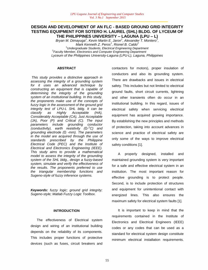
A hierarchical structure was constructed for
the simulation of the grounding system, Refer
to figure 3.1. The second level characterizes
the grounding conductor integrity, earth
resistance and the grounding electrode to
obtain an acceptable grounding system for
monitoring and surveillance purposes. The last
hierarchical level characterizes the integrity of
the grounding system. The following are the
sample rules stored at three different
hierarchical levels of structure:
If the Grounding Conductor Resistance
is<poor> and the Earth Resistance is<very
good> the Grounding Electrode Resistance
is<good>
Then the Ground Grid Integrity is<JA>
LPU-Laguna Journal of Engineering and Computer Studies
Vol. 3 No.1 September 2015
59
If the Grounding Conductor Resistance
is<good> and the Earth Resistance is<very
good> the Grounding Electrode Resistance
is<very good>
Then the Ground Grid Integrity is<CA>
If the Grounding Conductor Resistance
is<critical> and the Earth Resistance is<poor>
the Grounding Electrode Resistance is<good>
Then the Ground Grid Integrity is<P>
Grounding
Conductor
Resistance
Earth Resistance
Grounding
Electrode
Resistance
Highly
Acceptable
Considerably
Acceptable
Just
Acceptable
Poor
Critical
Decision
Figure 3.1 Hierarchical Structure for the
simulation of the integrity of the grounding
system.
The proponents have used the basic
process of designing the fuzzy logic for the
assessment of the integrity of the grounding
system as shown in Figure 2.2. The process
consists of five steps. For the first process
involving the formulation of the problem the
inputs to the fuzzy controller are the Grounding
Conductor Resistance, Earth Resistance and
the Grounding Electrode Resistance. The
variable is scored and sent to the ground grid
integrity assessment. The preceding step is by
selecting the fuzzy inference rule. This method
relies on by trial and error. The inference rule is
selected based on the degree of match. The
input values are averaged to fit linguistic terms.
The proponents used triangular function in
defining membership function. In this step
involves determining the position and the
shapes of the membership function as the
factors in determining the performance of the
fuzzy logic. The next is by performing fuzzy
inference based on inference method. In this
method the efficiency of the final control
surface is determined by the inference and
deffuzzification methods. Lastly is by selecting
a deffuzification method to assess the integrity
of the grounding system. In this case,
deffuzification is done by calculating the center
of gravity and the output is produced through
averaging technique.
In this study the proponents used Sugeno
style over Mamdami method because of only
those constant values will vary unlike in
Mamdami method the membership functions
will also varied. Therefore Mamdami method
will be more complicated than the Sugeno
Style.

LPU-Laguna Journal of Engineering and Computer Studies
Vol. 3 No.1 September 2015
60
FORMULATING THE PROBLEM AND
SELECTING THE INPUT AND OUTPUT
VARIABLES STATE.
SELECTING THE FUZZY INFERENCE
RULES.
DESIGNING FUZZY MEMBERSHIP
FUNCTIONS FOR EACH VARIABLE.
PERFORMING FUZZY INFERENCE
BASED ON INFERENCE METHOD.
SELECTING A DEFUZZIFICATION
METHOD TO ASSES THE INTEGRITY
OF THE GROUNDING SYSTEM
Figure 2.2 Design of Fuzzy Logic for the
Assessment of the Ground Grid Integrity
RESEARCH PROCESS
In chase of a successful upshot of this
study, developmental method was employed by
the proponents as their basis of their
procedures which predominantly intend to
achieve the set of objectives to solve the stated
problems. Aforementioned to the system‟s
advancement, this study also comprise of the
design of the system, where planning, problem
definition and setting up of the objectives were
involved.
The study also comprises of the testing and
valuation of the system as the proponents used
experimental method in testing the system‟s
operation. Set of experiments were conducted
to tabulate successful and abortive results. To
depict the system development life cycle, the
proponents have used flowcharts and block
diagrams to clearly understand the process.
The design of the entire system goes
behind the procedures below:
Figure 4.1 Research Process Block Diagram
Figure 4.1 shows the sequential process of
the system. It depicts the system‟s
developmental process which serves as a
guide by the proponents in putting up the
project.
Prototype Components
Power Inverter
Power inverter is an electrical device that
converts direct current (DC) to alternating

LPU-Laguna Journal of Engineering and Computer Studies
Vol. 3 No.1 September 2015
61
current (AC). The circuit main components
comprise of a 12V/12Ah dc source which will
serve as the main power source of the system,
two 2N3055 NPN transistors that act as the
switching part and connected in a push-pull
configuration which will generate a square
wave that will be fed in the step up transformer
to amplify the voltage.
Arduino Microcontroller
Arduino Microcontroller is an open-source
physical computing platform based on a simple
microcontroller board, and a development
environment for writing software for the board.
It will serve as the brain of the system for it
manipulates and executes the algorithm and
converts the measured analog input into its
equivalent digital output.
Voltage Divider Circuit
The voltage divider circuit will serve as the
circuit for measuring the resistance of the given
parameters using voltage divider theorem and
the equations below:
LED Display
Eq. 1
Eq. 2

LPU-Laguna Journal of Engineering and Computer Studies
Vol. 3 No.1 September 2015
62
The LED display will be the output indicator
of the system. The digital output coming from
the arduino microcontroller will be displayed
and viewed in the LED display.
MatLab Fuzzy Logic Toolbox
The linguistic variables are commonly used
instead of numerical variables in fuzzy logic
system. Fuzzification is the process of
converting a numerical variable (real number or
crisp variables) into a linguistic variable (fuzzy
number or fuzzy variable). The perception,
experience and the general knowledge of the
system behavior serve as the derivation that
will act as the control rules that relate the fuzzy
output to the fuzzy inputs. In this study, the
proponents make use of the averaging
technique in deriving its membership functions.
The rule table for the designed fuzzy logic
system for ground grid integrity assessment is
given in Table 3.1
Table 4.1Fuzzy Associative Memory (FAM) Matrix for Ground Grid Integrity
Assessment
From the combination of the input
parameters such as grounding conductor, earth
resistance and grounding electrode, 125 fuzzy
rule bases were able to formulate. The
triangular figures of the associated function of
this arrangement presume that for any
particular input there is only one dominant
fuzzy subset. The linguistic variables are
converted into a numerical variable.
Creating, editing and observing the fuzzy
inference system makes use of five primary
Graphical User Interfaces (GUIs). It comprise of
Fuzzy Inference System (FIS) Editor,
Membership Function Editor, Rule Editor, Rule
Viewer and Surface Viewer. If changes were
made to the FIS of one of the toolbox, the effect
can be seen in other GUIs since it is
dynamically connected with each other. In
addition to these five primary GUIs, the toolbox
includes the graphical ANFIS Editor GUI, which
is used for building and analyzing Sugeno-
types adaptive neural fuzzy inference systems
[3].
The method used in this study for Matlab
Fuzzy Logic Toolbox simulation is the Sugeno
or Takagi-Sugeno-Kang of fuzzy inference that
was introduced in 1985 and it is similar to
Mamdani method in many respects. The first
two parts of the fuzzy inference process,
fuzzifying the inputs and applying the fuzzy
operator are exactly the same. Sugeno output
membership functions are either linear or
constant unlike the Mamdami. In this paper, the
proponents think about the use of constants as
output membership functions [3].

LPU-Laguna Journal of Engineering and Computer Studies
Vol. 3 No.1 September 2015
63
EXPERIMENTS AND ANALYSIS OF
RESULTS
The experimentation was done
methodically as discussed in the block diagram
in the previous chapter (Figure 4.1). The results
obtained from the experimentation will prove
the system‟s effectiveness and consistency.
Earth Resistance Measurement
The earth resistance of a single spike, of
diameter and length buried to earth with a soil
resistivity can be calculated as follows:
Where: Soil resistivity of the soil in ohm –
meter (Ωm)
L Buried length of the rod in meter (m)
d diameter of the rod in meter (m)
The proponents conducted a parallel test of
measuring earth resistance by using a 10
centimeter (0.1 meter) in length, 3.5 square
millimeters (2.11x10⁻³
meter in diameter)
copper rod supposing that the rod is the actual
grounding rod buried.
Table 5.1 Tabulated Results
Figure 5.1 Graphical Representations of
Results
Grounding Conductor and Electrode
Measurement
The value of the grounding conductor
resistance can be obtained using the formula
formulated George Simon Ohm known as the
Laws of Resistance:
Where: Conductor resistivity in ohm – meter
(Ωm)
L Length of the conductor in meter (m)
A Area of the conductor in square meter
(m2)
The proponents made a computation
parallel for the test procedure conducted to
measure the resistance of the grounding
conductor to prove and to assure the accuracy
of the equipment for the measurement of the
grounding conductor resistance using a 3 meter
copper conductor with a 5.18868 x 10⁻⁷
m2
area.
Eq. 4
Eq. 3
Eq. 5
LPU-Laguna Journal of Engineering and Computer Studies
Vol. 3 No.1 September 2015
64
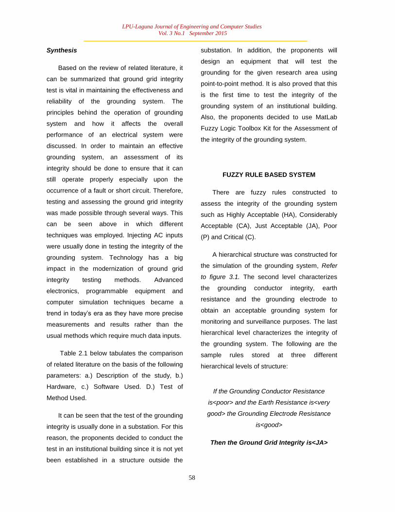
In addition to test the accuracy of the
equipment, the proponents also conducted a
test using a carbon type resistor with a value of
150 ohms ±5% tolerance.
Table 5.2 Tabulated Results
Figure 5.2 Graphical Representation of
Results
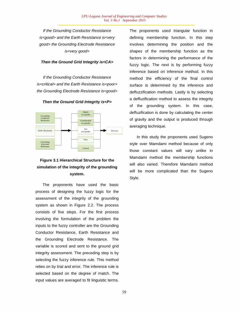
Table 5.3 Tabulated Results
Figure 5.3 Graphical Representation of
Results
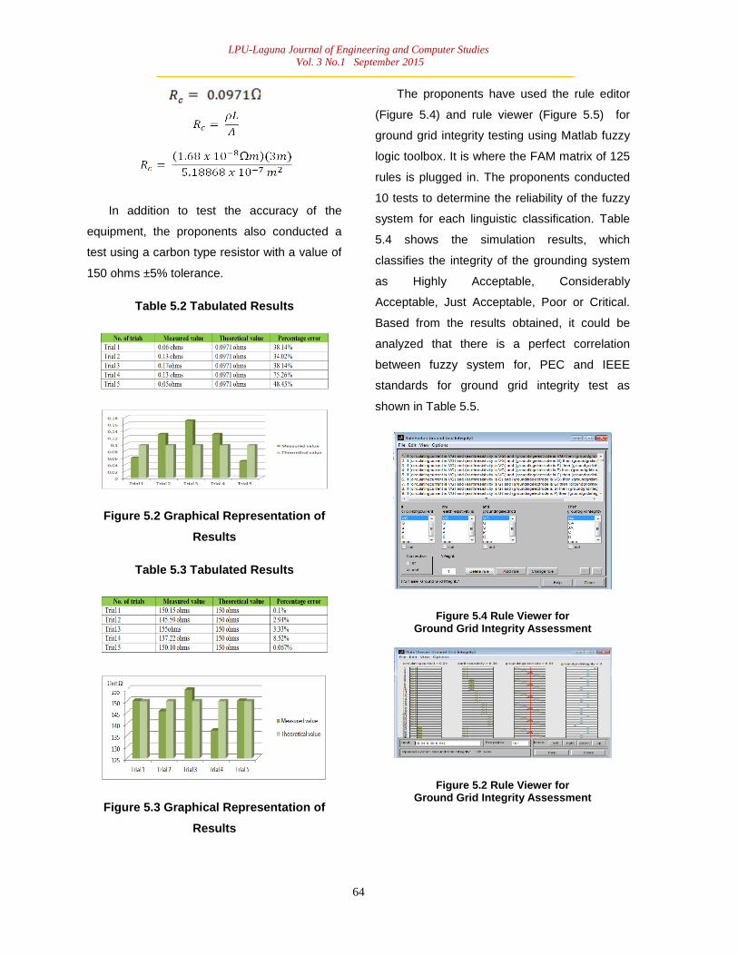
The proponents have used the rule editor
(Figure 5.4) and rule viewer (Figure 5.5) for
ground grid integrity testing using Matlab fuzzy
logic toolbox. It is where the FAM matrix of 125
rules is plugged in. The proponents conducted
10 tests to determine the reliability of the fuzzy
system for each linguistic classification. Table
5.4 shows the simulation results, which
classifies the integrity of the grounding system
as Highly Acceptable, Considerably
Acceptable, Just Acceptable, Poor or Critical.
Based from the results obtained, it could be
analyzed that there is a perfect correlation
between fuzzy system for, PEC and IEEE
standards for ground grid integrity test as
shown in Table 5.5.
Figure 5.4 Rule Viewer for Ground Grid Integrity Assessment
Figure 5.2 Rule Viewer for Ground Grid Integrity Assessment

LPU-Laguna Journal of Engineering and Computer Studies
Vol. 3 No.1 September 2015
65
Table 5.4Testing Results usingMatLab Fuzzy Logic Toolbox
Table 5.5 Verification of Fuzzy based results with PEC/IEEE Standards
CONCLUSION
The contribution of this study is a tangible
procedure in determining the effectiveness of
the integrity of the grounding system.
Developed in this thesis is an FLC based
equipment that is capable of determining the
integrity of the grounding system of LPU-L SHL
bldg. The proponents had developed the
ground grid integrity testing equipment by
injecting a substantial amount of direct current
into the grounding system and measuring its
important parameters. The equipment has the
capability to assess and classify the condition
of the grounding system and if it can still
operate properly in normal and anomalous
conditions especially upon the occurrence of a
fault.
The assessment of the grounding system
was done through the use of the concepts of
fuzzy logic. Averaging technique was employed
in deriving its membership functions. From the
combination of the input parameters such as
grounding conductor resistance, earth
resistance and grounding electrode resistance,
125 fuzzy rule bases were able to
formulate.The triangular figures of the
associated function of this arrangement
presume that for any particular input there is
only one dominant fuzzy subset. The linguistic
variables are converted into a numerical
variable. The proponents think about the use of
constants as output membership functions.
It has been verified experimentally from
theoretical studies and actual data analysis as
supported by the data above to prove the
effectiveness of the results. It can be seen that
ground grid integrity test is working as it should
be, considering that it established a perfect
correlation between theoretical and the actual
values that had been obtained.
The proponents were able to establish a
distinctive approach towards the
unsophisticated way of assessing the integrity
of the grounding system that will present a
cheaper and quicker method which will also

LPU-Laguna Journal of Engineering and Computer Studies
Vol. 3 No.1 September 2015
66
apply most likely to the improvement and
development of maintaining an effective and
reliable grounding system.
REFERENCES
[1] W. Keith Switzer, “Practical Guide to
Electrical Grounding,” ERICO, Inc., 1999
[2] Truman C. Surbrook and Jonathan R.
Althouse, “Interpreting the National
Electrical Code 8th
Edition”, 2008.
[3] Rionel B. Caldo, “Fuzzy Logic Derivation
and Simulation of a Three-Variable Solar
Water Heater Using Matlab Fuzzy Logic
Toolbox,” Proceedings of the November
2013 IEEE International Conference.
[4] Allan H. Robbins and Wilhelm C. Miller,
“Circuit Analysis: Theory and Practice, 3rd
edition”, Thomson/Delmar Learning, 2003.
[5] Philippine Electrical Code, Institute of
Integrated Electrical Engineers of the
Philippines, 2009.
[6] 81 – 2012 – IEEE Guide for Measuring
Earth Resistivity, Ground Impedance, and
Earth Surface Potentials of a Grounding
System.
[7] [Online].
http://en.wikipedia.org/wiki/Copper_loss
[Accessed: August 1, 2014].
[8] B.L. Theraja and A.K. Theraja, “ABC of
Electrical Engineering”, S.Chand and
Company LTD., 2012.
[9] [Online].
http://ecmweb.com/content/achieving-
acceptable-ground-poor-soil [Accessed:
August 1, 2014].

LPU-Laguna Journal of Engineering and Computer Studies
Vol. 3 No.1 September 2015
67
FUZZY LOGIC ALGORITHM CONSTRUCTION
Figure 9.1Making a Sugeno file.
STEP 1:
Specify, create FIS editor by specifying the
fuzzy inference system (mamdani or sugeno
style) and save it as “Ground Grid Integrity”.
(See Figure 9.1)
Figure 9.2Adding variables for input twice.
STEP 2:
Go to edit, add variable (Input) two (2) times.
(See Figure 9.2)
Figure 9.3Naming the inputs “groundingconductor”, “earthresistivity”
and “groundingelectrodes”.
STEP 3:
Change input1, input2 and input3 to
“groundingconductor”, “earthresistivity” and
“groundingelectrodes” respectively. (See Figure
9.3)
Figure 9.4 Naming the output “groundgridintegrity”.
STEP 4:
Change the output1 and named it to
“groundgridintegty”. (See Figure 9.4)
Figure 9.5 Different functions display namely mf1, mf2 and mf3.
STEP 5:
Double click the “groundingconductor” in the
input and you will see different membership
functions namely mf1, mf2 and mf3. (See
Figure 9.5)

LPU-Laguna Journal of Engineering and Computer Studies
Vol. 3 No.1 September 2015
68
Figure 9.6Additional of 5 MF’s.
STEP 6:
Go to edit, add MFs, choose 2 and click ok to
have 5 MF‟s. (See Figure 9.6)
Figure 9.7 Changing mf1 to its specific parameters.
STEP 7:
Go to mf1 and specify the parameters [-0.01
0.15 0.21], change the name of mf1 to “VG”
(Very Good). (See Figure 9.7)
Figure 9.8 Changing mf2 to its specific parameters.parameters.
STEP 8:
Go to mf2 and specify the parameters [0.2 0.35
0.41], change the name of mf2 to “G” (Good).
(See Figure 9.8)
Figure 9.9: Changing mf3 to its specific parameters.parameters.parameters.
STEP 9:
Go to mf3 and specify the parameters [0.4 0.55
0.61], change the name of mf3 to “S”
(Satisfactory). (See Figure 9.9)
Figure 9.10Changing mf4 to its specific parameters.
STEP 10:
Go to mf4 and specify the parameters [0.6 0.75
0.81], change the name of mf4 to “P” (Poor).
(See Figure 9.10)

LPU-Laguna Journal of Engineering and Computer Studies
Vol. 3 No.1 September 2015
69
Figure 9.11Changing mf5 to its specific parameters.
STEP 11:
Go to mf5 and specify the parameters [0.8 0.95
1.01], change the name of mf5 to “C” (Critical).
(See Figure 9.11)
Figure 9.12Changing “earthresistivity” specifications and parameters.
STEP 12:
Click the “earthresistivity” and repeat the
process from STEP 6 to STEP 11. (See Figure
9.12)
Figure 9.13Changing “groundingelectrodes” specifications and parameters.
STEP 13:
Click the “groundingelectrodes” and repeat the
process from STEP 6 to STEP 11. (See Figure
9.13)
Figure 9.14Additional for MFs for 5 MFs Output.
STEP 14:
Click the “groundgridintegrity”, click edit then
add MFs then choose 2 and click OK. (See
Figure 9.14)
Figure 9.15Changing the Names and Parameters.
STEP 15:
Change the name of mf1, mf2, mf3, mf4 and
mf5 to “HA”(Highly Acceptable),
“CA”(Considerably Acceptable), “JA”(Just
Acceptable), “P”(Poor) and “C”(Critical)
respectively and change also the parameters
from mf1, mf2, mf3, mf4 and mf5 to “5”, “4”, “3”,
“2” and “1” respectively. (See Figure 9.15)