
Design and development of a freeform active mirror for an ...
11
Design and development of a freeform active mirror for an astronomy application Zalpha Challita Tibor Agócs Emmanuel Hugot Attila Jaskó Gabby Kroes William Taylor Chris Miller Hermine Schnetler Lars Venema Laszlo Mosoni David Le Mignant Marc Ferrari Jean-Gabriel Cuby
Transcript of Design and development of a freeform active mirror for an ...

Design and development of a freeformactive mirror for an astronomyapplication
Zalpha ChallitaTibor AgócsEmmanuel HugotAttila JaskóGabby KroesWilliam TaylorChris MillerHermine SchnetlerLars VenemaLaszlo MosoniDavid Le MignantMarc FerrariJean-Gabriel Cuby

Design and development of a freeform active mirrorfor an astronomy application
Zalpha Challita,a,* Tibor Agócs,b Emmanuel Hugot,a Attila Jaskó,c Gabby Kroes,b William Taylor,d Chris Miller,d
Hermine Schnetler,d Lars Venema,e Laszlo Mosoni,c David Le Mignant,a Marc Ferrari,a and Jean-Gabriel Cubya
aAix Marseille Université, CNRS, LAM (Laboratoire d’Astrophysique de Marseille) UMR 7326, 13388, Marseille, FrancebNOVA Optical Infrared Instrumentation Group at ASTRON, P.O. Box 2, 7990 AA Dwingeloo, The NetherlandscKonkoly Thege Miklós Astronomical Institute (MTA Research Centre for Astronomy and Earth Sciences), 1525, PO Box 67, Budapest, HungarydAstronomy Technology Centre (UK-ATC), Blackford Hill, Edinburgh, EH9 3HJ, ScotlandeASTRON, P.O. Box 2, 7990 AA Dwingeloo, The Netherlands
Abstract. The advent of extremely large telescopes will bring unprecedented light-collecting power and spatialresolution, but it will also lead to a significant increase in the size and complexity of focal-plane instruments. Theuse of freeform mirrors could drastically reduce the number of components in optical systems. Currently, manu-facturing issues limit the common use of freeform mirrors at short wavelengths. This article outlines the use offreeform mirrors in astronomical instruments with a description of two efficient freeform optical systems. A newmanufacturing method is presented which seeks to overcome the manufacturing issues through hydroforming ofthin polished substrates. A specific design of an active array is detailed, which will compensate for residualmanufacturing errors, thermoelastic deformation, and gravity-induced errors during observations. The combinedhydroformed mirror and the active array comprise the Freeform Active Mirror Experiment, which will produce anaccurate, compact, and stable freeform optics dedicated to visible and near-infrared observations. © 2014 Society ofPhoto-Optical Instrumentation Engineers (SPIE) [DOI: 10.1117/1.OE.53.3.031311]
Keywords: freeform mirrors; active optics; optical design and manufacturing; deformable mirrors; actuators; system architecture.
Paper 131007SSP received Jul. 2, 2013; revised manuscript received Nov. 19, 2013; accepted for publication Dec. 2, 2013; publishedonline Jan. 9, 2014.
1 Freeform and Active OpticsFreeform optics has the potential to drastically reduce thecomplexity of optical instruments. Several definitions of“freeform optics” can be found in the literature with themost common being that the shape of a freeform opticsmust be nonaxisymmetric.1 It is a rather loose definition;mathematically, since an off-axis conical section could bedescribed as a nonaxisymmetric optics, as was demonstratedby Lubliner and Nelson2 as far back as 1980. Likewise, adap-tive and active optics have been used for many years to createnonaxisymmetric optics through the addition of aberrationsto the classical optical profiles. For freeform optics, the realdifference and originality lie in the extreme deviation fromthe best-fit sphere, which can be as large as a millimeter. Aswill be discussed, such extreme shapes require differentmanufacturing techniques compared with those of producingclassical optical components.
There are numerous technological benefits associatedwith freeform optics: a reduction of overall instrumentmass and volume, an improvement in reliability and opera-tional availability, and an increased throughput.3,4 Many ofthese advantages would be especially evident in futureextremely large telescopes, which look set to house some ofthe largest instruments yet built.5–7 However, despite theseadvantages, the implementation of freeform optics is cur-rently held back by the difficulty of manufacturing highlyaspherical optical surfaces that are of sufficient quality toallow visible imaging.
In this article, we present the concept of FAME, theFreeform Active Mirrors Experiment, and report the current
status and direction of the project. The goal of FAME is toproduce a freeform mirror whose extreme aspherical shapeis actively controlled by a dedicated array of actuators. Theoptical surface or “face-sheet” will be manufactured throughhydroforming a prepolished thin mirror. However, this proc-ess, which exploits the plastic behavior of ductile materials,will not yield a perfect freeform mirror. While the high-orderoptical quality of the mirror will be secured by the prepolish-ing of the face-sheet, the low- and mid-order shape errorswill be corrected by an active array using techniques notdissimilar to active optics.8–10
Through the use of active optics techniques, FAME aimsto relax both the requirements on the face-sheet manufactur-ing and that of the optical alignment. The acceptable errorson the face-sheet can be defined in terms of spatial frequen-cies instead of amplitude. Considering an array of N2 actua-tors, the system allows the correction of spatial frequenciesup to N∕2 cycles per pupil. The amplitude of required cor-rections is quantified by finite element analysis (FEA), whichallows constraints to be placed on the required force andstroke of the actuators. Within a predefined limited range,the active array can adapt its shape to optimize or adjustthe mirror’s performance. In addition, the system will incor-porate a metrology system that measures the performance ofthe optical train and calculates the required changes on theindividual actuators.
The work presented in this article reports on the currentstatus of various aspects of this ongoing project. It beginswith a comparison of classical designs to those which includefreeform optics. It then details the FEA of the hydroforming
*Address all correspondence to: Zalpha Challita, E-mail: [email protected] 0091-3286/2014/$25.00 © 2014 SPIE
Optical Engineering 031311-1 March 2014 • Vol. 53(3)
Optical Engineering 53(3), 031311 (March 2014)

method and presents the results of the prototyping of thefreeform face-sheet and the active array with preliminaryanalysis of the manufacturing method’s performance.Finally, a discussion on the required control/commandstrategies is presented.
2 Optimizing Active Freeform-Based OpticalDesigns
2.1 Method
Optical designs that make use of freeform mirrors are becom-ing more common. In illumination systems, freeform opticshas been used for some time. However, for more complexproblems, where it is necessary to form images, new designtools are required. One such tool is the simultaneous multiplesurfaces modeler. Nodal-aberration theory11 and other theo-ries regarding nonaxially symmetric systems are also valu-able and have facilitated different design methods. Severalpolynomial families have been developed to mathematicallyrepresent the freeform surface such as the Bernstein,12 theForbes,13 or the φ-polynomials.1 These polynomials providemore freedom to describe the surfaces compared with that ofthe standard Zernike polynomials.
Usually, the performance metric used in the optimizationprocess of an optical system is based on better image quality,faster F-ratio, larger field-of-view (FoV), or a combinationof these. A limited space envelope or accessibility require-ments are strong drives to use more complex optical surfaces,although freeform optical components generally delivera system with superior characteristics.
The improvement of a system can only be made effi-ciently when the coupling between the different degreesof freedom (DOFs) of a system and the effect on the perfor-mance metric is well understood. For freeform optics, theDOF (the configuration vector) increases and results ina more complex optimization algorithm.
The correlation between the configuration vector andthe performance metric can be written as m ¼ fðxÞ,where m is the performance metric, x is the configurationvector, and f is a function that defines the relationship.We intend to find the best x to minimize m. Typically,there is a maximum allowable value for m, correspondingto the requirements of the system. Usually the functionfðxÞ is nonlinear, and there are interdependencies betweenthe configuration parameters, which result in an ill-definedoptimization problem. We developed the method describedin Fig. 1 to overcome these difficulties and to minimize them.The key steps in the method are as follows:
• Singular value decomposition (SVD)-based subsetselection14,15 through the SVD of the sensitivity matrix(the change in performance by small variations in theconfiguration vector). This reduced the set of optimi-zation parameters, which is then used to optimize thedesign.
• We used Newton’s method based on SVD and the stan-dard optimization methods of Zemax® that are basedon damped least squares and orthogonal descent tooptimize the design and as such to minimize the per-formance metric.
As usual, the optical design process aims to find theglobal minimum of the solution space and tries to avoid
the local minima or divergence. The optical design methodpresented above optimizes the solution using the mostsensitive configuration vector subset. Essentially, the optimi-zation method intends to smooth out the surface of theperformance metric by changing—in each optimizationcycle—the variables of the system based on their currentinfluence on the performance metric.
2.2 Comparing Freeform and Classical OpticalDesigns
In the following section, we present optical designs usingextreme freeform surfaces. The main aim of the optimizationprocess is to design an optical system that shows an improve-ment in some of the characteristics compared with the initial(classical) design. Also, more importantly, the design shallconsist of only one extreme freeform surface, and the restof the optical components have to be spherical or at leastshould be easy to manufacture and test. This configura-tion has a huge benefit in that the optical system itselfcan be used as the test-bed for the freeform surface, sincethe spherical surfaces can be manufactured and aligned withhigh accuracy.
In this section, we describe the design of two optical sys-tems making use of freeform surfaces: a modified Three-Mirror Anastigmat (TMA) and a very wide-field and fastF-ratio two-mirror imaging system. We kept the sameentrance pupil and the F-ratio during the reoptimization forease of comparison while using the root mean-squared(RMS) spot radius as the performance metric. The aim ofusing freeform surfaces was to improve the optical perfor-mance and also to increase the FoV. The designs areshown in Fig. 2.
For the first freeform system, the starting point is a TMAthat resembles the Cook design and has an 8 deg × 8 deg
Fig. 1 Optical design methodology used in the design of freeformoptical components.
Optical Engineering 031311-2 March 2014 • Vol. 53(3)
Challita et al.: Design and development of a freeform active mirror for an astronomy application

FoV. The primary mirror proved to be the best candidate fora more complex surface with higher DOF.
During the optimization process, it became apparent thatthe best performance can be achieved with a design that hasthe stop located close to the secondary mirror. It was possibleto increase the FoV to 8 deg × 12 deg with an image qual-ity that is better than the starting-point design.
The second optical design is a very wide-field two-mirrorcamera which would be suitable for large surveys with min-imal observation time due to the high transmission. Thisoptical design better suits a possible prototype, since it isa relatively simple system with only two components andis therefore easier to align. An off-axis Schwarzschild opticalsystem was the starting point of the optimization with anentrance pupil of 50 mm, a FoV of 10 deg×10 deg andan F-ratio of 4. The end-point design had a convex primaryfreeform mirror with a diameter of 100 mm. It is an off-axisasphere with the addition of Zernike polynomials (which cor-responds to a freeform shape or φ-polynomials definition),and the second mirror is an ellipsoid with minor asphericity.Compared with the initial (classical) design, image quality
improved significantly: the RMS spot radius of the designis improved by almost 40%.
In Fig. 3, both the sag and the deviation from the bestfit sphere (BFS) for the primary mirrors are shown. Forthe TMA, in the case of the end-point design, it can beseen that the primary mirror has a 1.8-mm departure fromBFS, so it is an extremely difficult surface to manufacturewith conventional methods.
3 Hydroforming Freeform ShapesManufacturing freeform mirrors that satisfy the requirementsfor visible and infrared observations are a real challenge. Asdescribed by Fuerschbach et al.1 in 2011, these componentsare more suited for thermal infrared (LWIR band) observa-tions. Based on the preliminary specifications of the twooptical designs described in the previous section, the FAMEmanufacturing method aims to deliver the required opticalperformance, while also keeping the manufacturing costslow. Nevertheless, the development of a brand new methodraises several issues that need to be addressed in detail.
Fig. 2 (a) Layout of a F4 Three-Mirror Anastigmat (TMA) design that resembles the Cook design with thefreeform primary, spherical secondary, and tertiary. It has a field-of-view (FoV) of 8 deg×12 deg (theinitial design with three conical sections provides 8 deg×8 deg FoV). (b) Layout of the freeform basedtwo-mirror system (10 deg×10 deg).
Fig. 3 Deviation from best fit sphere (BFS). (a) Primary mirror of the F4 TMA design. (b) Primary mirror ofthe two-mirror design. In the first case, the mirror is an extreme freeform with 1.8-mm deviation from theBFS. (Units on both figures are in mm.)
Optical Engineering 031311-3 March 2014 • Vol. 53(3)
Challita et al.: Design and development of a freeform active mirror for an astronomy application

3.1 Plasticizing of Metallic Materials
The hydroforming method obtains freeform shapes throughdeformation of flat or spherical thin metallic mirrors. Suchsubstrates have principally been used for the aluminumdishes required for radio-astronomy applications.16 Thehydroforming method is illustrated in Fig. 4. The prepolishedsubstrate is held at its edges on a mold with a specific profile,and then a large amount of pressure is applied by a fluiduntil the substrate is formed into the shape of the mold.The resulting substrate keeps a permanent deformation afterthe removal of the pressure, as the material enters the plasticdomain of ductile materials. This technique avoids any hardcontact between the optical surface and the mold, meaningthat the small local errors of the mold do not degrade thepolished optical surface. This process only imparts the low-spatial frequency deformations, whereas any high-spatial fre-quency errors are not imprinted on the mirror’s surface—akey advantage of hydroforming. The final expected residualerrors are only form errors that could be compensated for byan active array with a reasonable number of actuators.
Several metallic materials can be selected based on crucialparameters such as polishing ability, stability over time, elas-tic limit, and plastic domain. Based on our experience inthe field of metallic mirrors, we selected stainless steel(AISI420), aluminum (Al 6061-T6), and titanium (TA6V,T40) as candidates for prototyping and while developingthe manufacturing process. The development method wasimplemented in three steps: finite element predictions, pro-totyping, and comparison.
3.2 Modeling Methods and Study Cases
The FEA provides good approximations of the plastic behav-ior of the substrate, but the predictions are limited byunknowns such as: the history of the material, residualstresses, the initial and the final geometries of the substrate,work hardening, and anisotropic microstructure. The FEAresults highlighted two possible issues: springback effectand the degradation of the surface. Having the ability to com-pare the predicted performance (from the model) with realtests is important to allow us to fine tune the model.
The polished substrate is defined by three functionalzones, as is shown in Fig. 4: the edge zone to hold the mirrorin place, the flange zone where plasticization will occur, and
the optical zone. A homogeneous controlled pressure isapplied on the optical zone, whereas a clamping pressureis applied on the edge zone. These conditions are optimizedusing FEA.
As described in Fig. 5, two different approaches can bechosen to extract the working parameters of the hydroform-ing process from the FEA. We define zðrÞ as the sag, r as themirror radial coordinate, RC as the radius of curvature, andBFS as the best fit sphere. The first method uses a simplespherical mold with which both spherical and aspherical mir-rors can be made. The final shape depends on the materialparameters, the mold aperture, the substrate geometry, andthe pressures applied.
The second method uses a mold whose shape is opti-mized, while the rest of the parameters are fixed. The initialshape of this second mold corresponds to the final freeformshape and is iteratively modified to take into account thespringback effect.17
The FEA is performed in order to start a parametric analy-sis and to extract two relevant cases for the study usingmethod one. The face-sheets are modeled with quadrangleelements that allow a fine meshing of the mirrors section. 18
The analysis is truly nonlinear including large displacements,elastic-plastic behavior, and contact analysis. The materialused for this parametric analysis is stainless steel (X30Cr13or AISI420b) that can be polished. About 15,000 elementsare used, giving a sampling of 1000 points on the opticalsurface for the optical quality extraction.
Figure 6 summarizes the results obtained in terms of RMSand peak-to-valley (PV) deviations from the BFS. Moderateasphericity (about 300 μm) is evident on the 2-mm mirrorwhen a spherical F∕0.5 mold is used. The inverse case ishighlighted with an F∕2 mold and a 1-mm thick substrate:the resulting plasticized mirror remains spherical butpresents a larger aperture (see also pictures in Fig. 7). Atthe end of the process, we expect to obtain a spherical mirrorwith an error of less than 2-μm RMS. Table 1 describes theworking parameters and the optical quality obtained for thesetwo particular cases.
3.3 Substrates Realization and Hydroforming Engine
The manufacturing process can be described in four mainsteps: machining of substrates, polishing, hydroforming,
Fig. 4 Substrate and mold functional aspects.
Optical Engineering 031311-4 March 2014 • Vol. 53(3)
Challita et al.: Design and development of a freeform active mirror for an astronomy application

and finishing. Several issues appear at each step of the proc-ess such as the anisotropy of the substrates, the introductionof surface stress during the machining phase and their relax-ation during the polishing phase, the bending of the face-sheets on the polishing supports, the bending on the testsupports, and the degradation of the roughness due to plasticdeformation of the surface. All these issues were overcomeduring the prototyping phase.
3.3.1 Machining and polishing of substrates
The method chosen to manufacture the initial substratesresults from a compromise between: minimizing materialanisotropy, minimizing stress induced during machining,reaching of high-mechanical planarity, and parallelism onthin and large substrate diameters. These aspects are impor-tant to improve the homogeneity of the material microstruc-ture and to reduce the noncontrolled deformations of the
Fig. 5 Two different optimization methods used to extract the working parameters.
Fig. 6 (a) For different mold apertures, evolution of the root mean-squared (RMS) and peak-to-valley(PV) deviations from the BFS, considering mirror thicknesses between 0.5 and 3 mm (100-mm opticaldiameter AISI420b mirror). (b) Redistribution of equivalent Von Mises stresses after the formation of a 2-mm substrate on F∕0.5 spherical mold aperture, illustrating the springback effect.
Optical Engineering 031311-5 March 2014 • Vol. 53(3)
Challita et al.: Design and development of a freeform active mirror for an astronomy application

piece due to stress relaxations. Obtaining thin and largediameter substrates on metallic materials of a high-mechani-cal quality was an issue tackled by a process using electricaldischarge machining and double-sided surface grinding.
The substrates were machined from a round bar ofAISI420b stainless steel. They present a total diameter of140 mm and a thickness of approximately 1 and 2 mmwith the following mechanical quality: flatness better than30 μm RMS, a wedge lower than 20 μm RMS, and a1.6 μm RMS roughness. A specific thermal treatment byannealing was also performed to relax residual stresses com-ing from machining and to ensure a stabilized mechanicalbehavior during polishing.
The polishing step is made easier as it is performed beforethe forming step, meaning it is reduced to a flat polishing.However, the polishing of high-aspect ratio metallic materialsat optical level remains a difficult task. The polishing pro-cedure developed at LAM, based on traditional full-sized toolpolishing, allowed a flatness of 3 μm PV to be reached and a5 nm RMS roughness. A flat polished mirror is illustrated onFig. 8. The same mirror after hydroforming is also illustrated.
3.3.2 Hydroforming engine
Figure 9 presents the design of the hydroforming prototype.The flat polished mirror is integrated between the mold and
Fig. 7 (a) Starting with a 1-mm thickness substrate on a spherical mold opened at F∕2, the plasticizedmirror remains spherical. (b) Starting with a 2-mm thickness substrate on a spherical mold opened atF∕0.5, the plasticized mirror becomes aspherical with a departure from the BFS of 280 μm PV.
Fig. 8 (a) 2-mm thickness mirror flat polished in AISI420b stainless steel. (b) The same mirrorhydroformed.
Table 1 Parameters of the two study cases. From a spherical mold,either spherical or aspherical mirror can be achieved.
Study case Spherical Aspherical
Working parameters
Material X30Cr13 X30Cr13
Total disk diameter (mm) 140 140
Optical diameter (mm) 100 100
Disk thickness 1 mm,constant
2 mm,constant
F∕ mold F∕2 F∕0.5
Forming pressure (MPa) 15 45
Clamping pressure (MPa) 10 10
Optical quality obtained by modeling
Error/departure from BFS PV (μm) 1.8 280
RMS (μm) 0.38 66
F∕D 10.7 0.54
Optical Engineering 031311-6 March 2014 • Vol. 53(3)
Challita et al.: Design and development of a freeform active mirror for an astronomy application
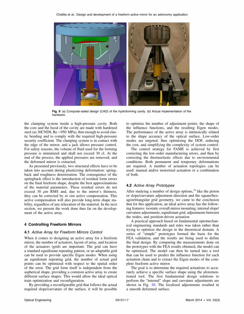
the clamping system inside a high-pressure cavity. Boththe core and the hood of the cavity are made with hardenedsteel (as 30CND8, Re ∼950 MPa), thin enough to avoid elas-tic bending and to comply with the required high-pressuresecurity coefficient. The clamping system is in contact withthe edge of the mirror, and a jack allows pressure control.For safety reasons, the volume of fluid used for the formingpressure is minimized and shall not exceed 30 cl. At theend of the process, the applied pressures are removed, andthe deformed mirror is extracted.
As presented previously, two structural effects have to betaken into account during plasticizing deformation: spring-back and roughness deterioration. The consequence of thespringback effect is the introduction of residual form errorson the final freeform shape, despite the best approximationsof the material parameters. These residual errors do notexceed 30 μm RMS and, due to the mirror’s thinness,they can be corrected by in situ active compensation. Thisactive compensation will also provide long-term shape sta-bility, regardless of any relaxation of the material. In the nextsection, we present the work done thus far on the develop-ment of the active array.
4 Controlling Freeform Mirrors
4.1 Active Array for Freeform Mirrors Control
When it comes to designing an active array for a freeformmirror, the number of actuators, layout of array, and locationof the actuators (grid) are important. The grid can havea standard equidistant repeating pattern, or an adaptable gridcan be used to provide specific Eigen modes. When usingan equidistant repeating grid, the number of actual gridpoints can be optimized with respect to the spatial orderof the error. The grid form itself is independent from theaspherical shape, providing a common active array to createdifferent surface shapes. This would allow the ideal opticaltrain optimization and reconfiguration.
By providing a reconfigurable grid that follows the actualrequired slope/curvature of the surface, it will be possible
to optimize the number of adjustment points, the shape ofthe influence functions, and the resulting Eigen modes.The performance of the active array is intrinsically relatedto the shape accuracy of the optical surface. Low-ordermodes are targeted, thus optimizing the DOF, reducingthe cost, and simplifying the complexity of system control.
The control strategy for FAME is achieved by firstcorrecting the low-order manufacturing errors, and then bycorrecting the thermoelastic effects due to environmentalconditions. Both permanent and temporary deformationsare required. A number of actuation topologies can beused: manual and/or motorized actuation or a combinationof both.
4.2 Active Array Prototypes
After studying a number of design options,19 like the pistonor slope/curvature adjustment direction and the square/hex-agon/triangular grid geometry, we came to the conclusionthat for this application, an ideal active array has the follow-ing features: isostatic overall mirror mounting, internal slope/curvature adjustments, equidistant grid, adjustments betweenthe nodes, and position-driven actuation.
A practical approach based on fundamental optomechan-ical engineering standards and rules was taken rather thantrying to optimize the design in the theoretical domain. Aseries of “simple” prototypes formed the basis for theFEA validation, and the results are being used to definethe final design. By comparing the measurements done onthe prototypes with the FEA results obtained, the model canbe optimized. The model can then be turned into a toolthat can be used to predict the influence function for eachactuation chain and to extract the Eigen modes of the com-plete freeform active mirror.
The goal is to determine the required actuations to accu-rately achieve a specific surface shape using the aforemen-tioned tool. The first fundamental design solutions toperform the “internal” slope and curvature adjustments areshown in Fig. 10. The localized adjustments resulted ina smooth deformed surface.
Fig. 9 (a) Computer-aided design (CAD) of the hydroforming cavity. (b) Actual implementation of thehardware.
Optical Engineering 031311-7 March 2014 • Vol. 53(3)
Challita et al.: Design and development of a freeform active mirror for an astronomy application

An FEA was performed on various pillar designs toprovide more detailed information regarding the expectedbehavior and to help in the selection of the optimum shape.The pillar shape was changed in three steps from a singlepillar to a pyramidal shape, as shown in Fig. 10, and the pro-totypes were depicted in Fig. 11. The surface shape and thederivatives of the cross-section curves were compared.
The first prototypes demonstrated a very good correla-tion between measured and predicted values (within a fewmicrons). The PV deformations, at the cross-section throughthe input nodes, showed similar size and shape between thetests and FEA. The derived PV deformation curves showedthat the actual slope for each point along the cross-section isvery similar, and the results between tests also showed goodcorrelation with the predicted FEA results. Linearity andhysteresis, two important effects, were tested with the pyra-mid-style prototype. The measurements showed a linearresponse with very small hysteresis.
In the next phase of the development, a two-dimensionaladjustable array using a pyramid-like shape design will bedesigned and optimized. The array will be characterizedby measuring the Eigen modes and optical performance.
4.3 Control Electronics and Evaluation
The last step required to produce a freeform active mirror isto integrate the active array with the control and drive elec-tronics. The control and drive electronics are only requiredfor the automated control loops. The proposed closed-loopcontrol architecture is depicted in Fig. 12.
The design of the control and drive electronics is highlydependent on the functions required. Initially, the overall
shape of the mirror, which might require larger corrections,will be performed manually. A second-order control loop willthen be used to ensure shape stability of the mirror under alloperational environmental conditions during deployment.
Most likely, temperature and own mass flexure will havethe greatest influence on the stability of the mirror shape.The typical operational temperature for near-infrared astro-nomical instruments varies between 40 and 190 K. Thus,it is important to select actuators that can operate at thosetemperatures.
Although a wide temperature range has been specified,any one component will be typically operated at a very spe-cific temperature with stability in the order of 2 K. In theory,the variations of the mirror shape due to temperature will bevery small.
On the other hand, the variations due to flexure when aninstrument has to track an astronomical object over the skycan result in relatively large deformations due to own weightflexures. To compensate for these gravity-induced errors, thesystem must be monitored with internal sensors such asresolvers, encoders, linear-variable differential transformers,or capacitive sensors for measuring displacements withnanometer accuracy.
Once the mirror has been characterized and the design ofthe active array has been finalized in terms of its require-ments, the appropriate actuators and sensors will be selected.The design of the driving electronics will be dictated by themechanism train and actuator type. Ideally, the actuatorsshould dissipate as little power as possible to ensure thatthese mirrors do not act as hot spots within the opticaltrain. The actuators must also be stable when the systemis powered down.
Fig. 10 Pillar shape comparison between surface shapes and derivatives of the cross-section curves.
Fig. 11 (a, b) Two active array prototypes.
Optical Engineering 031311-8 March 2014 • Vol. 53(3)
Challita et al.: Design and development of a freeform active mirror for an astronomy application

5 Conclusion and PerspectivesFreeform mirror technology represents a breakthrough interms of enabling large, lightweight, and compact telescopedesign. In this article, we have given an overview of the workdone in three areas of active freeform mirror development.These study results will be used to drive the productionof the first active freeform mirror prototype, thus demonstrat-ing a novel technology that has the potential to decreasethe size, weight, and number of optical surfaces required,while also increasing the FoV and image quality of the opti-cal designs of the future astronomic instruments.
Through the use of freeform optical components, we dem-onstrated possible improvements for two optical designexamples: both reflective and off-axis; each optimized toprovide a wider FoV (several degrees) and better opticalquality. We have presented a new hydroforming manufactur-ing process and also detailed the issues associated with thistechnique. The method developed utilizes the ability of thinmetallic sheets to be permanently deformed by working thematerials above their elastic limit through cold-formingtechniques. Despite the lack of predictable parameters inthe plastic domain, we present a method based on nonlinearFEA and a prototyping that allows us to rapidly converge toan aspherical shape where residuals are in the range of tens ofmicrons.
The deviation in shape and form of the actual manufac-tured mirror from that of the “as-designed” shape will be cor-rected by introducing an active array, where the number andposition of actuators could be adapted depending on thenature and size of the manufacturing errors. While the activearray would primarily be employed to correct the manufac-turing errors, it also has the potential to compensate formisalignment errors, thermoelastic deformations, and insta-bilities due to environmental variations. These corrections
could be applied to the freeform mirror itself and couldalso compensate for errors in other components in an opticalsystem, and thus dramatically increase the usefulness of sys-tems by making use of freeform mirror that FAME develops.
AcknowledgmentsThis research and development project is partly funded bythe European FP7-OPTICON WP5 “Freeform ActiveMirrors Experiment” project and a grant from the regionProvence-Alpes-Côte d’Azur, FEDER and Thales-SESO.
References
1. K. Fuerschbach, J. P. Rolland, and K. P. Thompson, “A new family ofoptical systems employing φ-polynomial surfaces,” Optics Express19(22), 21919–21928 (2011).
2. J. Lubliner and J. E. Nelson, “Stressed mirror polishing. 1: a techniquefor producing non-axisymmetric mirrors,” Appl. Opt. 19(14), 2332–2340 (1980).
3. J.-G. Cuby et al., “On the performance of ELT instrumentation,”Proc. SPIE 6269, 62691U (2006).
4. O. Guyon et al., “Exoplanet imaging with a phase-induced amplitudeapodization coronagraph. I. Principle,” Astrophys. J. 622(1), 744–758(2005).
5. H. M. Martin et al., “Production of 8.4 m segments for the GiantMagellan Telescope,” Proc. SPIE 8450, 84502D (2012).
6. C. Baffes et al., “Primary mirror segmentation studies for the ThirtyMeter Telescope,” Proc. SPIE 7018, 70180S (2008).
7. The E-ELT construction proposal, book_0046, credit ESO (2011).8. G. R. Lemaitre, “Optical design and active optics methods in
astronomy,” Opt. Rev. 20(2), 103–117 (2013).9. C. Cunningham et al., “Smart Instrument technologies to meet extreme
instrument stability requirements,” Proc. SPIE 7018, 70181U (2008).10. R. N. Wilson, “Active optics and the new technology telescope (NTT):
the key to improve optical quality at lower cost in large astronomicaltelescopes,” Contemp. Phys. 32(3), 157–172 (1991).
11. K. P. Thompson et al., “Using nodal aberration theory to understandthe aberrations of multiple unobscured three mirror anastigmatic(TMA) telescopes,” Proc. SPIE 7433, 8 (2009).
12. S. Pascal et al., “New modelling of freeform surfaces for optical designof astronomical instruments,” Proc. SPIE 8450, 845053 (2012).
13. G. W. Forbes, “Robust, efficient computational methods for axiallysymmetric optical aspheres,” Opt. Express 18(19), 19700–19712(2010).
Fig. 12 Freeform active mirror control and driving electronics.
Optical Engineering 031311-9 March 2014 • Vol. 53(3)
Challita et al.: Design and development of a freeform active mirror for an astronomy application

14. H. N. Chapman and D. W. Sweeney, “A rigorous method for compen-sation selection and alignment of microlithographic optical systems,”Proc. SPIE 3331, 102–113 (1998).
15. G. H. Golub and C. F. Van Loan, Matrix Computations, 3rd ed., JohnHopkins University Press, Baltimore (1996).
16. W. A. Imbriale et al., “The 6-Meter breadboard antenna for the deepspace network large array,” The Interplanetary Network ProgressReport, Vol. 42–157, pp. 1–12, JPL, Pasadena, California (2004).
17. C. Bruni et al., “A study of techniques in the evaluation of backlashand residuals stress in hydroforming,” Int. J. Adv. Manuf. Technol. 33,929–939 (2007).
18. Z. Challita et al., “Extremely aspheric mirrors: prototype developmentof an innovative manufacturing process based on active optics,” Proc.SPIE 8450, 845033 (2012).
19. G. Kroes et al., “A new generation active arrays for optical flexibility inastronomical instrumentation,” Proc. SPIE 8450, 845029 (2012).
Zalpha Challita is a PhD candidate at Laboratoire d’Astrophysique deMarseille, France. After a master’s degree, oriented in space- andground-based astronomical instrumentations, from the University ofParis XI-Orsay and the Paris Observatory, she pursues her activitiesin Research & Development dedicated to new instrumental conceptsand new methods in optical fabrication.
Tibor Agócs received his MSc in engineering physics, specializing inoptics, at the Budapest University of Technology and Economics, in2003. Between 2003 and 2006, he worked as development engineerat Holografika, Budapest, Hungary. From 2006 to 2011, he wasemployed as an optical engineer at the Isaac Newton Group ofTelescopes (ING) in La Palma, Spain. Since 2011, he has beenemployed as an optical designer at the NOVA Optical InfraredInstrumentation Group at ASTRON in Dwingeloo, The Netherlands.His main professional interest is optical design and analysis of opticalsystems in astronomical instrumentation.
Emmanuel Hugot is a researcher at Laboratoire d’Astrophysiquede Marseille. Its R&D activities are dedicated to active optics andinnovative instrumentation. Involved in several projects for ground-based observatories for years, he has now oriented his work onthe high-angular resolution and high-contrast imaging for spacemissions, specifically through the development of innovative focalplane architectures based on active mirrors and freeform optics. Hereceived a PhD in astronomical instrumentation from Aix-MarseilleUniversity, in 2007.
Attila Jasko is a mechanical designer at the Konkoly observatory ofthe Hungarian Academy of Sciences. He is working on astronomicalinstrumentation designs and their validation using finite-elementmethod.
Gabby Kroes is lead mechanical engineer at the NOVA OpticalInfraRed astronomical instrumentation group in The Netherlands.She works on the design and development of complex (cryogenic)
instrumentation for ground-based (ESO VLT/VLTi) as well asspace-based (ESA/NASA JWST) observatories. She specializes inthe design of cryogenic optics mounts and cryogenic mechanisms.She received her BSc in precision engineering, in 1995.
William Taylor is currently based at the Royal ObservatoryEdinburgh, where he completed his PhD in 2012. His primaryresearch involves furthering our understanding of the evolution ofyoung massive stars and their host clusters. Instrumentation-wise,he has been heavily involved in the development of MAPS—a newmechanism whereby small mirrors are positioned using miniaturerobots. He has combined his scientific and technical backgroundas part of instrument design studies for moons, eagle and echo.
Hermine Schnetler of SFTC-UK ATC is the lead system engineer forthe CSP Consortium. With 20 years’ experience as a systems engi-neer, she began in the defense industry on products such as inertialnavigation systems for aircraft, helmet sighting systems, and helicop-ter-mounted sighting systems. She joined the STFC-UK ATC group8 years ago and is the head of the systems engineering group.She tailored and successfully introduced a robust systems engineer-ing process at the UK ATC and was also involved in a number ofinstrument studies. She is the chair for the International Council onSystems Engineering (INCOSE) Scottish Local Group, a memberof the Institute for Engineering Technology and SPIE, and has devel-oped a systems engineering course for astronomy projects, which sheruns at the SPIE Astronomy Instrumentation Conferences.
Lars Venema is a senior scientist of optical instrumentation atASTRON in Dwingeloo, The Netherlands, since 2006, having beenthe head of Optical Group of the R&D division of ASTRON during5 years. After more than 12 years specialized in nuclear physicsand geophysics, he is involved in a number of instruments projectsdedicated to astronomy, in particular as a system engineer (METISand EPICS-EPOL instruments phase-A studies).
Laszlo Mosoni studies the structure and composition of the proto-planetary disks of low-mass (i.e., sun-like) young stellar objects athigh angular resolution with infrared stellar interferometers (e.g.,ESO very large telescope interferometer). He also works in thefield of interferometric image reconstruction.
Marc Ferrari is an astronomer at Laboratoire d’Astrophysique deMarseille. He received a PhD in astronomical instrumentation fromAix-Marseille University in 1994. After positions at ESA and ESO,he joined LAM in 2000. A specialist on active/adaptive optics and opti-cal fabrication, he was the optics R&D group leader from 2004 to2011. Since 2012, he has been deputy director at LAM.
Biographies of the other authors are not available.
Optical Engineering 031311-10 March 2014 • Vol. 53(3)
Challita et al.: Design and development of a freeform active mirror for an astronomy application


![[Case Study] FreeFORM Technologies](https://static.fdocuments.us/doc/165x107/61a3ba6c56cde505261a6e2b/case-study-freeform-technologies.jpg)