Design and analysis of offset slider-crank with ... · DESIGN AND ANALYSIS OF OFFSET SLIDER-CRANK...
18
DESIGN AND ANALYSIS OF OFFSET SLIDER-CRANK WITH TRANSLATING ROLLER-FOLLOWER Jung-Fa Hsieh Jung-Fa Hsieh, Far East University, Tainan, 74448, Taiwan E-mail: [email protected] Received February 2011, Accepted May 2011 No. 11-CSME-12, E.I.C. Accession 3252 ABSTRACT This paper presents a systematic methodology for the design and analysis of an offset slider- crank mechanism with a translating roller-follower. In the proposed approach, a generic kinematic model of the offset slider-crank and roller-follower is constructed using a homogenous coordinate transformation method and the slider cam profile are then derived using conjugate surface theory. The pressure angle and principal curvatures of the designed slider cam are analyzed based on the analytical expression of the cam profile. Finally, the NC data required to machine the slider cam are produced by equating the ability matrix of the 3- axis CNC machine tool with the desired tool location matrix. Keywords: slider-crank; homogenous coordinate transformation; conjugate surface theory; principal curvature. CONCEPTION ET ANALYSE D’UN ME ´ CANISME BIELLE-MANIVELLE A ` MOUVEMENT DE ´ CALE ´ ET ROULEAU SUIVEUR EN TRANSLATION RE ´ SUME ´ L’article porte sur une me ´thode syste ´matique pour la conception et l’analyse d’un me ´canisme bielle-manivelle a ` mouvement de ´cale ´ et rouleau suiveur en translation. Un mode `le cine ´matique ge ´ne ´rique du me ´canisme bielle-manivelle a ` mouvement de ´cale ´ et rouleau suiveur est e ´labore ´ en utilisant une me ´thode de transformation coordonne ´e homoge `ne, et le profil du coulisseau a ` came est de ´rive ´ en utilisant la the ´orie des surfaces conjugue ´es. L’angle de pression et les courbures principales du coulisseau a ` came sont analyse ´s sur la base de l’expression analytique du profil de la came. Finalement, les donne ´es CN requises pour fabriquer le coulisseau a ` came sont produites en testant l’efficacite ´ de la matrice de la machine-outil CNC a ` trois axes a ` l’emplacement de ´sire ´. Mots-cle ´s : me ´canisme bielle-manivelle; transformation coordonne ´e homoge `ne; the ´orie des surfaces conjugue ´es; courbure principale. Transactions of the Canadian Society for Mechanical Engineering, Vol. 35, No. 3, 2011 419
-
Upload
truongthuy -
Category
Documents
-
view
252 -
download
4
Transcript of Design and analysis of offset slider-crank with ... · DESIGN AND ANALYSIS OF OFFSET SLIDER-CRANK...
DESIGN AND ANALYSIS OF OFFSET SLIDER-CRANK WITH TRANSLATINGROLLER-FOLLOWER
Jung-Fa HsiehJung-Fa Hsieh, Far East University, Tainan, 74448, Taiwan
E-mail: [email protected]
Received February 2011, Accepted May 2011
No. 11-CSME-12, E.I.C. Accession 3252
ABSTRACT
This paper presents a systematic methodology for the design and analysis of an offset slider-crank mechanism with a translating roller-follower. In the proposed approach, a generickinematic model of the offset slider-crank and roller-follower is constructed using ahomogenous coordinate transformation method and the slider cam profile are then derivedusing conjugate surface theory. The pressure angle and principal curvatures of the designedslider cam are analyzed based on the analytical expression of the cam profile. Finally, the NCdata required to machine the slider cam are produced by equating the ability matrix of the 3-axis CNC machine tool with the desired tool location matrix.
Keywords: slider-crank; homogenous coordinate transformation; conjugate surface theory;principal curvature.
CONCEPTION ET ANALYSE D’UN MECANISME BIELLE-MANIVELLE AMOUVEMENT DECALE ET ROULEAU SUIVEUR EN TRANSLATION
RESUME
L’article porte sur une methode systematique pour la conception et l’analyse d’un mecanismebielle-manivelle a mouvement decale et rouleau suiveur en translation. Un modele cinematiquegenerique du mecanisme bielle-manivelle a mouvement decale et rouleau suiveur est elabore enutilisant une methode de transformation coordonnee homogene, et le profil du coulisseau acame est derive en utilisant la theorie des surfaces conjuguees. L’angle de pression et lescourbures principales du coulisseau a came sont analyses sur la base de l’expression analytiquedu profil de la came. Finalement, les donnees CN requises pour fabriquer le coulisseau a camesont produites en testant l’efficacite de la matrice de la machine-outil CNC a trois axes al’emplacement desire.
Mots-cles : mecanisme bielle-manivelle; transformation coordonnee homogene; theorie dessurfaces conjuguees; courbure principale.
Transactions of the Canadian Society for Mechanical Engineering, Vol. 35, No. 3, 2011 419

1. INTRODUCTION
Cam mechanisms are used in many modern machines, including weaving looms, precisionmeasurement instruments, automatic machine tools, automobile engines, and so on. Inconventional cam systems with a translating roller-follower mechanism, the cam is installeddirectly on the main shaft. However, for reasons of space constraints, it is sometimes necessaryto install the cam mechanism remotely from the driving shaft. For example, in [1], the authorsconsidered the case where a cutting tool used to form nuts could not be driven directly by themain shaft due to space restrictions, but was attached instead to a translating roller-follower,driven in turn by a slider-crank.
The problem of cam profile synthesis for cam mechanisms with translating roller-followershas been discussed in many books and studies [2–6]. However, in most cases, the literatureconsiders a conventional cam type mechanism in which the cam is built into the main shaft andthe rotation of the shaft causes a direct translation of the follower. By contrast, the literaturecontains little information regarding the profile synthesis of slider crank systems in which therotation of the crank drives a remote slider cam, which in turn drives a translating follower. Wu,et al [1] presented a geometric approach based on instant velocity center theory for synthesizingthe profile of a slider-crank with a translating follower. However, the problem of converting thedesigned profile into a set of NC machining instructions was not considered. Accordingly, thecurrent study presents a systematic methodology for both the design and the fabrication of anoffset slider-crank mechanism with a translating roller-follower. The proposed methodologycomprises four basic steps: (1) establish a kinematic model of the offset slider-crank and roller-follower, (2) perform a kinematic analysis of the slider-crank and follower and derive the slidercam profile, (3) analyze the pressure angle and principal curvatures of the designed slider cam,and (4) obtain the ability matrix (the position and orientation of the spindle with respect to thetable frame) of the 3-axis CNC machine tool and the desired tool location matrix (the positionand orientation of the cutter) and generate the NC code required to machine the designed slidercam. The validity of the proposed approach is demonstrated by machining a slider cam on a 3-axis vertical CNC machine tool.
In the analysis performed in this study, the point vector axi+ayj+azk is written in the form of acolumn matrix ja5[ax ay az 1]T, where the pre-superscript "j" of the leading symbol indicatesthat the vector is defined with respect to the coordinate frame (xyz)j. Furthermore, given a pointja, its transformation, ka, is represented by the matrix product ka5kAj
ja, where kAj is a 464matrix defining the position and orientation (referred to hereafter as ‘‘configuration’’) of frame(xyz)j with respect to frame (xyz)k. Note that the same notation rules are applied to the unitdirectional vector, i.e. jn5[nx ny nz 0]T. Note also that for simplicity, if a vector is referred to thecam frame, i.e. (xyz)0, the pre-superscript, "0", is omitted.
2. SLIDER CAM PROFILE
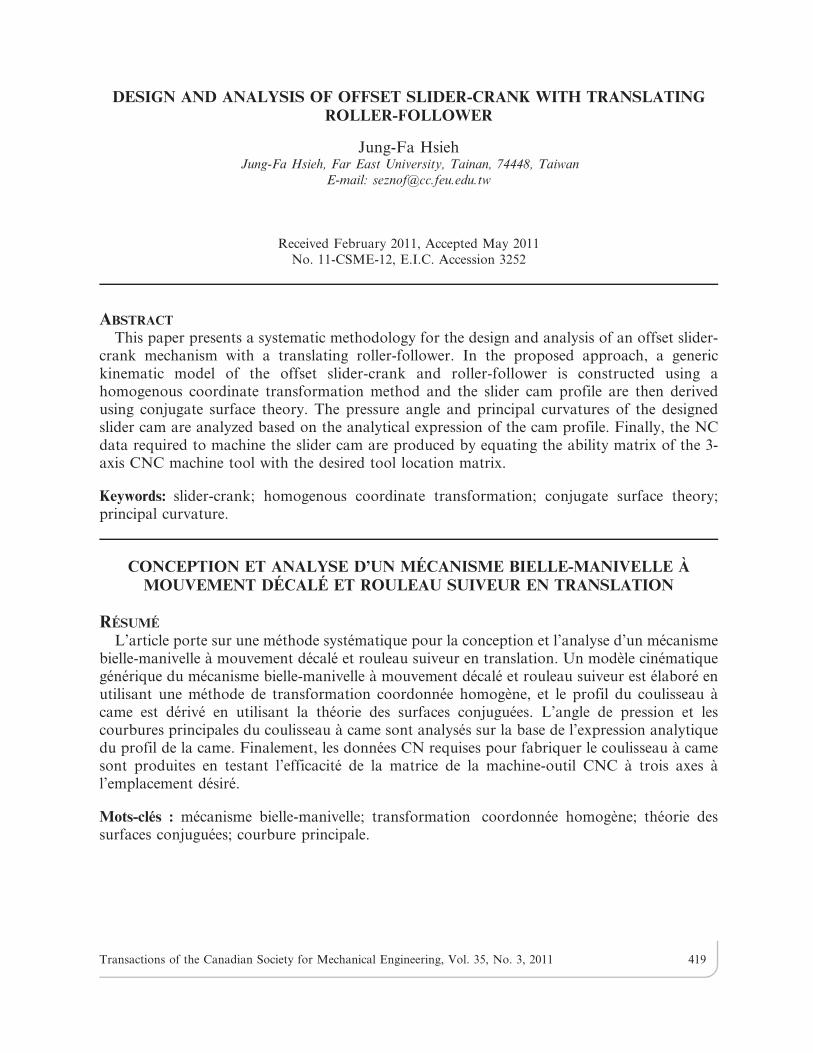
In using the Denavit-Hartenberg (D–H) notation to describe the kinematics of a mechanicalsystem comprising a series of interconnected links, each link is assumed to have two actuatedjoints, i.e. i and iz1 [7]. To describe the kinematic relationship between the links, the followingfour parameters are required (see Fig. 1): (1) the common normal distance ai between the axesof joints i and i+1; (2) the angle ai between the axes of the two joints in a plane perpendicular toai; (3) the link offset bi , i.e. the distance measured along axis zi-1 from 0i-1 (the origin of frame(xyz)i-1) to the intersection of ai and axis zi-1; and (4) the link angle hi , i.e. the angle between xi-1
Transactions of the Canadian Society for Mechanical Engineering, Vol. 35, No. 3, 2011 420
and xi measured in a plane normal to zi-1. The configuration of frame (xyz)i with respect toframe (xyz)i-1 can be expressed as
i{1Ai~ Rot z, hið ÞTrans 0,0, bið Þ Trans ai,0,0ð Þ Rot x,aið Þ
~
Chi {ShiCai ShiSai aiChi
Shi ChiCai {ChiSai aiShi
0 Sai Cai bi
0 0 0 1
2666664
3777775
ð1Þ
where C and S denote COSINE and SINE, respectively.
Figure 2 illustrates the offset slider-crank with translating roller-follower considered in thepresent analysis. As shown, the crank rotates at a constant angular velocity of w3, causing areciprocating motion of the slider cam and a corresponding translation of the roller-follower.The major components of the slider crank mechanism include the crank link, the float link, theslider cam, the translating follower, and a fixed frame. In order to synthesize the cam profile, itis first necessary to number all of the links in the cam mechanism sequentially, starting with theslider cam (marked as "0" in Fig. 2) and ending with the translating roller-follower (marked as"4" in Fig. 2). Although the mechanism shown in Fig. 2 is a closed-loop mechanism, thedesignation "3" refers to the fixed frame rather than the slider since the D–H notation is invalidin the kinematic pair between the slider cam and the meshing element. Once the frames (xyz)i
(i50,..4) have been assigned to link i according to the D–H notation, the kinematic parameterscan be tabulated, as shown in Table 1. The configuration of frame (xyz)4 with respect to frame(xyz)0 is given by
Fig. 1. The Denavit-Hartenberg parameters used for modelling the joints.
Transactions of the Canadian Society for Mechanical Engineering, Vol. 35, No. 3, 2011 421

0A4~P4
i~1
i{1Ai~
1 0 0 m
0 1 0 b4{e
0 0 1 0
0 0 0 1
26664
37775: ð2Þ
Note that b45b4(h3) specifies the input-output relationship of the mechanism. In Fig. 2, theparameter b40 denotes the initial position (i.e. lower dwell position) of the roller-follower, whileb4a is the displacement of the roller-follower in the vertical direction. The configuration of frame(xyz)r (embedded in the roller) with respect to frame (xyz)4 can be expressed as
4Ar~
1 0 0 0
0 1 0 0
0 0 1 0
0 0 0 1
26664
37775: ð3Þ
Meanwhile, the configuration of the roller frame (xyz)r with respect to frame (xyz)0 can beexpressed as
0Ar~0A4
4Ar~
1 0 0 m
0 1 0 b4{e
0 0 1 0
0 0 0 1
26664
37775: ð4Þ
In Fig. 3, the surface equation, rS, and unit outward normal vector, rn, of the meshing elementcan be expressed with respect to frame (xyz)r as follows:
Fig. 2. Offset slider-crank mechanism with translating roller-follower.
Transactions of the Canadian Society for Mechanical Engineering, Vol. 35, No. 3, 2011 422

rS~ rCh rSh u 1½ �T {l=2ƒuƒl=2,0ƒhƒ2p
� �ð5Þ
rn~
LrSLu
| LrSLh
LrSLu
| LrSLh
��� ���~
Ch
Sh
0
0
26664
37775, ð6Þ
where h is the polar angle and l is the width of the roller.
According to conjugate surface theory [8], the cam profile can be determined from themeshing element as follows:
0nT.d0S
dt~ 0Ar
rn� �T d 0Ar
rS� �
dt~0, ð7Þ
where 0S and 0n are the surface equation. and unit outward normal vector with respect to frame(xyz)0, respectively.
According to Eq. (7), if continuous contact is to be maintained between the roller and theslider cam surface, the relative sliding velocity d0S
�dt (where t is the time variable) must be
orthogonal to the common normal 0n at the contact point. Imposing the condition described inEq. (7) on Eqs. (5) and (6), the condition of the conjugate points (denoted as h
�) can be
expressed as
h~{ tan{1 dm
dt
�db4
dt
, ð8Þ
wheredm
dt~ a2Sh3z
a2Sh3{eð Þa2Ch3ffiffiffiffiffiffiffiffiffiffiffiffiffiffiffiffiffiffiffiffiffiffiffiffiffiffiffiffiffiffiffiffiffiffia2
1{ a2Sh3{eð Þ2q
0B@
1CAw3, and
db4
dt~
db4a
dtis the velocity of the roller-
follower and is determined by the motion curve specified for the roller-follower.
The cam profile corresponding to the roller element is obtained by substituting Eq. (8) intoEq. (5), and then transforming rS to frame (xyz)0 via the transformation 0S50Ar
rS, i.e.
Fig. 3. Conical roller location with respect to translating roller-follower.
Transactions of the Canadian Society for Mechanical Engineering, Vol. 35, No. 3, 2011 423

0S~ 0Sx0Sy
0Sz 1� T
~ rChzm rShzb4{e u 1� T
: ð9Þ
Note that the coordinate 0Sy is replaced by rShzb4 for reasons of practical convenience. Thatis, since b4 and h are related through Eq. (8), 0S can be expressed solely in terms of u and h3 forthe given input-output relation b45b4(h3).
3. PRESSURE ANGLE
Having obtained the Eq. of the cam profile, an analytical expression can then be derived forthe pressure angle of the slider cam. The pressure angle, y, is one of the most important designconsiderations in the cam-follower mechanism and is defined as the angle between the directionof the unit normal at the cam-roller contact point and the direction of the velocity of the contactpoint (see Fig. 4) [9]. The pressure angle provides a measure of the efficiency of the forcetransmission between the cam and the follower. Specifically, the smaller the value of y, thebetter the force transmission. The pressure angle at the contact point p between the slider camand the roller is given as
tan y~3np|
3vp
�� ��3np.3vp
�� �� , ð10Þ
Where the unit normal vector of the contact point, 3np, and the direction of the velocity of thecontact point on the roller-follower surface, 3vp, are both defined with respect to frame (xyz)3.
The unit normal vector of the contact point on the roller-follower with respect to frame (xyz)3
is given by
3np~3A4
4Arrnp~ Ch 0 Sh 0
� T: ð11Þ
Fig. 4. Pressure angle of slider cam with translating roller-follower.
Transactions of the Canadian Society for Mechanical Engineering, Vol. 35, No. 3, 2011 424

Meanwhile, the contact point, p, on the roller-follower with respect to frame (xyz)3 is given by
3Sp~3A4
4ArrSp~
3ArrSp~
1 0 0 0
0 0 {1 0
0 1 0 b4
0 0 0 1
26664
37775
rCh
rSh
u
1
26664
37775~
rCh
{u
rShzb4
1
26664
37775: ð12Þ
Since the translating roller-follower translates along the z3 axis, the direction of the velocityof the contact point on the roller-follower surface with respect to frame (xyz)3 can be obtainedas
3vp~d3S
dt~ 0 0
db4
dt0
� �T
: ð13Þ
Using the inner product, the pressure angle, y, can be derived as
tan y~ cot h�� ��: ð14Þ
4. ANALYSIS OF CURVATURE
When machining the slider cam, undercutting occurs if the radius of the cutting tool is greaterthan the minimum absolute value of the radius of curvature of the cam. Similarly, in the roller-follower mechanism, interference between the roller and the slider cam profile occurs if theminimum absolute value of the radius of curvature of the cam is less than the roller radius.Therefore, the principal curvatures of the slider cam surface must be carefully analyzed anddesigned in order to prevent the occurrence of singular points and to generate a geometricallyfeasible mechanism.
In accordance with the principles of differential geometry, the principal curvatures of the camsurface can be evaluated from the derived mathematical model of the slider cam, 0S(h3,u), asfollows:
K1,K2~H+ffiffiffiffiffiffiffiffiffiffiffiffiffiffiffiH2{Kp
, ð15Þ
Where K1 and K2 are the principal curvatures, and H and K are defined as
H~2FM{EN{GL
2(EG{F2),K~
LN{M2
EG{F2ð16Þ
w h e r e L~0n.L20S
L2u, M~0n.
L20S
LuLh3, N~0n.
L20S
L2h3
, E~L0S
Lu.
L0S
Lu, F~
L0S
Lu.
L0S
Lh3a n d
G~L0S
Lh3.
L0S
Lh3(see (A1,A6) in Appendix A).
Transactions of the Canadian Society for Mechanical Engineering, Vol. 35, No. 3, 2011 425
From Eqs. (15) and (16), it can be seen that the principal curvatures of the slider cam arerelated to both the roller-follower motion program and the dimensions of the kinematic modelof the slider-crank.
5. ANALYSIS OF KINEMATIC PERFORMANE
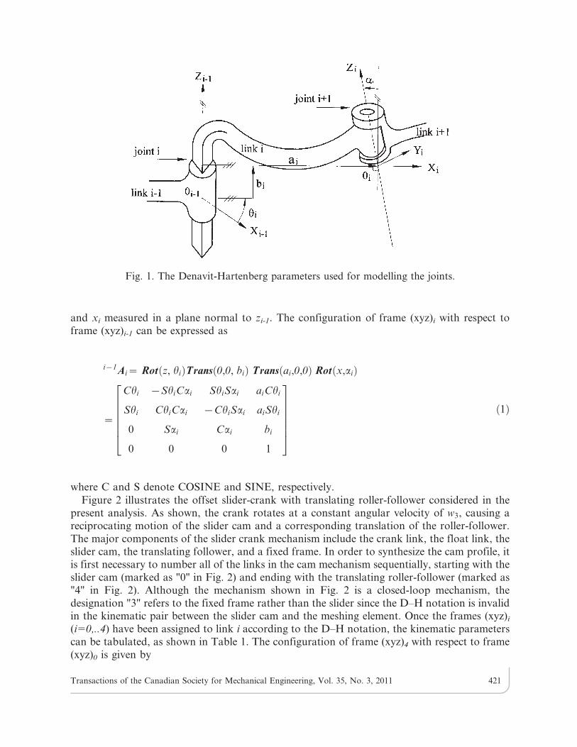
Before the slider cam profile can be designed, it is first necessary to specify a suitable motioncurve for the roller-follower such that the dynamic loading effects are minimized. In this paper,it is assumed that the displacement of the roller-follower is governed by the modified sine curveshown in Fig. 5, in which b4a is the roller-follower displacement in the vertical direction, h3 is thecrank rotational angle, and hd is the dwell period. As shown, the modified sine curve starts fromthe zero position and designates the total rise of the roller-follower during the period of onecrank rotation as h during the period of the crank rotation, t. The equations of displacement,b4a, for the modified sine curve [10] are given as follows:
b4a(h3)~
hp
4zp
h3{hd
t{
1
4 4zpð ÞS 4ph3{hd
t
� �� �,0ƒh3{hdƒ
t
8
h2
4zpz
p
4zp
h3{hd
t{
9
4 4zpð ÞS4p
3
h3{hd
tz
p
3
� �,t
8ƒh3{hdƒ
7t
8
h4
4zpz
p
4zp
h3{hd
t{
1
4 4zpð ÞS 4ph3{hd
t
� �,7t
8ƒh3{hdƒt
8>>>>>>><>>>>>>>:
ð17Þ
Since the slider cam moves back and forth as the input crank rotates through 3600, for eachspecified slider cam position, there exists two corresponding crank angles, as shown in Fig. 6.The forward and backward strokes of the slider cam are a complementary response to a fullcycle of the input crank, but share a common slider cam profile. Therefore, the complete roller-follower motion is described by a double-dwell curve. However, in practice, the roller-followermotion can be analyzed by arbitrarily choosing either the forward stroke or the backwardstroke of the slider cam.
Since the roller-follower motion has the form of a double-dwell curve, it is necessary toconsider six specific positions of the crank rotational angle, i.e. (p1,..p6) (see Fig. 6). Of these sixpositions, positions p1 and p4 are of particular interest since they correspond to the two limitingpositions of the slider-cam. From Fig. 6, positions p1 and p4 can be obtained as
Fig. 5. Modified sine motion curve.
Transactions of the Canadian Society for Mechanical Engineering, Vol. 35, No. 3, 2011 426

p1~Sin{1 e
a1za2
, ð18Þ
p4~Sin{1 e
a1{a2
zp: ð19Þ
Parameter p2 is a design value designated for h3. The slider cam position, s, corresponding to h3
is given by
s~a2Ch3z
ffiffiffiffiffiffiffiffiffiffiffiffiffiffiffiffiffiffiffiffiffiffiffiffiffiffiffiffiffiffiffiffiffiffia2
1{ a2Sh3{eð Þ2q
: ð20Þ
Applying the cosine law, d22 is obtained as
d22~Cos{1 a22z s2ze2� �
{a21
2a2
ffiffiffiffiffiffiffiffiffiffiffiffiffis2ze2p
: ð21Þ
Thus, the crank angle position p6 can be expressed as
Fig. 6. Six segments of roller-follower motion.
Fig. 7. Kinematic analysis of translating roller-follower: (a) displacement diagram; (b) velocitydiagram; (c) acceleration diagram.
Transactions of the Canadian Society for Mechanical Engineering, Vol. 35, No. 3, 2011 427

p6~p2z2p{2d22 ð22Þ
Similarly, the design parameter p3 is designated for h3 and the corresponding position of theslider cam, s, can be obtained by substituting h3 into Eq.(20). Applying the cosine law yields
d33~Cos{1 a22z s2ze2� �
{a21
2a2
ffiffiffiffiffiffiffiffiffiffiffiffiffis2ze2p
: ð23Þ
Fig. 8. Variation of conjugate angle for translating roller-follower.
Fig. 9. Simulated profiles of slider cam.
Transactions of the Canadian Society for Mechanical Engineering, Vol. 35, No. 3, 2011 428
Thus, the crank angle position p5 can be obtained as
p5~p3z2p{2d33 ð24Þ
In the forward stroke of the slider cam, the active period is defined as t5p32p2 and the dwellperiod is given by hd5p2. Conversely, in the backward stroke, the active period is given byt5p52p6 while the dwell period is defined as hd5p5. Therefore, the reciprocating motion of theoffset slider-crank yields an asymmetrical displacement of the roller-follower.
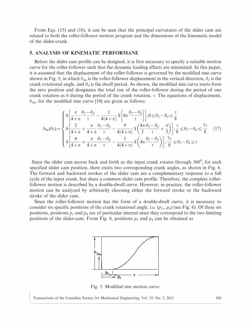
For illustration purposes, this study considers the case of an offset slider-crank andtranslating roller-follower mechanism with the following parameters: a15100 mm, a2560 mm,a35180 mm, e515 mm, b40558 mm, p25300, p351500 and h5100 mm, respectively. CombiningEq. (17) with Eqs. (18) and (24), rotational crank positions p1, p4, p5 and p6 are obtained asp155.3790, p45202.0240, p55245.4670 and p65341.3590, respectively. Figure 7 shows thecorresponding kinematic characteristics of the translating roller-follower for an assumed crankangular velocity of 60 rpm and a roller radius of 8 mm. The variation in the conjugate angle ofthe translating roller-follower can be derived from Eq. (8) and has the form shown in Fig. 8.Meanwhile, the simulated profile of the designed slider cam can be obtained from Eq. (9) and isshown in Fig. 9. Finally, the variation in the principal curvature of the designed slider cam hasthe form shown in Fig. 10.
Once the distance between the main shaft and the translating follower has been determined,i.e. a3, the remaining design parameters can also be derived, namely the link length, the activeperiod, the total rise and the offset. To examine the variation in the pressure angle of the slider-crank, Table 2 presents four illustrative sets of design parameters. Note that to isolate thekinematic effects of the major design parameters, one parameter in each design set isdeliberately assigned a value different from that assigned in the remaining sets. Figure 11presents the pressure angle plots computed using Eq. (14) for the four parameter design sets.Comparing the four figures, it can be seen that the pressure angle is determined primarily by thetotal rise parameter h, but is also strongly affected by parameters p2 and p3, i.e. the active
Fig. 10. Variation of principal curvature of designed slider cam.
Transactions of the Canadian Society for Mechanical Engineering, Vol. 35, No. 3, 2011 429
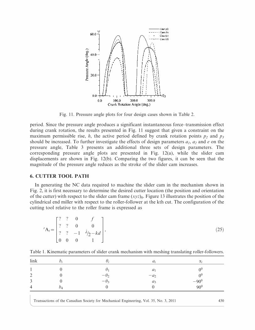
period. Since the pressure angle produces a significant instantaneous force–transmission effectduring crank rotation, the results presented in Fig. 11 suggest that given a constraint on themaximum permissible rise, h, the active period defined by crank rotation points p2 and p3
should be increased. To further investigate the effects of design parameters a1, a2 and e on thepressure angle, Table 3 presents an additional three sets of design parameters. Thecorresponding pressure angle plots are presented in Fig. 12(a), while the slider camdisplacements are shown in Fig. 12(b). Comparing the two figures, it can be seen that themagnitude of the pressure angle reduces as the stroke of the slider cam increases.
6. CUTTER TOOL PATH
In generating the NC data required to machine the slider cam in the mechanism shown inFig. 2, it is first necessary to determine the desired cutter location (the position and orientationof the cutter) with respect to the slider cam frame (xyz)0. Figure 13 illustrates the position of thecylindrical end miller with respect to the roller-follower at the kth cut. The configuration of thecutting tool relative to the roller frame is expressed as
rAt~
? ? 0 f
? ? 0 0
? ? {1 l=2{kd
0 0 0 1
26664
37775, ð25Þ
Fig. 11. Pressure angle plots for four design cases shown in Table 2.
Table 1. Kinematic parameters of slider crank mechanism with meshing translating roller-followers.
link bi hi ai ai
1 0 h1 a1 00
2 0 2h2 2a2 00
3 0 2h3 a3 2900
4 b4 0 0 900
Transactions of the Canadian Society for Mechanical Engineering, Vol. 35, No. 3, 2011 430

where w5kd (d is the allowable cutting depth) and f define the current cutting position. Notethat the third column in Eq. (25) indicates the desired orientation of the cutter axis. Since thecylindrical end miller is a rotational cutting tool, its xt and yt orientations are of no interest.
Combining Eq. (4) and Eq. (25), the desired cutter location with respect to frame (xyz)0 isgiven by
0At~0Ar
rAt~
? ? 0 f zm
? ? 0 b4{e
? ? {1 l=2{kd
0 0 0 1
26664
37775: ð26Þ
Figure 14 presents a schematic illustration of the 3-axis machining center used in the presentstudy. To determine the NC data commands required to machine the cam, it is first necessary tonumber the links of the machining center sequentially, beginning with the clamping system(designated as "0") and ending with the spindle link (designated as "3"). Once the frames i-1–Ai
(i51,2,3) have been assigned according to the D–H notation, the various link parameters can betabulated, as shown in Table 4. Note that b1, b2 and b3 are link variables which control themovements of the machine components. The cutter location matrix with respect to the blankframe (xyz)0 can be expressed as
Table 2. Design parameters for numerical examples in Fig. 11.
a1 a2 p2 p3 h e
Case (a) 100 60 300 1500 100 0Case (b) 90 70 300 1500 100 15Case (c) 100 60 150 1650 100 15Case (d) 100 60 300 1500 50 15
Fig. 12. (a) Pressure angle plots and (b) slider displacement plots for three design cases shown inTable 3.
Transactions of the Canadian Society for Mechanical Engineering, Vol. 35, No. 3, 2011 431

0At~
? ? 0 {b1
? ? 0 {(a3zb2)
? ? {1 a1{b3{d
0 0 0 1
26664
37775: ð27Þ
(Note that the derivation of Eq. (27) is fully described in [11]). Eq. (27) describes theconfiguration of the 3-axis machining center with respect to the slider cam blank.
Referring to Fig. 14, the desired NC position commands for the X-, Y-, and Z-axes of the 3-axis machine relative to the slider cam blank frame (xyz)0 can be expressed as
Fig. 13. Milling cutter location with respect to meshing element.
Fig. 14. 3-axis vertical machine tool.
Transactions of the Canadian Society for Mechanical Engineering, Vol. 35, No. 3, 2011 432

X~f zm, ð28Þ
Y~b4{e, ð29Þ
Z~(l=2){k d : ð30Þ
In order to verify the methodology developed in this study, a slider-crank and translatingroller-follower mechanism with the following parameters was designed: a15100 mm, a2560 mm,a35180 mm, e515 mm, h5100 mm, b40558 mm, p25300, p351500, l510 mm and r58 mm.The input-output relationship was defined in accordance with the modified sine motion curveshown in Fig. 5 and the machined slider cam was based on the backward stroke. The analyticalresults for the principal curvatures of the slider cam revealed that no undercutting took placebetween the cam surface and the cutting tool or roller (i.e. the minimum radius of curvature ofthe cam profile was determined to be 25.707 mm while the cylindrical end miller had a radius of8 mm). The machined slider cam (shown in Fig. 15) was inspected using a coordinate measuringmachine (Mitutoyo BHN-710) [12]. Note that the hole is considered as the reference point of themachined workpiece. i.e. the offset point of the slider cam. Table 5 compares the measuredcoordinates with the design coordinates at designated positions on the cam surface. The resultsindicate that the maximum deviation of the machined surface from the design profile is 20 mm.A satisfactory agreement was found between the measured dimensions and the design profile,
Fig. 15. Measurement of the machined slider cam on 3-axis CMM.
Table 3. Design parameters for numerical examples in Fig. 12.
a1 a2 p2 p3 h e
Case (a) 100 60 300 1500 100 15Case (b) 100 60 300 1500 100 0Case (c) 90 70 300 1500 100 15
Transactions of the Canadian Society for Mechanical Engineering, Vol. 35, No. 3, 2011 433

thus confirming the ability of the proposed methodology to provide a satisfactory description ofthe offset slider-crank mechanism with a translating roller-follower.
7. CONCLUSION
This paper has used a homogenous coordinate transformation method to develop a genericmathematical model of an offset slider-crank mechanism with a translating roller-follower.Given the fundamental design parameters, the proposed methodology not only determines thepressure angle and principal curvature of the slider cam, but also generates the NC datarequired for machining purposes. Moreover, the mathematical model enables the kinematiccharacteristics of the designed mechanism to be systematically explored. Overall, themethodology presented in this study provides an effective approach for the design and analysis
Table 4. Kinematic parameters of the 3-axis milling machine.
link bi hi ai ai
1 b1 900 a1 900
2 b2 900 0 {900
3 b3 {900 a3 00
Table 5. Comparison of designed and measured coordinates at designated points on cam surface.
Designed coordinates Measured coordinates
xi (mm) yi (mm) xi (mm) yi (mm)
20.705 50 20.706 49.99522.105 50 22.106 49.99426.183 50 26.184 49.99633.145 50.091 33.145 50.08543.942 52.403 43.938 52.40655.591 58.604 55.584 58.59867.451 68.17 67.442 68.18579.276 80.433 79.280 80.43490.672 94.465 90.673 94.478101.253 109.104 101.249 109.110110.719 123.076 110.711 123.088118.874 135.120 118.872 135.126125.545 144.094 125.545 144.104130.267 149.016 130.255 149.024131.813 149.947 131.811 149.961134.163 150 134.164 150.020137.325 150 137.326 150.014139.75 150 139.751 150.010141.487 150 141.488 150.010142.551 150 142.552 150.011142.919 150 142.920 150.011
Transactions of the Canadian Society for Mechanical Engineering, Vol. 35, No. 3, 2011 434

of offset slider-cranks with translating roller-followers, and facilitates their manufacture in anautomatic and controllable manner.
REFERENCES
1. Wu, Long-Iong, Chang, Wen-Tung and Liu, Chun-Hsien, ‘‘The design of vary-velocity
translating cam mechanisms,’’ Mechanism and Machine Theory, Vol. 42, pp. 352–364, 2007.
2. Shigly, J.E. and Uicker, J.Jr., Theory of Machines and Mechanisms, McGraw-Hill, New York,
1995.
3. Ghosh, A. and Yadav, R.P., ‘‘Synthesis of cam-follower systems with rolling contact,’’
Mechanism and Machine Theory, Vol. 18, pp. 49–56, 1983.
4. Tsay, D.M. and Hsien, M.W., ‘‘Design and machining of cylindrical cams with translatingconical followers,’’ Journal of Computer-Aided Design, Vol. 25, pp. 655–661, 1993.
5. Tsay, D.M. and Hsien, M.W., ‘‘A general approach to the determination of planar and spatial
cam profiles,’’ ASME Journal of Mechanical Design, Vol. 118, pp. 259–265, 1996.
6. DasGupta, Anirvan and Ghosh, Amitabha, ‘‘On the determination of basic dimensions of a cam
with a translating roller-follower,’’ ASME Journal of Mechanical Design, Vol. 126, pp. 143–147,
2004.
7. Paul, R.P., Robot Manipulators-Mathematics, Programming and Control, MIT press,
Cambridge, Mass 1982.
8. Chakraborty, J. and Dhande, S.G., Kinematics and Geometry of Planar and Spatial Cam
Mechanisms, John Wiley & Sons, New York, 1977.
9. Gonzalez-Palacios, M. A. and Angeles, J., Cam Synthesis, Kluwer Academic Publisher, 1993.
10. Jensen, Preben W., Cam design and manufacture, Marecl Dekker, Inc., 1987.
11. Hsieh, J.-F., ‘‘Application of homogenous transformation matrix to the design and machining
of a geneva mechanism with curved slots,’’ Proc. Instn. Mech. Engrs, Part C: J. Mechanical
Engineering Science, Vol. 221 pp. 1435–1443, 2007.
12. Hsieh, J.-F. and Lin, P. D., ‘‘Application of homogenous transformation matrix to
measurement of cam profiles on coordinate measuring machines,’’ Journal of Machine Tools
& Manufacture, Vol. 47, pp. 1593–1606, 2007.
APPENDIX A
The principal curvature of the slider surface can be evaluated by Eqs. (15) and (16), and theirrelated parameters have been derived as the following:
L~0 ðA1Þ
M~0 ðA2Þ
Transactions of the Canadian Society for Mechanical Engineering, Vol. 35, No. 3, 2011 435
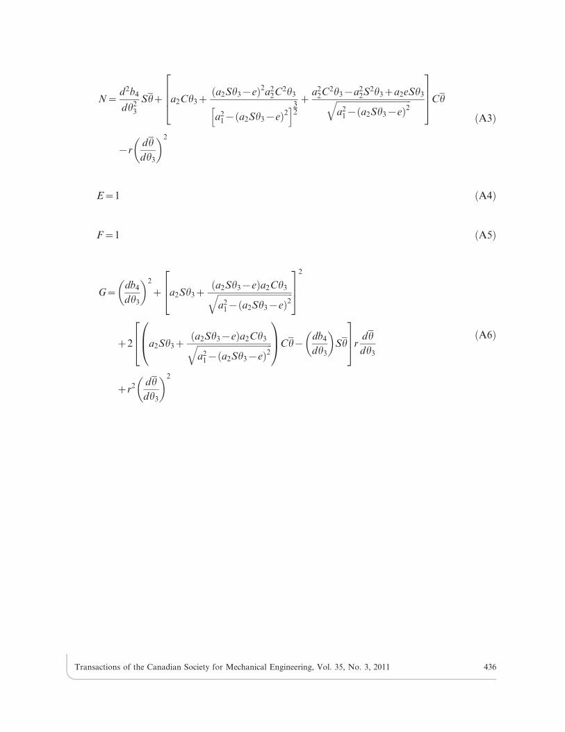
N~d2b4
dh23
Shz a2Ch3za2Sh3{eð Þ2a2
2C2h3
a21{ a2Sh3{eð Þ2
h i32
za2
2C2h3{a22S2h3za2eSh3ffiffiffiffiffiffiffiffiffiffiffiffiffiffiffiffiffiffiffiffiffiffiffiffiffiffiffiffiffiffiffiffiffiffi
a21{ a2Sh3{eð Þ2
q2664
3775Ch
{rdh
dh3
2
ðA3Þ
E~1 ðA4Þ
F~1 ðA5Þ
G~db4
dh3
2
z a2Sh3za2Sh3{eð Þa2Ch3ffiffiffiffiffiffiffiffiffiffiffiffiffiffiffiffiffiffiffiffiffiffiffiffiffiffiffiffiffiffiffiffiffiffia2
1{ a2Sh3{eð Þ2q
264
375
2
z2 a2Sh3za2Sh3{eð Þa2Ch3ffiffiffiffiffiffiffiffiffiffiffiffiffiffiffiffiffiffiffiffiffiffiffiffiffiffiffiffiffiffiffiffiffiffia2
1{ a2Sh3{eð Þ2q
0B@
1CACh{
db4
dh3
Sh
264
375r
dh
dh3
zr2 dh
dh3
2
ðA6Þ
Transactions of the Canadian Society for Mechanical Engineering, Vol. 35, No. 3, 2011 436


![Ballscrew Efficiency Modeling in a Crank-Slider …embeddedlab.csuohio.edu/Prosthetics/media/HWarner.pdfbond graph modeling method can be found in [1]. ... Crank-Slider Prosthetic](https://static.fdocuments.us/doc/165x107/5b1c51377f8b9a1b688b7b63/ballscrew-efficiency-modeling-in-a-crank-slider-graph-modeling-method-can-be-found.jpg)