Design and Analysis for a CubeSat Mission - CORE
95
Worcester Polytechnic Institute Digital WPI Major Qualifying Projects (All Years) Major Qualifying Projects February 2013 Design and Analysis for a CubeSat Mission Dylan Raymond Billings Worcester Polytechnic Institute Francis Stephen Hoey Worcester Polytechnic Institute Ilea Shaneen Graedel Worcester Polytechnic Institute Justin Michael Torres Worcester Polytechnic Institute Nicolas Martinez Worcester Polytechnic Institute See next page for additional authors Follow this and additional works at: hps://digitalcommons.wpi.edu/mqp-all is Unrestricted is brought to you for free and open access by the Major Qualifying Projects at Digital WPI. It has been accepted for inclusion in Major Qualifying Projects (All Years) by an authorized administrator of Digital WPI. For more information, please contact [email protected]. Repository Citation Billings, D. R., Hoey, F. S., Graedel, I. S., Torres, J. M., Martinez, N., & Lavallee, P. K. (2013). Design and Analysis for a CubeSat Mission. Retrieved from hps://digitalcommons.wpi.edu/mqp-all/3709
Transcript of Design and Analysis for a CubeSat Mission - CORE

Worcester Polytechnic InstituteDigital WPI
Major Qualifying Projects (All Years) Major Qualifying Projects
February 2013
Design and Analysis for a CubeSat MissionDylan Raymond BillingsWorcester Polytechnic Institute
Francis Stephen HoeyWorcester Polytechnic Institute
Ilea Shaneen GraedelWorcester Polytechnic Institute
Justin Michael TorresWorcester Polytechnic Institute
Nicolas MartinezWorcester Polytechnic Institute
See next page for additional authors
Follow this and additional works at: https://digitalcommons.wpi.edu/mqp-all
This Unrestricted is brought to you for free and open access by the Major Qualifying Projects at Digital WPI. It has been accepted for inclusion inMajor Qualifying Projects (All Years) by an authorized administrator of Digital WPI. For more information, please contact [email protected].
Repository CitationBillings, D. R., Hoey, F. S., Graedel, I. S., Torres, J. M., Martinez, N., & Lavallee, P. K. (2013). Design and Analysis for a CubeSat Mission.Retrieved from https://digitalcommons.wpi.edu/mqp-all/3709

AuthorDylan Raymond Billings, Francis Stephen Hoey, Ilea Shaneen Graedel, Justin Michael Torres, NicolasMartinez, and Peter Kendall Lavallee
This unrestricted is available at Digital WPI: https://digitalcommons.wpi.edu/mqp-all/3709


I
Abstract
This project supports the design of a three-unit Cube Satellite (CubeSat) mission in a high-
altitude, polar, sun-synchronous orbit. The goal is to perform solar and extraterrestrial X-ray
spectroscopy using the Sphinx-NG instrument. The CubeSat design addresses the mission and
the Poly-Picosatellite Orbital Deployer (P-POD) requirements. Mechanical design of the Cubesat
is performed using SolidWorks. Vibration and stress analysis for expected launch conditions is
performed using SolidWorks. Orbital decay analysis is performed using Systems Toolkit and
NASA’s Debris Assessment Software. The magnetic fields induced by CubeSat’s three magnetic
torquers are evaluated using COMSOL. Documents and procedures relevant to compliance with
the P-POD are identified.
“Certain materials are included under the fair use exemption of the U.S. Copyright Law and
have been prepared according to the fair use guidelines and are restricted from further use."
II
Acknowledgements
We would like to thank the following individuals and groups for their help and support
throughout the entirety of this project.
Project Advisor Professor Nikolaos Gatsonis
ADC Team Professor Demetriou and students Assaad Farhat, Jighjigh Ivase, Ye Lu,
Alan Snapp
STTP Team Professor Blandino and students Jennifer Hanley, Brian Joseph, Martha
Miller, Samantha Monte, Joshua Trudeau, Racheal Weinrick
III
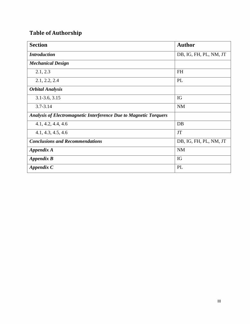
Table of Authorship
Section Author
Introduction DB, IG, FH, PL, NM, JT
Mechanical Design
2.1, 2.3 FH
2.1, 2.2, 2.4 PL
Orbital Analysis
3.1-3.6, 3.15 IG
3.7-3.14 NM
Analysis of Electromagnetic Interference Due to Magnetic Torquers
4.1, 4.2, 4.4, 4.6 DB
4.1, 4.3, 4.5, 4.6 JT
Conclusions and Recommendations DB, IG, FH, PL, NM, JT
Appendix A NM
Appendix B IG
Appendix C PL

IV
Table of Contents
Table of Figures ............................................................................................................................................ 5
List of Tables ................................................................................................................................................ 5
1 Introduction ........................................................................................................................................... 6
1.1 Overview of Previous CubeSat Missions ...................................................................................... 7
1.2 Review of WPI’s CubeSat Designs .............................................................................................. 8
1.2.1 Mechanical, Thermal, and Power Subsystems ...................................................................... 9
1.2.2 Attitude Determination And Control System Design For a CubeSat Mission .................... 10
1.3 Subsystem Design ....................................................................................................................... 11
1.3.1 Design Approach................................................................................................................. 11
1.4 Objectives, Approach, and Methods ........................................................................................... 13
2 Mechanical Design .............................................................................................................................. 14
2.1 Requirements (P-POD 3.0) ......................................................................................................... 14
2.2 Current CubeSat Configuration .................................................................................................. 27
2.3 Redesign of Mechanical Components ......................................................................................... 30
2.4 Useful Documentation for Future MQPs .................................................................................... 34
3 Orbital Analysis .................................................................................................................................. 36
3.1 Poly-Picosatellite Orbital Deployer ............................................................................................ 36
3.2 NASA Procedural Requirements for Limiting Orbital Debris .................................................... 36
3.3 US Government Orbital Debris Mitigation Standard Practices .................................................. 38
3.4 NASA Safety Standard: Guidelines Assessment Procedures for Limiting Orbital Debris ......... 39
3.5 NASA Handbook for Limiting Orbital Debris............................................................................ 41
3.6 Technical Probabilistic Risk Assessment Procedures for Safety and Mission Success for NASA
Programs and Projects ............................................................................................................................. 41
3.7 Notification of Intent to Decommission or Terminate Operating Space Systems and Terminate
Missions .................................................................................................................................................. 42
3.8 Biological Contamination Control for Outbound and Inbound Planetary Spacecraft................. 43
3.9 Risk Management Procedural Requirements .............................................................................. 43
3.10 Planetary Provisions for Robotic Extraterrestrial Missions ........................................................ 43
3.11 Safety and Mission Assurance Audits, Reviews, and Assessments ............................................ 44
3.12 Technical Report on Space Debris, Scientific and Technical Subcommittee of the United
Nations. ................................................................................................................................................... 44
3.13 Orbital Decay Analysis ............................................................................................................... 45

V
3.14 Systems Toolkit .......................................................................................................................... 45
3.15 Debris Assessment Software (DAS) ........................................................................................... 46
4 Analysis of Electromagnetic Interference Due to Magnetic Torquers ................................................ 51
4.1 Magnetometer on the WPI CubeSat ............................................................................................ 51
4.2 Magnetic Torquers ...................................................................................................................... 52
4.3 Analytical Modeling the Induced Field from a Solenoid ............................................................ 54
4.4 Simulation of a Single Magnetic Torquer in Free Space ............................................................ 55
4.5 Simulation of Three Magnetic Torquers ..................................................................................... 57
4.6 Permeability of the Pumpkin Structure ....................................................................................... 59
5 Conclusions and Recommendations ................................................................................................... 61
5.1 Finalize All Internal Components and Locations Within the CubeSat ....................................... 61
5.2 Complete Compliance Between the CubeSat Structure and the SPHINX-NG Payload ............. 61
5.3 Acquire an Accurate and Complete SolidWorks Model of the Solar Panel Hinges and Update
the CubeSat SolidWorks Model .............................................................................................................. 63
5.4 Determine How the Solar Panels Will Deploy ........................................................................... 63
5.5 Complete Remaining P-POD Requirements ............................................................................... 63
5.6 Generate the Correct Wiring From Each Internal Device to Accurately Reflect the Entire Final
CubeSat ................................................................................................................................................... 63
5.7 Magnetic Shielding for the Magnetometer ................................................................................. 64
6 Appendix A: Foreign CubeSat Missions ............................................................................................ 66
7 Appendix B: Reference Documents .................................................................................................... 68
8 Appendix C: P-POD Requirements Checklist .................................................................................... 77
9 References ........................................................................................................................................... 90

5
Table of Figures
Figure 1: Final 2012 CubeSat Design ........................................................................................................... 8
Figure 2: P-POD Enclosure with Coordinate System ................................................................................. 15
Figure 3: CubeSat Axis Orientation ............................................................................................................ 17
Figure 4: CubeSat Deployment Switch and Separation Spring Placement Drawing .................................. 20
Figure 5: CubeSat Deployment Switch ....................................................................................................... 21
Figure 6: CubeSat Rails and Access Ports .................................................................................................. 22
Figure 7: Acceleration Spectral Density vs Frequency Curve .................................................................... 24
Figure 8: Top-Bounded Stresses (Left) and Deformation (Right) .............................................................. 25
Figure 9: Fully Bounded Stresses (Left) and Deformation (Right) ............................................................ 25
Figure 10: Exploded Isometric View of the CubeSat ................................................................................. 28
Figure 11: Stowed (Left)/ Deployed (Right) Satellite Configuration ......................................................... 29
Figure 12: Faces of CubeSat ....................................................................................................................... 29
Figure 13: Original Circuit (Left) and Vertical Circuit Stack (Right) ........................................................ 30
Figure 14: ISIS Antenna ............................................................................................................................. 31
Figure 15: Orbital History for Satellite at 640 km altitude. Obtained from DAS. ...................................... 50
Figure 16: Orientation of Satellite with Respect to Earth ........................................................................... 52
Figure 17: ZARM Technik Magnetic Torquers .......................................................................................... 53
Figure 18: Force Vector as a Result from Magnetic Torquer ..................................................................... 54
Figure 19: Magnetic Flux of a Single Magnetic Torquer ........................................................................... 56
Figure 20: Streamlines of the Magnetic Field of a Single Magnetic Torquer ............................................. 57
Figure 21: Mutlislice of Magnetic Flux Normal of Three Magnetic Torquers ........................................... 58
Figure 22: Streamlines of the Magnetic Field Due to Three Magnetic Torquers ....................................... 58
Figure 23: B Field Acting on Structure with Relative Permeability of 50000 ............................................ 59
Figure 24: B Field Acting on Structure with Relative Permeability of 1.0 ................................................. 60
Figure 25: Overlap Between SPHINX-NG and Pumpkin Structure ........................................................... 62
Figure 26: SPHINX-NG Sun Sensors Obstructed by Skeleton .................................................................. 62
Figure 27: SPHINX-NG Radiator Interfering With CubeSat Rails ............................................................ 62
List of Tables
Table 1: Random Vibration Test Levels ..................................................................................................... 23
Table 2: Orbital Parameters ........................................................................................................................ 47
Table 3: Orbital Lifetime Original Results ................................................................................................. 48
Table 4: Orbital Lifetime, 2nd
Iteration ....................................................................................................... 49

6
1 Introduction
California Polytechnic State University (Cal Poly) and Stanford University developed a uniform
platform that allows universities and industry to design, test, and integrate cubical satellites that
come in units of 10x10x10 cm and referred to as CubeSats (CubeSat in the News ; PolySat). Bob
Twiggs, a former professor at Stanford University, and Jordi Puig-Sauri, professor at Cal Poly,
created CubeSat standard procedures for testing and launch approval (Morehead State
University; Earth and Space Science; Twiggs, Robert J). CubeSat are an effective and cost
affordable way to place payloads in Low Earth Orbit.
A CubeSat unit (1U) is a 10-cm cube with a mass of approximately 1.33 kg designed to carry a
particular payload and perform specified tasks in orbit (CubeSat in the News, 2012). The
CubeSat must be carefully designed to the specifications outlined by Cal Poly and Stanford. The
teams also deploy their CubeSat from a spring loaded device called the Poly-Picosatellite Orbital
Deployer (P-POD). The documentation for this deployer clarifies all the testing, requirements
and procedural steps that must be taken in order to ensure that the CubeSat does not endanger its
payload, mission, other CubeSats, or the launch vehicle delivering it into space (Cal Poly, 2011).
In addition, Cal Poly and Stanford provide documentation, licenses, and design guidelines to all
teams adhering to the CubeSat program.
This MQP involves design and analysis of a WPI CubeSat mission. The goal of our mission is to
place a 3-unit Cube Sat into a sun-synchronous 500-800 km polar orbit for the purpose of space
weather observation, specifically solar and terrestrial X-ray spectroscopy.

7
1.1 Overview of Previous CubeSat Missions
During 2011 there was only one CubeSat mission, Jugnu, developed by the Indian Institute of
Technology Kanpur (ITT Kanpur). However, there has been a considerable increase in CubeSat
missions during 2012. In February the first Vega rocket lifted off from the Guiana Space Center,
successfully placing seven European CubeSats into orbit, including the first satellites ever for
Romania, Hungary and Poland. Furthermore, the Japanese HTV-3 cargo vessel blasted off from
the Tanegashima Space Center on July 21st, carrying five CubeSats to the International Space
Station (one of them built by San Jose State University), where they will be deployed into space
from the Kibo module. Seven more missions are scheduled for 2012, including Singaporean,
Ecuadorian and Peruvian satellites. Approximately seven more missions are planned for 2013
and 2014.
CubeSat’s have been found to be quite useful when it comes to cost and applications. NASA
created the CubeSat Launch Initiative (CSLI) which allows for small satellites to be flown on
previously planned missions into orbit. The small satellite payloads are considered to be an
auxiliary to the planned missions. NASA has already selected its third round of CubeSats, part
of the CSLI, which entail 33 CubeSat’s. As part of the CSLI, the Educational Launch of
Nanosatellites was created for universities and private companies to take part in the mission.
These missions will take place between 2013 and 2014. Most of these CubeSat’s are from
Universities across the United States. CubeSat’s have made a major contribution to educational
programs allowing students to get firsthand experience in the aerospace industry. Some colleges
that are taking part in the next batch of the CSLI are Massachusetts Institute of Technology,
Cornell University, and California Polytechnic State University. CubeSat’s create innovation and

8
help increase the testing of new technologies, which is a sector of the United States space
program that is currently leading the industry.
1.2 Review of WPI’s CubeSat Designs
WPI has been undergoing design of a CubeSat that carries onboard the Sphinx-NG instrument.
The design shown in figure 1 was accomplished with three MQP groups (Bauer et al., 2012;
Dawson, Nassiff, & Velez, 2012a; Dopart, Morlath, Oliver, & Schomaker, 2012). The Sphinx-
NG instrumnent is shown at the bottom 1U in Fig. 1. Sphinx-NG’s pointing requirements
necessitate high-accuracy sensors for attitude determination and control. The spacecraft will be
3-axis stabilized with magnetic torquers, and the four solar-facing detectors must point towards
the Sun with a ±1 degree of accuracy. This requires various sensors, including GPS, a
magnetometer, and a sun sensor. The entire CubeSat has a power capability of 15W.
Figure 1: Final 2012 CubeSat Design
9
1.2.1 Mechanical, Thermal, and Power Subsystems
The MQP team (Dopart et al., 2012) focused on the mechanical, thermal, and power subsystems
for the CubeSat. They provided analyses and recommendations about the respective subsystems
of the satellite. They performed analysis in SolidWorks and COMSOL using a thorough CAD
model of the satellite and all of its components.
The body chosen for the satellite was the Pumpkin brand body, chosen for its flight heritage and
simplicity. It is a mono-block body made from anodized aluminum. Using the information
provided by Pumpkin, the MQP team performed analysis of the structure to see that it could
withstand the random vibrations and normal stresses it would experience during a launch
sequence. They were satisfied that the body of the satellite itself would not strain or otherwise
deform to an extent worth consideration, even during the simulation of the ‘worst case scenario’
launch vibration profile.
For CubeSats operating in low Earth orbits (LEO) certain thermal considerations must be
accounted for. The main sources of thermal radiation considered were solar, albedo, and earth
radiation. Using COMSOL, the team (Dopart et al., 2012) calculated the thermal variances
across the satellite’s surfaces over several simulated orbits. The main factor across each orbit
was that the satellite was at its highest surface temperature when facing the sun and at its lowest
temperature when in eclipse. The team also used COMSOL to analyze the conduction of heat
from the internal components of the CubeSat. Their data showed that the satellite would range
between approximately 200 K and 300 K throughout its orbits. They also performed individual
thermal analyses on many of the individual parts within the satellite, which can be found in detail
within the findings of their report.

10
The team also constructed a solar testing array for the lab option satellite, which was partially
constructed for lab experimenting without having to construct a full version of the satellite. They
created digital instruments in LabView so that when a lab option satellite was ready to be tested,
there would be instruments and some preliminary experiments ready to be run.
1.2.2 Attitude Determination And Control System Design For a CubeSat Mission
A second MQP group in 2011-2012 was responsible for the Attitude Determination and Control
System (ADC) and provided hardware selection, determination of algorithm selection, control
policy selection, ADC simulation development, and software and hardware test development
(Dawson, Nassiff, & Velez, 2012b). The primary mission of the SPHINX-NG is to perform solar
and terrestrial X-ray spectroscopy which requires ± 2 degrees of accuracy pointing towards the
center of the sun to perform this task. The 2011 ADC team was responsible for determining the
hardware and attitude determination algorithms to bring the CubeSat to stability from de-
tumbling, initial attitude determination, and attitude maintenance. The team determined the
hardware and algorithms needed as well as provided a set of recommendations for the future
ADC teams.
The team decided to use five coarse sun sensors with a sixth fine sun sensor placed on each side
of the CubeSat. This would allow the CubeSat to be able to determine its position relative to the
sun independent of which face of the CubeSat is facing the sun. The team also researched
various gyroscopes and determined that the ADXRS450 model from Analog Devices was the
most accurate model despite being slightly more expensive. The team determined that the
CubeSat would use the ZARM Technik MTO.2-1 magnetic torquer on each axis of the satellite.
This will allow the CubeSat to physically orientate itself in space.

11
The TRIAD method was selected for initial attitude determination. The TRIAD method has been
successfully used on many other CubeSat missions. The team also looked into various other
methods such as the Wahba equation, the Quaternion Estimator Method, and the use of Kalman
Filters. These methods were tested in MATLAB to determine accuracy, efficiency, and
computing power. The team provided recommendations of algorithms for future ADC teams to
examine that could minimize computing power and increase accuracy (Dawson et al., 2012b).
1.3 Subsystem Design
1.3.1 Design Approach
The mission requirements outlined in the previous section lay out a structured and well-defined
foundation upon which to build a full CubeSat mission. To ensure that each of these
requirements are met, a 16-person CubeSat team was divided into three MQP groups: Instrument
and Mission Analysis (IMA), Attitude Determination and Control (ADC), and Structural,
Thermal, and Power. The responsibilities of each team are outlined below.
1.3.1.1 Design and Analysis
The Instrument and Mission Analysis team, consisting of six members, and is responsible for the
following:
1. Mechanical Design
2. Orbital Analysis
3. Analysis of Electromagnetic Interference Due to Magnetic Torquer
1.3.1.2 Attitude Determination and Control
The Attitude Determination and Control (ADC) team, consisting of four members, was
responsible for the following:
1. Sun Sensor and Magnetic Torquer Hardware Selection
2. Determination Algorithm Selection

12
3. Control Policy Selection
4. ADC Simulation Development
5. Software and Hardware Test Development
For a detailed review of the ADC team’s objectives and results, refer to MQP Report MAD-
D11A.
1.3.1.3 Thermal, Power, and Telecommunications
The Structural, Thermal, and Power team, consisting of a combined six members, was
responsible for the following:
1. Thermal Analysis
2. Power Distribution System
3. Power Usage Tracking
4. Telecommunications
For a detailed review of the Structural, Thermal, and Power team’s objectives and results, refer
to MQP Report JB3-CBS2.
1.3.1.4 Systems Engineering Group
The success of this project was dependent on the effective integration of these three separate
teams into one inclusive Systems Engineering Group, or SEG. This integration was achieved
through weekly SEG meetings, during which each team shared their updated action items,
approaches, and developing results. These SEG meeting ensured that each team was aware of the
decisions and conclusions reached by the other teams, and enabled the members to subsequently
revise their own work if affected by new developments. By structuring these meetings based on a
comprehensive list of project action items, the SEG meetings also provided an overall view of
the project’s progress. In addition to the SEG meetings, the IMA and ADC teams held a
13
combined weekly meeting to address in more detail the concerns that linked their two
subsystems.
1.4 Objectives, Approach, and Methods
The objectives, approach, and methods for our team’s responsibilities are outlined below.
1. Mechanical Design
Use SolidWorks to perform structural survivability and test Pumpkin structure
against General Environmental Verification Standard (GEVS) worst case scenario
launch profile following the P-POD…..
Make changes to satellite design to reflect P-POD and other mission requirements
Maintain updated CAD model representation.
2. Orbital Analysis
Identify P-POD orbital requirements and applicable documents’ requirements.
Use Systems Toolkit (STK) and Debris Assessment Software (DAS) to determine
orbital lifetime of CubeSat.
Create Excel spreadsheet quick reference guides for applicable documents’
requirements.
Create file of highlighted reference documents for future ease of use.
3. Analysis of Electromagnetic Interference Due to Magnetic Torquer
Use COMSOL to simulate magnetic field of magnetic torquers
Determine if magnetic shielding is required for magnetometer

14
2 Mechanical Design
This section highlights the primary factors which affect the mechanical design of the CubeSat.
Foremost among these factors is the P-POD document, which provides key requirements for the
CubeSat that must be met in order for the launch and integration into the launch vehicle to be
successful. Ensuring a successful mission for the SPHINX-NG is the next most important factor
affecting the mechanical design choices made by the design team. This meant ensuring that the
satellite can perform its primary duty once it reaches space. Finally, the last factor considered
when designing the CubeSat is the simplicity of construction for future teams, which is critical in
ensuring that the satellite can be produced and maintained with relative ease. In this way, the
design team aimed to achieve regulatory requirements, mission requirements, and construction
requirements for the CubeSat.
2.1 Requirements (P-POD 3.0)
The Flight CubeSat Mission and Design specifically mentions several requirements that the
CubeSat must comply with. For example, the CubeSat is not allowed to have any type of
propulsion system or explosives on board. Several restrictions are designed to ensure the safety
of satellites, payloads, and launch vehicles. Compliance with this section is investigated
primarily through inspection to make sure that all requirements are followed. The mechanical,
electrical, and environmental sections define requirements designed to make sure that the
CubeSat can successfully integrate into the P-POD chamber shown in Figure 2. There are certain
time delays that must be followed that affect both the mechanical components as well as the
electrical components. Many of these requirements meet compliance through inspection,
analysis, or testing. Without having a physical prototype, the design team is capable of

15
completing the inspection and analysis requirements. All the testing must be performed once the
entire CubeSat has been constructed.
Figure 2: P-POD Enclosure with Coordinate System (P-POD, 2011)
Flight CubeSat Mission and Design (P-POD 3.1)
CubeSat Design (P-POD 3.1.1)
The CubeSats shall be self-contained, and provide their own power, sequencing, and wiring.
Pressure Vessels (P-POD 3.1.2)
The CubeSat shall not contain pressurized vessels.
Propulsion Systems (P-POD 3.1.3)
The CubeSat shall not contain propulsion systems.
Radioactive Material (P-POD 3.1.4)
The CubeSat shall not contain radioactive material.
Explosive Devices (P-POD 3.1.5)
16
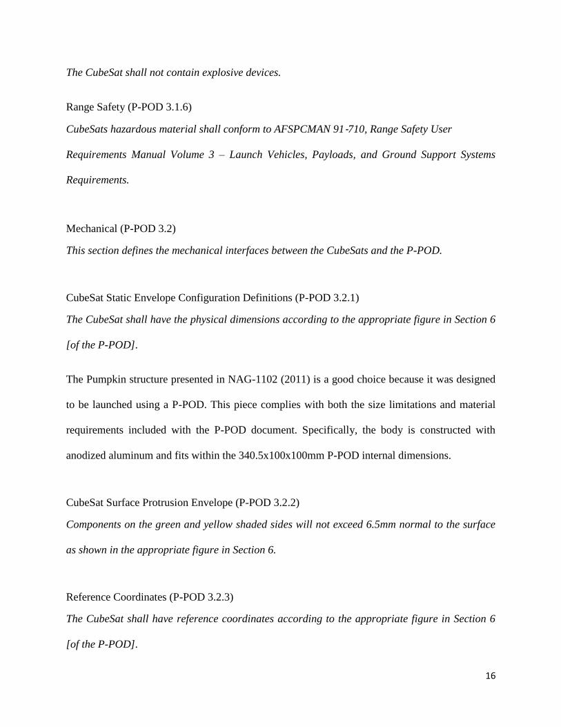
The CubeSat shall not contain explosive devices.
Range Safety (P-POD 3.1.6)
CubeSats hazardous material shall conform to AFSPCMAN 91‐710, Range Safety User
Requirements Manual Volume 3 – Launch Vehicles, Payloads, and Ground Support Systems
Requirements.
Mechanical (P-POD 3.2)
This section defines the mechanical interfaces between the CubeSats and the P-POD.
CubeSat Static Envelope Configuration Definitions (P-POD 3.2.1)
The CubeSat shall have the physical dimensions according to the appropriate figure in Section 6
[of the P-POD].
The Pumpkin structure presented in NAG-1102 (2011) is a good choice because it was designed
to be launched using a P-POD. This piece complies with both the size limitations and material
requirements included with the P-POD document. Specifically, the body is constructed with
anodized aluminum and fits within the 340.5x100x100mm P-POD internal dimensions.
CubeSat Surface Protrusion Envelope (P-POD 3.2.2)
Components on the green and yellow shaded sides will not exceed 6.5mm normal to the surface
as shown in the appropriate figure in Section 6.
Reference Coordinates (P-POD 3.2.3)
The CubeSat shall have reference coordinates according to the appropriate figure in Section 6
[of the P-POD].

17
In order to reflect the features and proportions of this skeleton, our team re-designed the existing
CAD representation of the CubeSat to include a more detailed version of the Pumpkin skeleton
than the previous iteration. This provides several advantages to the older model, including a
chance to reorient the CubeSat's axis labels to correspond to the mandatory configuration
indicated in the P-POD. The required axis for the CubeSat can be seen in Figure 3 below. The
requirements are that the CubeSat be inserted into the P-POD negative Z-face first. In the new
CAD drawing, the bottom of the CubeSat is now oriented in the positive Z direction, in order to
comply with the P-POD coordinate system. Another benefit that arises due to the new CAD
skeleton include being able to identify areas where components may collide with the Pumpkin
structure, which turned out to be a significant factor in the placement of the internal components
when adding them back into the new body of the satellite.
Figure 3: CubeSat Axis Orientation
Y
Z
X

18
CubeSat Orientation in P-POD (P-POD 3.2.3.1)
The –Z face of the CubeSat will be inserted first into the P-POD.
P-POD Reference Coordinates (P-POD 3.2.3.2)
The P-POD shall use the coordinate system as defined in Figure 1 [of the P-POD]. The origin of
the P-POD coordinate system is centered on the back panel. Once fully integrated into the P-
POD, the CubeSat and P-POD coordinate system are the same.
CubeSat Mass Properties (P-POD 3.2.4)
The APIC will use the delivered CubeSat mass properties as the final mass properties statement.
CubeSat Mass Property Uncertainty (P-POD 3.2.4.1)
The actual final CubeSat mass properties will not deviate from the final statement beyond the
tolerance values specified in Table 1[of the P-POD].
CubeSat Mass Properties Requirements (P-POD 3.2.4.2)
All CubeSat mass properties will be expressed in the respective CubeSat coordinate system, in
the as-delivered, stowed flight configuration, with Moment of Inertia (MOI) being calculated
about the CubeSat center of gravity (cg) and Products of Inertia (POI) expressed as either
positive or negative.
CubeSat Mechanical Deployment (P-POD 3.2.5)
Exterior CubeSat components shall not contact the interior surface of the P-POD, in addition to
the designated CubeSat rails, in any way that would cause resistance upon deployment.
19
CubeSat Deployables Constraint (P-POD 3.2.5.1)
All CubeSat deployables shall be constrained by the CubeSat and not use the P-POD to
constrain deployables.
CubeSat Rail Material (P-POD 3.2.6)
The CubeSat rails and standoffs which contact the P-POD interior surfaces shall be hard
anodized aluminum. The P-POD rails are also hard anodized with Teflon impregnation to
reduce friction.
CubeSat Material Selection (P-POD 3.2.9)
CubeSat Materials shall be selected in accordance with NASA-Technical-STD-6016 (Section
4.2), Standard Materials and Processes Requirements for Spacecraft.
Electrical (P-POD 3.3)
This section defines the electrical interfaces between the CubeSats and the P-POD.
CubeSat Power State (P-POD 3.3.1)
The CubeSat power system shall be at a power off state to prevent CubeSats from activating any
powered functions while integrated in the P-POD from the time of delivery to LV through on
orbit deployment. CubeSat powered functions include the variety of subsystems such as
Command and Data Handling (C&DH), RF Communications, Attitude Determination and
Control (ADC), deployable mechanism actuations. CubeSat power system includes all battery
assemblies and solar cells.

20
The Pumpkin skeleton also has essential features such as a pre-installed P-POD integration
switch. This switch is mandatory for P-POD launches, and it disables the on-board power of the
CubeSat when it is enclosed in the P-POD. The location of the switch is shown in Figure 4; the
switches are located on the corner rubber knobs at the end of the CubeSat structure.
Figure 4: CubeSat Deployment Switch and Separation Spring Placement Drawing (Cubesat to P-
POD Interface Control Document For the OUTSat Mission)
The integration switch shown in Figure 5 included in the Pumpkin structure takes up a small but
noticeable volume in the corner of the CubeSat. Because the integration switches need to be
located at the bottom of the satellite, this switch box would conflict with the location of the
SPHINX-NG payload. Because of this, we decided to invert the design of the CubeSat so that the
'bottom' of the satellite is on the opposite end from the SPHINX-NG. This means that when the
satellite is ejected from the P-POD, the SPHINX-NG will exit the P-POD first.

21
Figure 5: CubeSat Deployment Switch
CubeSat Deployment Switch Function (P-POD 3.3.1.1)
In the actuated state, the CubeSat deployment switch shall electrically disconnect the power
system from the powered functions.
CubeSat Deployment Switch Location (P-POD 3.3.1.2)
The CubeSat shall have, at a minimum, one deployment switch on a rail standoff, per Figure 2
[of the P-POD].
CubeSat Deployment Switch Actuated State (P-POD 3.3.1.3)
The deployment switch shall be in the actuated state at all times while integrated in the P-POD.
In the actuated state, the CubeSat deployment switch will be at or below the level of the standoff.
CubeSat Deployment Switch Chatter (P-POD 3.3.1.4)
If the CubeSat deployment switch toggles from the actuated state and back, the transmission and
deployable timers shall reset.
CubeSat Diagnostic and Charging Access (P-POD 3.3.2)
The CubeSat umbilical connectors that require access following P-POD integration will be
within the green Access Port locations per Section [of the P-POD]7.

22
In order to make use of these panels (shown in Figure 6), the CubeSat coordinate system is
defined such that the back panel, which will be home to the charging port, Remove-Before-Flight
(RBF) pin, and other ports, is along one of these X faces. This way, there is no confusion
regarding how to insert the CubeSat into the P-POD correctly.
Figure 6: CubeSat Rails and Access Ports (Cubesat to P-POD Interface Control Document For the
OUTSat Mission)
CubeSat Remove Before Flight Pin (P-POD 3.3.3)
The CubeSat will include a Remove Before Flight (RBF) pin.
CubeSat Environments (P-POD 3.4)
This section defines the environments the CubeSats experience and shall test their CubeSat to
ensure survivability during the integration process at Cal Poly, the transportation to the launch
site, and powered flight.
CubeSat Structural Survivability (P-POD 3.4.3)

23
CubeSats shall be structurally adequate to survive the dynamic qualification and acceptance
testing.
In order to meet the P-POD's structural survivability requirements, we need to ensure that the
CubeSat will be able to endure the forces and vibrations it would encounter on its launch into
space. The P-POD referred us to a document from the Goddard Space Flight Center called the
General Environmental Verification Standard (GEVS). This document provides a launch profile
in which a launch can be simulated using random vibrations, as seen in Table 1. The profile data
is displayed using an acceleration spectral density vs frequency plot, which describes the launch
profile as seen in Figure 7. The information from this plot can be entered into SolidWorks and
used to virtually analyze the reaction by the CubeSat. In addition to random vibrations, the
GEVS also provides information on the highest forces experienced by the satellites during
launch, which can also be used to test the survivability of the CubeSat.
Frequency (Hz) ASD Level(g2/Hz)
20
20-80
80-500
500-2000
2000
0.01
+3 dB/oct
0.04
-3 dB/oct
0.01
Overall 6.8 grms
Table 1: Random Vibration Test Levels

24
Figure 7: Acceleration Spectral Density vs Frequency Curve (GEVS)
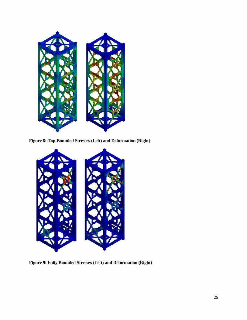
The first goal was to replicate the structural analysis results of the previous MQP team. In order
to do this, we inputted the same data from the GEVS launch profile and ran a simulation on a
simplified version of the Pumpkin structure. We chose to bind the CubeSat on the top and
bottom surfaces in order to come closest to the previous approximation. This presented us with a
similar stress/displacement plots as the previous team, shown in Figure 8. The estimated
displacement of the Pumpkin structure was found to be negligible. The Von-Mises stresses were
also too low to have an effect on the satellite.
The results from this test, however, did not correctly portray the way the CubeSat would
experience forces while inside the P-POD. Because the CubeSat slides into the P-POD along
four rails, there are surfaces along the X and Y faces that are in contact with the inside of the P-
POD which will therefore also experience vibration and forces. In order to account for this, we
applied the simulated vibrations and forces to the rails of the CubeSat as well as the top and
bottom surfaces. This provided us with fairly different looking stress/displacement plots shown
in Figure 9, but in the end the result is the same; the Pumpkin structure will not encounter any
forces strong enough to deform or otherwise fail during launch.
25
Figure 8: Top-Bounded Stresses (Left) and Deformation (Right)
Figure 9: Fully Bounded Stresses (Left) and Deformation (Right)

26
Random Vibration (P-POD 3.4.4)
Each CubeSat shall test, in each axis, the predicted random vibration levels at the P-POD to
NPSCuL mechanical interface. These levels and tolerances are defined in Section 8 [of the P-
POD].
Shock Testing (P-POD 3.4.7)
CubeSat shock testing is not required.
Acoustic Testing (P-POD 3.4.8)
CubeSat acoustic testing is not required.
Sine Vibration (P-POD 3.4.9)
The CubeSat will perform a sine sweep, to the levels in Table 4, before and after each random
vibration test in all three axes to identify possible structural changes.

27
2.2 Current CubeSat Configuration
Current CubeSat Configuration:
(1) Pumpkin 3-Unit Structure
(1) SPHINX-NG Payload
(3) Magnetic Torquers
(1) Magnetometer
(3) Solar Panels
(4) Solar Panel Hinges
(1) GPS Receiver
(4) Coarse Sun Sensor
(1) Fine Sun Sensor
(1) ISIS UHF Antenna
(4) Aluminum Side Panels
(1) P-POD Integration Switch
(1) Vertical Circuit Stack
(1) Vertical Circuit Stack Ring Mount
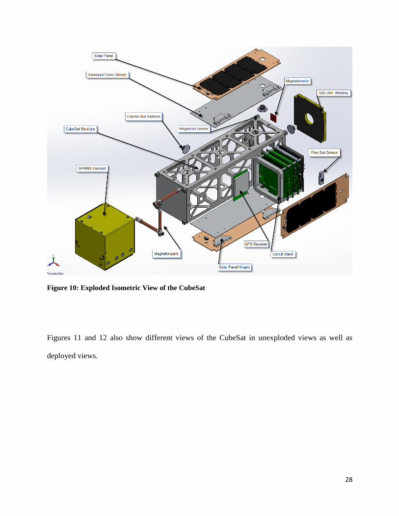
Figure 10 below shows an exploded isometric view of the CubeSat. The view demonstrates the
general idea of where all of the internal components will fit inside of the CubeSat structure itself.
The SPHINX-NG payload will be located in the entire bottom unit of the structure, while the rest
of the components are located in the top two units.
28
Figure 10: Exploded Isometric View of the CubeSat
Figures 11 and 12 also show different views of the CubeSat in unexploded views as well as
deployed views.

29
Figure 11: Stowed (Left)/ Deployed (Right) Satellite Configuration
Figure 12: Faces of CubeSat
+Y +X -Y -X
-Z +Z
30
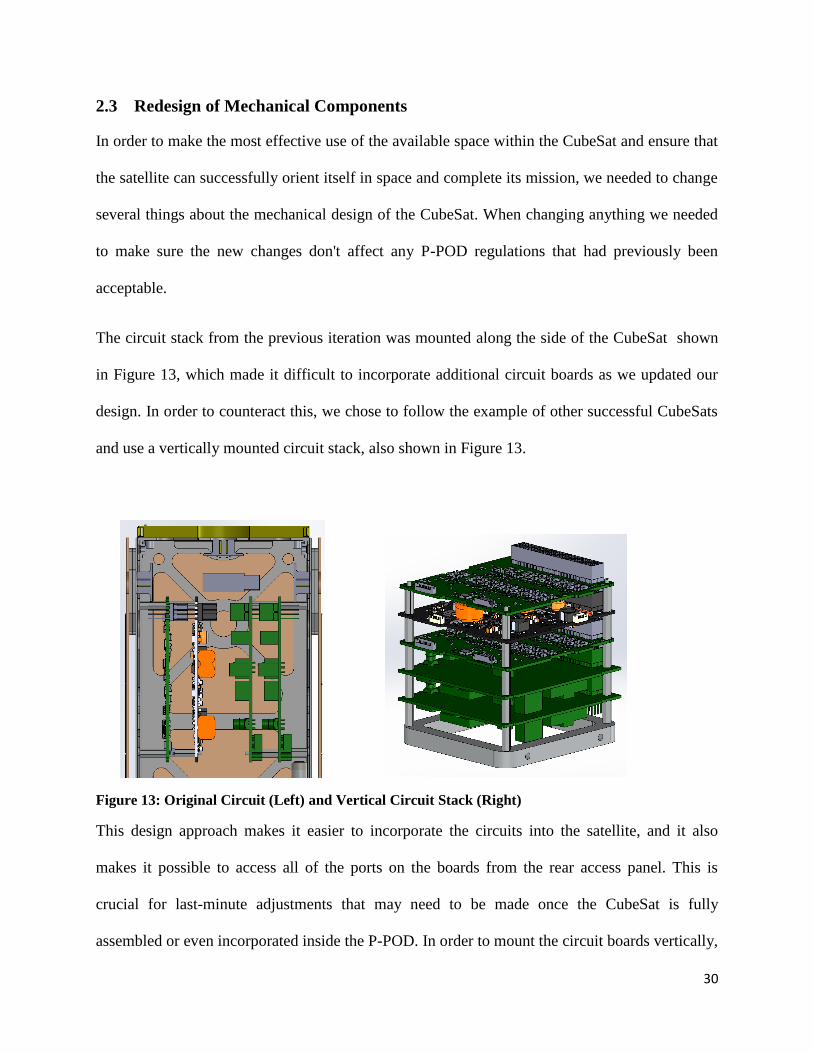
2.3 Redesign of Mechanical Components
In order to make the most effective use of the available space within the CubeSat and ensure that
the satellite can successfully orient itself in space and complete its mission, we needed to change
several things about the mechanical design of the CubeSat. When changing anything we needed
to make sure the new changes don't affect any P-POD regulations that had previously been
acceptable.
The circuit stack from the previous iteration was mounted along the side of the CubeSat shown
in Figure 13, which made it difficult to incorporate additional circuit boards as we updated our
design. In order to counteract this, we chose to follow the example of other successful CubeSats
and use a vertically mounted circuit stack, also shown in Figure 13.
Figure 13: Original Circuit (Left) and Vertical Circuit Stack (Right)
This design approach makes it easier to incorporate the circuits into the satellite, and it also
makes it possible to access all of the ports on the boards from the rear access panel. This is
crucial for last-minute adjustments that may need to be made once the CubeSat is fully
assembled or even incorporated inside the P-POD. In order to mount the circuit boards vertically,

31
we need to manufacture an aluminum ring piece that will act as the base of the stack and be
mounted to the Pumpkin structure. This piece is included in the CAD drawing and can be
manufactured by the CAM machines at WPI.
The initial CubeSat model we received featured three coarse sun sensors as well as one fine sun
sensor. The purpose of these sensors is to let the satellite orient itself so that the SPHINX-NG is
facing the sun. Based on research from the attitude determination and control CubeSat team, the
CubeSat must have at least four coarse sun sensors in addition to the fine sun sensor. This means
that the previous iteration of the satellite needed a new sensor. Unfortunately, the top and bottom
surfaces were occupied by the SPHINX-NG payload and ISIS antenna.
Thanks to research from the thermal analysis CubeSat team, we identified an alternative antenna
that has a hole in its center that is large enough to facilitate a coarse sun sensor on the top of the
CubeSat. With the new antenna, shown in Figure 14, the CubeSat now features the five total sun
sensors required to perform attitude determination.
Figure 14: ISIS Antenna
32
The aluminum plating used on the sides of the CubeSat to equalize thermal loads and
atmospheric charging did not adhere to P-POD requirements. In the first iteration of the CubeSat
CAD drawing, these aluminum plates extended the entire 10 cm width of each of the satellite's
four rectangular faces. This did not leave room for the CubeSat to be integrated into the P-POD,
because the corners of the satellite need to be exposed so that they can slide into the P-POD
chamber.
One of the issues that arose while planning the internal components of the CubeSat was the
availability of the magnetorquers. The previous iteration of the CubeSat had selected a type of
magnetorquer that was no longer available during the time frame of our project. The only option
for us was to choose a different model that had a larger length, which made it a challenge to
incorporate them into the satellite's already limited internal space. The main considerations with
the magnetorquers are 1) they should be close to the central unit of the satellite in order to impart
the most effective moment, and 2) they must be located on orthogonal axes relative to each other
in order to be able to rotate the satellite in roll, pitch, and yaw.
The CAD models for the Clyde Space solar panels were available online, making them fairly
easy to incorporate into our drawing, but the company would not provide any details regarding
the hinges that are used to mount the solar panels to the side of the satellite. In order to help the
thermal analysis team perform their COMSOL simulations, it was important to have a working
model of these hinges so that heat could be transferred between the panel and the satellite body.
The hinge specifications were also necessary in order to ensure that the solar panels do not
extend past the 6.5mm limit specified in the P-POD document. In order to have a working model
of these hinges, we needed to extrapolate the size and location of them from pictures available on
the Clyde Space website. Based on the information available in these images, as well as the flight
33
heritage of the Clyde Space solar panels on other successful CubeSat missions, we believe that
although the hinges may not fully reflect the final design, they adequately represent an expected
final product.

34
2.4 Useful Documentation for Future MQPs
Moving forward we have identified several aspects to assist future CubeSat MQP’s to be able to
smoothly transition to the current state of the mechanical structure as well as to provide them
with easy steps to replicate past analysis. One of the challenges faced this year was making sure
that the CubeSat complied with P-POD Section 3.4.3, CubeSat Structural Survivability. The
section outlines the Qualification and Acceptance values of random vibrations that the CubeSat
must comply with. These random vibration levels represent the vibrations the CubeSat is likely
to encounter during its launch into orbit. The previous MQP team performed this analysis in
SolidWorks yielding positive results that the CubeSat meets these requirements. Our team set out
to make sure that after the modifications recently made, that the CubeSat still complies with the
requirement. The task was difficult to complete because we were unsure of how exactly the
previous MQP completed this analysis in SolidWorks. After much trial and error we were able to
accurately reproduce last year’s results. As the mechanical and structural design continues to
progress in future years, we are creating a tutorial document that allows future teams to be able
to step by step reproduce the Vibration Analysis in SolidWorks. This will save time for future
teams when replicating the analysis.
The P-POD is the primary document analyzed. The document has various areas regarding
mechanical, electrical, and environmental requirements that the CubeSat must comply with. Each
of these requirements entails inspection, analysis, or testing. We have created a document that
allows future teams to be able to easily track their progress with P-POD compliance. The
document clearly outlines every requirement as well as what other documents are referenced and
relevant to each requirement. If a requirement is not yet complete, it provides a set of steps that
the future teams can follow to complete full compliance with the P-POD.

35
Finally, it is important that the future teams have an entirely complete and up-to-date
SolidWorks model of the CubeSat. We have compiled a folder with all of the current parts and
assemblies currently in use. The documents are well labeled and set up in an easy way to
transition for future teams. There are also the past iterations of the CubeSat that are available in
different folders that will allow the team to go back and look at past models if they need too.
36
3 Orbital Analysis
The CubeSat must comply with the orbital debris regulations established in the P-POD and other
applicable documents. This chapter comprises the analysis of the aforementioned documents and
their relevance to the project, in addition to the orbital simulations conducted to establish
compliance with all regulations.
3.1 Poly-Picosatellite Orbital Deployer
A stipulation to launch a CubeSat is that it must fulfill the requirements outlined in the CubeSat
to P-POD Interface Control Document (Cal Poly, 2011). This document, supplied by California
Polytechnic State University in San Luis Obispo, CA, details the prerequisites required to launch
a CubeSat satellite. A requirement the P-POD document declares is the limit for orbit lifetime.
The CubeSat must decay within 25 years or less, as outlined in subsection 1.9.4: Orbital
Lifetime. Chapter 2 of the P-POD lists other applicable documents for the CubeSat program. One
of these documents is the NASA Procedural Requirements for Limiting Orbital Debris (NASA
Procedural Requirements for Limiting Orbital Debris, 2009). The purpose of this document is
to provide requirements to implement NASA’s policy for limiting orbital debris generation.
3.2 NASA Procedural Requirements for Limiting Orbital Debris
The P-POD notes that the NASA Procedural Requirements for Limiting Orbital Debris document
is applicable to the launching of CubeSats into orbit. It clarifies that this document is an
extension of the P-POD and, therefore, requires adherence. In the event that the NASA document
conflicts with the P-POD then the P-POD is to be strictly followed. However, in regards to
orbital debris this is the only document referenced. The P-POD continues in section 2.4 NPR
8715.6A, NASA Procedural Requirements for Limiting Orbital Debris, stating that the NPR

37
document conditions are mandates from the 2006 U.S National Space Policy as well as NASA
Policy Directive requirements (NASA Procedural Requirements for Limiting Orbital Debris,
2009).
When consulting the NPR 8715.6A, the document references 13 additional documents that must
be reviewed for applicability for the CubeSat mission. All additional documents found relevant
to our CubeSat project were evaluated.
The NPR 8715.6A requirements will be verified by processes found in the document NPR
8705.6, Safety and Mission Assurance Audits, Reviews, and Assessments. Further stipulations
include that the project manager for the satellite must submit an Orbital Debris Assessment
Report (ODAR) 30 days before the Safety and Mission Success Review. This allows the Mission
Directorate Associate Administrator to agree with the findings and conclusions of the ODAR. In
addition, the most updated ODAR report must be submitted 45 days before the Critical Design
Review (CDR) is submitted for approval. The CDR is a document demonstrating that the design
of the spacecraft has progressed to a level acceptable for assembly and testing. The Preliminary
Design Review (PDR) is a document submitted prior to the CDR that shows an acceptable risk,
cost benefit analysis, and demonstrates the design is capable of meeting mission requirements.
Another report that must be filed is the End-Of-Mission Plan (EOMP). This details steps the
spacecraft will take once it has completed its mission. The initial EOMP is required for
submission 45 days prior to CDR submission. A pre-launch EOMP report must also be
acquiesced 30 days prior to the predicted launch window.

38
If, for any reason, aspects of the mission fail to meet requirements outlined in the NPR 8715.6A
document then relief requests should be submitted to the Chief/OSMA at the Office of Safety
and Mission Assurance at NASA.
All further requirements from the NPR 8705.6A deemed relevant for our CubeSat can be found
in Appendix B.
3.3 US Government Orbital Debris Mitigation Standard Practices
The U.S Government Orbital Debris Mitigation Standard Practices document is listed in the NPR
8715.6A as an applicable document and contains requirements relevant to our CubeSat mission
(U.S. Government Orbital Debris Mitigation Standard Practices, 2013). This document reviews
the steps required for debris released during the course of the satellite’s lifetime.
All projects must limit debris ejected through normal operations and debris will be reviewed to
be proven necessary if the debris is larger than 5mm and if it will not deorbit within 25 years In
addition every attempt should be made to limit accidental explosions. The risk of accidental
explosions can occur both during and after the mission, therefore, all energy storages must be
depleted once the mission is complete. The project must design the system so as to avoid
collision with man-made and natural objects as well as limiting collisions with debris less than
1cm that can cause the spacecraft to lose control.
When creating the EOMP the project must account for every component of the spacecraft
including the payload. For a spacecraft operating in Low Earth Orbit (LEO) there are three
options for disposal once the mission is concluded. 1) The spacecraft can have an orbit that will
naturally cause it to decay within 25 years into Earth’s atmosphere. If the orbit will not cause
natural decay then a deployable drag device is acceptable to help reduce the altitude. If orbital

39
decay is the selected EOMP then the risk to humans is required to be less than 1 in 10,000. 2)
The spacecraft is transferred to a storage orbit between LEO and GEO. 3) The final option for an
EOMP is retrieving the satellite from orbit directly. Our CubeSat’s EOMP will follow the first
option and have an altitude that allows the satellite to naturally decay in less than 25 years.
3.4 NASA Safety Standard: Guidelines Assessment Procedures for Limiting
Orbital Debris
The NSS 1740.14, NASA Safety Standard: Guidelines and Assessment Procedures for Limiting
Orbital Debris document is an applicable document referenced in the NPR 8715.6A (NSS
1740.14 Guidelines and Assessment Procedures for Limiting Orbital Debris, 1995). This
document provides specific details for assuring the risk of orbital debris for our CubeSat is
minimal.
A required report is the Orbital Debris Assessment (ODAR) which addresses the risk of debris
emitted by the spacecraft either through normal operations, failures, or collisions. The ODAR
also addresses the EOMP and explicitly explains any requirements that the project is unable to
meet. There are five areas of debris the assessment is comprised of, including normal operational
debris, debris generated from explosion or intentional breakup, collision debris, spacecraft
disposal, and the risk of spacecraft elements striking Earth.
For spacecraft operating in LEO, operational debris is considered debris of 1mm or larger
including payload separation, deployment, mission operations, and tethers. In regards to the
CubeSat the ejection of the P-POD will need to be reviewed to determine if the P-POD deployer
itself is categorized as operational debris. The total amount of operational debris 1mm in
diameter or larger will meet two conditions. 1) The total time-area product cannot exceed .1m2
per year. 2) There cannot be more than 100 objects per year ejected by operational debris. This is

40
referred to as the total object-time product. The section for method compliance includes all
equations required to determine the total time-area product and total object-time product for our
CubeSat.
Accidental explosion debris causes the most debris in Earth orbit. In relation to our CubeSat the
possibility for accidental explosions lies with any batteries, thermal control, attitude control, or
control gyroscopes. To combat this risk the spacecraft should include failure modes in the design
and all energy sources should be depleted as soon as they are no longer required for the mission.
The risk of accidental explosions must be less than .0001.
With on-orbit collisions there is the risk of not only emitting debris but also damaging the
spacecraft which can prove fatal for the mission. All collisional debris is considered having
catastrophic potential if it is 10cm in diameter or larger. The guideline for on-orbit collisions
with large objects is considered satisfied if the satellite has a .001 or less probability of collision.
The guideline for on-orbit collisions with small debris is considered fulfilled if the probability is
less than .01. A section for the methods of compliance lists specific equations for calculating the
probability of on-orbit collision. If the CubeSat is found to have a high risk of collision then the
design and altitude will need to be adjusted to meet the guideline.
Due to the high quantity of abandoned spacecraft in orbit there is now a requirement dictating the
amount of time a spacecraft can remain in a particular orbit. All launch vehicles, payloads,
spacecraft, and staging are required to have an EOMP designating a plan for orbital removal.
Most satellites in an orbit of greater than 700 km encounter an issue with meeting the 25 year
orbital limit because they do not naturally decay. Our CubeSat will not face this issue because a
maximum altitude of 640 km was declared for our mission as described in Section 3.1.4.

41
Since our CubeSat is choosing to reenter the atmosphere as part of the EOMP then it must meet
the guidelines for probability of debris surviving reentry. Projects must limit the amount of
survivable debris in an uncontrolled reentry situation. For an uncontrolled reentry disposal the
total debris area cannot surpass 8m2. The section for method compliance details equations for
determining if the satellite will meet this requirement. If it is determined that the guideline is not
met then mitigation includes following a controlled reentry approach, decreasing drag, or using
different material for satellite composition among others.
The final section of the NSS 1740.14 document details explicitly how to set up the PDR and
CDR reports. These reports are critical for following specific processes for receiving approval
for launch of the CubeSat. Both reports are submitted to the Associate Administrator and Office
of Safety and Mission Assurance at NASA. Each party has to approve the document before the
project can continue towards completion.
3.5 NASA Handbook for Limiting Orbital Debris
This handbook contains very detailed explanations about debris environments, preemptive
measures, and mitigation practices (Handbook for Limiting Orbital Debris, 2008). However, the
handbook expires July 30, 2013, therefore the next team to address orbital debris analysis should
review the new handbook for detailed steps and information.
3.6 Technical Probabilistic Risk Assessment Procedures for Safety and Mission
Success for NASA Programs and Projects
The referenced document NPR 8705.5A, Technical Probabilistic Risk Assessment (PRA)
Procedures for Safety and Mission Success for NASA Programs and Projects, is applicable to
“…parties to agreements to the extent specified or referenced in the appropriate contracts, grants,
or agreements (Probabilistic Risk Assessment Procedures Guide for NASA, 2010).” PRA’s are

42
used to assess the risk of various systems. From there it can create an outline to address any
issues that have been identified. Examples can be found in the Probabilistic Assessment
Procedures Guide for NASA Managers and Practitioners.
The PRA report is based around three questions. 1) What can go wrong? 2) How likely is it? 3)
What are the consequences? From these questions the PRA creates different scenarios of
incidents that can occur for the given risk. Using the possible scenarios consequences are
evaluated for a later interpretation of results. If sufficient risks are detected then mitigation
procedures can help identify alternatives for certain mission aspects. In particular, PRA’s are
used to assess risk for project phases. The mitigation that occurs from PRAs is best employed for
important documentation submissions such as the CDR, etc. In conjunction with the PRA, an
Independent Peer Review (IPR) is used as a check and balances system to make sure that the
PRA “…represents the correct risk profile…”
3.7 Notification of Intent to Decommission or Terminate Operating Space Systems
and Terminate Missions
The NPD 8010.3 Notification of Intent to Decommission or Terminate Operating Space Systems
and Terminate Missions establishes the policy for notification of intent to decommission or
terminate operating space systems and terminate missions. As soon as it is determined that a
space system will be decommissioned or that the mission will be terminated it is required to
notify NASA. This document is applicable only to NASA Headquarters and NASA centers. With
regards to our mission, the issue of decommissioning the satellite is already addressed in the
aforementioned NPR 8715.6A

43
3.8 Biological Contamination Control for Outbound and Inbound Planetary
Spacecraft
The NPD 8020.7(Biological Contamination Control for Outbound and Inbound Planetary
Spacecraft, 1999) Biological Contamination Control for Outbound and Inbound Planetary
Spacecraft exposes that NASA does not want the jeopardize the possibility of exploring
celestial bodies with the purpose of finding extraterrestrial life, nor jeopardize the Earth with the
potential hazard of contaminating the planet with extraterrestrial material brought by a returning
spacecraft. This document outlines the responsibilities of NASA centers and contractors for
minimizing and mitigating the risks of interplanetary biological contamination. This NPD is not
relevant for the project since the CubeSat will not be completing an interplanetary mission.
3.9 Risk Management Procedural Requirements
The NPR 8000.4 (Agency Risk Management Procedural Requirements 2008) Risk Management
Procedural Requirements provides a framework that integrates Risk-Informed Decision Making
(RIDM) and Continuous Risk Management (CRM). Risk management is a set of activities aimed
at achieving success by risk-informing the selection of decision alternatives and then managing
the risks associated with the selected alternative. The document addresses the application of
these processes for the execution for safety, technical, cost, and schedule mission procedures
throughout the life cycle of the program. This NPR is applicable for internal operation within
NASA hierarchy. Nonetheless, several concepts and definitions might be useful for future risk
analysis of the CubeSat.
3.10 Planetary Provisions for Robotic Extraterrestrial Missions
This NPR 8010.12 (Planetary Protection Provisions for Robotic Extraterrestrial Missions 2011)
Planetary Provisions for Robotic Extraterrestrial Missions addresses 1) The control of terrestrial

44
microbial contamination associated with robotic space vehicles intended to land, orbit, flyby, or
otherwise encounter extraterrestrial solar system bodies. 2) The control of contamination of the
Earth and the Moon by extraterrestrial material collected and returned by robotic missions.
Section P.2 states that this document is not relevant for terrestrial (Earth-orbit) missions.
3.11 Safety and Mission Assurance Audits, Reviews, and Assessments
The NPR 8705.6 (Safety and Mission Assurance (SMA) Audits, Reviews, and Assessments
2011) Safety and Mission Assurance Audits, Reviews and Assessments establishes the
requirements for conducting audits, reviews and assessments to verify compliance with
applicable federal, state and local safety and health statutes and regulations and NASA Safety
and Mission Assurance requirements. The project managers have to incorporate Safety and
Mission Assurance (SMA) activities into the project, in addition to conducting internal audits
that will have to be made available to the NASA Safety Center. Furthermore, the project
manager will have to conduct Institutional/Facility/Operational (IFO) Safety Audit to verify the
project’s compliance with safety and health statuses, from the federal to the local level.
Additional Quality Audit, Assessment, and Review (QARR); Requirement Flow Down and
SMA Engineering Design Audits and Assessment (REDAA); Safety and Mission Review
(SMSR) processes will have to be conducted as well.
3.12 Technical Report on Space Debris, Scientific and Technical Subcommittee of
the United Nations.
This report is the result of an investigation on orbital debris conducted by the United Nations.
This report addresses three main topics a) the state of knowledge of the earth debris population
from both in situ and terrestrial based measurements; b) the computer model capabilities to
assess debris risks and to forecast the growth of space debris; c) the possible space debris

45
mitigation measures(Technical Report on Space Debris 1999). Sections a) and b) are very
informative and delve into the issue of orbital debris in much more detail than we have done in
this report, section c) addresses most of the mitigation measures that have been considered in the
P-POD and the NPR 8715.6A.
3.13 Orbital Decay Analysis
In P-POD section 1.9.4 it states that the orbital lifetime of the CubeSat must be less than 25
years. This resolution was taken in order to mitigate the effect of space debris and protect the
orbital environment. The orbital debris population has a direct dependence upon the orbital
lifetime of objects positioned in various orbit regimes. Satellites in LEO will be more affected by
atmospheric drag if they are below 700km than satellites in higher orbits. The satellite can exit
the LEO regime in the following ways, 1) De-orbit or maneuver to reduce the orbital lifetime. 2)
Dispose the satellite in an orbit where drag/perturbations will limit the lifetime.
Our predecessor MQP group (Dopart et al., 2012)) chose a sun-synchronous, circular, polar orbit
with a 6:00:00 ascending node with a chosen altitude of 800 km. We had to determine if the
chosen orbit would comply with the orbital debris requirement determined in the P-POD. Using
Systems Toolkit (STK) and the Debris Assessment Software (DAS) developed by NASA we
modeled the CubeSat’s orbital lifetime.
3.14 Systems Toolkit
Our team used Systems Toolkit (STK), simulation software capable of advanced orbital analysis,
to assist in complying with orbital debris and lifetime requirements. The original altitude
estimate was 800 km. To test whether this met requirements we used STK’s Lifetime and Orbit
Wizard tools. Inputting calculated measurements of our CubeSat including a drag area of .055m2,

46
the area exposed to the Sun of .07m2, and a mass of 4kg we were able to declare an accurate
satellite description for simulation.
Last year’s MQP team found specifics of the orbital parameters using STK and we wanted to
remain consistent with their results. In the Orbit Wizard tool we set the orbit to Sun synchronous
with an ascending node of 06:00:00.00. To keep with a circular polar orbit we also adjusted the
orbit properties to the following: Eccentricity, 0; Inclination, 98.44; Argument of Perigee, 0;
RAAN, 142.252; True Anomaly, 0. To see how the orbit lifetime varied with altitude we ran the
calculations from 600-760km in 20km increments.
The documents required by NASA and the P-POD use a NASA developed software called the
Debris Assessment Software (DAS) to run orbital calculations. However, past teams had
developed our orbital parameters using STK which we used for consistency. To make sure
compliance was followed for NASA/P-POD guidelines we ran both STK and DAS calculations
for comparison of orbital lifetimes at different altitudes. Remaining consistent from one software
to another was crucial for accurate results. We used the most current solar flux information,
provided by NASA, for the DAS calculations and kept the default flux model for STK.
3.15 Debris Assessment Software (DAS)
The calculations were performed using the “Orbital Lifetime/Dwell Time” calculator, a
subsection of the Science and Engineering Utilities of DAS. The software requires seven
parameters as the input to calculate the orbital lifetime of the satellite including start year,
perigee altitude, apogee altitude, inclination, right ascension of ascending node, argument of
perigee, and area-to-mass ratio.

47
Start year 2016
Perigee Altitude [km] -
Apogee Altitude [km] -
Inclination [deg] 98.44
R.A. of Ascending Node [deg] 142.252
Argument of Perigee [deg] 0
Area-to-Mass [m^2/kg] 0.01375
The start year we declared as 2016, the earliest year in which the satellite could be launched into
space. The area-to-mass ratio is defined as the cross-sectional area of the satellite divided by its
total mass. In the absence of sophisticated models (i.e. models including tumbling and
stabilization modes) it’s possible to calculate a mean surface area defined as S/2 when averaged
over all possible viewing angles. For a parallel pipe-shaped spacecraft this area is calculated
using equation (1):
[ ]
(1)
We defined and as the areas that are perpendicular to the x, y and z axes, respectively. The
cross-sectional area of the CubeSat is .055m2 with a total mass of 4kg. This flat plate model has
been shown to be accurate to within 20% for tracked objects. We found the remaining
parameters in STK by entering the 06:00:00 ascending node as the input. The parameters are
shown in Table 2 with the perigee and apogee altitudes as the variables used to calculate the
orbital lifetime:
We attempted to calculate the lifetime of the satellite at the chosen orbital altitude of 800 km,
however, DAS did not provide any output because it is unable to calculate any propagation
Table 2: Orbital Parameters

48
Altitude (km) Orbital Lifetime (DAS) [yrs] Orbital Lifetime (STK) [yrs] % Diff.
760 84.18 181.80 115.97%
740 69.60 146.50 110.49%
720 51.73 114.90 122.11%
700 40.58 90.50 123.02%
680 30.86 69.00 123.59%
660 27.06 54.00 99.56%
640 18.91 42.00 122.10%
620 16.83 30.70 82.41%
600 10.49 21.60 105.91%
beyond 100 years. This implies that at an altitude of 800km the satellite will have an orbital
lifetime longer than one century and fail to meet NASA and P-POD requirements. We proceeded
to calculate the lifetime of the CubeSat in the 600 km – 760 km altitude range, using a step of 20
km. The results for both DAS and STK models are shown in Table 3:
Table 3 indicates results obtained from DAS and STK were incongruent with a mean difference
of 112% between both results. After consulting with representatives of Analytical Graphics, Inc.
(AGI)1 and NASA we found the source of our disparity and were able to resolve the issue. The
atmospheric model used in DAS was the Jacchia 1976 Standard Model. In STK, we were
originally operating under the Jacchia 1970 Lifetime Model. Since we were unable to alter the
DAS atmospheric model we changed STK’s to match the DAS model. The results can be seen in
Table 4.
1 1
AGI is the developer of the STK software package.
Table 3: Orbital Lifetime Original Results

49
Altitude (km) Orbital Lifetime (DAS) [yrs] Orbital Lifetime (STK) [yrs] %Diff.
760 84.18 111.4 32.34%
740 69.60 88.1 26.58%
720 51.73 68.8 33.00%
700 40.58 53.3 31.35%
680 30.86 40.8 32.21%
660 27.06 30.9 14.19%
640 18.91 23.3 23.22%
620 16.83 17.3 2.79%
600 10.49 12.8 22.02%
There was a significant reduction in the discrepancy between the results obtained from DAS and
STK. After matching the atmospheric models the mean percentage difference was 24%, as
opposed to the 112% obtained before. A representative from NASA communicated that results
typically differ by an average of 10-20%. DAS uses historical values of the solar flux archived
by the U.S. National Oceanic and Atmospheric Administration’s (NOAA) Space Environment
Center (SEC). Furthermore, for calculations beyond the near term, a curve-fit technique using
sixth-order sine and cosine terms was performed to fit historical daily solar flux values from
1947 through September 2005 (4). This polynomial fit is then used to generate future predictions
of the solar flux. On the other hand, the solar flux model used in STK is based on the solar model
developed by Kenneth Schatten and Dean Pesnell of the NASA Goddard Space Flight Center.
Since we were not able to duplicate the solar flux models in both software we considered the
extra 4% error marginal. The results of this analysis are shown in figure 15.
For orbital lifetime requirements our team found that any altitude below 640km would yield an
orbital decay time of less than 25 years. This was confirmed by both DAS and STK. Our closest
results were at 620km with DAS generating a lifetime of 16.83 years and STK yielding 17.3
years, a percentage difference of 2.79.
Table 4: Orbital Lifetime, 2nd
Iteration

50
Figure 15: Orbital History for Satellite at 640 km altitude. Obtained from DAS.

51
4 Analysis of Electromagnetic Interference Due to Magnetic Torquers
Electromagnetic interference affects the survivability and operation of the CubeSat along with its
payload, the SPHINX-NG. When electronic components induce an electromagnetic field they
may affect the operation of other devices. The previous MQP group (Dopart et al., 2012)
determined the magnetic flux of the magnetic torquers was strong enough to interfere with the
readings of the magnetometer. Although magnetic torquers are designed for low force torques,
the magnetic field created will disrupt the function of the magnetometer. The magnetic torquers
are similar to simple solenoids in that they produce induced magnetic fluxes. The P-POD
document does not list requirements for the prevention, testing, or analysis of the
electromagnetic interference. The COMSOL Multiphysics software was used to determine if
action is needed to minimize the interference magnetic torquers can have on the magnetometer.
4.1 Magnetometer on the WPI CubeSat
A magnetometer is an instrument used to measure the Earth’s ambient magnetic field, in terms of
magnetic flux density, and read the direction the magnetic field flows. The magnetometer also
measures the strength of magnetic fields. Magnetic flux density is the strength of a magnetic
field or magnetic flux in an area perpendicular to the direction of a magnetic flow (Electricity
and Magnetism, 2013). The magnetic field the Earth creates induced measurable magnetic
disturbances in the atmosphere that allows the magnetometer to measure the magnetic field and
communicate with the magnetic torquers to accurately control the pitch, yaw, and roll
maneuvers. Figure 16 depicts the directions of these motions with respect to the Earth. It takes
constant measurements because the Earth’s magnetic field is always changing depending on
latitude and longitude, but has an average value of 0.5 Gauss. The field also fluctuates depending

52
on location and intensity of solar winds. The CubeSat’s magnetometer is the Honeywell
HMC5883L. It is relatively small measuring 17.78x17.78x0.9 millimeters, light weight at 18
milligrams, and has a 1-2 degree heading accuracy. The magnetometer has an offset range of
only ±8 Gauss before the disturbance from the magnetic torquers make the readings of the
magnetometer too inaccurate. The magnetometer takes readings for about 6 milliseconds at a
time. These quick ambient readings can be used to calculate which magnetic torquer to use to
orient the CubeSat in different positions.
Figure 16: Orientation of Satellite with Respect to Earth
4.2 Magnetic Torquers
Magnetic torquers are solenoids. As the current flows through the magnetic torquers, an induced
magnetic field creates torque against the earth’s magnetic field, controlling the Cubesat’s
orientation. A magnetic torquer’s operational purpose is for attitude control on three axes of
rotation: roll, pitch, and yaw (Magnetic Torquers, 2013). These are the x, y, and z directions
respectively. Magnetic torquers are coils of uniform wire, usually made out of copper, that
generate a current when a voltage is applied. This current produces a magnetic dipole. The
dipole’s strength and direction depend on the amount of current and the direction the current is
flowing, the number of times the wire is wrapped into a coil, and the length of the wire per coil.
The dipole that is created interacts with the Earth’s magnetic field. The magnetic field generated

53
by the coil aligns itself opposite the direction of the B field of the Earth Magnetic Torquers).
Using the reading from the magnetometer, the on-board computer (OBC) knows which of the
three magnetic torquer to use to orient the CubeSat into the new desired position. The mission
limitations indicate magnetic torquers as the best option for attitude control. The PPOD
Document forbids the use of an onboard propulsion system to prevent any potential damage to
the launch vehicle and other CubeSats. The CubeSat is small enough that magnetic torquers,
typically used for small adjustments in attitude, can provide sufficient control for the entire
satellite. One issue with the use of magnetic torquers is that the produced torque is low, so quick
adjustments are not possible.
The magnetorquers used for this CubeSat mission are the ZARM Technik AG MTO 5.1 Power
Optimized. Figure 17 depicts the different models of ZARM technik magnetic torquers. Previous
MQP group (Dopart et al., 2012) used the ZARM Technik AG MTO 2.1 but the company no
longer supplies this model. The 5.1 Power Optimized torquer is bigger than the 2.1 making it 90
mm in length and9 mm in diameter, with a mass of about 30 grams. As a bonus, the 5.1 uses less
power and creates a stronger magnetic moment than the 2.1. (Magnetic Torquers for Micro-
Satellites, 2013)
Figure 17: ZARM Technik Magnetic Torquers

54
4.3 Analytical Modeling the Induced Field from a Solenoid
Since the magnetorquers chosen last year are no longer available, new mathematical models
were required to determine the strength of the 5.1 magnetorquers. The Resultant force of the
magnetic torque and magnetic field vector is shown in Figure 18. Using the Lorentz Force Law
the following equation was found and the force of the torque calculated using: (Electricity and
Magnetism, 2013)
(2)
(3)
(4)
Figure 18: Force Vector as a Result from Magnetic Torquer
F is the force of the torque created, I is the current, L is the length of wire for a unit of coil or
number of turns multiplied by area of coil, Θ is the angle between the dipole and B field, and B
is the magnetic field of the Earth (Magnetic Torquers, 2013). The B field of a coil is given by:
(
√ (
)
√ (
)
)
(5)

55
The permittivity of free space is µ = 4π10-7
H/m , Ko is the surface current of the coil (A/m), d is
the length of the coil (m), r is the radius of the coil (m), z is the distance from the center of the
coil in the z axis (m) , I (A) is the current of the coil, and N represents the number of turns of
coil. The surface current Ko is given by:
(6)
With N= 142,900 turns, L= 90 mm, I=55 mA, Ko = 87,327.82 A/m and the magnetic field at the
center of the solenoid, z=0 m, is estimated to be B (z=0) =0.055 Tesla (or 550 Gauss). The
magnetic field at the end the solenoid, is B (z=0.045) = 0.1096 Tesla (or 1096 Gauss). The
previous MQP group (Dopart et al., 2012) using the ZARM 2.1 found the maximum B field
within the solenoid to be 0.1025 Tesla (or 1025 Gauss).
4.4 Simulation of a Single Magnetic Torquer in Free Space
In addition to the analytical model, the magnetic field of a magnetic torquer is simulated using
COMSOL. This program is capable of simulating the magnetic field generated by a multi-turn
electromagnetic coil. We applied the AC/DC module for the physics used for all the
computations. A cylinder with the dimensions of the magnetorquer was input into the system,
along with important data including the coil current, the cross-sectional area of the wire, and the
number of turns. The severity of magnetic flux density is represented by a color scale and several
arrows of varying size as shown in Figure 19. Figure 20 displays the magnetic field emitted by
the magnetorquer in the form of red streamlines.
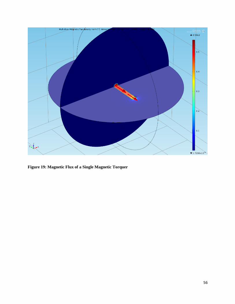
56
Figure 19: Magnetic Flux of a Single Magnetic Torquer

57
Figure 20: Streamlines of the Magnetic Field of a Single Magnetic Torquer
4.5 Simulation of Three Magnetic Torquers
Using COMSOL our team placed three cylinders in orthogonal positions to represent three
magnetic torquers inside an aluminum rectangular prism representing the pumpkin structure.
Inputting the same variables as the single magnetic torquer model, the magnetic field and the
magnetic flux for the three magnetic torquers were calculated, these results are displayed in
Figure 21. In Figure 22, COMSOL showed that the magnetic torquers produce a maximum field
of 1167.88 Gauss and a minimum field of 8.375x10⁻⁸
Gauss in outer edge of the free space
sphere. Because all three magnetic torquers will not be operating at the same time, this is a worst
case scenario. When all three magnetic torquers are working at the same time an accurate
magnitude of the field is not attainable because the fields of each torquer interfere with one
another.

58
Figure 21: Mutlislice of Magnetic Flux Normal of Three Magnetic Torquers
Figure 22: Streamlines of the Magnetic Field Due to Three Magnetic Torquers

59
4.6 Permeability of the Pumpkin Structure
In order for the magnetic torquers to operate properly the B field of the earth needs to reach the
magnetometer and magnetic torquers without interference. Using COMSOL, different materials
were analyzed in place of the satellite structure to see the differences as the relative permeability
increases. When using a material with a high relative permeability of 50000, the magnetic B field
of the Earth was deflected around the structure rather than through the structure as depicted in
Figure 23.
Figure 23: B Field Acting on Structure with Relative Permeability of 50000

60
The magnetometer needs the B field in order to determine which direction the magnetic torquers
need to apply a torque to correct the CubeSat’s attitude. If the B field of the earth cannot
penetrate the CubeSat structure, the magnetic torquers will not function properly. The aluminum
5052 H32 material used for the Pumpkin structure has a relative permeability of approximately
1.0. The aluminum structure allowed the field to pass through the structure with no deflections as
shown in Figure 24.
Figure 24: B Field Acting on Structure with Relative Permeability of 1.0

61
5 Conclusions and Recommendations
5.1 Finalize All Internal Components and Locations Within the CubeSat
The current SolidWorks model is close to the finalized model that will be used. Although the
CubeSat may be deemed finalized at one point, there is the chance that some of the COTS items
may no longer be available as seen recently with the magnetorquers, and the groups should be
ready to accommodate for unforeseen changes. The final inspection, analysis, and testing will all
need to be performed once the entire CubeSat design has been finalized in order to make sure
that it complies with all P-POD requirements.
5.2 Complete Compliance Between the CubeSat Structure and the SPHINX-NG
Payload
There are a few notable issues that arose during our mechanical redesign regarding the SPHINX-
NG payload. Primarily, the SPHINX-NG cannot fit inside the Pumpkin structure due to an
interference with the previously-unknown metal piece used to fasten the removable face to the
rest of the structure. This interference is shown in figure 23. Additionally, with the decision to
invert the structure so that the integration switch is opposite the SPHINX-NG unit, we found that
the optical sensors on the SPHINX-NG no longer lined up with the holes on the Pumpkin
structure, shown in figure 24. This means that the SPHINX-NG cannot perform the X-Ray
spectrometry that it was designed to perform unless its sensors are reoriented or the Pumpkin
structure is cut. Another current issue is the problem with the SPHINX-NG radiator being
located on the rails of the CubeSat structure, as seen in figure 25, which will prevent it from
properly being loaded into the P-POD itself. These are critical issues that must be addressed in
order to ensure that the internal positioning of each device can accurately be finalized.

62
Figure 25: Overlap Between SPHINX-NG and Pumpkin Structure
Figure 26: SPHINX-NG Sun Sensors Obstructed by Skeleton
Figure 27: SPHINX-NG Radiator Interfering With CubeSat Rails
63
5.3 Acquire an Accurate and Complete SolidWorks Model of the Solar Panel
Hinges and Update the CubeSat SolidWorks Model
The current hinges incorporated in the current CubeSat model were extrapolated from images
sent from Clyde Space. Moving forward it is important to have accurately dimensioned hinges to
ensure that the solar panels do not interfere with the P-POD when the CubeSat is integrated into
the P-POD.
5.4 Determine How the Solar Panels Will Deploy
P-POD Sections 3.1.1 and 3.2.5.2 require that the solar panels be self-contained by the CubeSat
and not in contact with the P-POD itself, and that they deploy minimum after 30 minutes from
being ejected from the P-POD. We understand that the deployment is likely performed by a
hotwire switch, but it has yet to be fully determined what the requirements for this switch are, as
well as the spring constant with which the panels deploy.
5.5 Complete Remaining P-POD Requirements
The CubeSat must comply with every single P-POD requirement in order to be sent into space.
All of the inspection, analysis, and testing must be completed. Progress has already been made to
comply with these requirements.
5.6 Generate the Correct Wiring From Each Internal Device to Accurately Reflect
the Entire Final CubeSat
In order to finalize the CubeSat model, the wiring that will go from each device should be
represented in the model. This will allow future groups to be able to determine a more accurate
moment of inertia. It will also allow them to determine if there will be any complications with

64
physical space or other constraints that would prevent the wires from properly connecting
throughout the CubeSat. The task will require the help of the Thermal and Power MQP team
who is currently determining how the devices will be wired to one another.
5.7 Magnetic Shielding for the Magnetometer
Since the magnetic field from the magnetic torquers will interfere with the magnetometer we
have looked into possible solutions to this problem. One option is placing the magnetometer
outside the CubeSat, but this could interfere with the P-POD dimensional constraints and could
pose a risk to the component exposed to a space environment. Previous CubeSat MQP teams
have looked into placing the magnetic torquers on a boom so that they are distant from the
magnetometer. However, this also conflicts with the P-POD and mission requirements restricting
the use of booms.
A magnetic shielding material could be used to protect the magnetometer from the magnetic field
of the magnetic torquer, while using a small amount of space inside CubeSat. The shielding
would be made out of mu metals which are specially designed materials that have strong
magnetic shielding properties and used in industries such as aviation, medical, and education
(MuMetal). Another option is bi-axially oriented polyethylene terephthalate (Mylar) which can
be sold in thin sheets kind of like aluminum foil (Magnetic Field Shielding, 2013). A thin
magnetically shielding sheet would have low cost and fit within the limited space available in the
CubeSat.
While it is possible to shield the magnetometer from the magnetic torquers, this would also
shield the magnetometer from the magnetic field of the Earth. If the magnetometer does not
accurately measure the Earth’s B field, the magnetic torquers will not have the correct data to

65
control the attitude of the satellite. The only way to prevent the magnetometer from reading the
field generated by the magnetic torquers, while allowing the ambient B field to reach the
magnetometer, is to ensure that the magnetometer and the magnetic torquers are never
functioning at the same time.

66
6 Appendix A: Foreign CubeSat Missions
Name Type Mission Organization Country Launcher Launch Date
Jugnu 3U Technology demonstration and remote sensing ITT Kanpur India PSLV-CA October 2011
Xatcobeo 1U Demonstrate software-defined radio and solar panel deployment University of Vigo Spain Vega February
2012
Robusta 1U Test and evaluate radiation effects on bipolar transistor components Montpellier 2
University
France Vega February
2012
e-st@r 1U Demonstration of an active 3-axis attitude determination and control
system
Politecnico di
Torino
Italy Vega February
2012
Goliat 1U Imaging of earth and measurement of radiation and micrometeoroid flux University of
Bucharest
Romania Vega February
2012
PW-Sat 1U Test deployable atmospheric drag augmentation device Warsaw University
of Technology
Poland Vega February
2012
MaSat-1 1U Demonstrate various spacecraft avionics Budapest
University of
Technology and
Economics
Hungary Vega February
2012
UniCubeSat
GG
1U Study the gravity gradient Sapienza
University of
Rome
Italy Vega February
2012
F-1 1U Test a 3-axis magnetometer FPT University Vietnam H-IIB July 2012
Raiko 2U Earth imaging, testing of a star sensor, orbit determination by Doppler
frequency measurement of Ku-band beacon radio wave
Wakayama
University
Japan H-IIB July 2012
FITSAT-1 1U Demonstration of a high-speed transmission module. Visible light
communication experiment by high power LED
Fukuoka Institute
of Technology
Japan H-IIB July 2012
WE WISH 1U Demonstration of an ultra-small infrared camera Meisei Corporation Japan H-IIB July 2012
PUC-P-SAT-
1
1U Technology demonstration Pontificia
Universidad
Catolica del Peru
Peru - 2012
(planned)
CHASQUI-1 1U Technology demonstration, earth imaging National
University of
Engineering
Peru - 2012
(planned)

67
Name Type Mission Organization Country Launcher Launch Date
Jugnu 3U Technology demonstration and remote sensing ITT Kanpur India PSLV-CA October 2011
Xatcobeo 1U Demonstrate software-defined radio and solar panel deployment University of Vigo Spain Vega February
2012
Robusta 1U Test and evaluate radiation effects on bipolar transistor components Montpellier 2
University
France Vega February
2012
e-st@r 1U Demonstration of an active 3-axis attitude determination and control
system
Politecnico di
Torino
Italy Vega February
2012
Goliat 1U Imaging of earth and measurement of radiation and micrometeoroid flux University of
Bucharest
Romania Vega February
2012
PW-Sat 1U Test deployable atmospheric drag augmentation device Warsaw University
of Technology
Poland Vega February
2012
MaSat-1 1U Demonstrate various spacecraft avionics Budapest
University of
Technology and
Economics
Hungary Vega February
2012
UniCubeSat
GG
1U Study the gravity gradient Sapienza
University of
Rome
Italy Vega February
2012
F-1 1U Test a 3-axis magnetometer FPT University Vietnam H-IIB July 2012
Raiko 2U Earth imaging, testing of a star sensor, orbit determination by Doppler
frequency measurement of Ku-band beacon radio wave
Wakayama
University
Japan H-IIB July 2012
FITSAT-1 1U Demonstration of a high-speed transmission module. Visible light
communication experiment by high power LED
Fukuoka Institute
of Technology
Japan H-IIB July 2012
WE WISH 1U Demonstration of an ultra-small infrared camera Meisei Corporation Japan H-IIB July 2012
PUC-P-SAT-
1
1U Technology demonstration Pontificia
Universidad
Catolica del Peru
Peru - 2012
(planned)
CHASQUI-1 1U Technology demonstration, earth imaging National
University of
Engineering
Peru - 2012
(planned)

68
7 Appendix B: Reference Documents
NASA Procedural Requirements for Limiting Orbital Debris
NPR 8715.6A
Relevant Documents
U.S Government Orbital Debris Mitigation Standard Practices
NPD 8700.1 NASA Policy for Safety and Mission Success
NASA Safety Standard (NSS) 1740.14 Guidelines and Assessment Procedures for Limiting Orbital Debris
NASA Standard (NASA-STD) 8719.14, Process for Limiting Orbital Debris
NASA-Handbook (NHBK) 8719.14, Handbook for Limiting Orbital Debris
NPD 8010.3, Notification of Intent to Decommission or Terminate Operating Space Systems and Terminate Missions
NPR 7120.5 NASA Space Flight Program and Project Management Requirements
NPR 8000.4 Risk Management Procedural Requirements
NPR 8705.5 Probabilistic Risk Assessment Procedures for NASA Programs and Projects
NPR 8705.6 Safety and Mission Assurance Audits, Reviews, and Assessments
NPR 8715.3 NASA General Safety Program Requirements
Technical Report on Space Debris, Scientific and Technical Subcommittee of the United Nations
Committee of the Peaceful Uses of Outer Space
IADC-02-01, Space Debris Mitigation Guidelines, Inter-Agency Space Debris Coordination
NPR 8715.6A
P.5Complaince with the requirements containted in this NPR will be verified through processes contained in
the NPR 8705.6, Safety and Mission Assurance Audits, Reviews, and Assessments.
2.1.2 Project Manager must include relevant design requirements as applicable in paragrah P.2.4
2.1.5 Project Manager must submit abbreviated ODAR to non-NASA launching/lead agency as part of the
delivery of hardware data package covering spacecraft portions being developed/integrated by NASA
organization as permitted in ITAR.
2.1.5.b Shall submit final ODAR 30 days prior to SMSR review and shall get MDAA concurrence.
2.2.1.1 Project Manager must assess mission for complaince with NRP 8715.6A, NSS 1740.14 for generation of OD
during entire mission.
2.2.1.4 PDR/CDR versions of ODAR should be submitted electronically but retain the option to submit by paper.
Final ODAR must be submitted in both paper and electronics forms.
2.2.1.8 Project Manager must submit updated mission ODAR no later than 45 days before the mission CDR.
2.2.1.9 Project Manager must submit final mission ODAR no later than 30 days before opening launch window.
2.2.2.1 Project Manager must refer mission compliance for appropriate disposal for portion run by NASA to NPR
8715.6A and NSS 1740.14
2.2.2.3 Project Manager must submit each draft of the EOMP to Chief/OSMA, AA/SOMD, and MDAA for review.
2.2.2.7 MDAA must approve both prelaunch and final EOMP after they have been concurred by Chief/OSMA.
2.2.2.8 Project Manager must submit initial draft of the EOMP no later than 45 days before submitting the CDR.
2.2.2.9
Project Manager must submit the prelaunch EOMP no later than 30 days before opening launch window.
2.2.4.2 If mission does not meet any of the stated requirements in NPR 8715.6A than a request for relief must be
submitted to Chief/OSMA.
A) Requests for relief that are relevant to mission post launch must be stated in final EOMP.
2.2.4.3 If there are repetitive noncompliances then a single report can be submitted to the Chief/OSMA
3.2.7 The Program Manager must inform the MDAA who will report to the Chief/OSMA within 96 hours if there
is an event on the spacecraft in LEO.
A) "The spacecraft no longer serves any useful function or purpose."
B) "Redundancy or other key functionality is lost in the end-of-life disposal or deorbit system."
3.2.8 The MDAA has one week to inform the Chief/OSMA if either of the following occurs:
A) "The nominal propellant level required for controlled deorbit or disposal manuevers is projected to
occur in six months."
B) "Insufficient fuel remains onboard the spacecraft to perform all planned EOM manuevers plus a 15
percent fuel margin."
3.2.10 The Program Manager must inform the DOD's Space Surveillance Network if the satellite plans on
performing manuevers that will change the satellite orbit by more than 1km.
3.3.1.2 If the satellite is going to reenter the atmosphere then it must be passivated prior to deorbit.
3.3.1.3 The Program Manager must update the EOMP if any changes occur that would alter the spacecrafts ability
to passivate.
3.3.1.4 Passivation includes actions required to prevent spacecraft breakup.
3.3.1.5 Systems will be analyzed if passivation is required, including:
A) Electrical Systems
B) Mechanical Pressure Systems
C) Chemical Systems
D) Mechanical Systems
3.3.2 The following are requirements for EOM of spacecraft reentering Earth's atmosphere:
3.3.2.1 If the spacecraft is under 2000km then it must manuever to an orbit that will allow it to compile with the
25 year orbital limit.
3.3.2.2 The MDAA will alert correct authorities one week prior to a spacecraft controlled reentry.
3.3.2.3 Passivation must be sufficient enough so that internal energy does not breakup the spacecraft.
3.3.2.4 "The Program/Project Manager shall include evaluation of the long-term pertubations on, and the future
trajectories of, orbital spacecraft and launch vehicle stages in the EOMP."
APPENDIX ATerms and Definitions
APPENDIX BAcronyms

69
NASA Procedural Requirements for Limiting Orbital Debris
NPR 8715.6A
Relevant Documents
U.S Government Orbital Debris Mitigation Standard Practices
NPD 8700.1 NASA Policy for Safety and Mission Success
NASA Safety Standard (NSS) 1740.14 Guidelines and Assessment Procedures for Limiting Orbital Debris
NASA Standard (NASA-STD) 8719.14, Process for Limiting Orbital Debris
NASA-Handbook (NHBK) 8719.14, Handbook for Limiting Orbital Debris
NPD 8010.3, Notification of Intent to Decommission or Terminate Operating Space Systems and Terminate Missions
NPR 7120.5 NASA Space Flight Program and Project Management Requirements
NPR 8000.4 Risk Management Procedural Requirements
NPR 8705.5 Probabilistic Risk Assessment Procedures for NASA Programs and Projects
NPR 8705.6 Safety and Mission Assurance Audits, Reviews, and Assessments
NPR 8715.3 NASA General Safety Program Requirements
Technical Report on Space Debris, Scientific and Technical Subcommittee of the United Nations
Committee of the Peaceful Uses of Outer Space
IADC-02-01, Space Debris Mitigation Guidelines, Inter-Agency Space Debris Coordination
NPR 8715.6A
P.5Complaince with the requirements containted in this NPR will be verified through processes contained in
the NPR 8705.6, Safety and Mission Assurance Audits, Reviews, and Assessments.
2.1.2 Project Manager must include relevant design requirements as applicable in paragrah P.2.4
2.1.5 Project Manager must submit abbreviated ODAR to non-NASA launching/lead agency as part of the
delivery of hardware data package covering spacecraft portions being developed/integrated by NASA
organization as permitted in ITAR.
2.1.5.b Shall submit final ODAR 30 days prior to SMSR review and shall get MDAA concurrence.
2.2.1.1 Project Manager must assess mission for complaince with NRP 8715.6A, NSS 1740.14 for generation of OD
during entire mission.
2.2.1.4 PDR/CDR versions of ODAR should be submitted electronically but retain the option to submit by paper.
Final ODAR must be submitted in both paper and electronics forms.
2.2.1.8 Project Manager must submit updated mission ODAR no later than 45 days before the mission CDR.
2.2.1.9 Project Manager must submit final mission ODAR no later than 30 days before opening launch window.
2.2.2.1 Project Manager must refer mission compliance for appropriate disposal for portion run by NASA to NPR
8715.6A and NSS 1740.14
2.2.2.3 Project Manager must submit each draft of the EOMP to Chief/OSMA, AA/SOMD, and MDAA for review.
2.2.2.7 MDAA must approve both prelaunch and final EOMP after they have been concurred by Chief/OSMA.
2.2.2.8 Project Manager must submit initial draft of the EOMP no later than 45 days before submitting the CDR.
2.2.2.9
Project Manager must submit the prelaunch EOMP no later than 30 days before opening launch window.
2.2.4.2 If mission does not meet any of the stated requirements in NPR 8715.6A than a request for relief must be
submitted to Chief/OSMA.
A) Requests for relief that are relevant to mission post launch must be stated in final EOMP.
2.2.4.3 If there are repetitive noncompliances then a single report can be submitted to the Chief/OSMA
3.2.7 The Program Manager must inform the MDAA who will report to the Chief/OSMA within 96 hours if there
is an event on the spacecraft in LEO.
A) "The spacecraft no longer serves any useful function or purpose."
B) "Redundancy or other key functionality is lost in the end-of-life disposal or deorbit system."
3.2.8 The MDAA has one week to inform the Chief/OSMA if either of the following occurs:
A) "The nominal propellant level required for controlled deorbit or disposal manuevers is projected to
occur in six months."
B) "Insufficient fuel remains onboard the spacecraft to perform all planned EOM manuevers plus a 15
percent fuel margin."
3.2.10 The Program Manager must inform the DOD's Space Surveillance Network if the satellite plans on
performing manuevers that will change the satellite orbit by more than 1km.
3.3.1.2 If the satellite is going to reenter the atmosphere then it must be passivated prior to deorbit.
3.3.1.3 The Program Manager must update the EOMP if any changes occur that would alter the spacecrafts ability
to passivate.
3.3.1.4 Passivation includes actions required to prevent spacecraft breakup.
3.3.1.5 Systems will be analyzed if passivation is required, including:
A) Electrical Systems
B) Mechanical Pressure Systems
C) Chemical Systems
D) Mechanical Systems
3.3.2 The following are requirements for EOM of spacecraft reentering Earth's atmosphere:
3.3.2.1 If the spacecraft is under 2000km then it must manuever to an orbit that will allow it to compile with the
25 year orbital limit.
3.3.2.2 The MDAA will alert correct authorities one week prior to a spacecraft controlled reentry.
3.3.2.3 Passivation must be sufficient enough so that internal energy does not breakup the spacecraft.
3.3.2.4 "The Program/Project Manager shall include evaluation of the long-term pertubations on, and the future
trajectories of, orbital spacecraft and launch vehicle stages in the EOMP."
APPENDIX ATerms and Definitions
APPENDIX BAcronyms

70
NASA Safety Standard: Guidelines and Assessment Procedures for Limiting Orbital Debris
NSS 1740.14
1.1 Document provides analysis for limiting the creation of debris, assessing the risk of collision with current debris, and assessing
risk of spacecraft debris hitting Earth
1.2.0 Orbital Debris Assessment (ODA) must address debris creation by normal operations as well as failure conditions and collosions.
In addition must also address End-of-mission-plan (EOMP).
1.3.0 If guidelines are not met due to cost or mission requirements then they must be explicitly stated in ODA with justification.
2 Debris assessment covers five areas: debris from normal operations, debris from explosions/intentional breakup, debris from
collision, disposal of spacecraft after mission, and spacecraft components impacting Earth.
2.2 Performing Debris Assessments: Table 2-1 for issues and guideline descriptions
3 Operational Debris is considered 1mm or larger for LEO and includes staging/payload seperation, deployment, mission
operations, tethers.
General Policy Objective: Control of Debris Released During Normal Operations
3.1.0 Operational Debris in LEO: total amount of 1mm diameter or greater must meet 2 conditions
A "Total area-time product should be no larger than .1m^2-yr." "Area-time product is the sum over all operational debris of the
debris cross-sectional area multiplied by the total time spent below 200km during orbit lifetime."
B "Total object-time product should be no larger than 100 object-yr. The object-time product is the sum over all operational debris
of the total time spent below 2000 km altitude during the orbit lifetime of each debris object"
*tethers are included in operational debris
Rationale for Guidelines
3.1.0A The amount of debris released should not pose as a large risk of collision with other objects in orbit. Typically the average cross -
sectional area for spacecraft is roughly 10m^2 with a lifetime of 3 yrs. Therefore, the area-time is on average 30m^2 product. This
creates a guideline between .1-1m^2-yr yields probability of collision from 1/30-1/300. A product of .1 was adopted based on
overall spacecraft consideration.
3.1.B Based on historical information it was determined that an acceptable level of risk was <10^6 for debris damaging other
spacecraft. A 100 object-yr value was chosen because it has a probability of damage to other craft of 10^-6.
Method to Assess Compliance with the Guidelines
Lists the equations required to determine the object-time product and total area-time product. Must use equations listed in this
section to determine if Cubesat is within the requirements for these products.
Summary of Debris Mitigation Measures
If project does not meet guideline limits then mitigation practices must be taken. Investigate release of debris in parallel with
peak solar activity, release debris with lower perigee altitudes to decrease debris lifetime, release debris when lunar/solar
disturbances will reduce debris life, limit debris by changing design or procedures.
4 Debris generated by explosions are the biggest contributer of orbital debris.
4.1.0 Accidental explosions include spent upper stages, structural failure of pressurized volumes including batteries, thermal control,
attitude control, propulsion systems, and control gyroscopes.
General Policy Objective: Control of Debris Generated by Accidnetal Explosions
4.1.0 In designing spacecraft to limit accidental explosion failure modes and effects analyses need to be implemented.
4.2.0 As soon as energy sources are not needed for mission requirements they must be immediately depleted.
Rationale for Guidelines
Spacecraft have a less than 10^-6 probability of colliding with explosion fragments of less than 1mm because the maximum
probability of accidental explosion must be .0001.
Method to Assess Compliance with the Guidelines
4.1.0 Eliminate stored energy source
General Policy Objective: Control of Debris Generated by Intentional Breakups
5 Assessment of Debris Generated by On-Orbit Collisions
Spacecraft can create debris by collision with other objects or can become fragmented debris if it collides with current space
junk. These collisions could cause the spacecraft to be unable to follow is EOMP. If the spacecraft is intact it poses a small risk but
if fragmented it drastically increases the probability. Debris 10cm in diameter or larger is assumed to have the possibility of
creating catastrophic problems. The spacecraft must follow its EOMP or else it becomes a source of debris.
General Policy Objective: Limit the Generation of Orbital Debris From On-Orbit Collisions
5.1.0 For collisions with large objects, if the probability is less than .001 then the guideline can be considered met.
5.2.0 The guideline is considered met when the probability of debris collision is .01 or less. This will ensure that the EOMP can be
completed.
Rationale For Guidelines
This guideline is for the average spacecraft with average size and lifetime in circular orbit. Average collision is collision
probability over altitude.
Methods to Assess Compliance with the Guidelines
5.1.0 Collisions with Large Objects During Mission Operations. Equations for calculating proability in LEO.
5.2.0 Collisions with Small Debris During Mission Operations. Steps for estiamating small meteoroid debris collision.
Brief Summary of Debris Mitigation Measures
For spacecraft operating in LEO, if a high probability of collision exists then design and altitude must be adjusted.
6 Postmission Disposal of Space Structures
Currently there are approximately 2 million kg of abandoned spacecraft and staging in orbit. If measures are not taken to reduce
this practice it will pose a serious problem in the future. Removing spacecraft from orbit as soon as thei rmission is complete is an
effective way to counter this problem.
Options for postmission disposal include retrieval and deorbit, an orbit that will cause the spacecraft to deorbit naturally within
25 years., or moving the satellite to a storage orbit where it will not interfere with future missions.
If the satellite will naturally deorbit within 25 years restrictions apply if significant structure will survive reentry.
General Policy Objective: Postmission Disposal of Space Structures
Launch vehicles, upper stages, payloads, and spacecraft must have an EOMP.
Guidelines
6.1.0 For spacecraft in LEO the dispossal methods are atmospheric reentry, maneuver to a disposal orbit, or direct retrieval.
6.4.0 When designing spacecraft failure modes must be identified to ensure that the satellite can be properly disposed.
Rationale For Guidelines
6.1.A Due to the high percentage of abandoned spacecraft in LEO there is now a requirement that stipulates a spacecraft must have an
EOMP to ensure that it is properly disposed. A 25 year time limit is imposed on spacecraft in LEO and will greatly effect satellites
above 700km. Above 700km most satellites typically do not naturally deorbit within the allotted time frame.
If using drag enhancement tools to decrease the orbit and increase area then the drag device must be suffieciently demonstrated
and tested to make sure it will not incrase risk to other spacecraft.
Methods to Assess Compliance with the Guidelines
6.1.A Limiting Orbit Lifetime Using Atmospheric Drag. Steps for evaluation of method.
6.1.B,C Other Postmission Disposal Options
6.4.0 Reliability of Postmission Disposal Operations. This assessment should include any design failure that could lead to loss of
control and any possible failure to complete postmission disposal.
Brief Summary of Debris Mitigation Measures
There exist multiple options to reduce orbital lifetime including a lower perigee altitude, using drag devices to increase area-
mass ration, and adding a redundancy protocol should there be a high probability of disposal failure.
7 Survival of Debris From the Postmission Disposal Atmospheric Reentry Option
If the project is using reentry as the method of postmission disposal then guidelines must be met that ensure that debris will not
sufficiently impact Earth should the reentry become uncontrolled.
General Policy Objective: Limiting the Risk from Debris Surviving Uncontrolled Reentry
Projects must limit the amount of survivable debris in an uncontrolled reentry situation.
Guidelines
7.1.0
If the project is disposed of via uncontrolled reentry then the total debris area must not exceed 8m^2. "The total debris casualty
area is a function of the number and size of components surviving reentry and of the average size of a standing individual".
Rationale For Guidelines
Details logic behind guideline
Methods to Assess Compliance with the Guidelines
Includes the formulas required to determine if the project will meet the guidelines
Brief Summary of Debris Mitigation Measures
If the guideline is not met then mitigation measures must be taken including either perfomring a controlled reentry, using
different materials, decreasing the drag, break up the satellite at a higher altitude, or moving the project to a dispossal orbit
instead of reentry.
8 Format for Assessment Reports
Includes format for submitting the preliminary design review (PDR) and critical design review (CDR).
APPENDIX A
Definition of Terms
APPENDIX B
Background on Orbital Debris

71
NASA Safety Standard: Guidelines and Assessment Procedures for Limiting Orbital Debris
NSS 1740.14
1.1 Document provides analysis for limiting the creation of debris, assessing the risk of collision with current debris, and assessing
risk of spacecraft debris hitting Earth
1.2.0 Orbital Debris Assessment (ODA) must address debris creation by normal operations as well as failure conditions and collosions.
In addition must also address End-of-mission-plan (EOMP).
1.3.0 If guidelines are not met due to cost or mission requirements then they must be explicitly stated in ODA with justification.
2 Debris assessment covers five areas: debris from normal operations, debris from explosions/intentional breakup, debris from
collision, disposal of spacecraft after mission, and spacecraft components impacting Earth.
2.2 Performing Debris Assessments: Table 2-1 for issues and guideline descriptions
3 Operational Debris is considered 1mm or larger for LEO and includes staging/payload seperation, deployment, mission
operations, tethers.
General Policy Objective: Control of Debris Released During Normal Operations
3.1.0 Operational Debris in LEO: total amount of 1mm diameter or greater must meet 2 conditions
A "Total area-time product should be no larger than .1m^2-yr." "Area-time product is the sum over all operational debris of the
debris cross-sectional area multiplied by the total time spent below 200km during orbit lifetime."
B "Total object-time product should be no larger than 100 object-yr. The object-time product is the sum over all operational debris
of the total time spent below 2000 km altitude during the orbit lifetime of each debris object"
*tethers are included in operational debris
Rationale for Guidelines
3.1.0A The amount of debris released should not pose as a large risk of collision with other objects in orbit. Typically the average cross -
sectional area for spacecraft is roughly 10m^2 with a lifetime of 3 yrs. Therefore, the area-time is on average 30m^2 product. This
creates a guideline between .1-1m^2-yr yields probability of collision from 1/30-1/300. A product of .1 was adopted based on
overall spacecraft consideration.
3.1.B Based on historical information it was determined that an acceptable level of risk was <10^6 for debris damaging other
spacecraft. A 100 object-yr value was chosen because it has a probability of damage to other craft of 10^-6.
Method to Assess Compliance with the Guidelines
Lists the equations required to determine the object-time product and total area-time product. Must use equations listed in this
section to determine if Cubesat is within the requirements for these products.
Summary of Debris Mitigation Measures
If project does not meet guideline limits then mitigation practices must be taken. Investigate release of debris in parallel with
peak solar activity, release debris with lower perigee altitudes to decrease debris lifetime, release debris when lunar/solar
disturbances will reduce debris life, limit debris by changing design or procedures.
4 Debris generated by explosions are the biggest contributer of orbital debris.
4.1.0 Accidental explosions include spent upper stages, structural failure of pressurized volumes including batteries, thermal control,
attitude control, propulsion systems, and control gyroscopes.
General Policy Objective: Control of Debris Generated by Accidnetal Explosions
4.1.0 In designing spacecraft to limit accidental explosion failure modes and effects analyses need to be implemented.
4.2.0 As soon as energy sources are not needed for mission requirements they must be immediately depleted.
Rationale for Guidelines
Spacecraft have a less than 10^-6 probability of colliding with explosion fragments of less than 1mm because the maximum
probability of accidental explosion must be .0001.
Method to Assess Compliance with the Guidelines
4.1.0 Eliminate stored energy source
General Policy Objective: Control of Debris Generated by Intentional Breakups
5 Assessment of Debris Generated by On-Orbit Collisions
Spacecraft can create debris by collision with other objects or can become fragmented debris if it collides with current space
junk. These collisions could cause the spacecraft to be unable to follow is EOMP. If the spacecraft is intact it poses a small risk but
if fragmented it drastically increases the probability. Debris 10cm in diameter or larger is assumed to have the possibility of
creating catastrophic problems. The spacecraft must follow its EOMP or else it becomes a source of debris.
General Policy Objective: Limit the Generation of Orbital Debris From On-Orbit Collisions
5.1.0 For collisions with large objects, if the probability is less than .001 then the guideline can be considered met.
5.2.0 The guideline is considered met when the probability of debris collision is .01 or less. This will ensure that the EOMP can be
completed.
Rationale For Guidelines
This guideline is for the average spacecraft with average size and lifetime in circular orbit. Average collision is collision
probability over altitude.
Methods to Assess Compliance with the Guidelines
5.1.0 Collisions with Large Objects During Mission Operations. Equations for calculating proability in LEO.
5.2.0 Collisions with Small Debris During Mission Operations. Steps for estiamating small meteoroid debris collision.
Brief Summary of Debris Mitigation Measures
For spacecraft operating in LEO, if a high probability of collision exists then design and altitude must be adjusted.
6 Postmission Disposal of Space Structures
Currently there are approximately 2 million kg of abandoned spacecraft and staging in orbit. If measures are not taken to reduce
this practice it will pose a serious problem in the future. Removing spacecraft from orbit as soon as thei rmission is complete is an
effective way to counter this problem.
Options for postmission disposal include retrieval and deorbit, an orbit that will cause the spacecraft to deorbit naturally within
25 years., or moving the satellite to a storage orbit where it will not interfere with future missions.
If the satellite will naturally deorbit within 25 years restrictions apply if significant structure will survive reentry.
General Policy Objective: Postmission Disposal of Space Structures
Launch vehicles, upper stages, payloads, and spacecraft must have an EOMP.
Guidelines
6.1.0 For spacecraft in LEO the dispossal methods are atmospheric reentry, maneuver to a disposal orbit, or direct retrieval.
6.4.0 When designing spacecraft failure modes must be identified to ensure that the satellite can be properly disposed.
Rationale For Guidelines
6.1.A Due to the high percentage of abandoned spacecraft in LEO there is now a requirement that stipulates a spacecraft must have an
EOMP to ensure that it is properly disposed. A 25 year time limit is imposed on spacecraft in LEO and will greatly effect satellites
above 700km. Above 700km most satellites typically do not naturally deorbit within the allotted time frame.
If using drag enhancement tools to decrease the orbit and increase area then the drag device must be suffieciently demonstrated
and tested to make sure it will not incrase risk to other spacecraft.
Methods to Assess Compliance with the Guidelines
6.1.A Limiting Orbit Lifetime Using Atmospheric Drag. Steps for evaluation of method.
6.1.B,C Other Postmission Disposal Options
6.4.0 Reliability of Postmission Disposal Operations. This assessment should include any design failure that could lead to loss of
control and any possible failure to complete postmission disposal.
Brief Summary of Debris Mitigation Measures
There exist multiple options to reduce orbital lifetime including a lower perigee altitude, using drag devices to increase area-
mass ration, and adding a redundancy protocol should there be a high probability of disposal failure.
7 Survival of Debris From the Postmission Disposal Atmospheric Reentry Option
If the project is using reentry as the method of postmission disposal then guidelines must be met that ensure that debris will not
sufficiently impact Earth should the reentry become uncontrolled.
General Policy Objective: Limiting the Risk from Debris Surviving Uncontrolled Reentry
Projects must limit the amount of survivable debris in an uncontrolled reentry situation.
Guidelines
7.1.0
If the project is disposed of via uncontrolled reentry then the total debris area must not exceed 8m^2. "The total debris casualty
area is a function of the number and size of components surviving reentry and of the average size of a standing individual".
Rationale For Guidelines
Details logic behind guideline
Methods to Assess Compliance with the Guidelines
Includes the formulas required to determine if the project will meet the guidelines
Brief Summary of Debris Mitigation Measures
If the guideline is not met then mitigation measures must be taken including either perfomring a controlled reentry, using
different materials, decreasing the drag, break up the satellite at a higher altitude, or moving the project to a dispossal orbit
instead of reentry.
8 Format for Assessment Reports
Includes format for submitting the preliminary design review (PDR) and critical design review (CDR).
APPENDIX A
Definition of Terms
APPENDIX B
Background on Orbital Debris

72
U.S Government Orbital Debris Mitigation Standard Practices
1 Projects will limit planned normal operations debris.
1.1.0 Planned debris must be examined and proven necessary if larger than 5mm and doesn't deorbit in 25 years.
2 Projects will limit probability of accidental explosions.
2.1.0 Must limit risk to other space systems by accidental explosions during mission by spacecraft design of failure
modes or demonstration of absent failure mode.
2.2.0 Must limit risk to other space systems by accidental explosions post mission by depletion of all stored energy.
3 Projects will limit probability of debris caused by collisions with both manmade and natural objects
3.1.0 As part of the mission profile, the program will limit the probability of colliosn with known objects
3.2.0 Design of spacecraft will limit probability of small debris (less than 1cm diameter) colliisions that would cause loss of control.
4 Project must create an end of mission plan for appropriate disposal of all components and payload.
4.1.A One option for spacecraft/payload disposal is to have an orbit that will cause decay into the atmosphere within 25
years or have proven drag device to reduce area-time product. If reentry EOMP risk of human harm must be less
than 1 in 10,000.
4.1.B Option two for EOMP is to move spacecraft to storage orbit.
4.1.C Option three is to retrieve the spacecraft and remove from orbit.

73
NASA Procedural requirements
Safety and Mission Assurance (SMA) Audits, Reviews and Assessments
NPR 8705.6B
P.1 Establishes requirements for conducting audits, reviews and assesments to
verify compliance with regulations
1.2.2 Principal chapters provide requirements for following Agency's SMA audit,
assesment, and review processes:
a Institutional/Facility/Operational (IFO) Safety Audit process
b Quality Audit, Assessment, and Review (QAAR) process
c Requirement Flow Down and SMA Engineering Design Audits and Assessment
(REDAA)
a,b, and c are collectively referred to as SMA audits and assessments
d Safety and Mission Review (SMSR) process
2 SMA Audits and Assessments
2.1.1 Objectives
a Verify applicable government regulations and NASA SMA requirements
b Verify that documented processes achieve the intent of the NASA SMS
requirements
c Provide the program with an objetive and constructive evaluation of the
compliance of the project
d Identify areas for improvement
2.1.2 The objectives are accomplished by the following activities:
a Reviewing he project's SMA requirements and documented procedures to
ensure that applicable regulations are implemented
b Reviewing documentation and records of completed work
c Assesing the capability of the project organization to implement the
applicable regulations
d Interviewing project organization's personnel
e Observing the project organization's procedures, processes and practices
f Verifying the implementation of corrective actions
g collecting and examining evidence that demonstrates compliance with SMA
requirements
2.2 Roles and Responsibilities
2.2.7 Program/Project managers shall
a Incorporate SMA audit and assessment activities into project SMA plans
b Conduct internal SMA self audits and assesments and make the results
available to the NASA Safety Center
c Provide the logistic and resource support required for successful execution of
and response to the SMA audit and assessment
d Identify a SMA point of contact to facilitate assistance during the SMA audit
and assessment
e Provide to the SMA team all necessary materials including project documents,
organizational charts, contracts, results of other relevant audits, reviews and
program/project SMA internal audits and assessments
f Ensure that contracts provide for contractor support of SMA activities
g Provide a CAP, through the center SMA director, addressing resolution of all
project SMA audit noncompliances to the NSC
h provide CAP status to the NSC annually until all programs/project
noncompliances have been closed
2.3 IFO Safety Audits
2.3.1 Shall be conducted to verify the implementation of applicable Federal, State
and local safety and health statutes and NASA SMA requirements. See
Appendix C for a list of documents that are included in IFO Safety Audits
2.4 QAAR
2.4.1 Shall be conducted to verify compliance with NASA SMA quality assurance
requirements. See Appendix C for a list of the documents that are included in
QAARs
2.4.2 QAARs are conducted to observe and support project SMA audits and
assessments of prime contractors and suppliers at their sites.
2.5 REDAA
2.5.1 The NSC shall conduct REDAA to verify the flow down of all NASA SMA
requirements
2.5.1.2 See Appendix C for a list of documents that are included in REDAA Center
requirements flow down reviews
2.5.3 The NSC shall conduct REEDA design engineering reviews at designated key
milestone reviews (e.g. Preliminary Design Review and Critical Design
Review)
3 Safety and Mission Review (SMSR)
3.1.1 The SMSR provides the knowledge, visibility, and understanding necessary for
senior safety and engineering management to proceed with a launch or
significant flight activity
3.1.5 The Chief, Safety and Mission Assurance or the Chief Engineer may request a
SMSR to assure all risks are mitigated to an acceptable level
3.1.6 SMSR is designed to:
a Review and affirm the results of assurance processes which have been
implemented over the life of the program
b Verify compliance with the applicable requirements
c Provide adequate knowledge and visibility for senior safety and engineering
managers to understand the risks associated with the project
d Examine mission preparation status, open work issues and concerns
e Assess overall systems readiness
f Provide an SMA and engineering position on whether to concur or nonconcur
in proceeding with the event/operation being reviewed
3.2.6 Program/Project managers shall
a Provide the support needed to prepare and present material to NASA led
SMSRs
b Ensure that program/project material presented at a SMSR is accurate and
meets the specified needs
c Coordiante with Center SMA and Center procurement organizations to ensure
that contracts provide for contractor support of NASA activities
d Complete SMSR actions within the assigned timeframe

74
NASA Procedural requirements
Safety and Mission Assurance (SMA) Audits, Reviews and Assessments
NPR 8705.6B
P.1 Establishes requirements for conducting audits, reviews and assesments to
verify compliance with regulations
1.2.2 Principal chapters provide requirements for following Agency's SMA audit,
assesment, and review processes:
a Institutional/Facility/Operational (IFO) Safety Audit process
b Quality Audit, Assessment, and Review (QAAR) process
c Requirement Flow Down and SMA Engineering Design Audits and Assessment
(REDAA)
a,b, and c are collectively referred to as SMA audits and assessments
d Safety and Mission Review (SMSR) process
2 SMA Audits and Assessments
2.1.1 Objectives
a Verify applicable government regulations and NASA SMA requirements
b Verify that documented processes achieve the intent of the NASA SMS
requirements
c Provide the program with an objetive and constructive evaluation of the
compliance of the project
d Identify areas for improvement
2.1.2 The objectives are accomplished by the following activities:
a Reviewing he project's SMA requirements and documented procedures to
ensure that applicable regulations are implemented
b Reviewing documentation and records of completed work
c Assesing the capability of the project organization to implement the
applicable regulations
d Interviewing project organization's personnel
e Observing the project organization's procedures, processes and practices
f Verifying the implementation of corrective actions
g collecting and examining evidence that demonstrates compliance with SMA
requirements
2.2 Roles and Responsibilities
2.2.7 Program/Project managers shall
a Incorporate SMA audit and assessment activities into project SMA plans
b Conduct internal SMA self audits and assesments and make the results
available to the NASA Safety Center
c Provide the logistic and resource support required for successful execution of
and response to the SMA audit and assessment
d Identify a SMA point of contact to facilitate assistance during the SMA audit
and assessment
e Provide to the SMA team all necessary materials including project documents,
organizational charts, contracts, results of other relevant audits, reviews and
program/project SMA internal audits and assessments
f Ensure that contracts provide for contractor support of SMA activities
g Provide a CAP, through the center SMA director, addressing resolution of all
project SMA audit noncompliances to the NSC
h provide CAP status to the NSC annually until all programs/project
noncompliances have been closed
2.3 IFO Safety Audits
2.3.1 Shall be conducted to verify the implementation of applicable Federal, State
and local safety and health statutes and NASA SMA requirements. See
Appendix C for a list of documents that are included in IFO Safety Audits
2.4 QAAR
2.4.1 Shall be conducted to verify compliance with NASA SMA quality assurance
requirements. See Appendix C for a list of the documents that are included in
QAARs
2.4.2 QAARs are conducted to observe and support project SMA audits and
assessments of prime contractors and suppliers at their sites.
2.5 REDAA
2.5.1 The NSC shall conduct REDAA to verify the flow down of all NASA SMA
requirements
2.5.1.2 See Appendix C for a list of documents that are included in REDAA Center
requirements flow down reviews
2.5.3 The NSC shall conduct REEDA design engineering reviews at designated key
milestone reviews (e.g. Preliminary Design Review and Critical Design
Review)
3 Safety and Mission Review (SMSR)
3.1.1 The SMSR provides the knowledge, visibility, and understanding necessary for
senior safety and engineering management to proceed with a launch or
significant flight activity
3.1.5 The Chief, Safety and Mission Assurance or the Chief Engineer may request a
SMSR to assure all risks are mitigated to an acceptable level
3.1.6 SMSR is designed to:
a Review and affirm the results of assurance processes which have been
implemented over the life of the program
b Verify compliance with the applicable requirements
c Provide adequate knowledge and visibility for senior safety and engineering
managers to understand the risks associated with the project
d Examine mission preparation status, open work issues and concerns
e Assess overall systems readiness
f Provide an SMA and engineering position on whether to concur or nonconcur
in proceeding with the event/operation being reviewed
3.2.6 Program/Project managers shall
a Provide the support needed to prepare and present material to NASA led
SMSRs
b Ensure that program/project material presented at a SMSR is accurate and
meets the specified needs
c Coordiante with Center SMA and Center procurement organizations to ensure
that contracts provide for contractor support of NASA activities
d Complete SMSR actions within the assigned timeframe

75
Technical Probabilistic Risk Assessment (PRA) Procedures for
Safety and Mission Success for NASA Programs and Projects
NPR 8705.5A
P.2 This document applies to …"parties to agreements to the extent
specified or referenced in the appropriate contracts, grants, or
agreements."
The idea and importance of the project is used for the PRA.
Research/technology development does not have to adhere to
these procedures, however, it can be helpful.
1.1.1 PRA's are used to assess the risk for various systems and creates
a framework to address identified issues.
1.1.2 PRA is applicable for all phases A-F.
1.1.3 For alternatives for risk management several additional
documents are referenced including NPD 1000.5, NPD 7120.4,
NPR 8000.4
1.1.4 Another useful document is The Probabilistic Risk Assessment
Procedure Guide
1.2 PRA Characteristics
1.2.1 PRA used to evaluate safety/health risk
1.2.2 Risk addresses 3 questions
What can go wrong? How likely is it? What are the
consequences?
From there the PRA identifies scenarios to answer these
questions.
1.2.3 PRA is comprised of scenarios that describe what can happen in
unplanned events.
1.2.4 PRA has health and safety context. Also addresses loss of life
(not relevant to CubeSat)
1.2.5 "…PRA is conducted using a systematic process to assess
operational objectives, application(s), and scope; model
scenarios that can lead to undesired consequences or end
states;…"
1.2.6
Examples of PRA are given in the Probabilistic Risk Assessment
Procedures Guide for NASA Managers and Practitioners.
2.1 PRA Process Overview
2.1.1 The process for PRA is as follows:
Definition of Objectives, Scenarios Development,
Quantifcationand Uncertainty Anaylsis, Interpretation of
Results, and Documentation.
2.2 Definition of PRA Objective(s)
2.2.1
The project manager must meet 5 specific requirments laid out
and defined in supporting documentation. In the procedures
PDF they are listed on pages 7-8 and specified by 2.2.1 A-E.
2.2.2 The PRA lead must meet 3 requirements laid out and defined by
supporting documentation. In the procedures PDF they are
listed on page 8 and specified by 2.2.2 A-C.
2.3 PRA Requirements
2.3.2 The lead PRA must conduct the PRA analysis so that it matches
the project phases and describes any objectives, analysis,
scenario development, and results.
2.4 Scenario Development
2.4.1
"An accident scenario starts with an initiating event and
progresses through a series of successes and failures of
intermediate events leading to a defined end state. A PRA
attempts to identify and quantify all applicable scenarios."
2.4.2 The PRA lead must meet 8 requirements for scenario
development as laid out by supporting documents. In the
procedures PDF they are listed on pages 9-10 and specified by
2.4.2 A-D.
2.5 Quantification and Uncertainity
2.5.1
"Quantification refers to the process of evaluating the
probability (or frequency) and the severity of the consequences
associated with the end states." It also includes collection and
anaylsis of information in order to create the PRA model limits.
2.5.2 The PRA lead must meet the 9 requirements for Quantification
as clarified in several supporting requirements. In the
procedures PDF they are listed on pages 10-11 and specified by
2.5.2 A-I.
2.6 Interpretation of the PRA Results
2.6.1 In order to help with specific decisions required for the project's
phases, the results of the PRA process are consulted and
interpretated.
2.6.2 The PRA lead must meet 3 requirements laid out and defined by
supporting requirements. In the procedures PDF they are listed
on page 11 and specified by 2.6.2 A-C.
2.7 PRA Documentation
2.7.1 Included in the PRA is "...results, models, data, and supporting
information…"
2.7.2 The PRA lead must mee the 3 requirements for Documentation
as clarified in several supporting requirements. In the
procedures PDF they are listed on page 12 and specified by 2.7.2
A-C.
2.8 PRA Quality
2.8.1 The PRA must meet 7 requirements for qulaity assurance. In the
procedures PDF they are listed on pages 12-13 and specified by
2.8.1 A-G.
3 PRA Scope and Level of Detail Overview
3.1.1 PRA's are used to assess risk for the projects phases. If risk
occurs then it helps establish alternatives to address and
mitigate the risk.
3.1.2
The PRA is best used to help with project phases leading up to
other important documentation submissions including CDR, etc.
3.2 Programs Life-Cycle Phases
3.2.1 Lists decisions that can be made using the PRA to help with
submission of documentation mentioned above. These types of
decisiosns are listed on page 15, 3.2.1 A-C.
3.2.2 Lists additional material that could be useful in decisions for
project phases.
3.3 Application of PRA to Support Decisions
3.3.2 The PRA lead must follow steps to ensure that the PRA is
approved and documented. These requirements are listed on
page 15, 3.3.2 A-B.
4 Roles and Responsibilities
Lists responsibilities of specific individuals as it relates to the
PRA.
5 IPR
The Independent Peer Review is used as a checks and balances
for the PRA to make sure that it "…represents the correct risk
profile…"
Appendix A. Acronyms
Appendix B. References
Appendix C. Comments on PRA Scope

76
Technical Probabilistic Risk Assessment (PRA) Procedures for
Safety and Mission Success for NASA Programs and Projects
NPR 8705.5A
P.2 This document applies to …"parties to agreements to the extent
specified or referenced in the appropriate contracts, grants, or
agreements."
The idea and importance of the project is used for the PRA.
Research/technology development does not have to adhere to
these procedures, however, it can be helpful.
1.1.1 PRA's are used to assess the risk for various systems and creates
a framework to address identified issues.
1.1.2 PRA is applicable for all phases A-F.
1.1.3 For alternatives for risk management several additional
documents are referenced including NPD 1000.5, NPD 7120.4,
NPR 8000.4
1.1.4 Another useful document is The Probabilistic Risk Assessment
Procedure Guide
1.2 PRA Characteristics
1.2.1 PRA used to evaluate safety/health risk
1.2.2 Risk addresses 3 questions
What can go wrong? How likely is it? What are the
consequences?
From there the PRA identifies scenarios to answer these
questions.
1.2.3 PRA is comprised of scenarios that describe what can happen in
unplanned events.
1.2.4 PRA has health and safety context. Also addresses loss of life
(not relevant to CubeSat)
1.2.5 "…PRA is conducted using a systematic process to assess
operational objectives, application(s), and scope; model
scenarios that can lead to undesired consequences or end
states;…"
1.2.6
Examples of PRA are given in the Probabilistic Risk Assessment
Procedures Guide for NASA Managers and Practitioners.
2.1 PRA Process Overview
2.1.1 The process for PRA is as follows:
Definition of Objectives, Scenarios Development,
Quantifcationand Uncertainty Anaylsis, Interpretation of
Results, and Documentation.
2.2 Definition of PRA Objective(s)
2.2.1
The project manager must meet 5 specific requirments laid out
and defined in supporting documentation. In the procedures
PDF they are listed on pages 7-8 and specified by 2.2.1 A-E.
2.2.2 The PRA lead must meet 3 requirements laid out and defined by
supporting documentation. In the procedures PDF they are
listed on page 8 and specified by 2.2.2 A-C.
2.3 PRA Requirements
2.3.2 The lead PRA must conduct the PRA analysis so that it matches
the project phases and describes any objectives, analysis,
scenario development, and results.
2.4 Scenario Development
2.4.1
"An accident scenario starts with an initiating event and
progresses through a series of successes and failures of
intermediate events leading to a defined end state. A PRA
attempts to identify and quantify all applicable scenarios."
2.4.2 The PRA lead must meet 8 requirements for scenario
development as laid out by supporting documents. In the
procedures PDF they are listed on pages 9-10 and specified by
2.4.2 A-D.
2.5 Quantification and Uncertainity
2.5.1
"Quantification refers to the process of evaluating the
probability (or frequency) and the severity of the consequences
associated with the end states." It also includes collection and
anaylsis of information in order to create the PRA model limits.
2.5.2 The PRA lead must meet the 9 requirements for Quantification
as clarified in several supporting requirements. In the
procedures PDF they are listed on pages 10-11 and specified by
2.5.2 A-I.
2.6 Interpretation of the PRA Results
2.6.1 In order to help with specific decisions required for the project's
phases, the results of the PRA process are consulted and
interpretated.
2.6.2 The PRA lead must meet 3 requirements laid out and defined by
supporting requirements. In the procedures PDF they are listed
on page 11 and specified by 2.6.2 A-C.
2.7 PRA Documentation
2.7.1 Included in the PRA is "...results, models, data, and supporting
information…"
2.7.2 The PRA lead must mee the 3 requirements for Documentation
as clarified in several supporting requirements. In the
procedures PDF they are listed on page 12 and specified by 2.7.2
A-C.
2.8 PRA Quality
2.8.1 The PRA must meet 7 requirements for qulaity assurance. In the
procedures PDF they are listed on pages 12-13 and specified by
2.8.1 A-G.
3 PRA Scope and Level of Detail Overview
3.1.1 PRA's are used to assess risk for the projects phases. If risk
occurs then it helps establish alternatives to address and
mitigate the risk.
3.1.2
The PRA is best used to help with project phases leading up to
other important documentation submissions including CDR, etc.
3.2 Programs Life-Cycle Phases
3.2.1 Lists decisions that can be made using the PRA to help with
submission of documentation mentioned above. These types of
decisiosns are listed on page 15, 3.2.1 A-C.
3.2.2 Lists additional material that could be useful in decisions for
project phases.
3.3 Application of PRA to Support Decisions
3.3.2 The PRA lead must follow steps to ensure that the PRA is
approved and documented. These requirements are listed on
page 15, 3.3.2 A-B.
4 Roles and Responsibilities
Lists responsibilities of specific individuals as it relates to the
PRA.
5 IPR
The Independent Peer Review is used as a checks and balances
for the PRA to make sure that it "…represents the correct risk
profile…"
Appendix A. Acronyms
Appendix B. References
Appendix C. Comments on PRA Scope

77
8 Appendix C: P-POD Requirements Checklist
Last Updated: 2/20/2013
3. REQUIREMENTS
3.1 Flight CubeSat Mission and Design
3.1.1 CubeSat Design
The CubeSats shall be self-contained, and provide their own power, sequencing, and wiring.
Status: Complete
Requires: Inspection
3.1.2 Pressure Vessels
The CubeSat shall not contain pressurized vessels.
Status: Complete
Requires: Inspection
3.1.3 Propulsion Systems
The CubeSat shall not contain propulsion systems.
Status: Complete
Requires: Inspection
3.1.4 Radioactive Material
The CubeSat shall not contain radioactive material.
Status: Complete
Requires: Inspection

78
3.1.5 Explosive Devices
The CubeSat shall not contain explosive devices.
Status: Complete
Requires: Inspection
3.1.6 Range Safety
CubeSats hazardous material shall conform to AFSPCMAN 91‐710, Range Safety User
Requirements Manual Volume 3 – Launch Vehicles, Payloads, and Ground Support Systems
Requirements.
Status: In progress
Requires: Inspection
3.2 Mechanical
This section defines the mechanical interfaces between the CubeSats and the P-POD.
3.2.1 CubeSat Static Envelope Configuration Definitions
The CubeSat shall have the physical dimensions according to the appropriate figure in Section 6
[in the P-POD].
Status: Complete
3.2.2 CubeSat Surface Protrusion Envelope
Components on the green and yellow shaded sides will not exceed 6.5mm normal to the surface
as shown in the appropriate figure in Section 6.
Status: Complete

79
3.2.3 Reference Coordinates
The CubeSat shall have reference coordinates according to the appropriate figure in Section 6.
Status: Complete
Requires: Inspection
3.2.3.1 CubeSat Orientation in P-POD
The –Z face of the CubeSat will be inserted first into the P-POD.
Status: Complete
3.2.3.2 P-POD Reference Coordinates
The P-POD shall use the coordinate system as defined in Figure 1. The origin of the P-POD
coordinate system is centered on the back panel. Once fully integrated into the P-POD, the
CubeSat and P-POD coordinate system are the same.
Status: Complete
Requires: Inspection
3.2.4 CubeSat Mass Properties
The APIC will use the delivered CubeSat mass properties as the final mass properties statement.
Status: Incomplete
3.2.4.1 CubeSat Mass Property Uncertainty
The actual final CubeSat mass properties will not deviate from the final statement beyond the
tolerance values specified in Table 1.
Status: In progress

80
3.2.4.2 CubeSat Mass Properties Requirements
All CubeSat mass properties will be expressed in the respective CubeSat coordinate system, in
the as-delivered, stowed flight configuration, with Moment of Inertia (MOI) being calculated
about the CubeSat center of gravity (cg) and Products of Inertia (POI) expressed as either
positive or negative.
Status: Complete
3.2.5 CubeSat Mechanical Deployment
Exterior CubeSat components shall not contact the interior surface of the P-POD, in addition to
the designated CubeSat rails, in any way that would cause resistance upon deployment.
Status: In Progress
Requires: Inspection
3.2.5.1 CubeSat Deployables Constraint
All CubeSat deployables shall be constrained by the CubeSat and not use the P-POD to constrain
deployables.
Status: In progress
Requires: Inspection
3.2.5.2 CubeSat Deployable Time Delay
All deployables, such as booms, antennas, and solar panels, shall not be deployed until 30
minutes after ejection from the P-POD.
Status: Pending Construction of CubeSat
Requires: Testing

81
3.2.6 CubeSat Rail Material
The CubeSat rails and standoffs which contact the P-POD interior surfaces shall be hard
anodized aluminum. The P-POD rails are also hard anodized with Teflon impregnation to reduce
friction.
Status: Complete
Requires: Inspection
3.2.7 CubeSat Separation Springs
The 1U, 1.5U, and 2U CubeSats will use separation springs with characteristics defined in Table
2 on the designated rail standoff.
Status: Complete
3.2.7.1 CubeSat Separation Spring Location
The 1U, 1.5U, and 2U CubeSat separation springs will be centered on the end of the standoff on
the CubeSat’s –Z face as per Figure 2.
Status: Complete
3.2.7.2 CubeSat Separation Spring Compressed State
The compressed separation springs will be at or below the level of the standoff.
Status: Complete
3.2.8 CubeSat Venting
The CubeSat shall be designed to accommodate ascent venting per ventable volume/area <2000
inches in accordance with JPL D-26086, Revision D, Environmental Requirements Document
(ERD).
Status: Incomplete
Requires: Analysis

82
3.2.9 CubeSat Material Selection
CubeSat Materials shall be selected in accordance with NASA-Technical-STD-6016 (Section
4.2), Standard Materials and Processes Requirements for Spacecraft.
Status: Complete
Requires: Analysis
3.2.10 CubeSat Orbital Debris
CubeSat mission design and hardware shall be in accordance with NPR 8715.6A, NASA
Procedural Requirements for Limiting Orbital Debris.
Status: Complete
Requires: Analysis (Document 1)
Requires: Analysis (Document 2)
3.3 Electrical
This section defines the electrical interfaces between the CubeSats and the P-POD.
3.3.1 CubeSat Power State
The CubeSat power system shall be at a power off state to prevent CubeSats from activating any
powered functions while integrated in the P-POD from the time of delivery to LV through
onorbit deployment. CubeSat powered functions include the variety of subsystems such as
Command and Data Handling (C&DH), RF Communications, Attitude Determination and
Control (ADC), deployable mechanism actuations. CubeSat power system includes all battery
assemblies and solar cells.
Status: In Progress
Requires: Inspection
83
3.3.1.1 CubeSat Deployment Switch Function
In the actuated state, the CubeSat deployment switch shall electrically disconnect the power
system from the powered functions.
Status: Pending Construction of CubeSat
Requires: Testing
3.3.1.2 CubeSat Deployment Switch Location
The CubeSat shall have, at a minimum, one deployment switch on a rail standoff, per Figure 2.
Status: Complete
Requires: Inspection
3.3.1.3 CubeSat Deployment Switch Actuated State
The deployment switch shall be in the actuated state at all times while integrated in the P-POD.
In the actuated state, the CubeSat deployment switch will be at or below the level of the standoff.
Status: Complete
Requires: Inspection
3.3.1.4 CubeSat Deployment Switch Chatter
If the CubeSat deployment switch toggles from the actuated state and back, the transmission and
deployable timers shall reset.
Status: Pending Construction of CubeSat
Requires: Testing
3.3.2 CubeSat Diagnostic and Charging Access
The CubeSat umbilical connectors that require access following P-POD integration will be
within the green Access Port locations per Section 7.
Status: N/A

84
3.3.3 CubeSat Remove Before Flight Pin
The CubeSat will include a Remove Before Flight (RBF) pin.
Status: N/A
3.3.3.1 CubeSat Remove Before Flight Pin Location
The CubeSat RBF pin will be within the green Access Port locations per Section 7.
Status: N/A
3.3.3.2 CubeSat Remove Before Flight Pin Accessibility
The RBF pin will be removed once integrated inside the P-POD.
Status: N/A
3.3.3.3 CubeSat Remove Before Flight Pin Functionality
The RBF pin once inserted into the CubeSat will cut all power to the CubeSat bus.
Status: N/A
3.3.3.4 CubeSat Remove Before Flight Pin Protrusion
The RBF pin will not exceed 6.5mm normal to the surface of the CubeSat.
Status: N/A

85
3.3.4 CubeSat Battery Protection
CubeSats shall incorporate battery circuit protection for charging/discharging to avoid
unbalanced cell conditions.
Status: N/A
Requires: Analysis
3.3.5 CubeSat Transmission Exclusions
The CubeSat shall not generate or transmit any signal from the time of integration into the PPOD
through 45 minutes after on-orbit deployment from the P-POD. However, the CubeSat can be
powered on following deployment from the P-POD.
Status: Pending Construction of CubeSat
Requires: Testing
3.3.6 CubeSat RF Inhibits
The CubeSats shall be designed to meet at least one of the following requirements to prohibit
inadvertent RF transmission.
Status: N/A
Requires: Inspection
Requires: Analysis
3.3.6.1 Transmission Power Limit
The CubeSat will have one RF inhibit and have a RF power output of no greater than 1.5W at the
transmitting antenna’s RF input.
Status: N/A

86
3.3.6.2 Dual Independent RF Inhibits
The CubeSat will have two independent RF inhibits.
Status: N/A
3.4 CubeSat Environments
This section defines the environments the CubeSats experience and shall test their CubeSat to
ensure survivability during the integration process at Cal Poly, the transportation to the launch
site, and powered flight.
3.4.1 Processing and Ground Operations Thermal Environments
Upon delivery to Cal Poly, the P-POD team will provide a temperature-controlled environment
for the CubeSats while in the Cal Poly facilities. Temperatures are typically controlled at 75°F ±
10°F. Humidity will also be monitored. Expected pre-launch environments at the Range are
defined as follows: Temperature 35°F to 100°F (1.7°C to 37.8°C), Relative Humidity 0% to
100%
Status: N/A
3.4.2 Processing and Ground Operations RF Environments
All RF radiation at the Cal Poly CubeSat Lab will be scheduled with the Cal Poly Program Lead.
Status: N/A
3.4.2.1 RF Transmission Scheduling
Cal Poly will be responsible for scheduling any testing with the appropriate participants.
Status: N/A
87
3.4.3 CubeSat Structural Survivability
CubeSats shall be structurally adequate to survive the dynamic qualification and acceptance
testing.
Status: Complete
Requires: Analysis
Requires: Testing
3.4.4 Random Vibration
Each cubesat shall test, in each axis, the predicted random vibration levels at the P-POD to
NPSCuL mechanical interface. These levels and tolerances are defined in Section 8.
Status: Complete
Requires: Testing
3.4.5 Thermal Environment
The CubeSat thermal environments are obtained from integrated thermal analysis (ITA). The
maximum expected temperature range is from 44.7°F to 131.2°F (7.0°C to 55.1°C).
Status: N/A
3.4.6 Thermal Vacuum Bakeout
CubeSats shall perform a thermal vacuum bakeout at a high vacuum level (minimum 1x10⁻⁴
Torr).
Status: N/A
Requires: Testing

88
3.4.6.1 Thermal Vacuum Bakeout Profile
The CubeSat shall test to one of the two bakeout profiles outlined in Table 3 and Figure 3, with a
temperature ramp rate of no greater than 5°C per minute.
Status: N/A
Requires: Testing
3.4.7 Shock Testing
CubeSat shock testing is not required.
Status: Complete
3.4.8 Acoustic Testing
CubeSat acoustic testing is not required.
Status: Complete
3.4.9 Sine Vibration
The CubeSat will perform a sine sweep, to the levels in Table 4, before and after each random
vibration test in all three axes to identify possible structural changes.
Status: Incomplete
3.4.10 CubeSat Transmitter Characteristics Survey
All CubeSats will provide sufficient data to complete the CubeSat Transmitter Characteristics
Survey to be supplied by Cal Poly.
Status: N/A
89
3.4.11 Hardware Cleanliness
The P-POD and all CubeSats will be cleaned to Generally Clean (GC) level (freedom from
manufacturing residue, dirt, oil, grease, processing debris or other extraneous contamination)
prior to integration.
Status: In progress
3.4.12 Helium Environment in Prelaunch Operations
CubeSats will be able to tolerate exposure to helium.
Status: Complete

90
9 References
1. Agency Risk Management Procedural Requirements (2008).
2. Bauer, J., Carter, M., Kelley, K., Mello, E., Neu, S., Orphanos, A., . . . Withrow, A.
(2012). Mechanical, Power, and Thermal Subsystem Design for a CubeSat Mission:
Worcester Polytechnic Institute.
3. Biological Contamination Control for Outbound and Inbound Planetary Spacecraft.
(1999).
4. CubeSat in the News, N. (2012). [Vega Launch a Success]. Web Page. [CubeSat in the
News]). Web Page.
5. Cubesat to P-POD Interface Control Document For the OUTSat Mission. In C. P. S.
University (Ed.), (pp. 37). San Luis Obispo, CA 93407.
6. Dawson, E., Nassiff, N., & Velez, D. (2012a). Attitude Determination and Control
System Design For A CubeSat Mission.
7. Dawson, E., Nassiff, N., & Velez, D. (2012b). Attitude Determination and Control
System Design For A CubeSat Mission: Worcester Polytechnic Institute.
8. Dopart, C. H., Morlath, R. C., Oliver, E. S., & Schomaker, J. J. (2012). Design and
Analysis for a CubeSat Mission: Worcester Polytechnic Institute.
9. Electricity and Magnetism. from http://hyperphysics.phy-
astr.gsu.edu/hbase/emcon.html#emcon
10. Handbook for Limiting Orbital Debris. (2008). Retrieved from
http://www.hq.nasa.gov/office/codeq/doctree/NHBK871914.pdf.
11. Institute, C. P. (2011). CubeSat to P-POD Interface Control Document For the OUTSat
Mission 1.0.O.72.01.
12. Magnetic Field Shielding. from http://www.lessemf.com/mag-shld.html
13. Magnetic Torquers. from
http://bass.gmu.edu/~pceperle/WebProjts19xx/st1/mag_torq.htm
14. Magnetic Torquers for Micro-Satellites. from http://www.zarm-
technik.de/downloadfiles/ZARMTechnikAG_CubeSatTorquers_web2010.pdf
15. Morehead State University :: Earth and Space Science :: Twiggs, Robert J . Web Page.
16. MuMetal. from http://www.mumetal.com/index.html

91
17. NASA Procedural Requirements for Limiting Orbital Debris. (2009). Retrieved from
http://orbitaldebris.jsc.nasa.gov/library/NPR_8715_006A.pdf
18. NSS 1740.14 Guidelines and Assessment Procedures for Limiting Orbital Debris.
(1995).
19. Planetary Protection Provisions for Robotic Extraterrestrial Missions (2011). [PolySat]).
Web Page.
20. Probabilistic Risk Assessment Procedures Guide for NASA. (2010). Retrieved from
http://ntrs.nasa.gov/archive/nasa/casi.ntrs.nasa.gov/20120001369_2012001000.pdf.
21. Safety and Mission Assurance (SMA) Audits, Reviews, and Assessments (2011).
22. Technical Report on Space Debris. (1999). New York: United Nations.
23. U.S. Government Orbital Debris Mitigation Standard Practices. (2013). Retrieved from
http://orbitaldebris.jsc.nasa.gov/library/USG_OD_Standard_Practices.pdf.