Descripcion Roc Nva Cabina Roc d5-d7
78
Atlas Copco ROC DMK-II TH (with Bosal cabin) System description © Copyrigh t 2007, Atlas Co pco Ro ck Drills AB, Swe den Any unauthorized use or copying of the contents or any part thereof is prohibited. This applies in particular to trademarks, model denominations, part numbers and drawings ROC DMK-II TH (with Bosal cabin) system description, PMI NR: 9853 1129 01
-
Upload
luis-eduardo-corzo-enriquez -
Category
Documents
-
view
242 -
download
0
Transcript of Descripcion Roc Nva Cabina Roc d5-d7

7/25/2019 Descripcion Roc Nva Cabina Roc d5-d7
http://slidepdf.com/reader/full/descripcion-roc-nva-cabina-roc-d5-d7 1/78
Atlas CopcoROC DMK-II TH (with Bosal cabin)System description
© Copyright 2007, Atlas Copco Rock Drills AB, Sweden Any unauthorized use or copying ofthe contents or any part thereof is prohibited. This applies in particular to trademarks, modeldenominations, part numbers and drawings
ROC DMK-II TH (with Bosal cabin) system description, PMI NR: 9853 1129 01

7/25/2019 Descripcion Roc Nva Cabina Roc d5-d7
http://slidepdf.com/reader/full/descripcion-roc-nva-cabina-roc-d5-d7 2/78
Introduction
1
Introduction
Abbreviations
RAS Rod Adding SystemRCS Rig Control SystemRHS Rod Handling SystemECM Engine Control ModuleEMS Engine Monitoring SystemCCU CAN Control UnitDPCI Damper Pressure Controlled ImpactRPCF Rotation Pressure Controlled FeedECL Electrically Controlled LubricationECG Electrically Controlled GreasingDCT Dust Collector
DTH Down The HoleTH Top HammerCR COPRODPWM Pulse With ModulationPTO Power Take Out
Signal typesDigital input – 24 V input signalDigital output – 24 V output signal
Data protocol typesCan Bus – Data protocol between remote control box and the CAN control unit

7/25/2019 Descripcion Roc Nva Cabina Roc d5-d7
http://slidepdf.com/reader/full/descripcion-roc-nva-cabina-roc-d5-d7 3/78
Contents
2
ContentsINTRODUCTION .......................................................................................................................................... 1
ABBREVIATIONS ........................................................................................................................................... 1
SIGNAL TYPES ............................................................................................................................................... 1 DATA PROTOCOL TYPES ................................................................................................................................ 1 CONTENTS.................................................................................................................................................... 2
TECHNICAL DATA............................................................................................................................ .......... 4
HYDRAULIC SYSTEM, GENERAL............................................................................................................ 6 GENERAL ..................................................................................................................................................... 6 PILOT PRESSURE ........................................................................................................................................... 6 RETURN OIL AND OIL COOLER ........................................................................................................................ 7 TEST CONNECTIONS FOR THE HYDRAULIC CIRCUITS ........................................................................................ 8
ELECTRICAL SYSTEM, GENERAL........................................................................................................... 9 GENERAL ..................................................................................................................................................... 9 BATTERY AND CHARGING .............................................................................................................................. 9 MAIN FUSE ................................................................................................................................................... 9 ELECTRIC CABINET ....................................................................................................................................... 9 PLC ........................................................................................................................................................... 11
DIESEL ENGINE.................................... ..................................................................................................... 12 BATTERY SWITCH , OFF ................................................................................................................................ 12 BATTERY SWITCH , ON ................................................................................................................................. 12 IGNITION POSITION ...................................................................................................................................... 12 START POSITION .......................................................................................................................................... 13 CONTROL INSTRUMENTATION ...................................................................................................................... 13 FAULT INDICATORS ..................................................................................................................................... 14 ENGINE SPEED ............................................................................................................................................ 15
COMPRESSOR....................................... ..................................................................................................... 16 COMPRESSOR UNIT ...................................................................................................................................... 16 AIR FLOW ................................................................................................................................................... 16 COOLING AND OIL SYSTEMS ......................................................................................................................... 17 REGULATOR SYSTEM ................................................................................................................................... 17 INSTRUMENT AND FAULT INDICATION .......................................................................................................... 17
PUMPS AND PILOT PRESSURE............................................................................................................... 18 PUMP 1....................................................................................................................................................... 18 INTERNAL PRESSURE VALVE ........................................................................................................................ 18 EXTERNAL PRESSURE VALVE ....................................................................................................................... 18 PUMP 1, PRESSURE SETTING ......................................................................................................................... 18 PILOT PRESSURE ......................................................................................................................................... 19
TRAMMING ................................................................................................................................................ 20 CONDITIONS ............................................................................................................................................... 20 TRAMMING WARNING ................................................................................................................................. 22 HYDRAULIC JACK ....................................................................................................................................... 22
POSITIONING......................................... .................................................................................................... 23 BOOM AND FEED POSITIONING ..................................................................................................................... 23 TRACK OSCILLATION ................................................................................................................................... 24
OIL PRE-HEATING.................................................................................................................................... 25 DRILLING.................................................................................................................................................... 26

7/25/2019 Descripcion Roc Nva Cabina Roc d5-d7
http://slidepdf.com/reader/full/descripcion-roc-nva-cabina-roc-d5-d7 4/78
Contents
3
AIR FLUSHING ............................................................................................................................................. 27 ROTATION .................................................................................................................................................. 28 DRILL FEED ................................................................................................................................................ 30 PERCUSSION ............................................................................................................................................... 32 RAPID FEED ................................................................................................................................................ 34 THREADING ................................................................................................................................................ 36
DAMPER AND DPC-I SYSTEM................................................................................................................. 38 ADJUSTING DAMPER PRESSURE .................................................................................................................... 38 DPC-I SYSTEM ............................................................................................................................................ 38 LOGIC BLOCK 1................................................................................................................................... ........ 42 LOGIC BLOCK 2................................................................................................................................... ........ 42 LOGIC BLOCK 3................................................................................................................................... ........ 42
PROTECTIVE PROTECTIONS................................................................................................................. 43 ANTI -JAMMING ........................................................................................................................................... 43 RPCF......................................................................................................................................................... 44
AIR SYSTEM ............................................................................................................................................... 45
AIR SYSTEM ................................................................................................................................................ 45 ECL, ROCK DRILL LUBRICATION SYSTEM ..................................................................................................... 45 ECG, THREAD LUBRICATION ....................................................................................................................... 45 DCT, DUST COLLECTOR .............................................................................................................................. 46
HQS (HOLE QUALITY SYSTEM)............................................................................................................. 48
RHS, ROD HANDLING SYSTEM .............................................................................................................. 49 GENERAL ................................................................................................................................................... 49 SYSTEM PRESSURE ...................................................................................................................................... 49 CAROUSEL ROTATION ................................................................................................................................. 50 RHS ARM ................................................................................................................................................... 51 GRIPPER CLAWS (ON RHS ARMS )................................................................................................................. 51 OPEN GRIPPER CLAWS ................................................................................................................................. 51 LOOSE GRIP ................................................................................................................................................ 52 TIGHT GRIP ................................................................................................................................................. 52
DRILL-STEEL SUPPORT AND SUCTION HOOD................................................................................... 54 UPPER DRILL STEEL SUPPORT ....................................................................................................................... 54 LOWER DRILL STEEL SUPPORT ..................................................................................................................... 54 SUCTION HOOD ........................................................................................................................................... 54
OPTIONS...................................................................................................................................................... 55 WATERMIST SYSTEM (OPTION ) .................................................................................................................... 55 WINCH (REMOTE CONTROL BOX , OPTION ) .................................................................................................... 57 EXTRACTION UNIT (OPTION ) ........................................................................................................................ 60 ECG, THREAD LUBRICATION WITH OIL (OPTION ) .......................................................................................... 61 THREAD LUBRICATION WITH GREASE BRUSHES (OPTION ) .............................................................................. 61
ADJUSTMENT/CALIBRATION ................................................................................................................ 63 ADJUSTABLE PARAMETERS , DCT ................................................................................................................ 63 ADJUSTABLE DRILLING PARAMETERS ........................................................................................................... 64
SEARCH LIST ............................................................................................................................................. 65

7/25/2019 Descripcion Roc Nva Cabina Roc d5-d7
http://slidepdf.com/reader/full/descripcion-roc-nva-cabina-roc-d5-d7 5/78
Technical data
4
Technical data
Weight (without drill steels)ROC D5/D7/D9 Weight 14 500 Kg
PerformanceDiesel engine, CAT C7 output at 2200 rpm 168 kWTemperature range in operation -25° to +50°CTramming speed (low/high gear) 1.5/3.1 km/hTraction force (low/high gear) 115/81 kNGround pressure, average 0.091 N/mm2Ground clearance 455 mmMax. hydraulic pressure 250 barTrack oscillation 12°Noise level (inside cab) Drilling (2000 rpm) 78.8 dB(A)Noise level (outside cab)
Idling (1500 rpm) 109 dB(A)Max. engine speed (2200 rpm) 114 dB(A)Drilling (2000 rpm) 127 dB(A)
Vibration in operator’s seat during drilling(weighted average) 0.14 m/s2
Gradients D5/D7/D9 -1X NoteStability is specified with respect to CE standards stipulating that rigs must not beoperated on inclines steeper than 20 degrees without the use of a winch.
ANGLES MUST NOT BE COMBINED!
Tilt angles for drill rig when drilling:Longitudinally, max. (Downward/Upward) 20 ° /20 ° lateral (left/right). 17 ° /13 ° laterally, (left/right), in extreme positions. 17 ° /11 °
Tilt angles - tramming (in direction):downward/upward, max. without winch 20 ° /20 ° laterally, max. (Left/Right) 20 ° /20 ° downward/upward, with winch 30 °
Hydraulic systemHydraulic oil cooler for max. ambient temperature +50°C
Electrical systemVoltage 24 V
BatteriesVoltage 2 * 12 V/185 AhWorking lightsVoltage 24 V/70 WGeneratorVoltage 28 V/95 Ah

7/25/2019 Descripcion Roc Nva Cabina Roc d5-d7
http://slidepdf.com/reader/full/descripcion-roc-nva-cabina-roc-d5-d7 6/78
Technical data
5
Air system D5Compressor G 106GDMax. Air pressure 10.5 barFree air delivery at 8.5 bar 82 l/sWorking pressure 10.5 barAir system D7Compressor G 106GDMax. Air pressure 10.5 barFree air delivery at 10.5 bar 105 l/sFree air delivery at 10.5 bar (USA version) 127 l/sWorking pressure 10.5 barAir system D9Compressor G 106GDMax. Air pressure 10.5 barFree air delivery at 10.5 bar 135 l/sWorking pressure 10.5 bar
Capacities Hydraulic oil reservoir, min/max level 220/260 lHydraulic system, total 300 lFuel tank 370 lTraction gear 3 lCompressor oil 24 lLubrication oil tank 10 lDiesel engine oil 28 lEngine cooling system 31 l
Air conditioning
Red DotRefrigerant, type R134ARefrigerant, quantity 2.53 kg
Miscellaneous Fire extinguisher A-B-C powder 1 * 6 kg

7/25/2019 Descripcion Roc Nva Cabina Roc d5-d7
http://slidepdf.com/reader/full/descripcion-roc-nva-cabina-roc-d5-d7 7/78
Hydraulic system, general
6
Hydraulic system, general
GeneralThe hydraulic system on the ROC D5/D7/D9 is an electrical and pilot pressure controlled system. Thesystem comprises 4 hydraulic pumps. Hydraulic pumps 1 and 2 are driven directly by the diesel enginevia a flexible coupling. The remaining pumps (3 and 4) are fitted as a double pump on the engine'spower take off (PTO).
Feed cylinder
Drillfeed
Rodhandling
Rapidfeed
ImpactTramming
RotationPre-heat
Main Drill block
Tractionleft
Tractionright
Flow divider
Dust collector
Cooler motor
4321
LogicValves
PressureControlPanel &Gauges
?
Trammingcontrol
Remotecontrol boxPositioning
during drilling
Winch/ Positioning during tramming
RPCF
9
Pilot pressureThe pilot pressure is generated in the main drilling block and winch block. This pressure supplies thedrilling block's directional valves with oil. This pilot pressure also supplies the tramming block’sdirectional valves with oil and the directional valves for high-speed tramming and winch freewheel.
The pressure control panel controls the working pressure to pump 1, the feed pressure and rotationspeed in the main drilling block.

7/25/2019 Descripcion Roc Nva Cabina Roc d5-d7
http://slidepdf.com/reader/full/descripcion-roc-nva-cabina-roc-d5-d7 8/78
Hydraulic system, general
7
Return oil and oil coolerThe Hydraulic oil tank has a capacity of 260 litres which means that there is always a “stock” of oilin the tank. In addition to storage it serves to separate water and dirt. There are two holders with 3filters in each which filters hydraulic oil from the return- and drain circuit and the oil during filling.
There is also a ventilation filter which prevents contaminated air from entering the tank when thehydraulic oil level is changed. Thermostats ensure that the oil flows through the oil cooler when thetemperature is above 40ºC and directly to the tank when the temperature is below 40ºC. The by-passvalve protects the oil cooler from exposing to high pressure.
The oil cooler cools the hydraulic oil so that the rig can work at full load in ambient temperatures upto 50°C. The cooling fan is driven by a hydraulic motor that is supplied with oil from pump 4 at amaximum pressure of 160 bars (D5) or 220 bar (D7).
T- Return oil is a collection block that collects return oil from the various circuits and leads it to thethermostats and to the return oil filter.
D-Drain oil is a collection block that collects oil from the various circuits and leads directly to thereturn oil filter.
L-Leakege oil is oil that goes directly to tank for minimum resistance in the circuits.
The filler pump is used to fill the system. There is a stop valve that prevents return oil from leakingout through the filler pump. A level sensor (B143 ) detects the level of hydraulic oil in the tank. Shouldthis drop below a certain level, the diesel engine is switched off automatically. The sensor signal fromB143 goes via PLC input X36 .
Temperature sensor (B362 ) sense the hydraulic oil temperature and the temperature will be shownon the display. The engine will automatically stop if the hydraulic oil temperature exceeds 90ºC .Note: This signal is connected directly to the EMS.
The drain cock is used to remove water of condensation or to empty the hydraulic oil tank.
Thermostats
Oil cooler
Check valves
Refill pumpVentilationfilter
Return- / drain oil filterHydraulic oil tank
Drain cock
D-Drain
T-Return
By-pass valve

7/25/2019 Descripcion Roc Nva Cabina Roc d5-d7
http://slidepdf.com/reader/full/descripcion-roc-nva-cabina-roc-d5-d7 9/78
Hydraulic system, general
8
Test connections for the hydraulic circuits
12
3
4
5
6
7
8
Figure: Test connections for checking the hydraulic circuits.
Connect the test connections to the various outlets (see table below).
1. Hydraulic pump 1: Percussion, Drill feed, Rapid feed, Tramming, Positioning, RHS system2. Hydraulic pump 2: Rotation3. Hydraulic pump 3: DCT or Winch and positioning4. Hydraulic pump 4: Cooler - hydraulics, compressor and diesel engine5. Not used6. Extractor unit *7. Pilot pressure8. Not used
Note* Extra equipment

7/25/2019 Descripcion Roc Nva Cabina Roc d5-d7
http://slidepdf.com/reader/full/descripcion-roc-nva-cabina-roc-d5-d7 10/78
Electrical system, general
9
Electrical system, general
GeneralROC D5/D7/D9 is equipped with a 24 volt electrical system for monitoring and fault indication. Theelectrical system is also used for controlling a number of hydraulic- and pneumatic valves. Thestructure of the electrical system is illustrated in a block diagram.
Battery and chargingThe power source for starting the engine is two 12 V/185 Ah batteries that are connected in series.These are charged by a generator. The batteries are connected to the system via a manual batteryswitch.
Main fuseThe power supply to the electric cabinet is fused by a 60 A main fuse ( F300 ) and a 100 A main fuse
(F304 ).
Electric cabinetThe electrical cabinet ( A1) contains 17 fuses, of which one automatic circuit breaker that limit theintensity to the various sub-circuits, some auxiliary relays, a CCU and a PLC.
ECM ECM (Electronic Control Module) is used for monitoring the engine’s functions and sensors. Itreceives analogue and digital information from the engine and the rig. The ECM stops the dieselengine automatically if a specific fault occurs. A specific fault is for example low oil pressure whichcould cause major damage to the engine.
EMSThe ECM also indicates specific faults through indicator and warning lamps on the diesel panel andEMS (Electonic Monitoring System) LED-display.
CCU Winch control unit is a system for controlling the winch from the remote control box. The systemconsists of two parts, the CCU (CAN Control Unit) and the remote control box.There is a CAN serial communication between the CCU and the remote control box . The CCU islocated in the large electric cabinet (A1) and controls the hydraulic valves for tramming, positioning(boom lift and boom swing) and the winch.

7/25/2019 Descripcion Roc Nva Cabina Roc d5-d7
http://slidepdf.com/reader/full/descripcion-roc-nva-cabina-roc-d5-d7 11/78
Electrical system, general
10
Electrical supply
5 0
C i r c ui t
Ignition position
ECM
Timer. Diesel heater
Main switch ON
Batteries
Ignition, start position
Start engine
Relay K5A
Relay K4A
2 5 C i r c ui t
? ? ? ?
????
????
????
????
??
?????? ??
A 1 B 1 15
1 6 1 8 A2
t2
t1
????? ? ???
PLC, CCU
Emergency stop
Start ECM
Pre-heating
RelayK330
The power source consists of 2 12V/185Ahbatteries connected in series. Before the mainswitch is switched on there is power to the dieselheater + timer.
When the main switch is switched on thecircuit 25 is activated which supplies power toparts of the ECM, the EMS and working lights.
Ignition position activates circuit 50 whichsupplies the diesel panel, preheating, the ECM,the CCU and the PLC via K4A with power.
Note: The purpose of the signal from circuit 50 is only to close the relay contact to K4A .In the start position the engine is started viarelay K5A .
Note: The electrical system's ground cables arenot isolated. This means that the systemconsumes a small current even when nofunctions are activated.

7/25/2019 Descripcion Roc Nva Cabina Roc d5-d7
http://slidepdf.com/reader/full/descripcion-roc-nva-cabina-roc-d5-d7 12/78
Electrical system, general
11
PLCThe PLC handles logic functions for rod-handling, rapid-feed stops, percussion, air flushing, DCT,high/low speed on the diesel engine, hydraulic oil level, coolant level, air filter diesel / compressor andfor anti-jamming functions. The logic for the PLC is saved in an EEPROM (Program).
Output Y Input X
Pump 3 positioning/winch (Y187)Hydraulic jack out (K180)Rpm diesel engine low rpm (K5B)Flush air reduced (Y116)Flush air full (Y115)DCT Hatch open (Y253)Impact hour counter (P108)
Impact on (Y101A)Impact low (Y101B)
Carousel rotation CW (Y303A)Carousel rotation CCW (Y303B)
Arm to carousel (K11) Brush greasing (K449)
Arm to drillcenter (K10)Loose rodgrip (K7)Open rodgrip (K6)Sleeve retainer (Y309)
Rpd feed Stop backward (Y149)Drillfeed backwards (Y109)ECG Pump (Y107)ECL Pump (Y106)
262524232221
2017161514131211
107654321
0ECL Relay
ECG Relay
2120171615141312
76543210
Open gripper (S111)Carousel rotation counter clockwise (S111)Carousel rotation clockwise (S111)Arm to drillcenter (S111)
Rpd feed stop upper (B127)Rpd feed stop uncoupling (B126)Rpd feed stop lower (B122)
Carousel stop from the gripper (B183)Carousel stop towards gripper (B182)
Arm in carousel (B118)Open DCT (S181)Flow switsch (B142)Rotation pressure (B134)
PLC Base unit
Arm to carousel (S111)
22 Take up rodstring (S113)23 Sleeve retainer (S182)
Switch S130 in position drillingFlush air reduced (S100)Flush air full (S100)Impact pressure low (S446A)Impact pressure high (S446B)Operator chair (B379)High rpm dieselengine (S189)Drill feed backwards (B262)Startkey in startposition (S139)Low rpm diesel engine (S189)Hydraulic oil level normal (B143)Coolwater level (B361)Air filter clogged engine/compressor (B360, B365)ShutdownStartkey in ignition position (S139)
Output Y
5 (35)4 (34)3 (33)2 (32)1 (31)0 (30)
PLC Exp. unit
N189/E
Diesel engine enable (K330)Hydr. oil level (H203)Coolant level low (H215)Air filter clogged (H207)
Increase/decrease DCT time (S456)Adjust pulse time (S457)
11 Adjust extended time (S459)10 Adjust pause time (S458)
27Lamp test ECL-collection (K327)
DCT filter 3 cleaning (Y251C)DCT filter 2 cleaning (Y251B)DCT filter 1 cleaning (Y251A)
6 (36)7 (37)
N189/FN189/H
HQS drill stop
Output Y
3 (43)2 (42)1 (41)0 (40)
PLC Exp. unit3 (53)2 (52)1 (51)
Input X
Impact led (H446)Rapid/drill feed led (H452)Drill mode magnets (Y179A,B)Rapid feed/threading relay (K178) Rapid feed/threading (S452)
Magnet off drill lever (S453)
7/25/2019 Descripcion Roc Nva Cabina Roc d5-d7
http://slidepdf.com/reader/full/descripcion-roc-nva-cabina-roc-d5-d7 13/78
Diesel engine
12
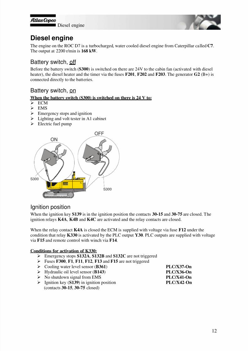
Diesel engineThe engine on the ROC D7 is a turbocharged, water cooled diesel engine from Caterpillar called C7 .The output at 2200 r/min is 168 kW .
Battery switch, offBefore the battery switch ( S300 ) is switched on there are 24V to the cabin fan (activated with dieselheater), the diesel heater and the timer via the fuses F201 , F202 and F203 . The generator G2 (B+) isconnected directly to the batteries.
Battery switch, onWhen the battery switch (S300) is switched on there is 24 V to:
ECM EMS Emergency stops and ignition Lighting and volt tester in A1 cabinet Electric fuel pump
S300
S300
ONOFF
Ignition positionWhen the ignition key S139 is in the ignition position the contacts 30-15 and 30-75 are closed. Theignition relays K4A , K4B and K4C are activated and the relay contacts are closed.
When the relay contact K4A is closed the ECM is supplied with voltage via fuse F12 under thecondition that relay K330 is activated by the PLC output Y30 . PLC outputs are supplied with voltage via F15 and remote control with winch via F14 .
Conditions for activation of K330: Emergency stops S132A , S132B and S132C are not triggered Fuses F300 , F1 , F11 , F12 , F13 and F15 are not triggered Cooling water level sensor ( B361 ) PLC/X37-On Hydraulic oil level sensor ( B143 ) PLC/X36-On No shutdown signal from EMS PLC/X41-On Ignition key ( S139 ) in ignition position PLC / X42 -On
(contacts 30-15 , 30-75 closed)

7/25/2019 Descripcion Roc Nva Cabina Roc d5-d7
http://slidepdf.com/reader/full/descripcion-roc-nva-cabina-roc-d5-d7 14/78
Diesel engine
13
When the relay contacts K4B and K4C are closed the control panel in the cab is supplied with voltage,which regulates working lights and seat heating amongst other things.
During the ignition phase, the fault indications lamps on the diesel panel are flashing for 2 secondswhile the ECM conducts a self test, PLC outputs Y27, Y31, Y32, Y33 are also activated for lamp test.During this time the engine will not be able to start.
Start positionConditions for activation of starter motor:
Emergency stops S132A , S132B and S132C are not triggered Fuses F300 , F1 , F11 , F12 , F13 and F15 are not triggered S130 in tramming mode PLC/X24-Off Compressor switch ( S180 ) off H180 off Ignition key ( S139 ) in start position PLC / X34 -On
(contacts 30-15 , 30-50 closed)Note : PLC / X34 can only be activated when the compressor switch ( S180 ) is not activated, otherwisethe S180 contact will block the input signal to PLC/X34 .
If the conditions above are fulfilled, PLC output Y24 is on which activates K5B which in turn pre-controls relay K5A . When relay K5A closes, the starter motor ( M1 ) is activated.
PLC / Y24 -On → K5B relay → K5A relay → M1 is activated, i.e. engine is cranking.
The ECM is normally powered through PLC ouput operated by K330 . When turing the starter motorthere will be voltage drop in the system which can temporarily cause the PLC to shut down. To ensurepower supply to the ECM , which is necessary for starting the engine, one of the contacts of K5B isbridging the contatct of K330 . This allows the ECM to be powered from the main electrical system.
During the starting phase, the ECM blocks any signal from the oil pressure switch for 15 seconds.This is to prevent the engine from stopping if the start key is released as soon as the engine has started,but the engine has not yet built up the correct oil pressure.
Control instrumentationFollowing instruments monitors the diesel engine.
Diesel fuel gauge P352The fuel transducer B352 in the fuel tank sends a signal to the fuel gauge, proportional to the fuellevel. There is an adjusting screw on the backside of P352 for calibrating the true fuel level. Thelamp comes on when there are 75 litres remaining.
Engine Monitoring System P354VDO, tachometer with display . The EMS monitors and processes engine operating parametersand diagnostic information. The unit has a digital LCD display which can read out the differentengine parameters monitored and display fault symbols when faults occur. Press button (S354) onthe VDO instrument in order to scroll between the menus on the display. Depress button (S354)for 5 seconds to zero or acknowledge, and doubleclick in order to access Caterpillar's fault codesfor an alarm situation.
Button for display S354
Contrast adjustment knob R354

7/25/2019 Descripcion Roc Nva Cabina Roc d5-d7
http://slidepdf.com/reader/full/descripcion-roc-nva-cabina-roc-d5-d7 15/78
Diesel engine
14
Fault indicatorsThe rig has monitoring functions to check that all data is relevant and correct. In the event of certainfaults, the diesel engine is turned off automatically. Other faults are merely indicated, which requiresthe engine to be switched off and the fault rectified.
Indicator lamp H207Indicator lamp for clogged air filter for dieselengine and compressor. The lamp comes onwhen the filters are clogged.
Indicator lamp H211Alarm lamp for diesel engine monitoring.The lamp comes on in the event of a fault codefrom the diesel engine.
Indicator lamp H212Alarm lamp for diesel engine monitoring.The lamp comes on in the event of a falut codefrom the diesel engine that switchese off theengine.
Indicator lamp H213Alarm lamp for rig monitoring. The lampcomes on in the event of an alarm.
Indicator lamp H214Alarm lamp for rig monitoring. The lamp comes on in the event of an alarm that switches off theengine.
Indicator lamp H203Signal lamp, low hydraulic oil level. The lamp comes on when the oil level is too low and theengine is switched off.
Indicator lamp H215Indicator lamp for engine coolant level. The lamp comes on when the coolant level is too low.
Indicator lamp H381Indicator lamp for ECL collection. The lamp indicates inadequate pressure in the return line. Itcomes on when drilling starts until the correct pressure is achieved.
Indicator lamp H382Indicator lamp for ECL collection. The lamp indicates excessive pressure in the return line. Thecan be due to the return tank is being full.
Note : All faults should be checked thoroughly and rectified.
H207
H382H381
H215H203
P352H180
H214H212
H213
H211
R354
S354
P354

7/25/2019 Descripcion Roc Nva Cabina Roc d5-d7
http://slidepdf.com/reader/full/descripcion-roc-nva-cabina-roc-d5-d7 16/78
Diesel engine
15
Engine speedThe engine speed can be de- or increased by flicking switch S189 up-or downwards. By flicking the switch different times, this puts theN189 connections (Din0-2) in different set of combinations, hence
providing the different engine revolutions, and this is controlled bythe PLC output Y35-Y37 respectively.
PLC can support 8 engine revolutions, and it can store 3 separateengine speeds, one for tramming, one for rod handling and one fordrilling. The PLC remembers the engine speeds when the rig is beingshut. The speeds can all be set individually within the range specifiedbelow.
Condition for revolution between 1200-2200 tramming positionSwitch S130 NOT in drilling position
Condition for revolution between 1500-2200Switch S130 in drilling position and reduced flashing air NOTactivated (Y116/OFF)
Condition for revolution between 1800-2200Switch S130 in drilling position and reduced flushing air activated (Y116/ON)
The engine starts on idling speed 1200 rpm, flicking the switch once upwards should increase thespeed to 1500 rpm, one more flick increases the speed to 1700 rpm, then the engine speed increaseswith 100 rpm per flick upwards until it reaches the maximum speed of 2200 rpm. It is also possible tohold the switch for several seconds in order to reach the maximum speed. To decrease the enginespeed from the idling speed, flick the switch once downwards stake down the speed step by step justlike upwards. When changing from tramming position to drilling, the engine speed automaticallyincreases to engine speed set for drilling and vice versa.
Engine revolution combinations from PLC Y35-Y37PLC Y35
/N189 Din2PLC Y36
/N189 Din1PLC Y37
/N189 Din0Engine speed RPM
Low Low Low 1200 RPMLow Low High 1500 RPMLow High High 1700 RPMLow High Low 1800 RPMHigh High Low 1900 RPM
High High High 2000 RPMHigh Low High 2100 RPMHigh Low Low 2200 RPM
a
b
c
ab c
d

7/25/2019 Descripcion Roc Nva Cabina Roc d5-d7
http://slidepdf.com/reader/full/descripcion-roc-nva-cabina-roc-d5-d7 17/78
Compressor
16
Compressor
GeneralThe built-in compressor is a single-stage compressor. Its normal working pressure is 10.5 bar with theCaterpillar diesel engine.
Compressor unitThe compressor unit comprises two rotors: a drive rotor and a slide rotor mounted on rollers and ballbearings. The drive rotor is driven by the diesel engine and transfers power to the slide rotor. Therotors are lubricated with oil that is injected and mixed with the air. This increases efficiency since theoil forms a seal between the rotor blade and the housing. The compressor unit is an Atlas Copco typeG106 screw compressor. The gear ration is 1.55.
Air flow
The intake air is drawn through the air filter and an over centre valve to the compressor unit. The overcentre valve also prevents oil returning into the system. The air is mixed with injected oil and goesdirectly from the compressor to the air receiver. In the air receiver, the majority of the oil is separatedfrom the air/oil mixture using an oil separator. This oil is removed by a separator unit. The flow ofcompressed air passes through a pressure valve to the drill rigs air system. The pressure valve preventsthe pressure in the air receiver dropping below the lowest working pressure for the compressor(approx. 2.8 bar), even when the air outlet valves are open, to ensure the correct function of the oilsystem.
Air Atmospheric Pressure
Air Regulating Pressure
Air Working Pressure
Air/Oil Mixture
Oil

7/25/2019 Descripcion Roc Nva Cabina Roc d5-d7
http://slidepdf.com/reader/full/descripcion-roc-nva-cabina-roc-d5-d7 18/78
Compressor
17
Cooling and oil systemsOil is used for lubrication, sealing and cooling. There is no oil pump with pressure provided by the airpressure. The lower part of the air receiver acts as an oil tank. The air pressure means that the oil istransported from the air receiver through the oil cooler and oil filter to the compressor unit. The
compressor unit has an oil platform at the bottom of the sleeve. The oil for rotor lubrication, coolingand sealing is injected through a hole in this oil platform. The bearings are lubricated by oil injectedinto the bearing housing. The air/oil mixture leaves the compressor unit and returns to the air receiver,where the oil is separated from the air. The oil that is collected at the bottom of the oil separatorreturns to the oil system through a cleaning line that has a flow limiter.Note: A thermostat valve bypasses the oil cooler when the oil is below 70°C .
Air Atmospheric Pressure
Air Regulating Pressure
Air Working Pressure
Air/Oil Mixture
Oil
Regulator systemThe compressor control system comprises a regulator valve. This valve controls the air volume
supplied by the compressor for air consumption whilst also keeping the working pressure within acertain range. The control system also includes a load valve that is activated by a switch on the dieselcontrol panel. The load valve allows the diesel engine to warm up before engaging the compressor.
Instrument and fault indicationThe pressure of the compressed air delivered from the compressor can be read from the pressuregauge. The compressor also has a temperature indicator switch ( B366 ), which automatically providesindication and displays in plain text on the display that the temperature has risen. The system switchesoff the diesel engine if the compressor temperature exceeds +120°C .
7/25/2019 Descripcion Roc Nva Cabina Roc d5-d7
http://slidepdf.com/reader/full/descripcion-roc-nva-cabina-roc-d5-d7 19/78
Pumps and pilot pressure
18
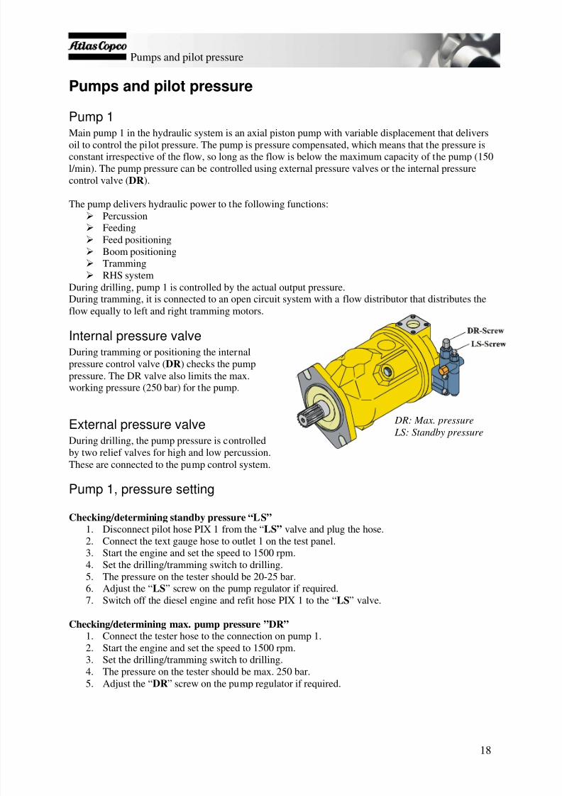
Pumps and pilot pressure
Pump 1Main pump 1 in the hydraulic system is an axial piston pump with variable displacement that deliversoil to control the pilot pressure. The pump is pressure compensated, which means that the pressure isconstant irrespective of the flow, so long as the flow is below the maximum capacity of the pump (150l/min). The pump pressure can be controlled using external pressure valves or the internal pressurecontrol valve ( DR ).
The pump delivers hydraulic power to the following functions: Percussion Feeding Feed positioning Boom positioning Tramming
RHS systemDuring drilling, pump 1 is controlled by the actual output pressure.During tramming, it is connected to an open circuit system with a flow distributor that distributes theflow equally to left and right tramming motors.
Internal pressure valveDuring tramming or positioning the internalpressure control valve ( DR ) checks the pumppressure. The DR valve also limits the max.working pressure (250 bar) for the pump.
External pressure valveDuring drilling, the pump pressure is controlledby two relief valves for high and low percussion.These are connected to the pump control system.
Pump 1, pressure setting
Checking/determining standby pressure “LS”1. Disconnect pilot hose PIX 1 from the “ LS” valve and plug the hose.2. Connect the text gauge hose to outlet 1 on the test panel.
3. Start the engine and set the speed to 1500 rpm.4. Set the drilling/tramming switch to drilling.5. The pressure on the tester should be 20-25 bar.6. Adjust the “ LS ” screw on the pump regulator if required.7. Switch off the diesel engine and refit hose PIX 1 to the “ LS ” valve.
Checking/determining max. pump pressure ”DR”1. Connect the tester hose to the connection on pump 1.2. Start the engine and set the speed to 1500 rpm.3. Set the drilling/tramming switch to drilling.4. The pressure on the tester should be max. 250 bar.5. Adjust the “ DR ” screw on the pump regulator if required.
DR: Max. pressure LS: Standby pressure

7/25/2019 Descripcion Roc Nva Cabina Roc d5-d7
http://slidepdf.com/reader/full/descripcion-roc-nva-cabina-roc-d5-d7 20/78
Pumps and pilot pressure
19
Pump 2Pump 2 delivers oil to the rock drill’s rotation motor. The maximum pump pressure for pump 2 is setvia the relief valve in the drill rotation circuit.
Pump 3 and 4Pumps 3 and 4 are fitted as a double pump on the diesel engine’s power take off.
Pump 3 delivers oil to the dust collector’s fan motor during drilling, or to the positioning/winchcircuit during tramming.During drilling, the pressure of pump 3 can be set on a relief valve in the DCT valve block.During tramming, the pressure of pump 3 is set constant at 210 bar.Pump 3 is unloaded at engine start-up.
Pump 4 drives the cooler motor for cooling the hydraulic oil, compressor oil as well as engine’sintake air and cooling water. It also delivers oil to the track oscillation lock mechanism. Pump 4 isa gear pump and is driven by the power take off on the side of the diesel engine. The pressure ofpump 4 cannot be adjusted but is controlled by the relief valve for the cooling fan. This is set to160 bar for D5 and 220 bar for D7. This pump is permanently active.
Pilot pressureThe oil that controls the pilot pressure comes from pump 1 and pump 3. The oil is led to the maindrilling block/winch block from respective pump through a pressure reducing valve (set to 35 bar),through a strainer and out to the pilot circuit.
The oil in the main drilling block is led through solenoid valve Y121 , which guides the pilot pressureeither to the drilling or tramming circuit. To protect the pilot system against pressure surges, there is apressure limiting valve set to 50 bar. The oil is then led to the solenoid valve Y169 , which shuts off thepilot pressure supply to tramming and impact functions in the event of an emergency stop situation orwhen the automatic drill-stop function is used.
P1 → 35 bar (pilot) → Drilling function, tramming function, tramming speed controlP3 → 35 bar (pilot) → Winch function, positioning function

7/25/2019 Descripcion Roc Nva Cabina Roc d5-d7
http://slidepdf.com/reader/full/descripcion-roc-nva-cabina-roc-d5-d7 21/78
Tramming
20
Tramming
ConditionsThe tramming circuit includes functions for activating hydraulic functions that maintain thetramming circuit and control the hydraulic power to the tramming motors.
Condition for Tramming:- Drilling/Tramming switch S130 must be in a tramming position.
The pilot pressure is led through solenoid valve Y169 , the function of which is to cut the pilot pressureflow to tramming and impact functions in an emergency. When solenoid valve Y169 is activated, theoil is led to valve Y121 which then leads the pilot pressure to either the drilling circuit or trammingcircuit. Y121 is controlled by switch S130 (see Fig. 1).
High and low speed can be selected. If low speed is selected, the pilot pressure is led through solenoid
valve Y121 and then to the directional valve in the main drilling block (see Fig. 2). If high speed isactivated, the pilot pressure is led through valve Y122 and on to the valve block for the trammingmotors (see Fig. 4).
Y122 Y121Y169 Fig. 1: See full diagram for other parts
No.: 9840 0423 56 page 3(16)
The pilot pressure then activates the directional valve (see Fig. 2) in the main drilling block andsupplies the tramming block via the flow regulator with oil (see Fig. 3).

7/25/2019 Descripcion Roc Nva Cabina Roc d5-d7
http://slidepdf.com/reader/full/descripcion-roc-nva-cabina-roc-d5-d7 22/78
Tramming
21
Y120A RotationPercussion
Rapid feedr ee
Directional valve
Fig. 2: See full diagram for other parts No.: 9840 0423 56 page 2(16)
Tramming direction and speed is controlled by means of pilot pressure controlling the proportionaldirectional valves. There directional vavles are controlled by the tramming levers in the cabin(see Fig. 3).
Tramming direction and speed can also be controlled using the tramming controls on the remotecontrol box (see chapter “Option”). These controls send a signal to the control valves ( Y206, Y207 )for tramming forward or backward. The pilot pressure alters the position of the directional valvesproportionally. When the remote control box is activated, the tramming controls in the cab areblocked.
Flow regulatorPump 1
P i l o t p r e s s u r e
Y206A
Y206B
Y207A
Y207B
Fig. 3: See full diagram for other parts
No.: 9840 0423 56 page 4(16)

7/25/2019 Descripcion Roc Nva Cabina Roc d5-d7
http://slidepdf.com/reader/full/descripcion-roc-nva-cabina-roc-d5-d7 23/78
Tramming
22
The valve block integrated in the tramming motors comprises a reversing valve, pilot brake valve anda pilot sequence valve for releasing the tramming brake once the motor is pressurized. The pressureregulator protects the brake cylinder from high pressure. For high-speed tramming, the valves areactivated by the pilot pressure as in the figure below.
Reversing valve
Brake valve
Reversing valve
Sequence valve
Pressure regulator
Brake cylinder
Pilot pressure, high speed
Fig. 4: See full diagram for other parts No.: 9840 0423 56 page 4(16)
Tramming warningWhen tramming backwards the pressure switches B174 and B175 gives a signal to the reversingwarning signal ( H185 , H186 ) / flash.
The warning signal can also be activated manually by using switch S186 .
Hydraulic jack
The rear jack is controlled by switch S209 , which energizes solenoid valves Y410A/B . Unlike theother rigs, it is possible to tram with the rear jack while it is out.
7/25/2019 Descripcion Roc Nva Cabina Roc d5-d7
http://slidepdf.com/reader/full/descripcion-roc-nva-cabina-roc-d5-d7 24/78
Positioning
23
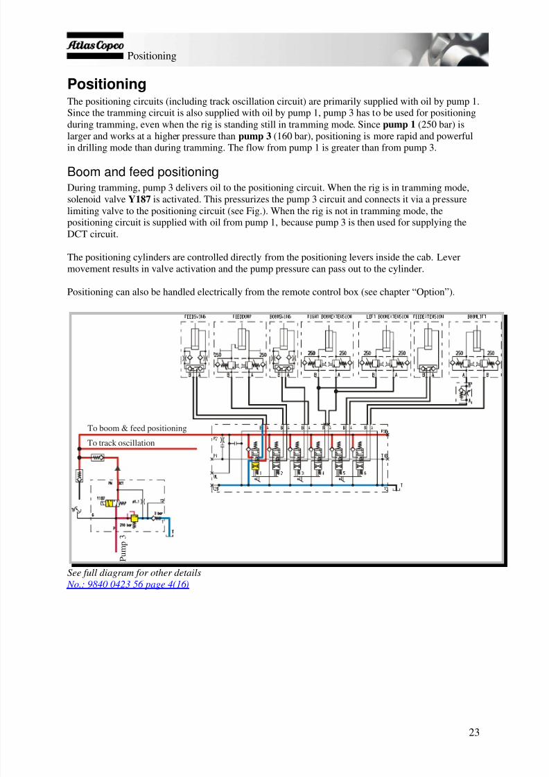
PositioningThe positioning circuits (including track oscillation circuit) are primarily supplied with oil by pump 1.Since the tramming circuit is also supplied with oil by pump 1, pump 3 has to be used for positioningduring tramming, even when the rig is standing still in tramming mode. Since pump 1 (250 bar) is
larger and works at a higher pressure than pump 3 (160 bar), positioning is more rapid and powerfulin drilling mode than during tramming. The flow from pump 1 is greater than from pump 3.
Boom and feed positioningDuring tramming, pump 3 delivers oil to the positioning circuit. When the rig is in tramming mode,solenoid valve Y187 is activated. This pressurizes the pump 3 circuit and connects it via a pressurelimiting valve to the positioning circuit (see Fig.). When the rig is not in tramming mode, thepositioning circuit is supplied with oil from pump 1, because pump 3 is then used for supplying theDCT circuit.
The positioning cylinders are controlled directly from the positioning levers inside the cab. Lever
movement results in valve activation and the pump pressure can pass out to the cylinder.
Positioning can also be handled electrically from the remote control box (see chapter “Option”).
P u m p
3
To boom & feed positioning
To track oscillation
See full diagram for other details
No.: 9840 0423 56 page 4(16)
7/25/2019 Descripcion Roc Nva Cabina Roc d5-d7
http://slidepdf.com/reader/full/descripcion-roc-nva-cabina-roc-d5-d7 25/78
Positioning
24
Figure: Open positionSee full diagram for other details
No.: 9840 0423 56 page 4(16)
Figure: Closed position
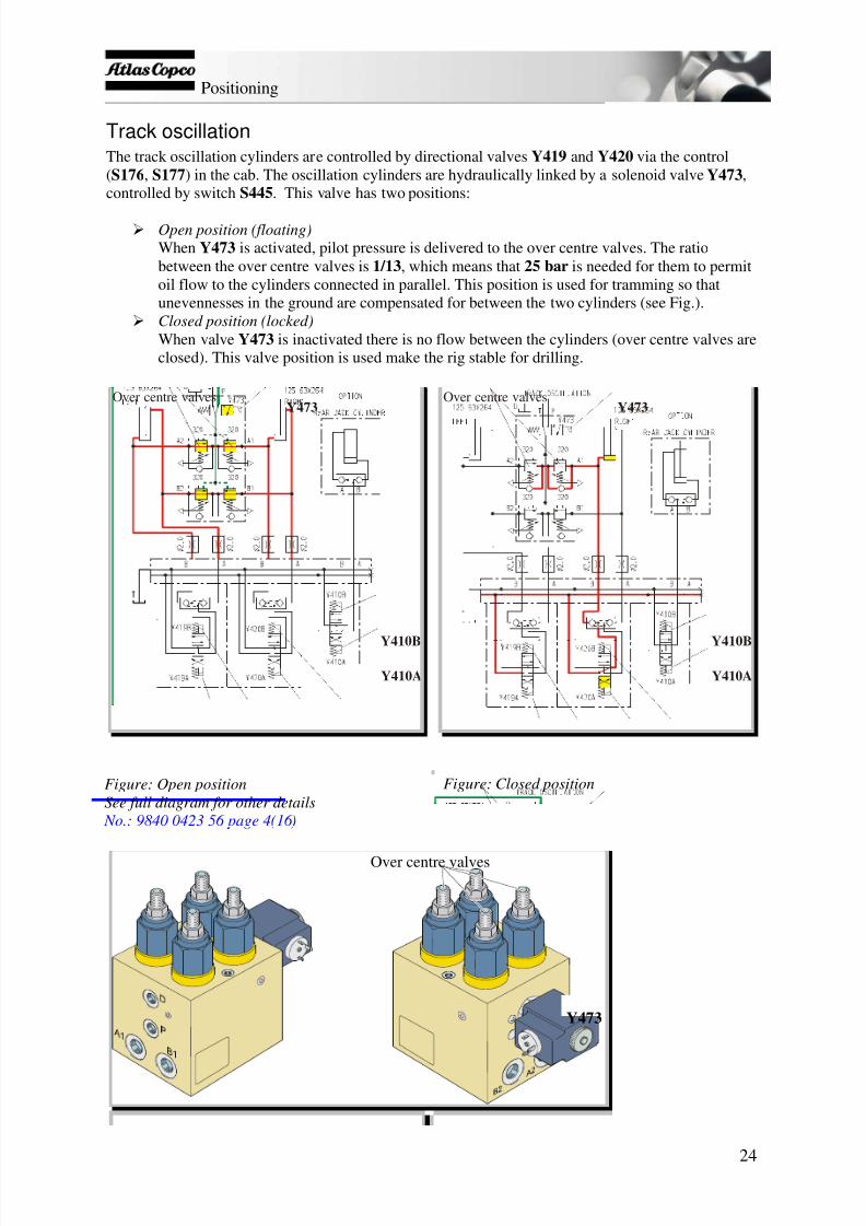
Track oscillationThe track oscillation cylinders are controlled by directional valves Y419 and Y420 via the control(S176 , S177 ) in the cab. The oscillation cylinders are hydraulically linked by a solenoid valve Y473 ,controlled by switch S445 . This valve has two positions:
Open position (floating)When Y473 is activated, pilot pressure is delivered to the over centre valves. The ratiobetween the over centre valves is 1/13 , which means that 25 bar is needed for them to permitoil flow to the cylinders connected in parallel. This position is used for tramming so thatunevennesses in the ground are compensated for between the two cylinders (see Fig.).
Closed position (locked)When valve Y473 is inactivated there is no flow between the cylinders (over centre valves areclosed). This valve position is used make the rig stable for drilling.
Y419BY419A Y420A Y420B
Y410A
Y410B
Y473Over centre valves
Y419BY419A Y420A Y420B
Y410A
Y410B
Y473Over centre valves
Y473
Over centre valves

7/25/2019 Descripcion Roc Nva Cabina Roc d5-d7
http://slidepdf.com/reader/full/descripcion-roc-nva-cabina-roc-d5-d7 26/78
Oil pre-heating
25
Oil pre-heatingPump 2 is used for pre-heating the hydraulic oil. Normal operating temperature of the hydraulic oil is40°C. Before operating the drill rig the oil should be pre-heated to minimum operating temperature,20°C.
When switch S130 is in the pre-heating position, solenoid valve Y120A in the main drill block isactivated. The oil must pass through a 2 mm restriction and create a pressure by the pressure limitingvalve (170 bar). The oil heats up. (See red marker in figure.)
Pressure limiting valveShunt valve Pressure valves
Directional valve
See full diagram for other details No.: 9840 0423 56 page 2(16)

7/25/2019 Descripcion Roc Nva Cabina Roc d5-d7
http://slidepdf.com/reader/full/descripcion-roc-nva-cabina-roc-d5-d7 27/78
Drilling
26
DrillingConditions for drill lever:Input → PLC in → PLC ut → OutputS130 drilling PLC / X24 -On
S452 drilling mode PLC / X50 -Off PLC / Y40 -Off K178 deactivatedPLC/Y41-On Y179A, Y179B activatedPLC/Y42-On H452 activated
OrS452 in rapid feed/ PLC/X50-On PLC/Y40-On K178 activated → Y178A-D activatedthreading mode PLC/Y41-Off Y179A, Y179B deactivated
PLC/Y42-Off H452 deactivated
Led greenH452
75
6
8
B
C I
H
GAD
F
Drill rotationMagneticholding
Drill feedMagnetic holding
E
Impact lowS446A
Rapid/ drill feedS452
Magnet off S453
Led yellowH446
Impact highS446B
Drill mode:E: neutralB: rotation anti-clockwiseB+A: rotation anti-clockwise and feed forward(magnet function )B+C: rotation anti-clockwise ( magnet function )and feed backward.D: feed forward ( magnet function )
F: feed backwardH: rotation clockwiseH+G: rotation clockwise and feed forwardH+I: rotation clockwise and feed backward
Diode H452 is lit in this mode.
Rapid feed / threading mode:E: neutralB: threadingB+A: rotation anti-clockwise and rapid feedforwardB+C : rotation anti-clockwise and rapid feedbackwardD: rapid feed forward
F: rapid feed backwardH: unthreadingH+G : rotation clockwise and feed forwardH+I: rotation clockwise and feed backward
There is no diode indication in this mode.
Magnetic holding on rotation during drilling or/and feeding forwards can only be achieved when thecontrol lever is being pulled to the end position, and when S452 is not activated (Led H452 = ON).Pulling the lever only half way and then release would result in lever springed back to the neutralposition, which also marks the end of the movement.

7/25/2019 Descripcion Roc Nva Cabina Roc d5-d7
http://slidepdf.com/reader/full/descripcion-roc-nva-cabina-roc-d5-d7 28/78
Drilling
27
Air flushingConditions for air flushing:Input → PLC in → PLC ut → OutputS130 drilling PLC/X24-On
S180 compressor activated Y6A activated B118 arm in carousel PLC/X3-OnS100 reduced air flushing PLC/X25-On OrS100 full air flushing PLC/X26-OnS446 activated* PLC/X27-On PLC/Y23 or Y116 activated or
PLC/Y22, Y23-On Y115 , Y116 activated
*When S446 is activated for shorter than 0.5 seconds, only air flushing is activated. When S446 isactivated for longer than 0.5 seconds air flushing and percussion are activated.Note : The air flushing mode (Full/Reduced or off) that is obtained with activation of S446 (percussion/air flushing) depends on the position of S100 .
Activating switch S446 for again for shorter than 0.5 seconds would deactivate flushing.
B142 B115 Y116
See full diagram for other details
No.: 9840 0423 22 page 2(3)
Air flushing modes Air flushing is controlled by an electrical switch, S100 ; there are three air flushing modes: reduced,full and off. These activate the solenoid valves Y116 and Y115 . When reduced air flushing is selectedY115 is switched off and the air flows via Y116 and can then be regulated with a control valve (seefigure).
Flow switchWhen full flushing ( Y115 and Y116 activated) is selected the flow switch (B142 ) functions asprotection against clogging the drill bit when drilling through clay or softer layers of rock. Thepressure increases when the bit clogs and the difference over a restrictor decreases. The contact toB142 will close and drill feed backward is activated via valve Y109 in the drill feed hydraulic circuit.This is controlled via the PLC.

7/25/2019 Descripcion Roc Nva Cabina Roc d5-d7
http://slidepdf.com/reader/full/descripcion-roc-nva-cabina-roc-d5-d7 29/78
Drilling
28
RotationCondition for rotation:- Drilling/Tramming switch S130 must be in drilling position → PLC/X24-On - Switch S452 must be in drilling mode → PLC/X50-Off
The hydraulic oil for drill rotation is supplied from pump 2. The drill rotation circuit includesfunctions for rotation direction and controlling the rotation speed. The anti-jamming system is partlyincluded in the rotation circuit. That circuit is described later.
Activating the drill rotation functionWhen the Drilling/Tramming switch S130 is in drilling position, the solenoid valve Y121 is notactivated. This allows the pilot pressure to connect to hydraulic components in the drilling system likethe rotation lever.
Rotation directionThe rotation sector, position (B) and (H), controls the maindirectional valve for clockwise or anti-clockwise rotation via therotation flow control and the LOGIC-2 block.
Main drill blockThe pilot operated directional valve (see Fig.), directs both thehydraulic power to the rotation motor of the rock drill and actsas a constant flow regulator together with the shunt valve. Thetwo-pressure relief valves (see Fig.) limit the maximum pressureto the rotation motor.
Y120A
Pressure limiting valveShunt valve Pressure valves
Directional valve
See full diagram for other details No.: 9840 0423 56 page 2(16)
Rotation pressuresThe rotation pressure is generated by pump 2. Depending on the direction of rotation, a pressure reliefvalve is activated to limit the maximum pressure for anti-clockwise and clockwise rotationrespectively. The maximum pressure for rotation anti-clockwise is limited to 125 bar, and themaximum pressure of rotation clockwise is limited to 160 bar.
75
6
8
B
C I
H
GAD
F
E

7/25/2019 Descripcion Roc Nva Cabina Roc d5-d7
http://slidepdf.com/reader/full/descripcion-roc-nva-cabina-roc-d5-d7 30/78
Drilling
29
Rotation speed- Anti-clockwise rotation (drilling)The pilot pressure passes a flow regulator (see Fig.) which regulates the rotation speed. The settingof the flow regulator controls how much the directional valve will open. The flow to the rock drillrotation motor is proportional to the opening of the directional valve.The forward rotation pilot pressure also activates the DPC-I system (For further information, referto section “DPC-I system” under chapter “Damper & DPC-I system”).- Clockwise rotationThe drill lever controls the rotation speed. The main directional valve opens in correspondence tothe lever angel. The flow regulator is not connected.
The adjustment knob for flow regulator can be found in chapter “Adjustment/calibration”.
Pilot-p
R+
Controls the pilot pressure See full diagram for other details
No.: 9840 0423 56 page 3(16)
160bar
125bar
250bar
160barY120
Drill feed-Rpd feed-
Impact-Rotation-
Pressure, pump 2
Pressure, pump 1
To tank
160bar
11bar
Figure: Drilling block

7/25/2019 Descripcion Roc Nva Cabina Roc d5-d7
http://slidepdf.com/reader/full/descripcion-roc-nva-cabina-roc-d5-d7 31/78
Drilling
30
Drill feedCondition for drill feed:- Drilling/Tramming switch S130 must be in drilling position → PLC/X24-On - Switch S452 must be in drilling mode → PLC/X50-Off
The feed circuit is supplied with oil by pump 1 and includes functions for feeding the rock drill cradleup and down the feed beam and controlling the feed pressure during collaring and drilling (high andlow pressure). The anti-jamming circuit is described seperately.
Activating the drill feed functionWhen the Drilling/Tramming switch S130 is in drilling position, the solenoid valve Y121 is notactivated. This allows the pilot pressure to connect to hydraulic components in the drilling system likethe feed lever.
Drill feed direction, up-/downwards The drill feed sector, position (D) and (F), controls the maindirectional valve for drill feed via the LOGIC-2 block.
NOTE: The anti-jamming system can automatically change thefeed direction. See chapter “Anti-jamming”.
Main drill block The pilot operatered directional valve (see Fig.) in the main drillblock, directs the hydraulic power to the feed cylinder. The pilotoperated pressure reducing valve (see Fig.) regulates the feedworking pressure.
Pressure relief valvesDirectional valvePressure reducing valve
See full diagram for other details No.: 9840 0423 56 page 2(16)
75
6
8
B
C I
H
GAD
F
E

7/25/2019 Descripcion Roc Nva Cabina Roc d5-d7
http://slidepdf.com/reader/full/descripcion-roc-nva-cabina-roc-d5-d7 32/78
Drilling
31
Feed pressures The feed pressure can be read on pressure gauge in the cab.Two pressure relief valves (100 and 230 bar) limit the max. pressure to the feed cylinder, downwardsand upwards respectively.When feedling downwards (drilling), the pressure reducing valve in the main drill block is controlledby either pressure relief valve for low or high feed pressure respectively (see Fig.). The impact controlswitch S446 position determines which valve is controlling the pressure as follow:
o Low feed pressure (collaring) When switch S130 is in Drilling position, solenoid valve Y101B is activated. This activatesQDS valve E , which allows the low feed pressure relief valve to control the pressure reducingvalve in the main drill block. This is also the case when the impact control switch S446 is inlow impact position.
o High feed pressure (drilling) When the impact control switch S446 is in high impact position, Y101B is de-activated. Thismeans that QDS-E is de-activated and the high feed pressure relief valve controls the pressure
reducing valve in the main drill block.o Feeding upwardsThe QDS valve F is activated when feeding upwards. This prevents the two pressure reliefvalves for high and low feed pressure to control the feed pressure reducing valve in the maindrill block. In this case the feed pressure is limited by the pressure relief valve for feedbackwards (230 bar) in the rapid feed section of the main drill block.
Pressure relief valve, low feed pressure
Pressure relief valve, high feed pressure
See full diagram for other details No.: 9840 0423 56 page 2(16)

7/25/2019 Descripcion Roc Nva Cabina Roc d5-d7
http://slidepdf.com/reader/full/descripcion-roc-nva-cabina-roc-d5-d7 33/78
Drilling
32
PercussionConditions for low percussion with air flushing with function self-holding:Input → PLC in → PLC ut → OutputS130 drilling PLC/X24-On PLC/Y17-On Y101B activated
S180 compressor activated Y6A activated B118 arm in carousel PLC/X3-OnS100 air flushing PLC/X25 or X26-OnS452 drilling mode PLC/X50-Off PLC/Y41-On Y179A, Y179B activated
PLC/Y42-On H452 activatedS446A low percussion* PLC/X27-On PLC/Y20-On Y101A activated
PLC/Y43-On H446 blicking signalPLC/Y23 or/and Y22- Y116 or/and Y115 On activated
* S446A (low percussion) must be activated for longer than 0.5 seconds.
Conditions for high percussion with air flushing with function self-holding:Input → PLC in → PLC ut → OutputS130 drilling PLC/X24-On PLC/Y17-On Y101B activatedS180 compressor activated Y6A activated B118 arm in carousel PLC/X3-OnS100 air flushing PLC/X25 or X26-OnS452 drilling mode PLC/X50-Off PLC/Y41-On Y179A, Y179B activated
PLC/Y42-On H452 activatedS446A low percussion* PLC/X27-On PLC/Y20-On Y101A activated
⇓⇓⇓⇓ S446B high percussion* PLC/X30-On PLC/Y17-Off Y101B deactivated
PLC/Y20-On Y101A activated PLC/Y43-On H446 stable signalPLC/Y23 or/and Y22- Y116 or/and Y115 On activated
* S446A/B (high/low percussion) must be activated for longer than 0.5 seconds.
NOTE: Magnetic holding on rotation during drilling or/and feeding forwards can only be achievedwhen the control lever is being pulled to the end position. Pulling the lever only half way and thenrelease would result in lever springed back to the neutral position.
Conditions for percussion without air flushing (e.g. drilling in water): Note: Switch S446A/B must be held in at all time, since no self-holding is available here. Input → PLC in → PLC ut → OutputS130 drilling PLC/X24-On PLC/Y17-On Y101B activatedB118 arm in carousel PLC/X3-OnS100 air flushing off PLC/X25 and X26-OffS452 drilling mode PLC/X50-Off
PLC/Y17-On Y101B activated*S446 percussion activated(switch held in at all time)
PLC/X27 or X30-OnPLC/Y20-On Y101A activated
*Y101B is activated only during low percussion.
The percussion circuit includes functions for activating the rock drill’s percussion mechanisms andchecking the pressure for collaring and drilling (low and high pressure). The percussion pressure is
supplied by hydraulic pump 1. To protect the rock drill and drill steel, the DPC-I system can switch offor lower the percussion pressure if certain conditions are not fulfilled. The DPC-I system is describedseparately.

7/25/2019 Descripcion Roc Nva Cabina Roc d5-d7
http://slidepdf.com/reader/full/descripcion-roc-nva-cabina-roc-d5-d7 34/78
Drilling
33
Activating percussionThe directional valve in the main drilling block has two functions: to lead the oil to the rock drill’spercussion mechanism and to lead the oil to the tramming circuit. The directional valve is controlledby Y101A via the two QDS valves I and J (see figure below). If the damper pressure is lower than 35bar, valve QDS-I will close. If the pressure exceeds 120 bar, valve QDS-J will close. These QDSvalves are part of the DPC-I system and sense the rock drill’s damper pressure. If the damper pressuredoes not agree, the valves close to prevent the activation of the directional valve. When thepercussion pressure is activated, the pilot pressure is also led to QDS valve B which permits one of thepressure relief valves to take control of the pressure of pump 1.
To activate low percussion , press switch S446A (button to the left) for longer than 0.5seconds. Press the button one more time for shorter than 0.5 seconds would deactivatepercussion.
To activate high percussion , press switch S446B (button to the right) for longer than 0.5seconds under the condition that low percussion is activated first, or percussion would stop.Otherwise if starting directly on high percussion, the button for high percussion activationS446B must be held in at all time.
S446A/B controls the activation of solenoid valves Y115 , Y116 in the air system, but it is S100 thatcontrols the combination of Y115 and Y116. It’s recommended to keep S100 in full flushing airposition as soon as S446 is activated. S100 should be changed to reduced flushing air position onlywhen drilling through a weaker complex of the rock layer. S446A/B also control two solenoids valvesin the hydraulic system, Y101A , for activating percussion, Y101B , for activating low percussion.
Percussion pressureThe percussion pressure can be read from the pressure gauge in the cab. The pressure for low and highpercussion can also be adjusted there, see chapter “Adjustment/calibration”.
Low percussion pressure (pump 1): QDS valve B is activated once both solenoid valvesY101A and Y101B have been activated when switch S446 is in position for low percussion.
This connects control line “ DP ” for pump 1 to the pressure relief valve for high percussion,and if QDS valve A is not activated, to the pressure relief valve for low percussion.In the low percussion position, QDS valve C is active, which prevents QDS valve A beingactivated. Subsequently, the pressure relief valve for low percussion controls the pressure ofpump 1 .Note : In the low percussion position, QDS valve E is also activated to ensure low feed pressure.
High percussion pressure (pump 1): QDS valve B is still activated since solenoid valveY101A is ON when switch S446 is activated for high percussion. Since Y101B is OFF , QDS valve C is no longer activated, which means QDS valve A is controlled by the rock drill’sdamper pressure (DPC-I system). Normally, the rock drill’s damper pressure is greater than 50bar during drilling. This activates QDS valve A which prevents the relief valve for lowpercussion from controlling the pump pressure. The pump pressure is instead controlled by therelief valve for high percussion.
Impact hour counterThe PLC output Y20 gives a signal to the impact hour counter in the main electrical cabinet .
Y101AY101B
Figure: Percussion valves Figure: QDS valve

7/25/2019 Descripcion Roc Nva Cabina Roc d5-d7
http://slidepdf.com/reader/full/descripcion-roc-nva-cabina-roc-d5-d7 35/78
Drilling
34
Rapid feedConditions for the rapid feed functuion:- Drilling/Tramming switch S130 must be in drilling position → PLC/X24-On - Switch S452 must be in rapid feed/threading mode → PLC/X50-On
The rapid feed circuit includes functions for rapidly feeding upwards and downwards, and to stop thecradle in the correct positions for rod handling. The hydraulic power is supplied from Pump 1.
Activating the rapid feed functionWhen the Drilling/Tramming switch S130 is in drilling position, the solenoid valve Y121 is notactivated. This allows the pilot pressure to connect to hydraulic components in the drilling system likethe threading/rapid feed lever.
Rapid feed direction up-/downwards.The rapid feed sector, positions (D) and (F), controls the maindirectional valve for rapid feed via the LOGIC-2 valve block.The feed speed is proportional to the stroke of the lever.
Main drill blockThe pilot operated directional valve (see Fig.) in the main drillblock, directs the hydraulic power to the feed cylinder. The pilotoperated pressure reducing valve (see Fig.) regulates the feedworking pressure. The pressure relief valves (see Fig.) for rapidfeed (100 and 230 bar) limit the maximum pressure to the feedcylinder, downwards and upwards respectively.
Pressure relief valvesDirectional valvePressure reducing valve
See full diagram for other details No.: 9840 0423 56 page 2(16)
75
6
8
B
C I
H
GAD
F
E

7/25/2019 Descripcion Roc Nva Cabina Roc d5-d7
http://slidepdf.com/reader/full/descripcion-roc-nva-cabina-roc-d5-d7 36/78
Drilling
35
Rapid feed stopsThe rapid feed stop function is controlled by three inductive proximity switches connected to thePLC.B122 – Rapid feed stop downward just above the drill steel support.B127 – Rapid feed stop upwards, at a position above the RHS magazine, but before mechanical stop.B126 – Rapid feed stop when the coupling sleeve is inside the upper drill steel support (sensor lug A),and when the rod is in correct position to be inserted into the magazine (sensor lug B).
B127 B126
Indicator plate (A) (B)
B127 and B122 sensor plateB126 sensor plates
B122
?
ea f
d
b
c
a
b
c
S113
B122 , B126 and B127 are connected to PLC inputs X12 , X13 and X14 respectively. Provided theseinputs, the solenoid valves Y149 (upwards) or Y150 (downwards) in the LOGIC-2 valve block areactivated by PLC output Y3 or Y4 . Once activated, the rapid feed is stopped for 2 seconds.If the solenoid valves Y149 or Y150 are activated, the pilot connection between the rapid feed leverand the directional valve for the corresponding rapid feed direction will be blocked. Consequently therapid feed movement stops. Once activated, the rapid feed is stopped for 2 secondsThe input from B126 will only result in a rapid feed stop if switch S113 is in position (a) . This is toallow the rock-drill to be fast fed unstopped to the top when adding a drill steel.
7/25/2019 Descripcion Roc Nva Cabina Roc d5-d7
http://slidepdf.com/reader/full/descripcion-roc-nva-cabina-roc-d5-d7 37/78
Drilling
36
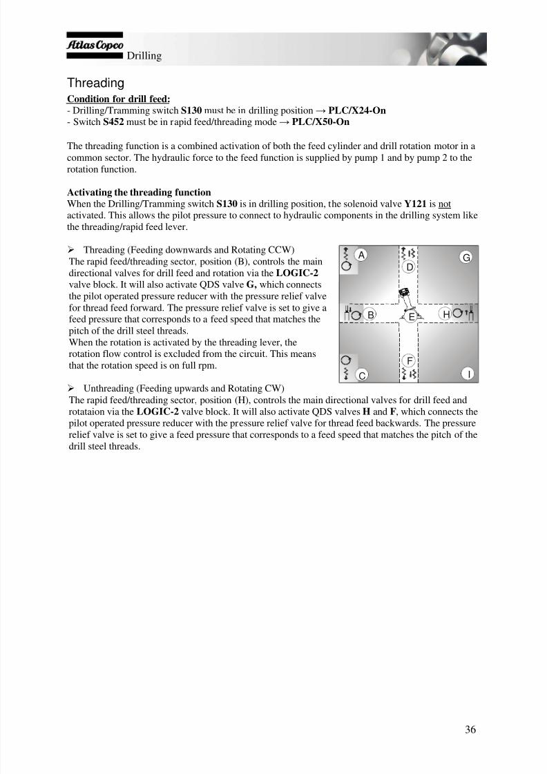
ThreadingCondition for drill feed:- Drilling/Tramming switch S130 must be in drilling position → PLC/X24-On - Switch S452 must be in rapid feed/threading mode → PLC/X50-On
The threading function is a combined activation of both the feed cylinder and drill rotation motor in acommon sector. The hydraulic force to the feed function is supplied by pump 1 and by pump 2 to therotation function.
Activating the threading functionWhen the Drilling/Tramming switch S130 is in drilling position, the solenoid valve Y121 is notactivated. This allows the pilot pressure to connect to hydraulic components in the drilling system likethe threading/rapid feed lever.
Threading (Feeding downwards and Rotating CCW)The rapid feed/threading sector, position (B), controls the maindirectional valves for drill feed and rotation via the LOGIC-2valve block. It will also activate QDS valve G, which connectsthe pilot operated pressure reducer with the pressure relief valvefor thread feed forward. The pressure relief valve is set to give afeed pressure that corresponds to a feed speed that matches thepitch of the drill steel threads. When the rotation is activated by the threading lever, therotation flow control is excluded from the circuit. This meansthat the rotation speed is on full rpm.
Unthreading (Feeding upwards and Rotating CW)The rapid feed/threading sector, position (H), controls the main directional valves for drill feed androtataion via the LOGIC-2 valve block. It will also activate QDS valves H and F, which connects thepilot operated pressure reducer with the pressure relief valve for thread feed backwards. The pressurerelief valve is set to give a feed pressure that corresponds to a feed speed that matches the pitch of thedrill steel threads.
75
6
8
B
C I
H
GA
D
F
E
7/25/2019 Descripcion Roc Nva Cabina Roc d5-d7
http://slidepdf.com/reader/full/descripcion-roc-nva-cabina-roc-d5-d7 38/78
Drilling
37
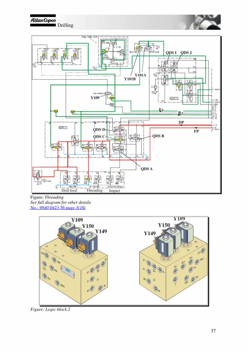
QDS I QDS J
Y101BY101A
QDS B
QDS A
QDS C
QDS D
Y109
F+R+
FP
Drill feed Threading Impact
DP
Figure: ThreadingSee full diagram for other details
No.: 9840 0423 56 page 3(16)
Y149
Y150Y149
Y150Y109
Figure: Logic block 2

7/25/2019 Descripcion Roc Nva Cabina Roc d5-d7
http://slidepdf.com/reader/full/descripcion-roc-nva-cabina-roc-d5-d7 39/78
Damper and DPC-I system
38
Damper and DPC-I systemThe rock drill's damper circuit is supplied with oil by pump 1 through a constant flow regulator. Theflow regulator is adjusted to a pressure of 35 bars at the damper hose connection on the rock drill.
The damper pressure during drilling indicates the actual feed force on the drill bit. The pressure can beread off from the pressure gauge in the cab on the rig. During drilling, the damper pressure controlscertain QDS valves, which in turn control the percussion pressure. This is described further underDPC-I system.
Adjusting damper pressureThe adjustment of damper pressure must take place with the damper piston in floating position. Toensure that the piston is in floating position the shank adapter must be pulled out as far as possible.Adjusting damper pressure should not be performed before the hydraulic oil has reached normalworking temperature, 40ºC (104ºF).
1. Connect a pressure gauge between the damper hoseconnection and the damper hose on the rock drill.2. Start the diesel engine and let it run at 1500 rpm.3. Make sure that the shank adapter is fully
withdrawn, i.e. the damper piston is in the floatingposition.
4. Set S130 in drilling position.5. Undo the lock screw (8b) on the knob and adjust
the damper pressure by turning the knob (8a):clockwise to lower the pressure and anticlockwiseto raise it.
6. Tighten the lock screw once the pressure is correct.
Note: Percussion should be stopped if the damper pressureexceeds 120 bars or drops below 35 bars.
DPC-I systemFunctionThe DPC-I system (Damper Pressure Controlled Impact) controls the percussion function by sensingthe damper pressure during drilling. Depending on the damper pressure, percussion may be permitted,stopped or switched between high and low percussion pressure. This is made possible by threesequence valves (QDS valves) in the r ig's hydraulic system.
QDS-I: Blocks the pilot pressure from percussion valve Y101A to the directional valve if the damperpressure is too low. In this case, the activation of percussion is prevented if the damper pressure isbelow 35 bars or percussion stops if the damper pressure drops below 35 bars during drilling incavities, a hose ruptures or a valve malfunctions.
QDS-J: Blocks the pilot pressure from percussion valve Y101A to the directional valve if the damperpressure exceeds 120 bars. This may occur if the feed pressure is abnormally high or if a mechanicalfault arises in the damper.
QDS-A: During normal drilling with high percussion pressure, QDS valve A is activated by thedamper pressure through QDS valve C and D. If the damper pressure drops below 50 bars, QDS-A isdeactivated. This means that the relief valve for low percussion controls the pump pressure instead of
the relief valve for high percussion pressure.
Figure: Damper pressure
Damper pressure
8a
8b

7/25/2019 Descripcion Roc Nva Cabina Roc d5-d7
http://slidepdf.com/reader/full/descripcion-roc-nva-cabina-roc-d5-d7 40/78
Damper and DPC-I system
39
Warning! Incorrect adjustment of the DPC-I system may damage the rock drill, rig and drill steels. Adjustment should only be made by a qualified technical engineer from Atlas Copco.
Setting the DPC-I systemThe DPCI system can be adjusted either in the workshop or on the drill site. Adjusting in theworkshop generally gives a more exact setting. On the other hand, adjusting during drilling can resultin a setting well adapted to the rock conditions and other system settings.In general, QDS-I should be set as high as possible without making it difficult to start impact.
Guidelines for setting QDS-valves. (Optimum setting might be higher). QDS-I QDS-J QDS-A35 bar 120 bar 50 bar
Setting during drilling
QDS-I, Setting during drilling:
1. Check that the damper pressure is adjusted according to “Adjusting the damper pressure”.2. Start drilling on low impact pressure and collaring feed pressure.3. Adjust the feed pressure slowly towards 0 while observing the damper pressure gauge.4. When the damper pressure drops below 35 bar as a result of the low feed pressure, impact should be
stopped automatically.5. If needed, adjust QDS-I CW to increase the setting or CCW to decrease it.6. Test the function by starting drilling on low impact pressure and collaring feed pressure. When the drill
cradle comes to a stop against the mechanical end stop, impact should shut of immediately. If not, thesetting of QDS-I should be increased.
NOTE! The setting of QDS-I should be the highest possible without making it difficult to start impact.This means that high collaring feed and damper pressures calls for a higher setting of QDS-I.
QDS-A, Setting during drilling:1. Check that the damper pressure is adjusted according to “Adjusting the damper pressure”.2. Start drilling. Make a good collaring, and then activate high impact pressure.3. Slowly decrease the feed pressure while observing the damper pressure gauge.4. The impact pressure should change from high to low when the damper pressure drops below 50 bar.5. If needed: Adjust QDS-A CCW to lower the setting and CW to increase it.
QDS-J, Setting during drilling:1. Check that the damper pressure is adjusted according to “Adjusting the damper pressure”.2. Start drilling on low impact pressure.
3. Increase the feed pressure towards maximum while observing the damper pressure gauge.4. When the damper pressure exceeds 120 bar, impact should be stopped automatically.5. If needed: Adjust QDS-J CCW to lower the setting and CW to increase it.
NOTE! During this adjustment there is an increased risk of getting stuck in the hole due to theincreased feed pressure.
NOTE! In soft rock conditions it can be difficult to force the damper pressure high enough. In thiscase the damper pressure regulator can be adjusted temporarily to 120 bar.

7/25/2019 Descripcion Roc Nva Cabina Roc d5-d7
http://slidepdf.com/reader/full/descripcion-roc-nva-cabina-roc-d5-d7 41/78
Damper and DPC-I system
40
Setting in workshop
QDS-I, Setting in workshop:1. Disconnect and plug the impact pressure hose on the rock-drill.
2. Start the diesel engine, increase the rpm to 1500 and turn switch S130 to Drilling position.3. Adjust the damper pressure to 35 bar, read on the damper pressure gauge in the cabin.4. Activate low impact pressure. Check the pressure on the impact pressure gauge in the cabin.5. Slowly adjust QDS-I in and out to find the activation point where the impact pressure disappears from the
gauge. CW increases the activation point and CCW lowers it. Finally, adjust slowly CCW until the impactpressure appears on the gauge again.
6. Verification: Increase and decrease the damper pressure a few times in order to verify that impact isstopped when the damper pressure is below 35 bar.
7. De-activate impact and turn off the diesel engine.8. Tighten the lock nut on QDS-I without changing the setting and reconnect the impact pressure hose on the
rock-drill.9. Adjust the damper pressure according to “Adjusting the damper pressure”. Verify through test drilling that
impact can not be activated unless the drill bit is pressed against the rock.
QDS-A, Setting in workshop:1. Disconnect and plug the impact pressure hose on the rock-drill.2. Start the diesel engine, increase the rpm to 1500 and turn switch S130 to Drilling position.3. Adjust the damper pressure to 50 bar, read on the damper pressure gauge in the cabin.4. Activate drill rotation.5. Activate high impact pressure. Check the pressure on the impact pressure gauge in the cabin.6. Slowly adjust QDS-A in and out to find the activation point where the impact pressure changes from high
to low. CW increases the activation point and CCW lowers it. Finally, adjust slowly CW until the impactchanges to low.
7. Verification: Increase and decrease the damper pressure a few times in order to verify that the impactpressure changes when the damper pressure passes 50 bar.
8. De-activate impact and turn off the diesel engine.9. Tighten the lock nut on QDS-A without changing the setting and reconnect the impact pressure hose on
the rock-drill.10. Adjust the damper pressure according to “Adjusting the damper pressure”. Verify through test drilling that
the impact pressure changes from high to low when the damper pressure drops below 50 bar if the feedpressure is lowered.
QDS-J, Setting in workshop:1. Disconnect and plug the impact pressure hose on the rock-drill.2. Start the diesel engine, increase the rpm to 1500 and turn switch S130 to Drilling position.3. Adjust the damper pressure to 120 bar, read on the damper pressure gauge in the cabin.4. Activate low impact pressure. Check the pressure on the impact pressure gauge in the cabin.5. Slowly adjust QDS-J in and out to find the activation point where the impact pressure disappears from the
gauge. CW increases the activation point and CCW lowers it. Finally, adjust slowly CW until the impactpressure disappears from the gauge again.
6. Verification: Increase and decrease the damper pressure a few times in order to verify that impact isstopped when the damper pressure exceeds 120 bar.
7. De-activate impact and turn off the diesel engine.8. Tighten the lock nut on QDS-J without changing the setting and reconnect the impact pressure hose on the
rock-drill.9. Adjust the damper pressure according to “Adjusting the damper pressure”. Verify through test drilling that
impact is stopped when the damper pressure exceeds 120 bar if the feed pressure is increased tomaximum.

7/25/2019 Descripcion Roc Nva Cabina Roc d5-d7
http://slidepdf.com/reader/full/descripcion-roc-nva-cabina-roc-d5-d7 42/78
Damper and DPC-I system
41
Related QDS valvesQDS-D: Activated by the pilot signal for drill rotation. In other words, the DPC-I only works whendrill rotation is active. When valve QDS -D is closed to damper pressure, it is open to the control line(DP ) for pump 1. This means that the DP pressure pilot controls QDS -A, which closes the pressurecontrol valve for low percussion. System pressure P1 is thus controlled by the pressure control valvefor high percussion.
QDS-C: Activated via Y101B (S130 in drilling position or low percussion being activated) or withreverse feed. This facilitates control of percussion pressure via the pressure control valve for lowpressure.

7/25/2019 Descripcion Roc Nva Cabina Roc d5-d7
http://slidepdf.com/reader/full/descripcion-roc-nva-cabina-roc-d5-d7 43/78
Damper and DPC-I system
42
Logic block 1
QDS-A
QDS-C
QDS-HQDS-G
QDS-QDS-E
QDS-DQDS-B
Logic block 2
Y149
Y150Y109
Y149Y150
Y109
Logic block 3
QDS-K
QDS-J
QDS-I
Y121
Y122
Y169

7/25/2019 Descripcion Roc Nva Cabina Roc d5-d7
http://slidepdf.com/reader/full/descripcion-roc-nva-cabina-roc-d5-d7 44/78
Protective protections
43
Protective protections
Anti-jammingThe anti-jamming protection is an automatic monitoring function that is always active during drilling.The anti-jamming function is activated by high rotation pressure or lack of air flushing flow duringdrilling.
Logic function of the leverSince the anti-jamming inverts the feed direction, pulling the drill lever for feeding backwards wouldresult in feed forward movement. To avoid this there is a pressure switch, B262 , connected to the pilotpressure line for feed backwards. B262 is connected to PLC input X33 , which, when active, inhibitsthe anti-jamming output Y2 .
FunctionWhen the anti-jamming protection is activated, the rock drill backs off until the jamming conditions
with regard to rotation pressure ( B134 ) and air flushing ( B142 ) cease to exist. The rock drill backs offuntil the rotation pressure returns to the permitted value (80 bars) or the air flushing is activated.
Conditions for anti-jamming protection with regard to high rotation pressure:Input → PLC in → PLC ut → OutputS130 drilling PLC/X24-OnB118 arm in carousel PLC/X3-OnS446 percussion activated PLC/X27 or X30-OnB134 activated PLC/X0-On PLC/Y2-On* Y109 activated*The minimum activation time for output Y2 is set by the PLC to 0.8 seconds.
If the rotation pressure exceeds 80 bars , sensor B134 is activated via QDS-K (see figure). The signal
is sent to the PLC (see preceding conditions) and the directional valve Y109 which controls thedirection of feed is activated.
Rotation PressureY109 B134 QDS-K
See full diagram for other details No.: 9840 0423 56 page 3(16)

7/25/2019 Descripcion Roc Nva Cabina Roc d5-d7
http://slidepdf.com/reader/full/descripcion-roc-nva-cabina-roc-d5-d7 45/78
Protective protections
44
Conditions for anti-jamming protection with regard to lack of air flushing:Input → PLC in → PLC ut → OutputS130 drilling PLC/X24-OnB118 arm in carousel PLC/X3-OnS100 full air flushing PLC/X26-OnS446 percussion activated PLC/X27 or X30-On PLC/Y22 and Y23-On Y115, Y116 activatedB142 activated PLC/X1-On PLC/Y2-On* Y109 activated*The minimum activation time for output Y2 is set by the PLC to 0.8 seconds.
To drill bit
B142
Y115
Y116Y109
See full diagrams for other details
No.: 9840 0423 56 page 3(16) No.: 9840 0423 22 page 2(3)
If there is no air flushing, sensor B142 is activated. A signal is sent to the PLC (see conditions above)and directional valve Y109 which controls feed direction is activated.
RPCFFunctionRPCF controls the feed pressure to maintain a constant rotation pressure (torque). If the rotationpressure exceeds an adjustable nominal value, the RPCF valve will be opened and the feed pressurereduced proportionally via the pressure control valve for low feed pressure. The feed pressure willalways lie between the values for low feed pressure and high feed pressure .
RPCF-valvePressure control valves
Fee pressure
See full diagrams for other details
No.: 9840 0423 56 page 3(16)
Note : The RPCF valve only controls the feed pressure when high percussion/feed pressure isactivated.

7/25/2019 Descripcion Roc Nva Cabina Roc d5-d7
http://slidepdf.com/reader/full/descripcion-roc-nva-cabina-roc-d5-d7 46/78
Air system
45
Air system
Air systemCompressed air is used for the following rig functions:
Flushing air: Used to transport cuttings from the hole up to the surface. Reduced flushing isprimarily used during collaring and drilling in porous or poor rock to prevent the air fromdamaging the walls of the hole.
ECL, rock drill lubrication system
ECG, thread lubrication (option)
DCT, dust collector
Watermist system (option)
External air outlet, used for example for grinding equipment to drill bits
ECL, rock drill lubrication systemConditions:Input → PLC in → PLC ut → OutputS130 drilling PLC/X24-OnB118 arm in carousel PLC/X3-OnS100 reduced/full air flushing PLC/X26 or X25-On
PLC/Y23 or / and Y22-On Y116 or/and Y115 activated
S446 air flushing activated PLC/X27 or X30-On
PLC/Y0-On Y106 activated
Note : The air flushing obtained with activation of S446 (percussion/air flushing) depends on theposition that switch S100 is in (Full or Reduced).
Note : The ECL pump works with a delay of 60 seconds after S100 or the percussion is switched offafter drilling.
ECL pump Y106 starts to pump as soon as the air flushing is turned on. The pump receives pulsesfrom the ECL module in the electric cabinet. Lubrication oil is then fed through a small plastic hose
inside the air hose to the rock drill, where the oil and air are mixed. The lubrication pressure gauge islocated on the pressure control panel.
Note: See the manual for adjusting number of pulses/min.
ECG, thread lubricationSee description in “Options” section.

7/25/2019 Descripcion Roc Nva Cabina Roc d5-d7
http://slidepdf.com/reader/full/descripcion-roc-nva-cabina-roc-d5-d7 47/78
Air system
46
DCT, dust collectorConditions for intake (open hatch):Input → PLC in → PLC ut → OutputS130 drilling PLC/X24-On - Y250 activated
B118 arm in carousel PLC/X3-OnS100 reduced/full air flushing PLC/X26 or X25-OnS446 air flushing activated PLC/X27 or X30-On PLC/Y23 or/and Y22-On Y116 or/and Y115
activatedS181 activated PLC/X2-On PLC/Y21-On Y253 activated
Note: The DCT's fan motor starts by means of the activation of S130 in drilling position (notcontrolled by the PLC). Suction starts only when the hatch to the fan housing is opened by means ofthe activation of Y253 as described above.
Conditions for cleaning the DCT filter after drilling:See above+belowInput → PLC in → PLC ut → OutputS100 deactivated PLC/Y25 and Y26-Off PLC/Y21-Off Y253 deactivated(cleaning after drilling) PLC/Y14-On Y251A active*
PLC/Y15-On Y251B active*PLC/Y16-On Y251C active*
OrS446 deactivated PLC/X27 or X30-Off PLC/Y21-Off Y253 deactivated(cleaning after drilling) PLC/Y14-On Y251A active*
PLC/Y15-On Y251B active*PLC/Y16-On Y251C active*
*The valves are activated at the same time with an adjustable time interval.
Note : To obtain cleaning the first condition is that suction must be on ( Y21 / On ). The other conditionis that the suction is then switched off ( Y21 / Off ) by using switch S100 or S446 , which mean that allfilters are cleaned at the same time. If suction is on ( Y21/ON ), and just by closing the DCT hatch(S181/OFF ) would not result in cleaning of the filters. This is considered when drilling into water,when drilling still needs to be continued, but cleaning is not wanted before drilling ends.

7/25/2019 Descripcion Roc Nva Cabina Roc d5-d7
http://slidepdf.com/reader/full/descripcion-roc-nva-cabina-roc-d5-d7 48/78
Air system
47
The air supply to the DCT is limited to 7.5 bars by a pressure reducing valve. The solenoid valvesY251A-C are opened at the same time to clean the DCT filters. Dust collection starts when the aircylinder opens the fan outlet hatch. This is controlled via the DCT switch when the dust collector is inposition ON and S446 is in reduced or full air flushing position, which in turn activates solenoid valveY253 (DCT hatch) (See Fig.).
Y251A-CSolenoidvalves
Y253Air valve
See full diagram for other details
No.: 9840 0423 22 page3(3)

7/25/2019 Descripcion Roc Nva Cabina Roc d5-d7
http://slidepdf.com/reader/full/descripcion-roc-nva-cabina-roc-d5-d7 49/78
HQS (Hole Quality System)
48
HQS (Hole Quality System)This document only covers the interface between the HQS system and the rig system. For detailedinformation of the HQS system, refer to the HQS section in the Operators manual.
HQS is a complete system for gradient measurement, hole depth measurement on bench drill rigs.There are three kinds of HQS equipments to choose from.
HQS 10 - Complete instrument for hole inclination measurement.HQS 11 - Complete instrument for measuring angles, hole depth and drilling rate. Hole depthmeasurement.HQS 12 - Complete instrument for measuring angles, hole depth and drilling rate from laser reference.
The HQS system is linked to the rig system for power supply, activation of the drill stop function anddefinition of impact / rodhandling.
Power supplyThe power supply for the HQS unit is connected to terminal X1/50 (24V) and X1/100 (Ground) in theA1 electrical cabinet.
Drill stop activationThe HQS supports a function to automatically stop the impact when a predefined drill depth isreached. The HQS electronic unit sends a 24V signal to activate the relay K169 . When K169 isactivated, its contact 12 – 11 opens with the result that the main pilot pressure solenoid valve Y169 isde-activated, blocking the pilot pressure from reaching the rest of the system. Consequently, all pilotpressure operated functions are shut off until the HQS is reset.
Impact definitionThe impact definition signal is connected to the PLC output for the impact hour counter, Y20 . TheHQS uses this signal to calculate penetration rate per rod.
Rod handlingDuring rod handling, the HQS pauses the drill depth measuring. This means that negative distancecreated when backing up to add a new rod is not taken into consideration by the instrument.The start of the pause is defined by a signal coming from a pressure switch, B128 . B128 is activatedby pilot pressure when unthreading the shank adapter from the rod.The end of the pause is defined by a signal coming from switch S119 when opening the upper drillsteel support.

7/25/2019 Descripcion Roc Nva Cabina Roc d5-d7
http://slidepdf.com/reader/full/descripcion-roc-nva-cabina-roc-d5-d7 50/78
RHS, Rod handling system
49
RHS, Rod handling system
GeneralThe functions for the different rod handling movementsare controlled manually from the left-hand panel on theseat. All actuation signals run via the PLC out to therespective valve for the RHS functions (see figure below).There are a number of sensors on the feed beam whichthen gauge the activity in the system and send signals in tothe PLC (see the explanation of how the sensors work atthe end of this section).
System pressureMax. pressure for the rod handling circuit is determined bya pressure reducing valve at 200 bars. There is also aseparate pressure regulating valve to the suction hood (40bars) to prevent the cylinder breaking and one for the gripfunction (10 bars) which limits the pressure for “loosegrip” (see hydraulic diagram).
RHS arm → Drill centre/hard grip
Carrousel rotationanticlockwise
Carouselrotation
clockwise
RHS arm → carousel /hard grip
Button for opening gripper claws/loose grip.

7/25/2019 Descripcion Roc Nva Cabina Roc d5-d7
http://slidepdf.com/reader/full/descripcion-roc-nva-cabina-roc-d5-d7 51/78
RHS, Rod handling system
50
Carousel rotationConditions for rotation clockwise:Input → PLC in → PLC ut → OutputS130 drilling PLC/X24-On
S446 percussion deactivated PLC/X27 and X30-Off B379 seat sensor activated PLC/X31-OnB118 arm in carousel PLC/X3-On S111 top button active PLC/X21-OnS111 in left position PLC/X17-OnB183 activated PLC / X7 -On PLC / Y13 -On Y303A activatedB183 inactivated PLC / X7 -Off
Conditions for stopping rotation clockwise: That the above conditions are fulfilled
Input → PLC in → PLC ut → OutputB183 activated PLC / X7 -On PLC / Y13 -Off Y303A deactivated
Conditions for anticlockwise rotation:Input → PLC in → PLC ut → OutputS130 drilling PLC/X24-OnS446 percussion deactivated PLC/X27 and X30-Off B379 seat sensor activated PLC/X31-OnB118 arm in carousel PLC/X3-On S111 top button active PLC/X21-OnS111 in right position PLC/X20-OnB182 activated PLC / X6 -On PLC / Y12 -On Y303B activatedB182 inactivated PLC / X6 -Off
Conditions for stopping rotation anticlockwise: That the above conditions are fulfilled
Input → PLC in → PLC ut → OutputB182 activated PLC / X6 -On PLC / Y12 -Off Y303B deactivated
Carousel rotation is controlled by valves Y303A and B. Valve Y303A controls clockwise rotation andvalve Y303B anticlockwise rotation. Two restrictors limit the rotation speed (see hydraulic diagram).Sensors detect whether rotation is clockwise or anticlockwise. Sensor B183 detects clockwise rotationand sensor B182 anticlockwise rotation.
B182B183
B118

7/25/2019 Descripcion Roc Nva Cabina Roc d5-d7
http://slidepdf.com/reader/full/descripcion-roc-nva-cabina-roc-d5-d7 52/78
RHS, Rod handling system
51
RHS armConditions:Input → PLC in → PLC ut → OutputS130 drilling PLC/X24-On
S446 percussion deactivated PLC/X27 and X30-Off B379 seat sensor activated PLC/X31-OnS111 backward PLC/X16-On PLC / Y10 -On Y301BOrS111 forward PLC/X15-On PLC / Y11 -On Y301A
Note : The air flushing is deactivated automatically when the percussion is switched off and rodhandling is facilitated.
The RHS cylinders are controlled by the solenoid valves Y301A and Y301B . Y301A controls the RHSarm to carousel and Y301B controls the arm to drill centre. Similarly with carousel rotation there arealso two restrictors here which control the cylinder speed. There is a sensor ( B118 ) which detects ifthe RHS arm is in carousel position.
Y300
Y301B
Y309
Y303B
Y361A
Y350B
Y357A
Y306Y361B
Y350A
Y357B
Y303AY301A
Pressure reducing valve ( )200bar
See full diagram for other details
No.: 9840 0423 56 page 5(16)
Gripper claws (on RHS arms)The gripper claws are controlled by the valves Y300 and Y306 which are controlled from the lever on
the left-hand control panel.
Open gripper clawsConditions:Input → PLC in → PLC ut → OutputS130 drilling PLC/X24-OnS446 percussion deactivated PLC/X27 and X30-Off B379 seat sensor activated PLC/X31-OnS111 top button active PLC/X21-On PLC / Y6-On Y300
The gripper claws are opened through activating the button on the steering lever ( S111 ). To move theRHS arm to drill centre the lever is pulled (backward). To move the arm to the carousel the lever ismoved forward.

7/25/2019 Descripcion Roc Nva Cabina Roc d5-d7
http://slidepdf.com/reader/full/descripcion-roc-nva-cabina-roc-d5-d7 53/78
RHS, Rod handling system
52
Loose gripConditions for loose grip:Input → PLC in → PLC ut → OutputS130 drilling PLC/X24-On
S446 percussion deactivated PLC/X27 and X30-Off B379 seat sensor activated PLC/X31-OnS111 neutral position PLC/X15,16,17,20,21-OffB118 arm not in carousel PLC/X3-Off PLC/Y7-On Y306 activated
Loose grip is controlled by valve Y306 and a pressure control valve which limits the pressure to 10bars (adjustable).
Y300
Y301B
Y309
Y303B
Y361A
Y350B
Y357A
Y306Y361B
Y350A
Y357B
Y303AY301A
Pressure reducing valve ( )200bar
See full diagram for other details
No.: 9840 0423 56 page 5(16)
Tight gripConditions for tight grip:Input → PLC in → PLC ut → OutputS130 drilling PLC/X24-On
Tight grip is the normal condition and no activated PLC inputs/outputs are activated. The gripperclaws are in tight grip when the valves Y300 and Y306 are not activated. To obtain tight grip in thecarousel the RHS lever is moved forward and to obtain tight grip in drill centre the lever is movedbackward.

7/25/2019 Descripcion Roc Nva Cabina Roc d5-d7
http://slidepdf.com/reader/full/descripcion-roc-nva-cabina-roc-d5-d7 54/78
RHS, Rod handling system
53
The following is a short explanation of how the sensors work on the ROC D-TH:
B118 senses when the rod handing arm isin the carousel. This sensor must be activated toenable percussion during drilling.
B122 This sensor protects the drill steel frombeing hit by the rock drill cradle during takingup the drill string.
B126 is activated when the rock drill cradle is inposition for unthreading the rod in the upperposition and for unthreading the rock drill sothat the drill steel can be entered into thecarousel.
B127 is activated when the rock drill cradle is inthe highest position on the feed beam. This is theposition for moving out a new drill steel fromthe carousel out to drill centre. Used mainlyduring drilling to prevent the rock drill cradlefrom crashing against mechanical stop.
B182 is activated when the carousel rotation tothe gripper (anticlockwise) has stopped in thecorrect position for taking a drill steel out to drillcentre.
B183 is activated when the carousel rotationfrom the gripper (clockwise) has stopped in thecorrect position for fitting a new drill steel in thecarousel from drill centre.
B316 is a laser receiver
B122
B118
B182B183
B316
H323
H322
B127
B126
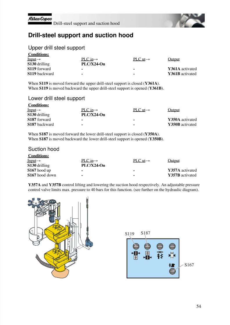
7/25/2019 Descripcion Roc Nva Cabina Roc d5-d7
http://slidepdf.com/reader/full/descripcion-roc-nva-cabina-roc-d5-d7 55/78
Drill-steel support and suction hood
54
Drill-steel support and suction hood
Upper drill steel supportConditions:Input → PLC in → PLC ut → OutputS130 drilling PLC/X24-OnS119 forward - - Y361A activatedS119 backward - - Y361B activated
When S119 is moved forward the upper drill-steel support is closed ( Y361A ).When S119 is moved backward the upper drill-steel support is opened ( Y361B ).
Lower drill steel supportConditions:Input → PLC in → PLC ut → OutputS130 drilling PLC/X24-OnS187 forward - - Y350A activatedS187 backward - - Y350B activated
When S187 is moved forward the lower drill-steel support is closed ( Y350A ).When S187 is moved backward the lower drill-steel support is opened ( Y350B ).
Suction hoodConditions:Input → PLC in → PLC ut → OutputS130 drilling PLC/X24-On
S167 hood up - - Y357A activatedS167 hood down - - Y357B activated
Y357A and Y357B control lifting and lowering the suction hood respectively. An adjustable pressurecontrol valve limits max. pressure to 40 bars for this function. (see further on the hydraulic diagram).
S119 S187
S167

7/25/2019 Descripcion Roc Nva Cabina Roc d5-d7
http://slidepdf.com/reader/full/descripcion-roc-nva-cabina-roc-d5-d7 56/78
Options
55
Options
Watermist system (option)Conditions for preset water flushing with automatic activation:Input → PLC in → PLC ut → OutputS130 drilling PLC/X24-OnS180 compressor activated - - Y6A activatedS448 centre position - - Y112A activated
Conditions for full water flushing with manual activation:Input → PLC in → PLC ut → OutputS130 drilling PLC/X24-OnS180 compressor activated - - Y6A activatedS448 forward position - - Y112B activated
Conditions for stopping water flushing:Input → PLC in → PLC ut → OutputS130 drilling PLC/X24-OnS180 compressor activated - - Y6A activatedS448 off position - - Y112A/B activated
The water mist system is used to stabilise the drilled hole when drilling through loose and porous rockby adding water to the air flushing. In general a small amount of water is used to dampen the cuttingsand bind them together into larger particles, for dust control, or to bind the dust to the hole wall toobtain better hole stability. The quantity of water is controlled by two directional valves and a flowregulator, as follows:
Full water supply is only used at short intervals to flush the water on dry clay to obtain sludge
which can be used for better stabilisation. The directional valve Y112B is open/activated. The watermist system: When directional valve Y112A is open and Y112B is closed, the amount of
water is controlled by an adjustable throttle valve (see figure). OFF : Both directional valves, Y112A and Y112B , are closed.

7/25/2019 Descripcion Roc Nva Cabina Roc d5-d7
http://slidepdf.com/reader/full/descripcion-roc-nva-cabina-roc-d5-d7 57/78
Options
56
Pressure relief valveWater tank
Shut off valve
Y112AY112B
Throttle valve
Y112AY112B
See full diagram for other details
No.: 9840 0423 22 page 2(3)
If a larger quantity of water needs to be added, for example when reaching a pocket of clay, full waterflushing can be selected ( S448 ) on the right-hand control panel. To avoid suction hoses and dustcollector filters clogging during the use of the water mist system the DCT must be switched off whenthe dust is very wet or if water is spurting up from the hole.

7/25/2019 Descripcion Roc Nva Cabina Roc d5-d7
http://slidepdf.com/reader/full/descripcion-roc-nva-cabina-roc-d5-d7 58/78
Options
57
Winch (Remote control box, option)Conditions for using the winch:
S130 must remain in position for tramming Remote control box ( A60 ) must be activated. Make sure the switch in the cab and the switch on
the box are in position for remote control. Make sure the winch switch is in the correct position ( S172 ). Use the winch motor switch ( S173 ) to reel the cable in and out.
Or The winch can be automatically activated by using the tramming levers on the remote control box.
See the operator's manual for instructions on activation and deactivation
The winch's hydraulic circuit includes functions for reeling in and out the cable, regulating the pullingforce of the winch and release of the winch brake.
The system has a protection device that protects the winch in the event of a fault. This is controlled byrelay S464 . When the protection device is activated ( CCU/114-On ), the winch in signal CCU/203 isblocked. Only the winch out function is possible
The remote control box has switches and controls forthe following functions:
Boom swing cylinder, Left/Right Boom lift cylinder, Up/Down Track oscillation cylinder, Up/Down Warning signal Winch, In/Out Winch power control Tramming, Left/Right Jacks, In/Out Winch/Tramming, Low/High Emergency stop; Fault LED;
activation/deactivation of remote control box
S500

7/25/2019 Descripcion Roc Nva Cabina Roc d5-d7
http://slidepdf.com/reader/full/descripcion-roc-nva-cabina-roc-d5-d7 59/78
Options
58
Winch blockThe winch's hydraulic circuit includes functions for reeling in and out the cable, regulating the pullingforce of the winch and release of the winch brake and plunger. The block comprises solenoid valveY209 (controls brake disc release), Y215 (activates tramming with winch), Y224 (controls the winchplunger), two pressure relief valves that limit the maximum pressure ( 125 bar ), a remote-controlledproportional pressure relief valve ( Y214 ) for controlling the pulling force, and Y208A (winch in) andY208B (winch out) which are control valves for the directional valve.
Solenoid valves Y208A and B control the directional valve (see figure) as follows:
Unreeling the cable: Solenoid valve Y208B and brake release valve Y209 are activatedsimultaneously by switch S173 on the remote control box. Unwinding can also be done manually withswitch S500 , which activates valve Y224 to release the winch plunger.
Reeling in the cable: Solenoid valve Y208A and brake release valve Y209 are activatedsimultaneously, either manually by using switch S173 or automatically which happens when the rig is
trammed from the remote control box. Manual: Switch S173 activates the valves abovementioned valves and closes the flow to theproportional relief valve Y215 . Subsequently, the pressure is being limited to 125 bar by oneof the pressure relief valve. (See figure)
Automatic: Solenoid valves Y208A and Y209 are activated automatically when the tramminglever on the remote control box is operated (forward or backward). Valve Y215 is activatedfor tramming with the winch. A counter pressure builds up (manually set on Y214 + springforce) that helps open pressure relief valve (A) to the tank. The pressure is then determined bythe remote controlled proportional pressure relief valve ( Y214 ). This relief valve is adjustedmanually with the potentiometer on the remote control box.
Y209 Y224 Y208A
Y215 Y214 Directional valve
Y208BY209 Y224 Y208A
Y215 Y214 Directional valve
Pressure relief valves
Y208B
Multi-discbrake
Plunger catch
A
P u m p
3
w i n c h / p o s .
P u m p
3
w i n c h / p o s .
See full diagram for other details
No.: 9840 0423 56 page 5(16)
Automatic reeling Manual reeling in

7/25/2019 Descripcion Roc Nva Cabina Roc d5-d7
http://slidepdf.com/reader/full/descripcion-roc-nva-cabina-roc-d5-d7 60/78
Options
59
Boom swing and boom lift cylinderThe adjacent switches are located on the remote control box andcontrol boom swing and boom lift, as well as activate the associatedsolenoid valves Y426 and Y425 . (See hydraulic diagram for details.)
Track oscillationThe adjacent switches are located on the remote control box andcontrol track oscillation left and right, as well as activate the associatedsolenoid valves Y419 and Y420 . (See hydraulic diagram for details.)
Note: The track lock is locked/unlocked from the left-hand armrest inthe cab.
Manual winch controlConditions for using the winch only:
Winch switch S172 in position ON
When switch S173 is used, the tramming controls are locked and thefollowing solenoid valves activated:
Brake valve (reversing valve that controls the brake) Y209 Winch motor valve Y208
Tramming without winchFunctions that are activated:
Switch S172 must be in tramming position.
Tramming controls (see following) activate solenoid valves Y206 and Y207 .
Tramming with winchWhen tramming with the winch, switch S172 must be in the winch position, which in turn activatesthe following functions:
Brake valve Y209 is activated. Winch motor valve Y208A is activated.
Tramming direction valves Y206 and Y207 are activated.
Note: All valves can be found on the corresponding block diagrams.
Boom lift Boom swing
Left Right
S172
S173
(On)

7/25/2019 Descripcion Roc Nva Cabina Roc d5-d7
http://slidepdf.com/reader/full/descripcion-roc-nva-cabina-roc-d5-d7 61/78
Options
60
Extraction unit (option)The extractor unit is used when the rock conditions vary a lot and there is a large risk of jamming. Thefunction of the extractor unit is to provide reverse percussion to the shank adapter and thus the drillsting and drill bit. The shank adapter for rock drills equipped with an extractor unit has a special
flange that receives the reverse percussion force. Since the shank adapter is pressed into the rock drillby the feed force during normal drilling, it works without the flange meeting the extractor piston.
Conditions for extraction unit: The rig must be in drilling mode. Percussion must be activated.
For the extraction unit to be activated the above conditions must be fulfilled. When there is a risk ofdrill jam, activate drill feed backward. The pilot pressure then activates the QDS-L valve and thepump pressure is directed via a restrictor valve (ø2,0) to the extraction unit. (See figure)
QDS-L
Throttle valve
Pump 1
Y178B
See full diagram for other parts
No.: 9840 0423 56 page 3(16) No.: 9840 0423 56 page 2(16)

7/25/2019 Descripcion Roc Nva Cabina Roc d5-d7
http://slidepdf.com/reader/full/descripcion-roc-nva-cabina-roc-d5-d7 62/78
Options
61
ECG, thread lubrication with oil (option)The ECG pump Y107 starts to pump as soon as the air flushing is turned on. The pump receives pulsesfrom the ECG module in the electric cabinet. ECG injects a small amount of lubricating oil into the airflushing. The oil creeps along the walls of the flushing hole and out into the threaded joints. Atlas
Copco recommends the use of COP OIL for all ECG and ECL lubrication.
Conditions:Input → PLC in → PLC ut → OutputS130 drilling PLC/X24-OnB118 arm in carousel PLC/X3-OnS100 reduced/full air flushing PLC/X26 or X25-On
PLC/Y23 or / and Y22-On Y116 or/and Y115 activated
S446 air flushing activated PLC/X27 or X30-On
PLC/Y1-On Y107 activated
Thread lubrication with grease brushes (option)Conditions for thread lubrication:Input → PLC in → PLC ut → OutputS130 drilling PLC/X24-OnS449 in automatic pos. - -S111 arm to drill centre PLC/X16-On PLC/Y10-On Y301B activated
K449 activated → Y552 activated
Conditions for manual thread lubrication:S449 in manual position → Y552 activated
Conditions for stopping thread lubrication:S449 in Off position → Y552 deactivated
Note : When S449 is in manual mode, 24V is fed directly to the thread lubrication valve ( Y552 ).
KC50218 18W50A
17
KC5018 26
KC5026
KC50226W50A
23
2 6 K C50 2- 26
K449
11 14
12
22/6B4
X30:44 Y552
1
Y552A1 A2KC301-3 3
KC3013 W30
Gy
X136KC502-18
S449A1
B5
B6
H0A
50
24V
K449 Y552
S449

7/25/2019 Descripcion Roc Nva Cabina Roc d5-d7
http://slidepdf.com/reader/full/descripcion-roc-nva-cabina-roc-d5-d7 63/78
Options
62
FunctionThe drill steel threads are lubricated with two brushes (A) located on the lower part of the feed beam,between the carousel and drill steel support. The drill steel passes these prior to threading.
A a
b
c
ab c
d
The grease is supplied by a pump placed in the front of the wagon frame. The pump is powered bycompressed air from the rig’s compressor and controlled through solenoid valve Y552 .Activation of Y552 can be done either automatically or manually and is controlled by the switch S449on the diesel panel.
Operation Under normal conditions, the system operates automatically. The
lubricant pump is activated when the rod handling process is inposition to move a drill steel to drill centre (tight grip). The result is
that every time a drill steel is removed from the carousel, a quantityof lubricant is pumped into the brushes that the threads of the drillsteel pass through.
If further lubrication is required, the system can be operatedmanually. In such a case, the lubricant pump is activated so long asthe switch S449 is kept in position (a).
If thread lubrication is not required, the system can be switched offby putting switch S449 in position (c).
The maximum pressure to the pump is adjusted to 7.5 bars by thepressure regulator 3. (See right figure) The system can be switched offby blocking the air supply with ball cock valve 8 or by the electricalswitch on the diesel panel.
We recommend the use of Atlas Copco Secoroc thread lubricant A forthe lubrication of drill steel threads.
See full diagram for other parts No.: 9840 0423 22 page 3(3)

7/25/2019 Descripcion Roc Nva Cabina Roc d5-d7
http://slidepdf.com/reader/full/descripcion-roc-nva-cabina-roc-d5-d7 64/78
Adjustment/calibration
63
Adjustment/calibration
Adjustable parameters, DCT Pulse duration - length of the pulse, i.e. the signal time Pause time - time between pulses Cleaning time - total time of the cleaning cycle (after drill stop).
To adjust the above times the conditions for the DCT must be fulfilledBasic conditions for adjusting DCT times:Input → PLC in → PLC ut → OutputS130 drilling PLC/X24-On - Y250 activatedB118 arm in carousel PLC/X3-OnS100 red./full air flushing PLC/X26 or X25-OnS446 percussion activated PLC/X27 or X30-On PLC/Y23 or / and Y22-On Y116 or/and Y115
activated
S181 activated PLC/X2-On PLC/Y21-On Y253 activatedS456 decrease/increaseDCT time
PLC/X4-Off (decrease) or On (increase)
Conditions for adjusting Pulse time:1. The basic conditions for adjusting the DCT must be fulfilled2. S457 activated → PLC / X5 -On → increases/decreases* the pulse time with 50ms/ button
pressNote : Factory setting is 300 ms.
Conditions for adjusting Pause time:1. The basic conditions for adjusting the DCT must be fulfilled
2. S458 activated → PLC / X10 -On → increases/decreases* the pause time with 1s/ buttonpress.
Note : Factory setting is 5s.
Conditions for adjusting Cleaning time:1. The basic conditions for adjusting the DCT must be fulfilled2. S459 activated → PLC / X11 -On → increases/decreases* cleaning time with 5s/ button
press.Note : Factory setting is 30s.
* Depending on which setting is on S456 (decrease/increase)
S459S456 S457 S458
X4 X5 X10 X11
S456
S457
S458
S459
? ? ? ?
? ? ? ?
? ? ? ?
? ? ? ?
? ? ? ?
??
????????
A 1 B 1 1 5
1 6 1 8 A 2
t2
t1
? ? ?? ? ?? ??
? ? ? ?
? ? ? ?
? ? ? ?
? ? ? ?
? ?
? ?? ?? ? ? ?

7/25/2019 Descripcion Roc Nva Cabina Roc d5-d7
http://slidepdf.com/reader/full/descripcion-roc-nva-cabina-roc-d5-d7 65/78
Adjustment/calibration
64
Adjustable drilling parameters
RPCF
High impact pressure
High feed pressure
RPC-F system
Rotation speed
Low impact pressure
Low feed pressure
Threading pressure
Unthreading pressure

7/25/2019 Descripcion Roc Nva Cabina Roc d5-d7
http://slidepdf.com/reader/full/descripcion-roc-nva-cabina-roc-d5-d7 66/78
Search list
65
Search list
Sensor: B118 RHS arm to carousel
B122 Rapid feed (+) stop B126 Rapid feed (-) stop B127 Rapid feed (-) stop/reduced speed upper B128 Pause/Start - Unthreading B134 Rotation pressure B142 Air flushing switch B143 Hydraulic oil level B174 Tramming, backward-left B175 Tramming, backward-right B182 Stop carousel rotation to grip B183 Stop carousel rotation from grip B262 Drill feed - backward B316 Laser sensor (Option) B352 Fuel level B360 Pressure switch, air filter (engine) B361 Cooling water level, Engine B362 Hydraulic oil tempterature B365 Pressure switch, air filter (Compressor) B366 Compressor temperature B367 Level switch (Option) B379 Sensor for Operator's seat B381 ECL collector - low B382 ECL collector - high B541 Condensor pressure switch
Lamps: H101 Lighting, A1 cabinet H102 Lighting, A1 cabinet H127 Hydraulic jack Out H129 Indicator lamp for winch H180 Compressor load H185 Warning, backward tramming (lamp + signal) H186 Warning, backward tramming (signal) H203 Low hydraulic oil level H207 Clogged air filter for diesel engine and compressor
H211 Alarm lamp for diesel engine monitoring H212 Alarm lamp for diesel engine monitoring – engine off H213 Alarm lamp for rig monitoring H214 Alarm lamp for rig monitoring – enging off H215 Engine coolant level H217 Engine heating H314 Working lights, valve plate H315 Working lights DCT H316 Working lights, rear right of roof H317 Working lights - roof left-hand rear side H322 Working lights, feeder H323 Working lights, feeder
H381 ECL collection low H382 ECL collection high

7/25/2019 Descripcion Roc Nva Cabina Roc d5-d7
http://slidepdf.com/reader/full/descripcion-roc-nva-cabina-roc-d5-d7 67/78
Search list
66
H511 Working lights, Cab-upper edge H512 Working lights, Cab-upper edge H513 Working lights, Cab-lower edge H514 Working lights, Cab-lower edge H515 Working lights-Cab
Relays: K1 Relay, air heater K4A Ignition relay K4B Ignition relay K4C Ignition relay K5A Start relay K5B Start relay K6 Open gripper relay K7 Loose grip relay K10 RHS-arm to drill centre relay
K11 RHS-arm to carousel relay K18 Filler pump relay K169 Drill stop – pilot pressure cut down K178 Rapid feed/threading relay K180 Hydraulic jack out K198A Relay work lights on feed K198B Relay rear work lights K213 Relay alarm lamp for rig monitoring K214 Relay alarm lamp for rig monitoring – enging off K330 Relay diesel engine enable K327 Relay lamp test ECL-collection K449 Relay brush greasing
Motors/pumps: M1 Starter motor M18 Filler pump (option) M20 Automatic lubrication system (option) M512 Wiper motor - right-hand side M516 Wiper motor - front side M517 Wiper motor - Roof M518 Water pump - front side M519 Water pump - Roof M520 Chair tipping
Potentiometers: R106 Potentiometer- Winch force R354 VDO contrast adjustment knob

7/25/2019 Descripcion Roc Nva Cabina Roc d5-d7
http://slidepdf.com/reader/full/descripcion-roc-nva-cabina-roc-d5-d7 68/78
Search list
67
Switches: S18 Switch, filler pump S100:1 Reduced air flushing S100:2 Full flushing S100:3 Air flushing off S111 Rod handling (multi-function lever) S113 Taking up steel S119 Upper drill steel support S130 Mode selector (drilling, tramming-positioning, hydraulic oil heating) S132A Emergency stop, winch S132B Emergency stop, Feeder S132C Emergency stop, cab S139 Ignition key S167 Suction hood S170 Switch, cab/remote control S172 Winch enable
S173 Winch (In/Out) S176 Track oscillation, left track S177 Track oscillation, right track S180 Compressor charging S181 DCT On/Off S182 Sleeve grippers S186 Warning signal S187 Lower drill steel support S189 Button, engine speed S209 Jacks (Out/In) S300 Battery switch S445 Track oscillation switch
S446 Percussion pressure, low/high S448 Water flushing (full/reduced) S449 Switch for lubrication with brushes S450 Scroll ECM display S452 Rapid feed/threading mode S453 Magnet off drill lever S456 DCT time, decrease/increase S457 Adjusting pulse time S458 Adjusting pause time S459 Adjusting cleaning time S464 Winch protection S500 Unlock winch S507 Working lights front, upper edge/lower edge S508 Working lights rear, right/left S509 Lighting- valve plate/DCT S515 Switch, cab door for lighting S520 Chair tipping S521 Water pump S525 Light cabin S526 Wiper, front S527 Wiper, roof S542 Timer, diesel heater

7/25/2019 Descripcion Roc Nva Cabina Roc d5-d7
http://slidepdf.com/reader/full/descripcion-roc-nva-cabina-roc-d5-d7 69/78
Search list
68
Resistors/contacts: R1 Resistor - inlet heater R241 Resistor - shutdown, PLC X41 R529 Seat heater (option) X535 connector socket
Valves: Y6A Compressor charging Y60 Cooler compressor (AC) Y101A Percussion flow Y101B Percussion pressure, low Y106 ECL pump Y107 ECG pump (option) Y109 Anti-jamming Y112A Watermist, automatic Y112B Watermist, manual
Y115 Air flushing, full flushing Y116 Air flushing, reduced flushing Y120 Preheating Y121 Tramming, main flow Y122 Tramming, high speed Y149 Rapid feed stop, backward Y150 Rapid feed stop, forward Y169 Pilot pressure Y170 Hydraulic tramming off Y178 Rapid feed/threading Y179 Drill mode magnets Y187 Pump 3 positioning/winch
Y206A Tramming, left forward Y206B Tramming, left backward Y207A Tramming, right forward Y207B Tramming, right backward Y208A Winch motor, In Y208B Winch motor, Out Y209 Winch brake, release Y210 Compressor load Y214 Variable winch force Y215 Max winch force Y224 Unlock winch Y250 DCT, fan motor Y251A DCT, filter clean A Y251B DCT, filter clean B Y251C DCT filter C Y253 DCT, outlet hatch Y300 Open gripper Y301A RHS arm to carousel Y301B RHS arm to drill centre Y303A Carousel rotation clockwise Y303B Carousel rotation anticlockwise Y306 Gripper claws, loose grip Y309 Sleeve grippers Y350A Lower drill steel support, open Y350B Lower drill steel support, closed Y357A Suction hood up

7/25/2019 Descripcion Roc Nva Cabina Roc d5-d7
http://slidepdf.com/reader/full/descripcion-roc-nva-cabina-roc-d5-d7 70/78
Search list
69
Y357B Suction hood down Y361A Upper drill steel support open Y361B Upper drill steel support closed Y410A Jack Up (Option) Y410B Jack Down (Option) Y419A Track oscillation, left Up Y419B Track oscillation, left Down Y420A Track oscillation, right Up Y420B Track oscillation, right Down Y425A Boom swing, left (Option with winch) Y425B Boom swing, right (Option with winch) Y426A Boom lift, Up (Option with winch) Y426B Boom lift, Down (Option with winch) Y473 Track oscillation, floating Y552 Lubrication brushes

7/25/2019 Descripcion Roc Nva Cabina Roc d5-d7
http://slidepdf.com/reader/full/descripcion-roc-nva-cabina-roc-d5-d7 71/78
07-08-03, PLC Programme, ROC D5,D7 Bosal
1(8)
PLC-PROGRAMME EXPLANATION
PLC TYPE : MITSUBISHI MELSEC FX1NPLC PART NUMBER :
E-EPROM PART NUMBER :
DRILLRIG TYPE : D5/D7 CAT-C7
1. GENERAL FUNCTIONS..............................................................................................................................................2 1.1 POWER SUPPLY ............................................................................................................................................................2 1.2 LAMP TEST ....................................................................................................................................................................2 1.3 PUMP 3 UNLOAD ..........................................................................................................................................................2 1.4 ACTIVATING ECM........................................................................................................................................................2 1.5 ENGINE CRANKING .......................................................................................................................................................2
2.DRILLING FUNCTIONS...............................................................................................................................................3 2.1. A DCT SUCTION ...........................................................................................................................................................3 2.1. B DCT CLEANING AFTER DRILLING ..............................................................................................................................3 2.2 ECL- PUMP ...................................................................................................................................................................3 2.3 ECG- PUMP ..................................................................................................................................................................3 2.4 ANTI -JAMMING ACTIVATED BY HIGH ROTATION PRESSURE ..........................................................................................4 2.5 ANTI -JAMMING ACTIVATED BY FLUSHING ....................................................................................................................4 2.6. A LOW FEED PRESSURE SETTING PUMP 1 .....................................................................................................................4 2.6. B LOW IMPACT ACTIVATION WITH FUNCTION SELF -HOLDING ......................................................................................4 2.6. C HIGH IMPACT ACTIVATION WITH FUNCTION SELF -HOLDING .....................................................................................5 2.6. D DEACTIVATION OF MAGNETIC HOLDING FOR DRILL LEVER .......................................................................................5 2.7 IMPACT HOUR COUNTER ...............................................................................................................................................5
3. RAPID FEED STOP FUNCTIONS.............................................................................................................................6 3.1. A FORWARD STOP AT DRILLSTEEL SUPPORT ................................................................................................................6 3.1. B BACKWARD STOP , AT UNCOUPLING ..........................................................................................................................6 3.1. C BACKWARD STOP , AT INTAKE MAGAZINE ..................................................................................................................6 3.1. D BACKWARD , MAX , STOP ...........................................................................................................................................6
4. RODHANDLING FUNCTIONS...................................................................................................................................6 4.1. A OPEN GRIPPER ..........................................................................................................................................................6 4.1. B LOOSE GRIP ...............................................................................................................................................................6 4.1. C HARD GRIP ................................................................................................................................................................6 4.2. A SLEEVE RETAINER ACTIVATION .................................................................................................................................7 4.2. B SLEEVE RETAINER DEACTIVATION .............................................................................................................................7 4.3. A RHS, ARM TOWARDS DRILLCENTER .........................................................................................................................7 4.3. B RHS, ARM TOWARDS CAROUSEL ..............................................................................................................................7
4.4. A RHS, CAROUSEL ROTATION , CLOCKWISE . ................................................................................................................7 4.4. B RHS, CAROUSEL ROTATION , COUNTER CLOCKWISE . ................................................................................................8
5. SUPERVISION FUNCTIONS......................................................................................................................................8
5.1 LOW HYDRAULIC OIL LEVEL , ENGINE SHUTDOWN .......................................................................................................8 5.2 COOLANT LEVEL , ENGINE SHUTDOWN .........................................................................................................................8 5.3 CLOGGED AIRFILTE FOR DIESELENGINE AND COMPRESSOR , WARNING .......................................................................8
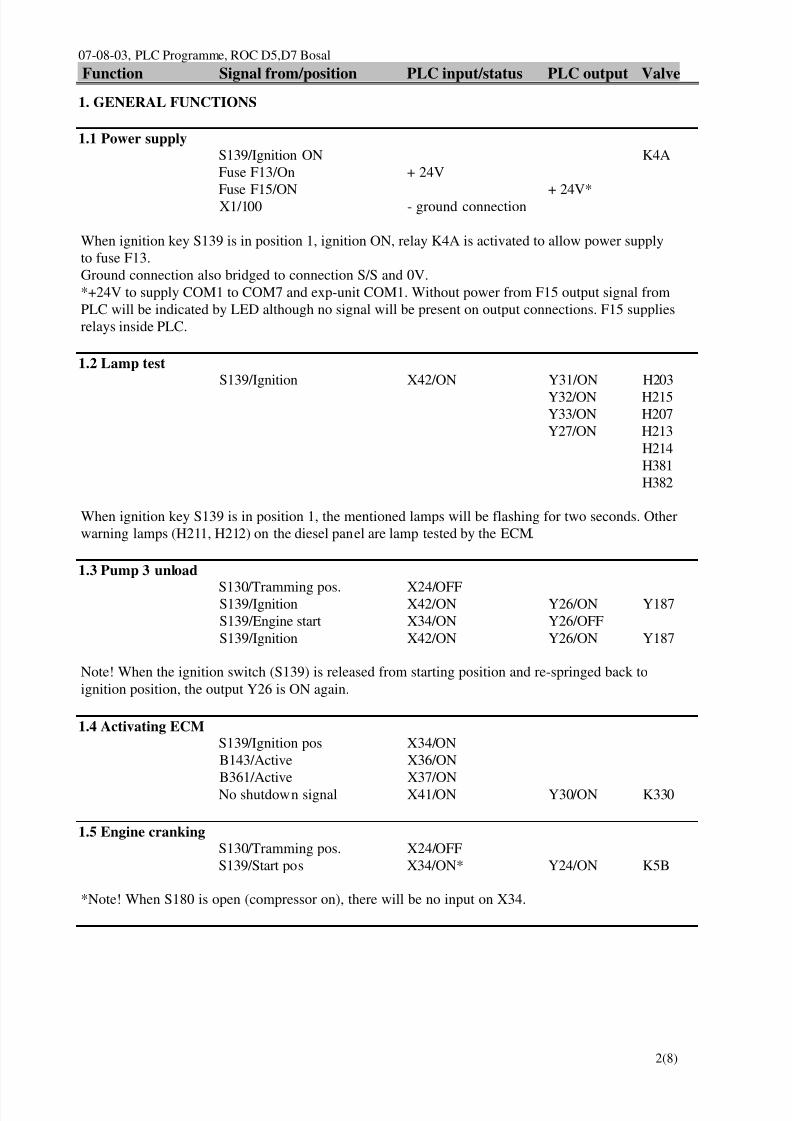
7/25/2019 Descripcion Roc Nva Cabina Roc d5-d7
http://slidepdf.com/reader/full/descripcion-roc-nva-cabina-roc-d5-d7 72/78
07-08-03, PLC Programme, ROC D5,D7 BosalFunction Signal from/position PLC input/status PLC output Valve
2(8)
1. GENERAL FUNCTIONS
1.1 Power supplyS139/Ignition ON K4A Fuse F13/On + 24V
Fuse F15/ON + 24V*X1/100 - ground connection
When ignition key S139 is in position 1, ignition ON, relay K4A is activated to allow power supplyto fuse F13.Ground connection also bridged to connection S/S and 0V.*+24V to supply COM1 to COM7 and exp-unit COM1. Without power from F15 output signal fromPLC will be indicated by LED although no signal will be present on output connections. F15 suppliesrelays inside PLC.
1.2 Lamp testS139/Ignition X42/ON Y31/ON H203
Y32/ON H215Y33/ON H207Y27/ON H213
H214H381H382
When ignition key S139 is in position 1, the mentioned lamps will be flashing for two seconds. Otherwarning lamps (H211, H212) on the diesel panel are lamp tested by the ECM.
1.3 Pump 3 unload
S130/Tramming pos. X24/OFFS139/Ignition X42/ON Y26/ON Y187S139/Engine start X34/ON Y26/OFFS139/Ignition X42/ON Y26/ON Y187
Note! When the ignition switch (S139) is released from starting position and re-springed back toignition position, the output Y26 is ON again.
1.4 Activating ECMS139/Ignition pos X34/ONB143/Active X36/ONB361/Active X37/ONNo shutdown signal X41/ON Y30/ON K330
1.5 Engine crankingS130/Tramming pos. X24/OFFS139/Start pos X34/ON* Y24/ON K5B
*Note! When S180 is open (compressor on), there will be no input on X34.

7/25/2019 Descripcion Roc Nva Cabina Roc d5-d7
http://slidepdf.com/reader/full/descripcion-roc-nva-cabina-roc-d5-d7 73/78
07-08-03, PLC Programme, ROC D5,D7 BosalFunction Signal from/position PLC input/status PLC output Valve
3(8)
2.DRILLING FUNCTIONS
2.1.a DCT suctionS130/Drilling pos. X24/ONB118/Arm in carousel X3/ON
S100/Flush air pos. X25/ON or X26/ON*S446/Flushing pos. X27/ON or X30/ONS181/Suction pos. X2/ON Y21/ON Y253
*To start flushing and DCT, press the impact switch (S446A) for shorter than 0.5 sec. To start lowimpact, press the switch (S446A) for longer than 0.5 sec. To start high impact without self holding, pressthe switch (S446B) all the time.
2.1.b DCT cleaning after drillingS130/Drilling pos. X24/ON*S100/Flush air pos. X25/OFF or X26/OFF*S446/Flushing pos. X27 OFF or X30/OFF Y21/OFF Y251A
Y251BY251C
*To achieve cleaning, the first condition is to have the DCT suction on, Y21/ON (see 2.1a).The second condition is Y21 must be then be OFF (DCT hatch closed) by having one of: X25, X26,X27, X30 OFF. Just by switching off S181 will not start DCT cleaning; in other words, to start DCTcleaning, drilling must be deactivated. If DCT hatch is not ON from the beginning (Y21/OFF), then nocleaning will be achieved at all.
2.2 ECL-pumpS130/Drilling pos. X24/ON
B118/Arm in carousel X3/ONS100/Flush air pos. X25/ON or X26/ON*S446/Flushing pos. X27/ON or X30/ON Y0/ON Y106
*To start flushing and DCT, press the impact switch (S446A) for shorter than 0.5 sec. To start lowimpact, press the switch (S446A) for longer than 0.5 sec.Note! The ECL-Pump (Y106) works with an extended time of 60 seconds when the flush air switchS100 or impact switch S446 have been shut-off after drilling. This time is set on the external ECL-relayand is not affected by a lost in output signal Y0.
2.3 ECG-pump
S130/Drilling pos. X24/ONB118/Arm in carousel X3/ONS100/Flush air pos. X25/ON or X26/ON*S446/Flushing pos. X27/ON or X30/ON Y1/ON Y107
*To start flushing and DCT, press the impact switch (S446) for shorter than 0.5 sec. To start low impact,press the switch (S446) for longer than 0.5 sec.Note! The ECG-pump (Y107) does not work with an extended time. But it is possible to adjust on theexternal ECG-relay if needed.
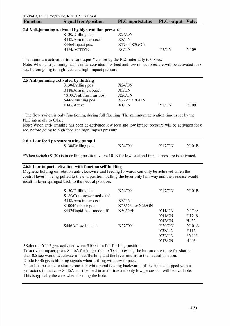
7/25/2019 Descripcion Roc Nva Cabina Roc d5-d7
http://slidepdf.com/reader/full/descripcion-roc-nva-cabina-roc-d5-d7 74/78
07-08-03, PLC Programme, ROC D5,D7 BosalFunction Signal from/position PLC input/status PLC output Valve
4(8)
2.4 Anti-jamming activated by high rotation pressureS130/Drilling pos. X24/ONB118/Arm in carousel X3/ONS446/Impact pos. X27 or X30/ONB134/ACTIVE X0/ON Y2/ON Y109
The minimum activation time for output Y2 is set by the PLC internally to 0.8sec.Note: When anti-jamming has been de-activated low feed and low impact pressure will be activated for 6sec. before going to high feed and high impact pressure.
2.5 Anti-jamming activated by flushingS130/Drilling pos. X24/ONB118/Arm in carousel X3/ON*S100/Full flush air pos. X26/ONS446/Flushing pos. X27 or X30/ONB142/Active X1/ON Y2/ON Y109
*The flow switch is only functioning during full flushing. The minimum activation time is set by thePLC internally to 0.8sec.Note: When anti-jamming has been de-activated low feed and low impact pressure will be activated for 6sec. before going to high feed and high impact pressure.
2.6.a Low feed pressure setting pump 1S130/Drilling pos. X24/ON Y17/ON Y101B
*When switch (S130) is in drilling position, valve 101B for low feed and impact pressure is activated.
2.6.b Low impact activation with function self-holding
Magnetic holding on rotation anti-clockwise and feeding forwards can only be achieved when thecontrol lever is being pulled to the end position, pulling the lever only half way and then release wouldresult in lever springed back to the neutral position.
S130/Drilling pos. X24/ON Y17/ON Y101BS180/Compressor activatedB118/Arm in carousel X3/ONS100/Flush air pos. X25/ON or X26/ONS452/Rapid feed mode off X50/OFF Y41/ON Y179A
Y41/ON Y179BY42/ON H452
S446A/Low impact. X27/ON Y20/ON Y101AY23/ON Y116Y22/ON *Y115Y43/ON H446
*Solenoid Y115 gets activated when S100 is in full flushing position.To activate impact, press S446A for longer than 0.5 sec, pressing the button once more for shorterthan 0.5 sec would deactivate impact/flushing and the lever returns to the neutral position.Diode H446 gives blinking signals when drilling with low impact.Note: It is possible to start percussion while rapid feeding backwards (if the rig is equipped with aextractor), in that case S446A must be held in at all time and only low percussion will be available.This is typically the case when cleaning the hole.

7/25/2019 Descripcion Roc Nva Cabina Roc d5-d7
http://slidepdf.com/reader/full/descripcion-roc-nva-cabina-roc-d5-d7 75/78
07-08-03, PLC Programme, ROC D5,D7 BosalFunction Signal from/position PLC input/status PLC output Valve
5(8)
2.6.c High impact activation with function self-holdingS130/Drilling pos. X24/ON Y17/ON Y101B S180/Compressor activatedB118/Arm in carousel X3/ONS100/Flush air pos. X25/ON or X26/ONS452/Rapid feed mode off X50/OFF Y41/ON Y179A
Y41/ON Y179BY42/ON H452
S446A/Low impact. X27/ON Y20/ON Y101AY23/ON Y116Y22/ON *Y115Y43/ON H446
⇓⇓⇓⇓ ⇓⇓⇓⇓ ⇓⇓⇓⇓ ⇓⇓⇓⇓ S446B/High impact. X30/ON Y17/OFF
Y20/ON Y101AY23/ON Y116Y22/ON *Y115
Y43/ON H446
*Solenoid Y115 gets activated when S100 is in full flushing position.To shift to high impact from low impact, press S446B for longer than 0.5 sec, pressing the buttononce more or shorter than 0.5 sec would deactivate impact/flushing and the lever returns to theneutral position.When changing back to low impact, press the low impact pressure switch S446A for longer than 0.5sec, otherwise the impact will be shut off.Diode H446 gives stable signal when drilling with high impact.When starting directly with high impact, impact is activated as long as switch S446B is pressed.
2.6.d Deactivation of magnetic holding for drill lever
S453/Magnets off drill lever X51/ONORS452/Rapid feed mode X50/ON Y41/OFF
2.7 Impact hour counterS130/Drilling pos. X24/ONS446/Impact. pos. X27/ON or X30/ON Y20/ON P108

7/25/2019 Descripcion Roc Nva Cabina Roc d5-d7
http://slidepdf.com/reader/full/descripcion-roc-nva-cabina-roc-d5-d7 76/78
07-08-03, PLC Programme, ROC D5,D7 BosalFunction Signal from/position PLC input/status PLC output Valve
6(8)
3. RAPID FEED STOP FUNCTIONS
3.1.a Forward stop at drillsteel supportS130/Drilling pos. X24/ONB122/Active X12/ON Y4/ON Y150
3.1.b Backward stop, at uncouplingS130/Drilling pos. X24/ONS113/Take up rod string X22/ONB126/Active X13/ON Y3/ON Y149
3.1.c Backward stop, at intake magazineS130/Drilling pos. X24/ONS113/Take up rod string X22/ONB126/Active X13/ON Y3/ON Y149
3.1.d Backward, max, stopS130/Drilling pos. X24/ONB127/Active X14/ON Y3/ON Y149
If sleeve retainer switch (S182), X23/ON is activated then rapid feed stop backward (Y149), Y3/ON andrapid feed stop forward (Y150), Y4/ON will be automatically activated.
4. RODHANDLING FUNCTIONS
4.1.a Open GripperS130/Drilling pos. X24/ON*S446/Impact switch X27 and X30/OFF
B379/Operator seat active X31/ONS111/Top button pushed X21/ON Y6/ON K6 Y300
*Flushing is deactivated automatically when switching impact off, this enables rod handling.
4.1.b Loose gripS130/Drilling pos. X24/ON*S446/Impact switch X27 and X30/OFFB379/Operator seat active X31/ONS111/Neutral pos. All functions OFFB118/Dis-ACTIVE X3/OFF Y7/ON K7
Y306
*Flushing is deactivated automatically when switching impact off, this enables rod handling.
4.1.c Hard gripS130/Drilling pos. X24/ON
Hard grip is the normal condition. No active inputs or outputs are required.Exceptions are Open gripper and Loose grip.

7/25/2019 Descripcion Roc Nva Cabina Roc d5-d7
http://slidepdf.com/reader/full/descripcion-roc-nva-cabina-roc-d5-d7 77/78
07-08-03, PLC Programme, ROC D5,D7 BosalFunction Signal from/position PLC input/status PLC output Valve
7(8)
4.2.a Sleeve retainer activationS130/Drilling pos. X24/ON*S446/Impact switch X27 and X30/OFFB379/Operator seat active X31/ONS111/Pos, backwards. X16/ON**S182/Sleeve retainer X23/ON Y5/ON Y309
*Flushing is deactivated automatically when switching impact off, this enables rod handling.** Sleeve retainer activation is time delayed in PLC, to secure that the rod grippers are out in drill centrebefore activation.
4.2.b Sleeve retainer deactivationS130/Drilling pos. X24/ON*S446/Impact switch X27 and X30/OFF** S182/Sleeve retainer X23/OFF Y5/OFF
*Flushing is deactivated automatically when switching impact off, this enables rodhandling.**Rod gripper transportation to carousel is time delayed in PLC, to secure that the sleeve retainer is backin neutral position.
4.3.a RHS, arm towards drillcenterS130/Drilling pos. X24/ON*S446/Impact switch X27 and X30/OFFB379/ACTIVE X31/ONS111/Pos, backwards. X16/ON Y6 & Y7/OFF
Y10/ON K10 Y301B
*Flushing is deactivated automatically by switching of the impact which enables rodhandling.
4.3.b RHS, arm towards carouselS130/Drilling pos. X24/ON*S446/Impact switch X27 and X30/OFFB379/ACTIVE X31/ONS111/Pos, forward. X15/ON Y11/ON K11
Y301A
*Flushing is deactivated automatically by switching of the impact which enables rodhandling.
4.4.a RHS, carousel rotation, clockwise.S130/Drilling pos. X24/ON*S446/Impact switch X27 and X30/OFFB379/Operator seat active X31/ONS111/Top button pushed. X21/ONS111/Pos, to the left. X17/ONB118/ACTIVE X3/ON
START B183/ACTIVE X7/ON Y13/ON Y303A⇓⇓⇓⇓ B183/Dis-ACTIVE X7/OFF
STOP B183/ACTIVE X7/ON Y13/OFF
*Flushing is deactivated automatically when switching impact off, this enables rodhandling.

7/25/2019 Descripcion Roc Nva Cabina Roc d5-d7
http://slidepdf.com/reader/full/descripcion-roc-nva-cabina-roc-d5-d7 78/78
07-08-03, PLC Programme, ROC D5,D7 BosalFunction Signal from/position PLC input/status PLC output Valve
4.4.b RHS, carousel rotation, counter clockwise.S130/Drilling pos. X 24/ON*S446/Impact switch X27 and X30/OFFB379/Operator seat active X31/ONS111/Top button pushed. X21/ONS111/Pos, to the right. X20/ONB118/ACTIVE X3/ON
START B182/ACTIVE X6/ON Y12/ON Y303B⇓⇓⇓⇓ B182/Dis-ACTIVE X6/OFF
STOP B182/ACTIVE X6/ON Y12/OFF
*Flushing is deactivated automatically by switching of the impact which enables rodhandling.
5. SUPERVISION FUNCTIONS
5.1 Low hydraulic oil level, engine shutdownB143 off. X36/OFF *Y30/OFF K330
**Y31/ON H203*Note! Output Y30 located at Y0 on the extention unit (slave unit).**Note! Output Y31 located at Y1 on the extention unit (slave unit).When K330 is deactivating the power supply from fuse F12 to the ECM-control module, the engineshuts down.
5.2 Coolant level, engine shutdownB361 off. X37/OFF Y30/OFF K330
*Y32/ON H215
*Note! Output Y32 located at Y2 on the extention unit (slave unit).When K330 is deactivating the power supply from fuse F12 to the ECM-control module, the engineshuts down.
5.3 Clogged airfilte for dieselengine and compressor, warningB360 or B365 on. X40/ON *Y33/ON H207
*Note! Output Y33 located at Y3 on the extention unit (slave unit).