depth, maximum bending moment, and tie-rod load. The ...
60
CHAPTER 5 DESIGN OF THE BULKiKLD SYSTEM Bulkhead design zequires more than determining penetration depth, bending moment, and tie-rod load. External loads must be considered and.the structural components must be designed keeping in mind the cost effectiveness of various construction materials. External loads include surchargesimposed upon the backfill, hydrostatic imbalance in the backfill, ice-thrust, mooring loads, and impact loads. The struc- tural components, i.e., sheet, piles, tie-rods, wales, splices, and anchorages, must be dimensioned and detailed. The cost effectiveness of the entire systemrequires consideration of the strength, longevity, availability, and fastening methods of the component materials. 5.1. External loads must be accounted for when designing an earth retaining system as these l.oads will increase the required penetration depth, maximum bending moment, and tie-rod load. Theexternal loads that the designer must contend with are uniformly distributed loads, ooint loads, line loads, hydrostatic imbalance, ice thrust, mooring pull, and impact loads, Other environmentalloads are discussedby Hubbell and Kulhawy 979!. 140
Transcript of depth, maximum bending moment, and tie-rod load. The ...
CHAPTER 5
DESIGN OF THE BULKiKLD SYSTEM
Bulkhead design zequires more than determining penetration depth,
bending moment, and tie-rod load. External loads must be considered
and. the structural components must be designed keeping in mind the
cost effectiveness of various construction materials. External loads
include surcharges imposed upon the backfill, hydrostatic imbalance in
the backfill, ice-thrust, mooring loads, and impact loads. The struc-
tural components, i.e., sheet, piles, tie-rods, wales, splices, and
anchorages, must be dimensioned and detailed. The cost effectiveness
of the entire system requires consideration of the strength, longevity,
availability, and fastening methods of the component materials.
5.1.
External loads must be accounted for when designing an earth
retaining system as these l.oads will increase the required penetration
depth, maximum bending moment, and tie-rod load. The external loads
that the designer must contend with are uniformly distributed loads,
ooint loads, line loads, hydrostatic imbalance, ice thrust, mooring
pull, and impact loads, Other environmental loads are discussed by
Hubbell and Kulhawy �979!.
140

5. 1.1. Uni.f orml Distributed Loads
Uniformly distributed loads are easily dealt with. The horizontal
stress, ph, resulting from a surcharge, q force/unit area!, is given by
�-1!
in which K the active stress coefficient. The resulting stress dis-a
tribution is rectangular Figures 2-6 and 4-1! . The resultant forces
are then incorporated into the equilibrium calculati,ons for penetration
depth and tie-rod loads.
When the design charts are used, the surcharge can be converted
into an equivalent height of soil, h , given byeq
�- Za!yl
in which y the unit weight of soil comprising the backfill. The1
equivalent height of soil is merely added to the free standing wall
height, H, and the resulting dimension is used throughout the computa-
tions. An example is given in the Appendices.
5.1.2. Point and Line Loads
The effects of point and line loads are treated in a semi-
empirical manner Terzaghi, 1954!. Elastic theory, as expressed in the
Boussinesq equation, was modified by experimen.t and the results given
as in Figure 5-l. Knowing the intensity of the surcharge load, the
designer uses the formula shown to compute the resultant horizontal
force, P, . The point of application is then -ound by choosing the
appropriate dimension L for the corresponding value of m. in Figure 5 � ib
and the computations may proceed.

142
eH P00 ~ form 0.4!Qg 4H �.16+ n' I
PH ~ 0,55Qq, resultant force
form! 0.4!m'n
m + n~!
p ~ reeo feof force0.64QpH m +1j
a. Horizontal stress due to line load geng, 1962, p. 89!
0!
00 ~ elPf.
b. Horizontal stress due to point and line load VavalFacilities Engineering Command, p. 7-lO-10!
Figure 5-1. Surcharge loads

143
Q,eH 0.28 for m ~ 0 4!H~ �.16 + n~!~
PH ~ 0.78 � see Fig. 11!QpH
Qp rsvp n'aH ~ 1.77 for m > 0.4!
P m' + n'!'
FH ~ 0.45 � eee F!9. t1!QpH
Ehesthn View
c. Horizontal stress due to point load Teng, 1962, p. 91!
aP + eos4RK n g g!
d. Horizontal stress due to point load Teng, 1962, p. 91!
Figure 5-1. Continued

144
When the design charts are used., an equivalent height of soil is
employed in a manner similar to the uniformly distributed case. For
point and line loads,
P
hH
eq y H-L!�-2b!
5.1.3. H drostatic and See a e Effects
Fills containing significant amounts of soils of low permeability,
such as clay, silt or fine sand, may cause a hydrostatic imbalance.
Rapid tidal changes or substantial precipitation will cause saturation
of the fill above the water level and, because of the low permeability
of the fill, a hydrostatic imbalance results. The proper analysis of
this condition calls for the use of a flow net Figure 5-2a! . If the
soil is relatively homogeneous, an approximation of the pressure dis-
tribution as illustrated in Figure 5-Za Terzaghi, 1954! may be used.
As indicated by the flow net, the passage of water under the toe of
the bulkhead has an upward gradient on the dredge side of the wall.
The net result of this upward f1ow of water is a reduction of the
effective unit weight of the soil, hy. The relationship between the
hydrostatic imbalance H and reduced unit weight are shown in Figureu
5- 3 and described by the relationship
in which: H the free standing wall height, and L ~ the distance from
the dredge level to the point of application of PH. The free standing
wall height is then adjusted by increasing the dimension by h , Designeq
examples are given in the Appendices.

145
Figure 5-2. Hydrostatic and seepage stresses Terzaghi, 1954, p. 1243!
tll
o Vekeaa af�D
Figure 5-3. Reduction of effective unit weight TerzagM, 1954, p. 1243!

146
hy pcf! 20�D
�-3!
The reduced unit weight of the soil is then used for passive stress
computations.
5.1.4. Ice Thrust
5.1.5. Aoorin and Shi Tm act
Loads associated with mooring pull can be assumed to be equal to
the capacity of the winch used on the boat Teng, 1962! .
Ship impact loads are usually too high to design for. As an
alternative, a fendering system should be installed to minimize the
amount of impact.
Ice thrust is * phenomenon which occurs when there is ground water
or capillary water above the frost line. Horizontal thrust is the re-
sult of volume expansion of ice upon temperature change. Horizontal
loads due to ice thrust are often too large to be designed. for and should,
therefore, be eliminated by employing free draining soils for fill
material Teng, 1962!.
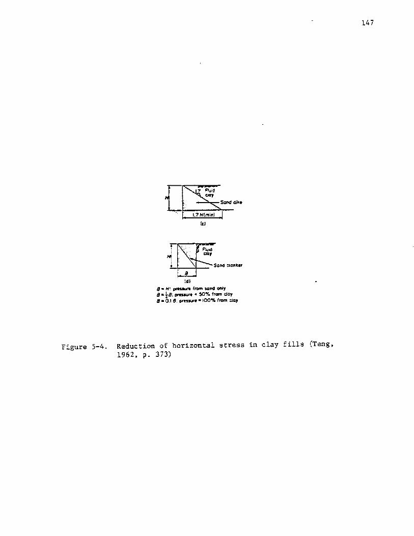
Zn addition to reducing large lateral loads due to cohesive ma-
teri.al in the backfill, sand dikes or sand blankets Figure 5-4! can
be incorporated to eliminate the potential for ice thrust and hydro-
static imbalance. A. backfill consisting of clean, coarse-grained soil
is highly permeable and precludes any significant capillary action in
the intergranular voi,ds.
147
dike
and blansH
d!8 ~ H: pressure rara sand paly8 ~ g8,' ptessale s 50% fnnn aiay8 0.> 8: mme iaa 4 rnnn a>ay
Figure 5-4. Reduction of horizontal stress in clay fills Teng,1962, p. 373!
148
5.1.6. Load Factors
Load factors are employed to provide an adequate safety margin
in cases where the extent of variations in the actual loading are un-
known. Such a situation occurs when tie-rods are employed.
Tie-rod loads may be higher than the values calculated for a
number of reasons. Settlement of the fill, or soft soil in the sub-
grade, causes the tie-rods to sag. This additional elongation is
accompanied by an increase in stress.
Such overstressing could be eliminated by installing the tie-rod
within a PVC pipe. As the soil beneath the pipe settles, the pipe
moves, but not the tie-rod Teng, 1962!,
Tie-rods may also become overstressed because of improper con-
struction methods, i.e., placing the backfill unevenly, compacting the
backfill, surcharging the backfill without first calculating the
effect, or overtightening the tie-rod.
Since tie-rods are susceptible to overstressing, the loads on
tie-rods should be increased by 1.2 in cases where the designer is
reasonably assured of little overstressing, and by 1.4 in cases where
the designer is uncertain.
Load factors need not be applied to penetration, sheet pile
anchorage, wale, or splice calculations. The safety factor used in
penetration calculations Equation 3-1! accounts for any variation in
direct soil stresses acting upon the wall. Although the unfactored
soil parameters are used to compute bending moment in sheet piles,
the values are still conservative. Additionally, allowable loads in
materials are substantially lower than failure loads.
Although load factors are not applied to penetration depths,
an increase in penetration must be applied to prevent fsi,lure from
overdredging and scour. In such cases, the designer arbitrarily in-
creases the penetration depth based upon local codes or the amount
of scour and overdredging that the designer considers likely to occur.
5.2. Cost Effectiveness
The optimum design is that which is the most economical and
performs the desired function for a specified lifetime, i.e., it is
the most cost effective system. To attain this, the designer must
consider the wall types, anchorage types, materials, and fastening
methods available.
The discussion regarding materials is limited to steel and timber,
as these comprise the majority of bulkheads. Reinforced concrete has
been used for bulkheads. However, its use is often too costly for
smaller walls and the complexity of the design procedure places its
treatment beyond the scope of this work. Other structural materials,
such as aluminum, are also available.
High strength bolts for steel walls, common bolts and nails for
wood walls, and turnbuckles for tie-rods are the fasteners which will
be discussed.
5. 2.1.
5.2.1.1. Anchored Wall vs. Cantilevered Wall
It may be advantageous to employ a cantilevered wall system when
the standing wall height is small or when some aspect of the site pre-
cludes the installation. of an anchorage. For example, the cost of

150
utilizing an anchorage, with the required wales, tie-rods and conn.ectors,
may be higher than the cost of the increased depth of penetration re-
quired for a cantilevered wall; or, a utility line may be located
which prevents employment of an anchorage. Use of the simplified design
method facilitates the economic comparison between an anchored wall
and a cantilevered wail in such cases.
A frequent sight along waterfronts is a structure corrrmonly re-
ferred to as a navy bulkhead. It is characterized by wooden sheet pile
members employed in conjunction with eight in �03 mm! diameter wooden
timber piles Figure 5-5!. This structure gives the appearance of
increased resistance to lateral loads when compared to smooth-faced
bulkheads. The addition of the eight, in, �03 mm! piles does provide
added strength, but the flexibility of the system is decreased and the
interaction between the soil and structure is affected.
A qualitative analogy can be inferred from the discussion in
Chapter 2 regarding a soldier pile and lagging system Tsui, 1974!.
The soldier pile is very stiff as compared to the lagging and this is
roughly analogous to the stiffness of an S in �03 mm! pile relative to
the stiffness of the sheet piles. As shown by the finite element
analysis of the discontinuous walls Figure 2-21!, the displacement.
of the lagging was two times that of the soldier piles for softer soils,
and 1.5 times for stiffer soils. When deflections of an equivalent,
continuous planar wall were computed, it was found that the displacement
for the lagging was 1.6 times greater for the sorter soils and 1.3
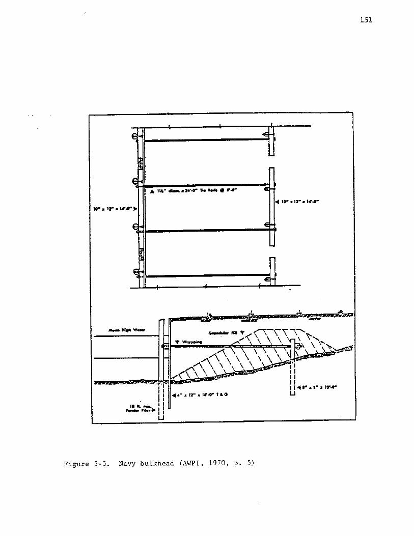
Figure 5-5. Navy bulkhead AWPI, l970, y. 5!
times greater for stiffer soils. One can therefore suggest that similar
behavior occurs for the navy bulkheads. In other words, deflectioas,
and therefore bending momeats and bending stresses, are substantially
greater at the midpoint between ewo piles than at the piles themselves.
As previously mentioned, the flexibility criteria for bulkhead
design is determined by the flexibility number, p:
�-15!pEI
I1 3
12�-<!
in which: b ~ member width, and t = thickness. With the addition of an
S in �03 mm! pile, the moment of inertia is greatly increased and can
be determined utiliziag the parallel axis theorem:
I I +A d + I2+A2d22 2
in which: l and I2 = moment of inertia of sections 1 and 2, Al and A2
= cross sectional areas of sections 1 and 2, and dl and d~ = distance
from the neutral axis to the centroids of sections 1 and 2. For the
in which: H total sheet pile length, E ~ elastic modulus of the
members, and I ~ moment of inertia per unit length of wall Rowe, 1952!.
A brief investigation of varying member sizes leads to the essence
of pile flexibility with respect to navy bulkheads. With total sheet
pile length and the elastic modulus held constant, the governing factor
determining wall flexibility is the momeat of inertia. For rectaagular
members,
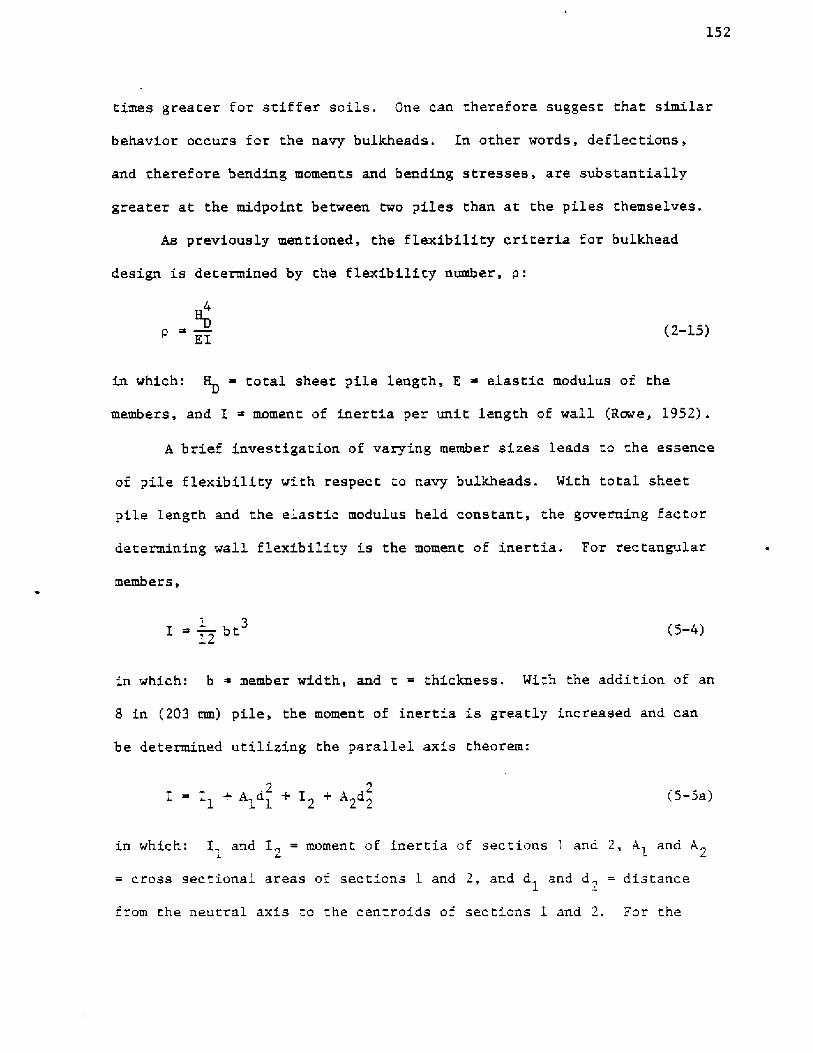
navy bulkhead Figure 5-6!:
I � r ~ 201 in 8.37 x 10 mm !4 7 4
1 4�-5b!
I ~ � i t1 3
2 12 s'�-Sc!
Al ~ r 50.3 in �.24 x 10 mm !,2 2 4 2 �-5d!
A2~2, t �-5e!
1d c � � t, and
1 2 s'�-5f !
d ~ t +t +4 � c in! ~ t +t +10.2 � c mm!2 s w s w
�-5g!
in which Iz. length of wall under consideration, c distance to the
neutral axis, t ~ thickness of sheet pile, and t = thickness of thes w
wale. Noments of inertia and planar, equivalent moments of inertia were
computed and are given in Table 5-1 for varying combinations of sheet
pile thickness, wale thickness and lengths of wall. Tt is obvious
that the presence of the 8 in �03 mm! pile adds considerably to the
stiffness of the system, even when a planar equivalent is computed with
a distance of 7 ft �13 m! between 8 in �03 mm! piles.
The effect of the increased stiffness, or decreased flexibility,
on bulkhead design can be appreciated when selecting sheet pile thick-
ness. The values of critical pile flexibility, o , defined as the
minimum flexibility to permit moment reductions based upon Free Earth
Support computations are
154
Figure 5-6. Dimensions of navy bulkhead
155
tW
inches
ts
inches
I
in /ftI4
in !c
inchesinches
12
10
12
24
10
12
48
10
12
84
10
12
Na piles
4.16 x 10⁴
1 inNote: 1 in 25.4 mm1 ft = 0.305 R
»n44
ft1.37 x 10
II1
Table 5-1. Effect of 8 inch piles an flexibility
9. 799. 369.16
11. 15
10.53
10.18
12. 51
11. 70
7.65
7. 05
6.81
8.67
7.87
7.50
9.70
8.69
8,19
5.46
4.99
4.90
6.15
5. 51
5. 32
6.80
6.03
5. 73
3. 99
.374
3.82
4.45
4.08
4.08
4. 92
4.41
4.34
1.0
1.5
2.0
295440515077
38645270
6550
4903
6652
4367
5650
6795
574 2
73678775
7310
8040
11,0205809
7100
8265
7656
9260
10,6559235
9320
13,3606796
8028
9219
8962
10,46011,84011, 44012,06015,560
2954
4050
50803860
5270
6550
4900
6650
2180
2830
3400
2870
36804390
3660
4020
5510
1450
1180
2070
1910
2320
2660
2310
2330
3340
970
1150
1320
1280
1490
1690
1630
1720
2220
8
27
64
l56
log p ~ -4.00 for dense sand, and
log p -3.50 for loose sand Rowe, l952!
These values correspond to pile lengths:
K = 19. 2 ft �.85 m! for dense sand, and
H ~ 25.6 ft �.80 m! for loose sand, for
4
I 970 l. 33 � ! >ft
the moment of inertia per unit, length of an equivalent, planar wall, with
t = 2 in �0.8 mm! ands
t S in �03 mm!.
It can therefore be concluded that. moment reduction should not be
allowed for navy bulkheads of moderate height. Zt should also be noted
that the planar equivalent should not be used for selecting sheet pile
thickness because bending stresses can be considerably higher at the
midpoint between S in �03 mm! piles than stresses computed for the
planar equivalent.
Although the analogy between the soldier pile and lagging wall and
the navy bulkhead is incomplete, it does suggest that a conservative
approach be used in designing navy bulkheads. The consequence of this
conservatism results in thicker sheet pile members and, therefore,
higher costs. The convenience of a built-in fendering system may not be
warranted because of this increased expense. However, large impact
loads caused by large ships or breaking waves may necessitate the added
cost or navy bulkneads.

LS7
5. 2. 2. Anchora e T e and Location
safe zone for anchorage location is outlined by segments ed and dc,
Figure S-8 represents the anchorage location for a sheet pile
length, H , of 17.5 ft �.33 m! and angle of internal friction, ], of
32 degrees, the geometry and soil parameter for example ffl. Point, "a"
marks the pile toe, and point "e" marks the intersection of line seg-
ment ae, inclined at an angle equal to > from the horizontal, with the
surface of the fill.
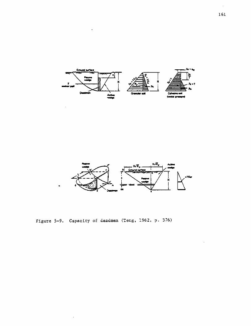
The capacity of a continuous deadman or sheet pile anchorage
force per unit length of anchorage!, is given by
�-6!P�=P -PALT p a
The anchorage may be deadmen, braced piles, sheet piles, or the
footings of large structures Figure 5-7!. The passive stress developed
in front of the anchorage determines the capacity of deadmen and sheet
piles. Foundation footings derive their capacity to resist horizontal
movement from the passive stress developed and from the friction de-
veloped along the bottom of the footing. Determination of pile capacity
is beyond the scope of this work. Methods for computing pile capacity
are given by Cheung and Kulhawy �981!.
The anchorage must be located so that it is not within the active
failure wedge of the wall, which is defined by line segment ab in
Fig~re S-S. Since the anchorage develops passive stresses, the passive
vedge of the anchorage must not intersect the active wedge of the wall.
Line segment be represents the closest proximity of the wedges. The

OrwOesrl
layerSial
0IAOssAro AHcHO1
T Q Teyrroo
T ~ aryrhar rara
ilrl
laic Or erect Oiiaa rrrrrea'l ir ~ oroor
ot rreaasar i~ra vooeal oroorot
SOOTllrg *HCHOH
Figure 5-7, Types of anchorage Teng, 1962, p. 370!

Figure 5-8. Location of the anchorage
160
in which P ~ passive stress resultant and P = active stress resultantp a
Figure 5-9a!.
Short deadmen located near the ground surface provide added
capacity because of end friction Figure 5-9b!. The capacity of short
deadmen is given by Teng, 1962!
T L P -P ! +3K y M+4! h tang1 3p a 3 o p a L
�-7!
in which L ~ the dead~en length, K ~ the at rest soil stress coeffi-
cient and may be taken as 0.40 Teng, l962!, and h ~ the height of the
deadman. For cohesive soils. the relationship is
TTL P-P!+Zch 2
p a
�-S!
in which c the soil cohesion.
5. 2.3.
terial strength affects the cost of components in two ways,
i.e., higher strength materials are generally more expensive, and thestrength of the material is a determinant of the component dimensions.
Since the unit cost of materials is subject to wide fluctuation, the
discussion of material strength will be confined to its influence on
component dimensions.
Most of the structural components are flexural members, i.e.,
they must resist bending stresses. The dimensioning of the member is
in terms of the section modulus, S, and is determined by the bending
moment, '3, and allowable bending stress of the material, f,, such that:
hwWe 4'
h' 4T'
L Ia
~ Qmlewa
Figure 5-9. Capacity of deadmen Teng, 1962, p, 376!

162
�-9!M
$ afb
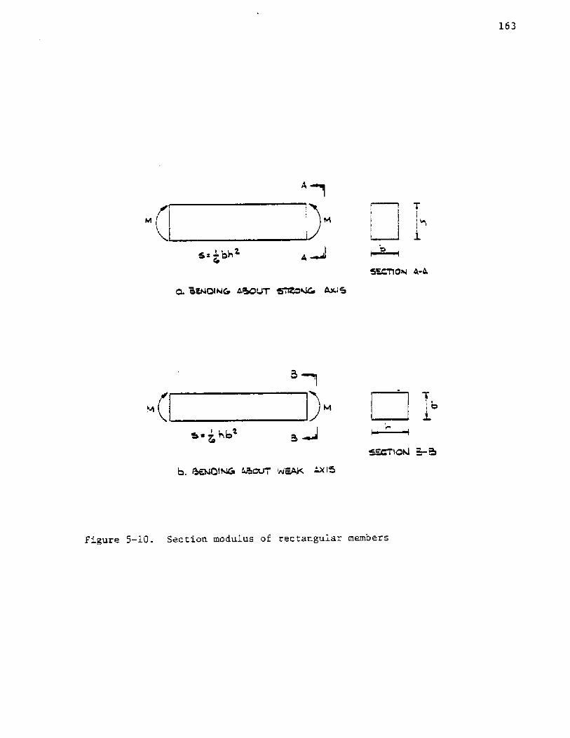
Since most of the timber components are rectangular, the dimensions
may be selected using the relationship
�-loa!S � bh. or
1 26
�-lob!S ~ � b h1 2
6
depending upon the direction of the bending. Equation 5-10a is used forbending about the major axis, and Equation 5-10b is used with respect
to the minor axis, as shown in Figure 5-10.
The section moduli for structural steel members can be found in
Table 5-2 for sheet pile sections and Table 5-3 for channel sections.
Member dimensions are determined from section moduli which are, in
turn, directly proportional to the bending moment, M, and inversely
proportional to the allowable bending stress, fb. Hence, the cost of
the member is related to its strength in terms of its allowable stress.
Table 5-4a contains a partial list of allowable stresses for
southern pine, the wood type most commonly used in Ãew York. A more ex-
haustive list may be found in Timber Desi and Construction Manual by
the Timber Engineering Co. Columns 3 through 7 of Table 5-4a indicate
the allowable: Bending stress f!, tensile stress t!, shear stress
H!, compressive stress perpendicular to the grain cr ! and parallel
to the grain c!, and the elastic modulus E!. The shear stress is
given by
163
5s -'hh~4
g, QIKt4QIhlQ 4lhOUT
I.~<m~aW ~4
I . ~tm WovT
Figure S-10. Section modulus of rectangular members

164
Tab].e 5-2. Engineering properties af steeL sheet piling United StatesSteel, 1979, facing p. 1!

165
jCg Iiii SRI
ltl c*,:cva«i 40 0
' ~ cR R %3 3 %38 RRo I RI 453
K 8 8 3 IS r III o 5 0 Jl «I 3 IS 3» 95@ "9= =5 $1oea oea oe es oaesoa Oas ~ Oas OaO saa
RIR PI 55-::- %%9 %SR 8% 5% R:5
="85 9%8 5" -iR R=Roee Oaci ao se
'4l 'ae
I
os 0I gpss 4 g$3 SRRR SSR
'C ras Nvi vc vcr
Vl IVI
IV ClAvt» vrr
3 NNAA A ANN»Nvv aa»3 N ASNtv»ANN Nlv
Ra RR3tv«i»» r aa A '3 SSR 88CI e Itl 1 Al«C O«CIV IV IV
c «a» I vaNor
Aas
.:3, I 515ooo a cia so a a
$31 XN $3 $ 'gg9 IR 5 R'3 ~ 9%%I IV5$
NNNtv A Nlv I«NN NNN Nlv
N «XXX
A tcA A
XXXC! Itv RXXX
Sl 0 RXXXXO
383XXXIJ
V vlP ItlXXX XX XXXX XXXX
hiI
CI j- ulIll
UJ ICI
oc
bo
gyNX C
a cn
UJa
aoAre«I ltlstv »IA AI NSlv C5 CQI 3 SRRSQQ SAR go'lg I a I » t IVAI 4 001
essa 004 100 444 014 14 10 400
~!-,� ,.gl SSR 2 PILI ~33 BS 35 %35 Ã3IIICI! 92 I 0t«e 1av«1010 444 444 114 044 10 00 140
aae 400 sass Oea 000 eoo aaO ae,ea aee
c I AIRR SR@ CSlllI A>8 eQ
I acr�«l Na a eeaa ACC 1
Vtr«I a«I ccN IV»t«aa a 0 Oe Oe Oe
I ~ g~ ~ I Ravt VlII!II SSQ O'IQR RRRR RR RRR
aae 1 vc rvtva r Iv 33 «3 ASS3 Ot «'IA NIVIV V
l c,lN NR »4 CKRR N 3 3 9»3 za 3» ccROOO NNci ' 'aa aao cicve aer Alia aci 'a
RI ~Rg Rg 3 P'g SSLQ g CS 43 IPR>4« ,, oaa aaa aoae aaa aoa aoa aoa oa oe oao
I Bm %%4%%% RSsac oso ass ciao as cia aao
S88 838 88S8 S88 338 888 338 88 88 338v vt»» Ntvtv Aaoo cia«i aao vioo4
AS 443 «RS» R«$ »5% 83 383 53 -3 RANIA A vl A vl N ~ I N V ff

Table S-4a. Allowable stresses for southern pine Timber EngineeringCo., 1956, p. 483! Allawablc unic stresses, psi l,760,0001,760,0001,760,000l,760,0001,760,0001,760,000l,760,0001,760,000
1e76oi0001,760,0001,760,0001,760,0001,760,0001,760,0001,760,0001,760,000
1,760,0001,760,0001,760,0001,76O,Ooo1,760,0001,760,0001,760,0001,760,000
1,760,0001,760,0001,760,0001,760,0001,760,000'L,760,0001,760,0001,760,000
1,760,0001,760,0001.760,0001,76o,ooolv760iooo
1,760,0001,760,0001,760,0001,760,0001,760,000

167
3V
2 bh
�-11!
in which V ~ the total shear force.
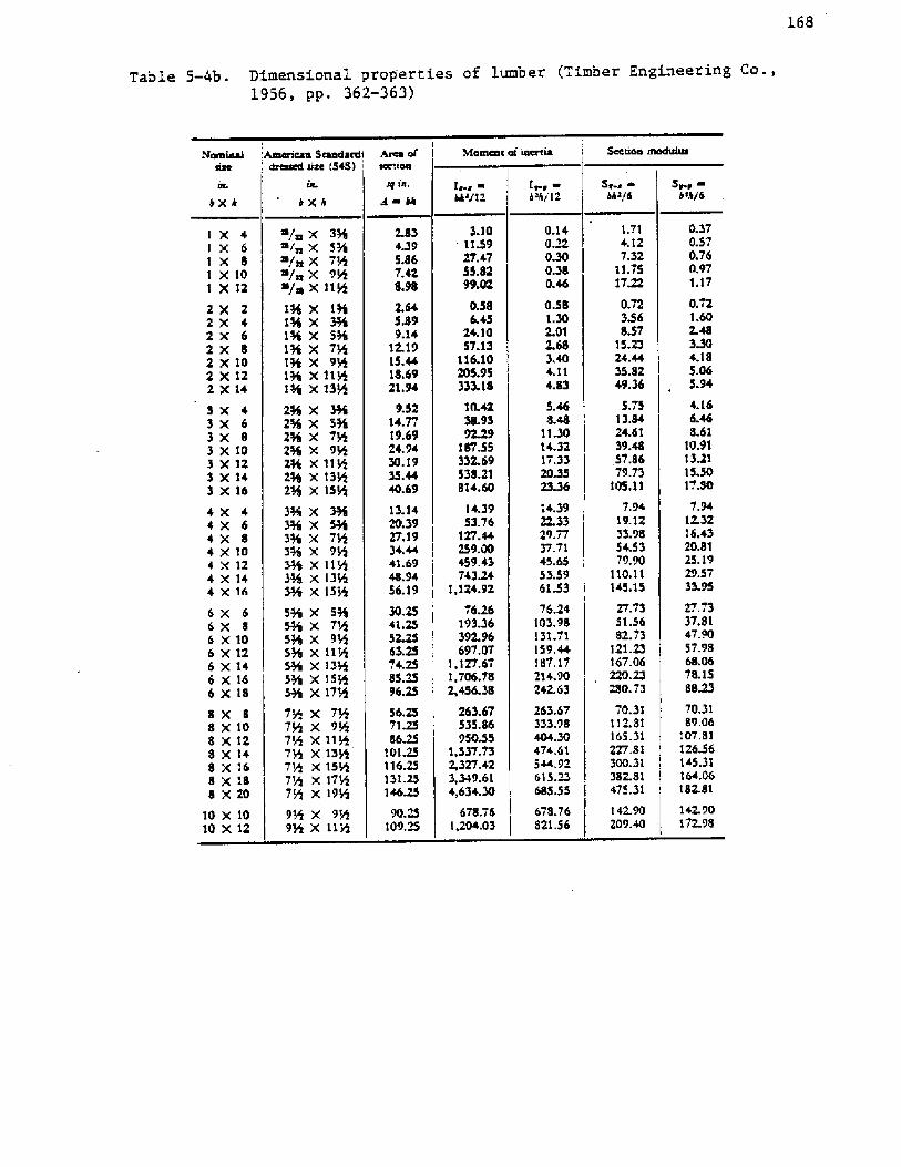
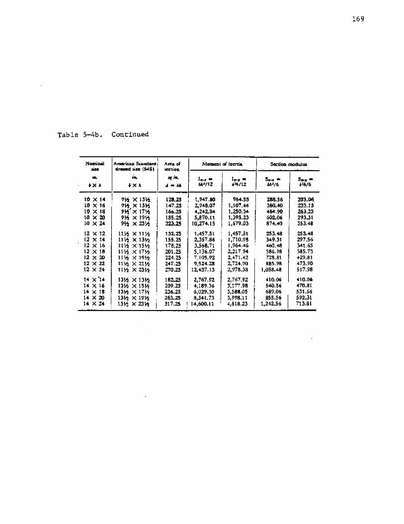
Table 5-4b contains dimensions and properties for lumber.
The allowable bending stress in steel members is a function of
its minimum yield point,, f . For steel sheet piles, ASTM A328, A572,
and A690 United States Steel, 1975!,
�-12a!fb 0.65 f
�-12b!fb 0.60 f
the allowable tensile stress, f , is evaluated the same as for bendingt
stress, i,e.,
0.60 ft y'�-12c!
and the allowable shear stress may be taken as AISC, 1973!
f ~ 0.40 fV y
�-12d!
Table 5-5 reflects the minimum yield point for various ASTM steel
specifications.
5.2.4. Fasteners
Timber components may be fastened by nails or common boles. High
strength bolts AST4f A325! are used for steel.
For A36 steel, which is commonly used for channels, tie-rods, and plates,
AISC, 1973!,
168
Table 5-4b. Dimensional prop'erties of lumber Timber Engineering Co.,1956, pp. 362-363!
Moomoc of iocrrio'AolcncÃo BtotKtocdi ArcE of. '4ro«ed ohio �4$! i
Sr.g ~khan/6 b<hi6
1.714.127.32
11.751722
0.723368.57
15.2324.4435.8249.36
3.10113927.4755.$299.02
1 X 41X 6IX 8I xloI X12
QM0.380.46
0.581.302.01
3.404.114.83
0286.45
24.105'7.13
116.102os.9S333.18
ZX 22X 42 X 62X 82 x IO2 XI22X14
5.7513.$424.6139.4857,$679.73
IOS. I I
5.468.48
I jdo14.3217.3320.3523.36
10.4238.939@29
187.SS33? 69538.21814.60
3 X 43 X 63x a3XIO3X123x143X16
7.9419.1233.9854.5379.90
110.11145.15
27.7351.5682.73
121.23167.06
14.3922.3329.7737.7145.6553.596133
4 X 44 X 64X 84XIo4XIZ4X144X16
76.24103.98131.71159.44187.17214.90242.63
263.67333.98404.30474.61544. 92615.M~6$5.55
678.76821.56
dx 66x 86XIO6X126X146X166x18 280. 73
70.31112.81165.31227,$1300.31382.81475.31
Bx 88 x lo8X128 X 148X168 XIB8XZO
142.90172.98
142.90? 09.40
IOX IO10 X 12
«/X34«/«X 54«/«X 7R
x«/«X 115
IQ XIQ X R4I34 X 5%I3% X 7R156 X 9Q196 X 1116IR X ISA
25% X 3%Zj6 x 5%zs x 7WZj6 X216 X 1j5Zj6 X 13524 X ISN
34 X 396mx 5434 X 7434 X 9534 X IIH34 X 13'.34 X 155
54 X 5%RC x 7RSj6 x 9W54 X IINH4 X 13854 X 15165% X I7A
7N x 7'7' X7~ X 1187Q X 13+7>g X 15+7N X I7'47N xj95
9N X 9A9N X IIR
14.3953.76
127.44259,00459.43743Z4
'1,124.92
76.26193.36392.96697,07
1,127,671,706.782,456.38
263.67535.$695085
I,S37.732,327,423,349.614,634.30
678,761,204.03
0.370.57G.760,971.17
0.721.602.483.304.185.G65.94
4.166.468.61
10.91132115.50I7.$0
7,9412.3216.4320.8125.1929.5733.9S
27.7337.8147. 9057,9$
78.15$823
70.3189.06
107. $1126.56145.31164,06182.81
169
Table 5-4b. Cont:inued,
Ih tlctreeo Ssersdersl [ ~ efdressed slee �48!
bfemces al issue
IX' 6sh/L2S~e ~hsk/6
S~ ~Lks/66XA
12,437. 13
10 X1410 X 1610 X 1810 X 2010 X24
12 X 1212 X 1412 X 1612 X 1812 X 2012 X 22t2 X 24
14 X t414 X 1614 X 1814 X 2014 X24
9rrS X 1349rrS X ISN95 X LT+98 X t9H95 X 23'
tt+ Xtt+tlat X L3<tt5 X LS~LIN X LTHlip X L9~+It Les X 21LS115 X 234
13+ X13gL3+ X IS+13+ X LT+t3+ X L9+gI3te X 234
182.25209.&s236.2S263.25317.25
2,767.924,189.366,029.308,34t.73
14,600.11
964.SS1,107.441,250.341,393.231,679.03
1,457,51'1,710.981,964.462,217.942,471.422,724.902,978.38
2,767.923,177,983,588.053,998.114,818,23
288.56380.40484.90602.06874. 40
253.48349.31460,48586.98T28.81885.98
1,058.48
410.06S40.56689,06B55.56
1,24~6
203.06233.15263.2329341353.48
253.48297.56341. 65385.73429.8 L473.90517.98
410.06470.81531.5659221713.81

170
A328
A592 Gr 50
A640
Table 5-5. Mninum yield point
Steel Brand or Grade
38,500 psi �65 NN/m2!
50,000 psi �44 MN/~2!
50,000 psi �44 NN/ra !
36,000 psi �48 NN/m !2

171
�-13!W pg,r e
The allowable Lateral loads on nails should be checked. Nails
fastening southern pine and douglas fir are allowed a maximum shear
of
V ~ 1650 D
in which V the allowable shear in pounds and D is the nail diameter
in inches Timber Engineering Co., 1956!.
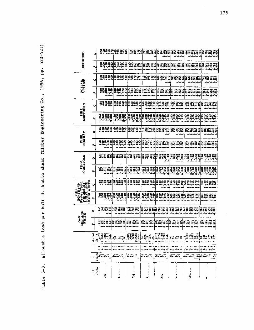
Common bolts mav be used in wood splices and their allowable
loads may be found in Table 5-8. Allowable loads are for bolts in
double shear, i.e., bolts used in 3 member joints, as in splice plates
for wales Figure 5-lla!, The controlling factors in Figures 5-10 and
5-11 are the bolt diameter, d, the length of bolt in the main member,
b, and the relative size of the splice members and the main. member. The
The capacity of a nail as a fastener is determined by its resistance
to withdrawal, W , which is in turn a function of the effective lengthr
of embedment, II, , allowable load in withdrawal per inch of embedment,e'
p, and specific gravity, G. The effective length of a nail fastening
a sheet pile to a wale is the length of embedment in the wale, i.e.
the nail length minus the thickness of the sheet pile.
To find the allowable load in withdrawal of a particular nail
size, the specific gravity, G , of the wood is first found by usings
Table 5-6, then entering Table 5-7 for the desired nail size and specific
gravity. The resistance to withdrawal is given by

172
Table 5-6. Specific graviry of wood members Timber Engineering Co.,1956, p. 553!
Sbeelgar!rsutgr
tC!!SoretdeGreeter
C!!
!gaehb¹rr!tcaaoch. CaeCCL!Ctecorg
ONNL ~ ~
Alder. rsLAsh. OtsAeh. Oreeaa..AC4 IrhtN
Sseocod.Seers.S tres. OeeerSINO. Saoee..SN, 3¹rs+ ~ ~
Io¹¹C. btceg ....Lo¹¹4 hoser54 CONae ~ktsgoet� eueale ber.Cgsga¹� esccgreca.
Sueser4 re!toeSure«oae.../assr. Al sabaader, clSC4 Ng
Ceeer. Ioccasa.
MMCCI4 bbrMelee heal Mesc!btael4 acre INC! ...!CCO� CCCC fsgeer!cg, co¹slNtst Nd ~
4Nuaccctst OOICLFossa. ~Crt a4 toggco¹cPIO4 horthors ohtta
Ceder, oorchsro ah!CL w ~Cesar. Pete Oltetg......Cager. Csaehsra o alta,Cease, ONCcra NOCherrr.. bteeg ~Cheater IC ~CCIIOOCCIE laces ~COCCOOIWL ssse¹o ~ * ~Ct 0NE coothca!hruglse 4r. Casse !tcgtea...----------
pta4 !toner.Pl oa, pooderoEPta 4 aluta¹ll ~ICO4 rouchela iaeaoaLPIO4
Douglaa or. Irosse !tee!ca. deNO.......Douglas Or. deoaa,.......... ".-"-ZLE AarerhsoEIE roshXII4 eo Ogerr.
catha relate ab!CLtataer. l eaalt edoood......SOCOC4 kag¹rhaaa.........8arusa Na ~Sercc4 ¹thsSetoe4 Calla.Sugar hsrrr.Bres¹or4Terasrssg
. hetaera ..Ftt.!tt. Cruaas¹atsi Irhlte..QOE bl~OCE red...t!CE tue¹ra co¹oa4 b lech
erhh¹e. !csea
0. CS
,di. il
.Or:Fr'
.Cd
.!r,i3. ig.5!. 51
.C4. 5!'
.Ct, i2
0. 54, ii
.T!
.41
.de
.52
.Ct
.!I
.I3
.Cr, i2
,ig.C3
.Cl

173
~ C MMQ aoSCSoCe g O~ «OOt RQ NRS
P PIoooVgacc «lg c«a gIPCAv volvo
OCC 4NVVPl Pl CI««92el
o Cl aNV V
MIooav I4t I IgNV P g
w te $IlQN IVC«Ã
ofto pl at e ~CQNV
Mag4VQ %CO«I aa
5MC92 cpp4 0 4«IP ONSVPl I«CI ~Vat
CC $1 3 CI gMs aÃSNaa Cev 'a I
Ca «l caMalag VVIMVS vZSvaot gM ooo
g ON 4 O«ewwaM «I
cea
Q cc arCt «I cgae Cl NCe QCC
Ma W VI
ovt o«e «I g«l M ael«i peV Me~ 92 C«CI
cg o ce SoaC«VINCMNVg
vov'4 RQMM4 atNPC V
el a gRM A PIVMIV 4«lICl
C92 MI'4 4Vclca v 'CI Ie» gNANN ce ceI aavvaN Cl
«IC4 QAN@ RNM «ec oM M PlVOI agOo Pa«e V
do VN pcog N P«lpc Cp ca4 «lea Ceaao
«I
PC g VeeI
ORv
4-04$444o a~oTl o8
~O
RSQ CSC NQC ROC
CSQ 38M WQC SQS
t QQ ggN VIOL
va"v8 'Q«IN ala

N ~
' ~NNa%a Cgg t OCNN
-aQ
aaa ggN
Qa gga
I
I
O ct ggaN fJ
C 0O
à I
RCQ a
a~g Nag
greg Nag
gXR Saba
RSR Caa
~Ra aa4
j75
RRROS aoaooloooSRODOOOD Crt CC ~Pl % r ca caOOOSo220-L'
Qaoo8CI8 Car SRRSRSclearer 4
800000a ta realrcr ecol ODC DD Cr-crCao
oa l oo o:-RRB SaooyR!OOOOSODRS44F OF! SDDS~ Carceca r aaCc CC Pl C4 Fr r ca
QODDR'0QOmrC
OOOO OBOD-4
eel CC
0 8RDDOca 04
008000
&w& & CC ~ ci rc aa rCCFCIC r
Qo!DRgoogSCa ca a D D I SROFCCCro IS 80 ca r Ca rggggo QRIS tria!OOQ
4 4 4caca
00808 OOOQOrrcacaa
OSQODO0 OOOODS~DD RRRRDDOc oa tc
SDRDQD~ S 4CCPl '4
Dao@0i DODFaccrrca
RDDDSt 0 PicaiSRDDR$ 8 R $~00!8 R RRJRooogo ooaoono ca vacaPI carOorair accords
CC Ci Ci Ci Fi 4 44 Ca Fa w ca lc aa w ca F! Ca r
RoaaalRISooiaIRoRoDDQDS~ c tc r r ca
OSOOoDca rcaB
0 ooooar0 Oc ceo r 4440 c aa circ 0 catcIC
aooooloooooa Ir r oarpalr rDODOSCa cr Cl Fr
OOOOO OOOO 0r aa 44 t I4 0 R C4 4DOPV r cr 00 04~00000care.l00 40
Dao oar I a CI IClr Oc40 cr 44 4 rccc ca tc
OOOOOIOOOOSIr creat 444accD 4 0 CC j ca C ~ ca ~
aoOROOc cCOS
CI 0 0 0 0Facet tetPa F'r ca aco0o08r aatcDPi 8RRSR8alccrat 4
0 o 8 CI 0Dear ceca
SOOOOOt Fr4 rc rear
co oc 0 iac oa a ice oooo444 Cccc 4 ac Col+ac ICC+C4Fr e Fr ca pic ta ca I Io 4 Ie ccCc Ci ca CC Cl CC r4 44 rc CC
DDDRO a4 a ca a CC Pr
OOODO44 0 44 v vl ICOOccgS4r ~ 4IRSRS40 ca+a
.2;IQ
RZRR SSRRR SRS~SI$~8~ -RcCIP aa ic4clC r Pleio It, 'F I ~ ~ cca'4 0 IC44 ca ca ~ ' ci Fir cata r ~
I . Q a Ia C4 Ic I g Catt&44 .cic t I.Cl r cr I 4 t P 0I
.-.CCDOFC lamC pCICDO-e Iap~aalo CIO-~cjaar-c-Crtoc-.. ~= .�.p.!t.tier.-.~x=ci . i=r =~rrja'laic Cop
oclr c.a.l' Icla
eve m+c
a 8
R8ci-If-+ Cf 8
oSoaalO ca w 8 Cl
oooo o lao oo0cg Ia atr r ca 4 44 4 0 t IN
SSDDoI ra i r Ccc c'I
CC CC Ca C4 Fl
SZQRIcapt r
0000!CCCCD
So�8ca D 0 aa r
CacC r
0DDROaotaarInaca ca ttl
ROOOODra mOOFIC4044Caca r r
Oooo ooI 44449 0 r ca 4 e4 4 Ci IC tc r
0 Dace 0cate 4 w 4cio 4 voC4 ta Fa &
OOCOOOQl or caI Iccct 4C4 Pl ~ ICI


177
o>ep
b. '2 >R,w&~ alNT
Figure 5-11. Common bolts as fasteners

178
tabulated loads are for members where side members are at least 1/2 thedimension of the main membex. Where side members are thinner than 1/2the main member, then, for the purpose of determining xhe allowableload, b 2a. For example, if a wale is 6 in �52 mm!, then the bdimension used for Table 5-8 would be 3 in �6. 2 mm! .
The values in Table 5-8 are represented by P for loads parallelto the grain and by Q for loads perpendicular to the grain. For thepurpose of wale splices, the allowable load in shear per bolt, V, canbe taken as Q in Table 5-8.
For 2 member joints Figure 5-lib! of equal thickness, the allow-
able load is 1/2 the tabulated value for a main member whose thicknessis twice that of the actual member. For example, for a 2 in �0.8 mm!member in southern pine, enter Table 5-8 at 4 in �01.6 mm! for theappropx'iate bolt diameter. The allowable load, Q, for a 1 in �5.4 mm!bolt is 4720 pounds �1.0 kN! and the allowable load in shear per
bolt, V, is 2360 pounds �0.5 kN!.
For 2 member joints of unequal thickness, the procedure outlined
in the previous paragraph is applied with respect to the thinner
member.
Whex'e steel plates are used as splice members, the allowable
load is incx'eased by 25 percent.
The criteria for allowable loads in common bolts axe summarized
in Table 5-9.
The allowable loads on high strength bolts AS' A325! are
40,000 psi �76 M/m ! in tension, f , and 15,000 psi �03 M/m. ! in2 2
shear, f A.ISC, 1973!,v

179
Table 5-9. Summary of allowable loads in common bolts used forsplice plates
Joint T e
3 Member b ~b
b~2a
b~2a2 Member a~b
b-Zaa<b
b 2ba>b
n/a b b 1. 25PSteel Side Plate
Relative
Dimensions
Enter Table 5-8,Column b at
Allowable
Load V
180
n, is
Pwn
Wr
�-15!
in which P the tie-rod pull force per unit length of wall!, w
the width of the pile section, and W the resistance to withdrawalr
per nai,l. The ~umber of high strength bolts per steel sheet pile,
n~ is
4Pw
~d f2
t
in which d the bolt diameter and f the allowable tensile stresst
per bolt, taken as 40,000 psi �75 NN/m ! for A325 bolts. The allow-
able shear stress, f , in A325 bolts is 15,000 psi �03 NN/m !2
V
The cost of fasteners is dependent upon their required size and
number which are, in turn, determined by their capacity and loads.
Another determinant to be considered is the location of the wale, i.e.,
whether it is located on the fill side or the dredge side of the wall.
Locating the wale on the fill side presents a smooth face for the
user, whereas locating the wale on the dredge side presents a protru-
sion which may interfere with mooring. However, with the wale located
inside the fill, more fasteners are required as the fill tends to push
the sheet piles away from the wale, exerting a prying force
Figure 5-12a!. On the other hand, a wale outside the fill bears
against the sheet piles, thereby eliminating the consideration of
prying forces. The number of nails required per wood pile section,
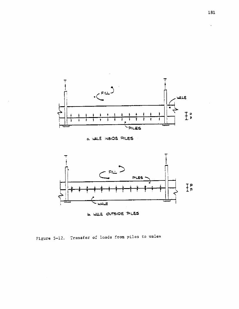
Figure 5-12. Transfer of loads from piles to wales
182
Holes are 1/32 in �.79 mm! larger than the bolt diameter for
wood and 1/6 in �.6 mm! for steel.
5.2.5. Bulkhead Lifetime
The life expectancy of a bulkhead depends upon the components of
the system, i.e., if one component fails, the system is no longer
viable. Obviously, the lifetimes of components vary from material to
material, and the material with the shortest lifetime will control the
bulkhead lifetime. The designer must, therefore. insure that the
material of each component is the optimum.
The structure must be protected from harmful agents that exist in
the environment. Timber must be protected from rot and other
biological agents by an appropriate treatment as recommended by the
American Wood Preservation Tnstitute AWPI! and the American Wood
Preservative Association, AWPA!.
Timber sheet piles usually consist of heartwood instead of sap-
wood. This may cause the purchaser some consternation as standards
established for preservative penetration are for sapwood, not heartwood.
Since heartwood is more resistant to preservative penetration, it follows
that the preservative penetration of many sheet piles will be less than
optimum.
Steel sheet pile and tie-rod life can be prolonged by applying
special coatings. Corrosion and decay rates should be determined for a
particular environment so that the Life of the structure can be esti-
mated. A, detailed discussion of materials and the hazards present in
certain environments is contained in "Coastal Structure Nateria1.s"
Hubbell and Kulhawy, 1979!.
183
Tie-rods, turnbuckles, bolts, nuts, washers, and nails receive
protection from corrosion by galvanizing. Electro-deposited zinc
coatings, in accordance with ASTN B633, or hot-dip coatings, in accord-
ance with ASTM A513, may be specified to increase the life of steel
components.
When the cost is favorable, hardware may be comprised of wrought
iron.
If no coating or treatment is speci, fied for the hardware, the
required dimensions will be reduced by corrosion. If the amount of
deterioration is known, the dimensions of the hardware should be in-
creased by this amount eo preclude failure. Recommended increases in
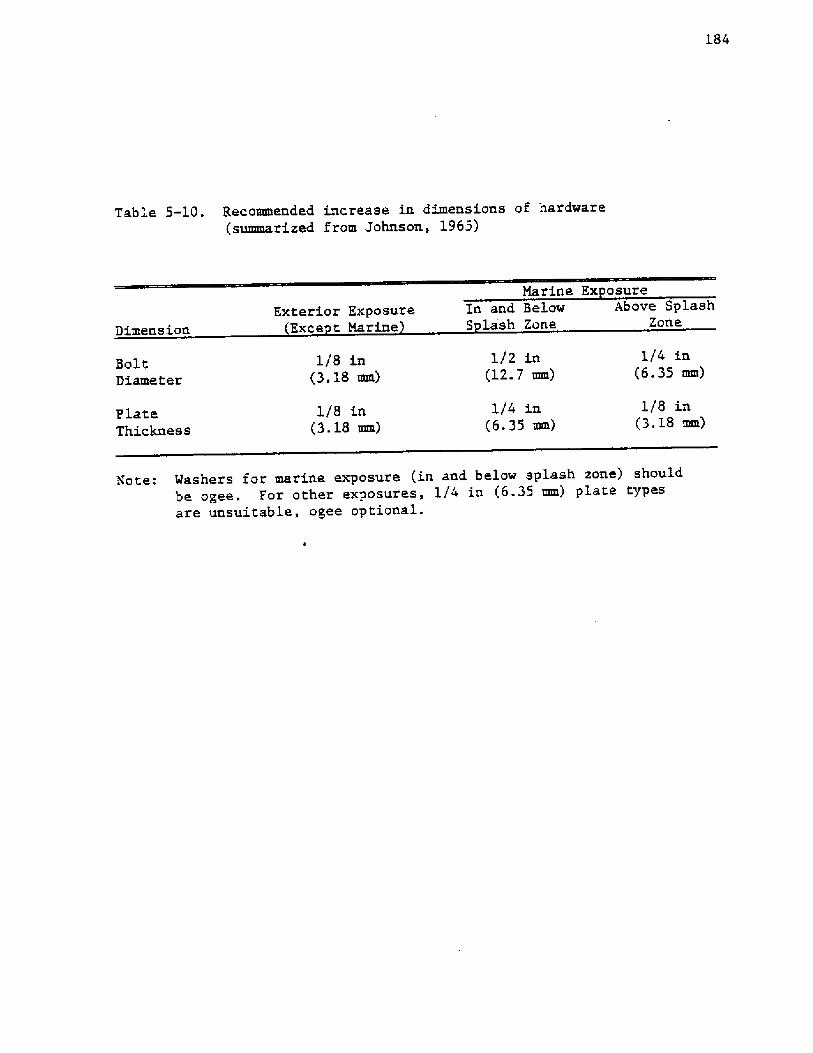
hardware dimensions are shown in Table 5-10 Johnson, 1965!.
Bulkheads sited in erosion zones should incorporate returns on
the flanks of the bulkhead see Chapter 6, Figure 6-1! . These are sec-
tions constructed perpendicular to the wall which prevent the washout
of backfill around the flanks.
5.2.6. Cora liance with Indust Standards
The designer may enhance the quality assurance of the product by
making certain that suppliers comply with industry standards, such as
ASSN and AWPA specifications. This may be accomplished by inspecting
timber products for grademarks Figure 5-13! and by requesting certifi-
cates of compliance from the supplier. Such requests are reasonable
and the documents certify that the provisions of the specifications
are met.
184
Table 5-10. Recommended increase in dimensions of hardware summarized from Johnson, 1965!
Marine Ex osure
Dimension
'Aote: Mashers for marine exposure in and below splash zone! shouldbe ogee. For other exposures, 1/4 in �.35 mm! plate typesare unsuitable, agee optional.
Bolt
Diameter
Plate
Thickness
Exterior ExposureExce t Marine
1/8 in�.18 mm!
1/8 in�.18 mm!
In and BelowS lash Zone
1/2 in�2.7 mm!
1/4 in�.35 mm!
Above SplashZone
1/4 in�.35 mm!
1/8 in�.18 mm!

186
5.3. Desi of Com onen.ts
5 3.1. Sheet Piles
When the maximum moment has been determined Chapters 2 and 4!,
the required section modulus is found by employing Equation 5-9. Since
the moment is computed in terms of moment per unit length of wall, the
section modulus must also be in terms of unit length per wall. For
steel sheet piles, Table 5-2 is consulted, as is demonstrated in design
examples found in the Appendices.
For rectangular wood piles, the required thickness is found by
employing Equation 5-10a, as is also demonstrated in design examples.
No load factors are required for sheet pile calculations. A
material factor is already employed in the allowable bending stress,
fb, for steel and wood.
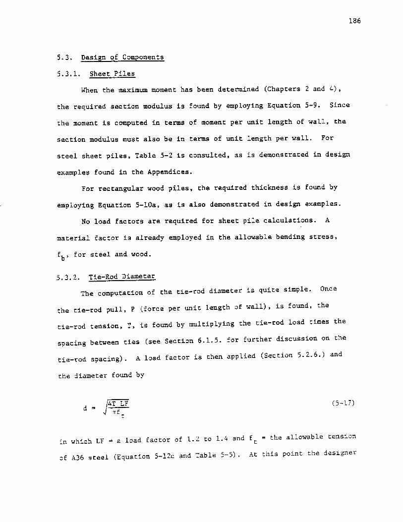
5.3.2. Tie-Rod Diameter
The computation of the tie-rod diameter is quite simple. Once
the tie-rod pull, P force per unit length of wall!, is found, thetie-rod tension, T, is found by multiplying the tie-rod load times the
spacing between ties see Section 6.1.5. for further discussion on thetie-rod spacing! . A load factor is then applied Section 5. 2. 6.! and
the diameter found by
4T E,F
t
�-17!
in which LF = a load factor of 1. 2 to 1.4 and f = the allowable tensiont
of A36 steel Equation 5-12c and Table 5 � 5! . At this point the designer
187
may decide to increase the diameter of the tie-rod for corrosion if no
other precautions were taken Section 5. 2.5.! .
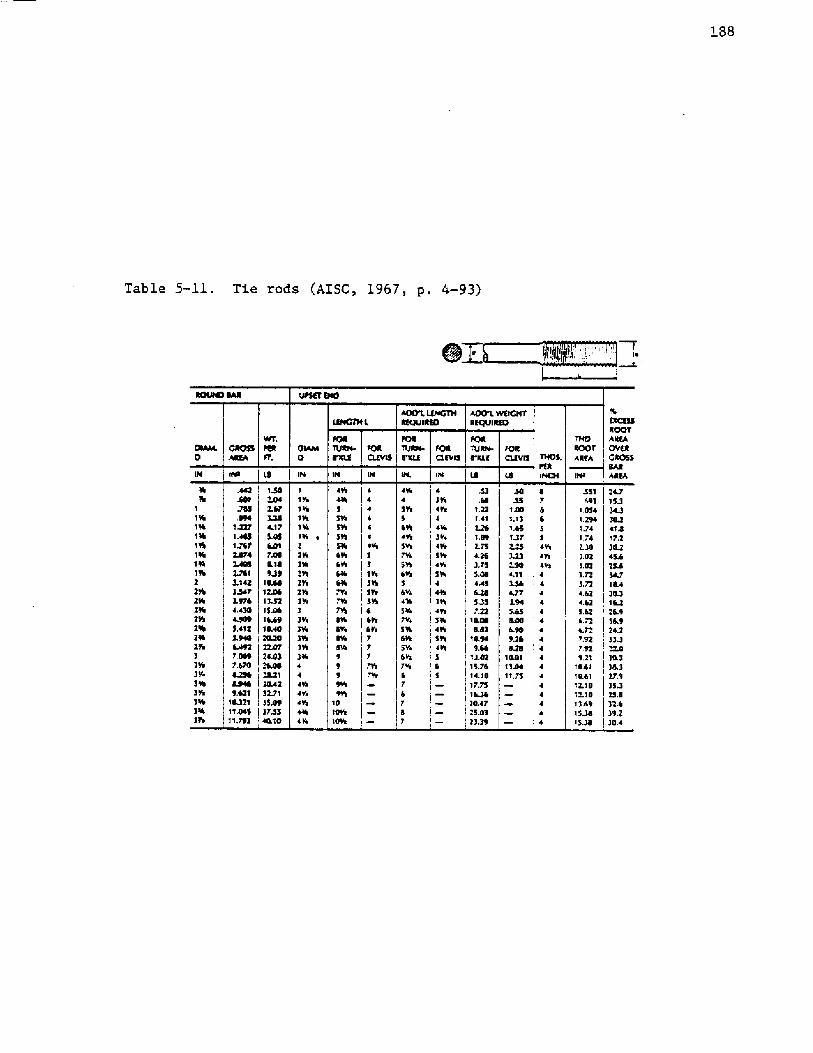
Tables 5-11 and 5-12 contain data for tie-rods and turnbuckles,
respectively.
An example of determining the tie-rod diameter is given in the
Appendices.
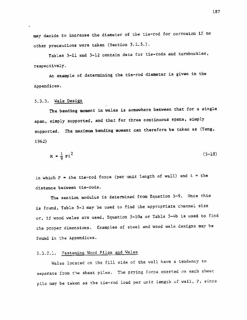
5.3.3.
1962!
� pi1 2
9�-18!
in which P ~ the tie-rod force per unit length of wall.! and R = the
distance between tie-rods.
The section modulus is determined from Equation 5-9. Once this
is found, Table 5-3 mav be used. to find the appropriate channel size
or, if wood wales are used, Equation 5-10a or Table 5-4b is used to find
the proper dimensions. Examples of steel and wood wale designs may be
found in the Appendices.
5.3.2.1. Fastenin Wood Piles and Wales
Wales located on the fill side of the wall have a tendency to
separate from the sheet piles. The prying force exerted on each sheet
pile may be taken as the tie-rod load per unit length of wall, P, since
The bending moment in wales is somewhere between that for a single
span, simply supported, and that for three continuous spans, simply
supported. The maximum bending moment can therefore be taken as Teng,
188
Table 5-11. Tie rods AISC, 1967, p. 4-93!
I ~
t!tCKSSROOTAltKAOVRRGROSS
At 74 VV8GNTREQVI 8813
TH�ROOT*RTA
FORa.RVIS
/ORCLEVIS
INt 38 IN84
351 !*7693 15J
1.054 �J1.294174 O'IJI J4 17J430 !OJ!.OZ 45k483472 342! JZ I RA4.62 ! 30.3
1 1 961 tl1961 96
!t6!96
2 Zth316
291296
216
3 3743%394399
346396
A42
.785
1 J271.488t J8748744485478t5,'1423 J4749764 A 304589SA125.9486AOZ
7470RJ90RO469,629
18J2111 4�511,793
I JOI2.67!JO~ .�5.05
8.189JO
10801 2.881!.52153�1 6A9
!
1 %40
3144Z! 347!! 339! �JS
1t 161161tlt 16t tt ~3
3�
3�
3tti
!TE316444194'4944414 It
4164ll5516SVSStt5966tl619616616716
7944164 VI~ 16
9 ~ Vl18189919th
4
4 4 ~ VlStdS 5195
6 6Vt
7 7 7 ~ Irr
436
4 5th5 ~ 194 IHgSV9795St!
56V4145167%51661959i6Va7166 7
6 7 4 7
4 !V44tg
!Vi4Vt
4'5 tti
416
4thSll41%593
5 6 5
JZ.68
1.321A12261.89475*263.75$.0114A5
5JS7.22
10,088,82
'10,949.66
13.8215.761 ' .1817.75'l~!OA725.8333 Jt
30JS
1 38!4131.651J7
4234904,1'I456~ JT3.945.65LRO6.90'9.26428
10.81t!M
4 7 6 5 5 495~ 4V14 44 4
4 4 4 44 4 44
4.625.6Z ' 26.96.72 49
, 2*2492 , '�!795'9.21 ! 38J
18.61 ! !RJI 861 37.912.'18 35J12.18 I 35.41469 I �61SJR ! 39.3ISJR ! �.4

1S9
Table, 5-12. Turnbuckles AZSC, 1980, p. 4-143!
WEIOIT Of TUOIIOUC5255, FOUI405
I.EIICTSI, A. 04E34eSTAIIEIAOEI TUota043CIILES
ISIA44O 0164EHOIOF15, ltsCSIES TUaaOUC064
SAFE WO IMMY3612 1414
694dXs
1.001.502.'T3
1.34T.sj
Z.433.06*20
4.255.43
10.04 40 ta056 10
3 so4. 704.70
6
6 jI
s.13 15.30 13 1
9.1S ! 1650I ~1'9A
1600 I tXSO15.25
372
60.075.0
27804150433054.00
1525TSM3%60
11501 LOOZSM3140
2"As33Va
1th1ZIS1 Std149a
3Vs3464Vs
445aa5Salt
2 6
ZVa I 6 I
9LJI ZZZTXLZT62.0
4Vs5VsSVs6
15169116Va10
356394
~ Vs
3563VT
5 Vs3 Va3Va
SVa
946946
44 'ls4Va4Va
10
1 1VaItsI IS1VaTVsTasTVs
Xs
'9!oTXs1 954
IIaaTXF546
2VaZVa256
00a
91st99a
TOVaT0Va111't Va
'to2ZVanTS
24
XsaX4%aaXa
TSSt
1XsI'4taatXs
T aVaat aVaa294
TXsIXs19aI aXsTXa
ZVaaZXs2'Xa
jlsa35543Xs
.45
.75t 001A5'f.05
ZAOXZ23.504.50350t50950
1150
152.01 52.0TSZ,O250.0
TQK23,5LZTg
98TTATED17.4ZT.O265
32M
167%233>
233%294.1

190
Pn ~�W r
�-19!
An example may be found in the Appendices.
Wales located on the dredge side of the bulkhead require nails
for construction only. Using two nails per sheet pile should be suffi-
cient. The nails should, however, be long enough to have adequate
embedment in the wale so as to be capable of transmitting shear, i.e.,
2/5 of their length Timber Engineering Co., 1956! or
2/5 2,.e
�-ZOa!
Since the effective length, I, is the length, i, minus the pile thick-
ness, t, the nail length should be
Z 5/3 t. �-zob!
An example may be found in the Appendices.
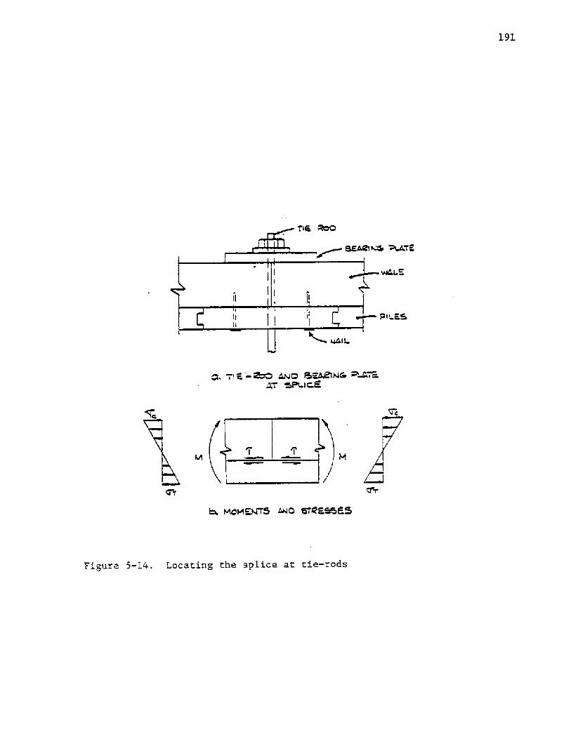
S. 3. 3. 2. S lices in Wood Wales
Advantages are gained by locating the splices of outside wales
at the tie-rods Figure 5-14! . The bending moments here cause compres-
sion of the outside edge of the wale and tension at the inside edge.
each sheet pile is approximately one foot wide. The number of nails, n,required per pile may be found by selecting a nail size, determiningi.ts allowable load in withdrawal, W , from Tables 5-6 and 5-7 andr'
Equation 5-13, then using the simple relationship
>@ATE
w445
Figure 5-10. Locating the splice at tie-rods
192
TA ~�f p
�-21!
The thickness of the plate is given by AISC, 1973!
3 F N�-22!
in which: F the actual bearing pressure, N = 1/2 the short dimensionP
of the plate minus the hole radius, and f the allowable bendingb
stress of the steel. An example of the bearing plate design for an
outside wale may be found in the Appendices.
The tension is resisted by the sheet pile 'attached to the wale at this.
location Figure 5-14b! .
A splice requiring a 2- or 3-member joint Figure 5-11! may be
eliminated. In addition to cost savings, elimination of the splice re-
moves the potential for ponding that would occur between the horizontal
members of the splices. Ponding hastens the decay of the wood.
An advantage is also gained as the tie-rod hole in the wale occurs
in an area which is penetrated with preservative throughout the entire
length of the hole.
The bearing plate is designed in a manner similar to the design
for bearing of a steel beam on a masonry wall. The plate area is
determined from the allowable bearing pressure, f , taken as c x fromP
Table 5-4. The area, A, is found from

193
Inside wale splices must be 2- or 3-member joints Figure 5-11!.
The average shear force, V, that the bolts must resist may be found
from
1V � T � � PT-
2 4 b�-23!
5.3.3.3. Fasteners and S lices for Steel Wales
Figure 5-15 displays typical details for inside and outside wales
used with steel sheet piles. Inside wales are fastened using high
strength bolts in conjunction with a fixing plate. The number of bolts
is determined by Equation 5-16 and the fixing pla.te may be dimensioned
by approximating it as a simply supported beam with a point load.The minimum distance from the center of the bolt hole to the edge
of the member may be taken as 1.5 times the bolt diameter for rolled or
in which L ~ the distance between extreme bolts. Equation 5-23 is
valid for splices centered over the tie-rod. The splice should also be
designed to resi.st the maximum moment.
Bolts in the splice have minimum requirements for end distance,
edge distance, bolt spacing, and distance between rows of bolts. A
summary of these requirements appears in Table 5-13. These are for
loads acting perpendicular to the grain Timber Engineering Co., 1956!.
The procedure for designing a splice is to select Lb, compute V,
select a bolt size in accordance with Section 5.2.4, determine the
arrangement of bolts, and determine the final length of the splice member.
Examples of 2- and 3-member splice designs may be found in the Appendices.

Number of Bolt Diameters, ndDistance
End
Edge
Bolt Spacing
2 � for 1/d 5 2!1
2
5 for 1/d 5 6!
�/8! �/d! + 1 � for 2 < 1/d < 6!1
4
Rows of Bolts
1/d = bolt length/bolt diameter
Table 5-13. Distance requirements for bolted connections TimberEngineering Co., 1956!.

195
STEEL
PILE WA Tf WASHEIIICVTSl OEWALE
FI XCNO PLATE PLATE WASHEIE
Figure 5-15. Typical wale and anchor details U. S. Steel, 1975, p. 39!

196
gas cut edges. Minimum spacing is three bolt diameters AZSC, 1973!.
An example of the design of an inside wale may be found in the
Appendices.
An outside wale may be fastened by merely employing a plate of
sufficient dimensions between the wale and the tie-rod nut. A plate
washer will suffice if the separators allow the channels to be close
enough to each other.
Splices in wales should be able to transfer the maximum moment
in. the wales Equation 5-18!. The splice plate may be dimensioned
using Equations 5-9, 5-10a, and 5-23. Design of splice plates for
steel channel wales may be found in the Appendices.
5.4.
Once the anchorage is adequately located with respect to the
geometry and soil strength of the site, the type of anchorage must be
chosen and dimensioned.
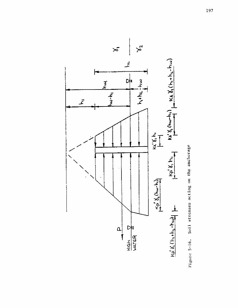
5.4.1. Continuous Deadman
The capacity of a continuous deadman stems from the net resultant
of the soil stresses acting, as shown in Figure 5-16. When considering
these stresses, the distance to the high water mark should. be considered
as this represents the lowest capacity of the deadman. The stress
coefficients K' and K' used are factored, thus requiring no additionalP a
load factors for the design. An example is given in the Append'ces.
197
198
5.4.2. Short Deadman Near the Surface
The calculation for short deadmen near the surface can be facil-
itated using the information obtained from the design of a continuous
deadman. The net capacity per length of anchorage P - P ! isp a
already computed in terms of h , deadman height. The remaining values
are merely substituted into Equation 5.7. The Appendices contain an
example of the design of a short deadman.
5. 5.
Bulkhead design requires the integrated consideration of Loading,
cost-effectiveness, and the design of the basic bulkhead components.
A detailed examination of these considerations has been presented in
this chapter.
The bulkhead may have to withstand loads other than those
stemming from the retained soil. These include surcharges placed on
the backfill, hydrostatic imbalance, ice thrust, mooring loads and
ship impact. The Loads imposed on some components should be increased
by. load factors, depending upon the inheren.t uncertainties.
Cost-effectiveness i,s dependent upon such interrelated factors
as type and configuration of the wall, material strength of the cora-
ponents, ability to withstand harmful agents of the environment, and
fastening methods.
Each structural component must be dimensioned and the type,
number, and spacing of fasteners must be determined. As each item
199
is being selected, the designer must keep in mind alternative materials
and schemes, costs, and the desired function of the component.