Series T6T Tie Rod Construction Hydraulic Cylinders · Series T6T Tie Rod Construction Hydraulic...
13
Transcript of Series T6T Tie Rod Construction Hydraulic Cylinders · Series T6T Tie Rod Construction Hydraulic...
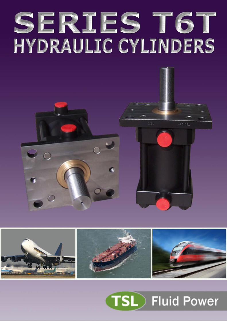
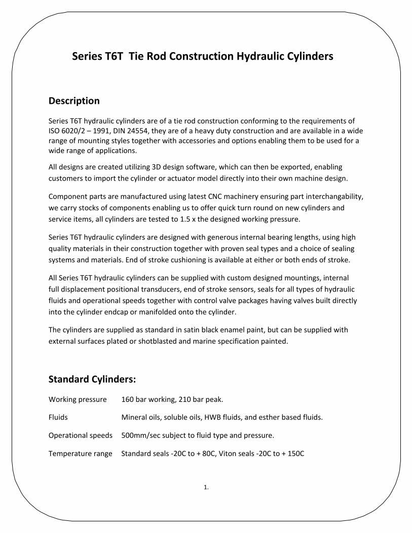
Series T6T Tie Rod Construction Hydraulic Cylinders
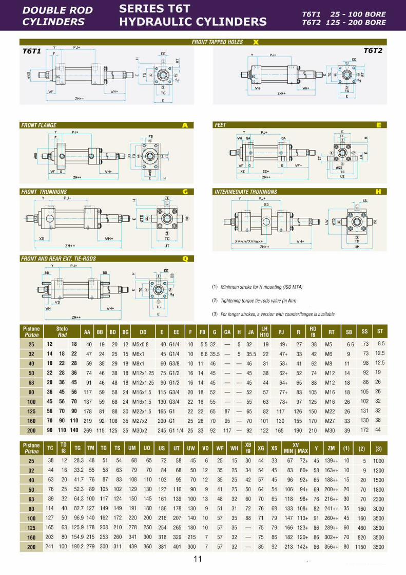
Description Series T6T hydraulic cylinders are of a tie rod construction conforming to the requirements of ISO 6020/2 – 1991, DIN 24554, they are of a heavy duty construction and are available in a wide range of mounting styles together with accessories and options enabling them to be used for a wide range of applications.
All designs are created utilizing 3D design software, which can then be exported, enabling
customers to import the cylinder or actuator model directly into their own machine design.
Component parts are manufactured using latest CNC machinery ensuring part interchangability,
we carry stocks of components enabling us to offer quick turn round on new cylinders and
service items, all cylinders are tested to 1.5 x the designed working pressure.
Series T6T hydraulic cylinders are designed with generous internal bearing lengths, using high
quality materials in their construction together with proven seal types and a choice of sealing
systems and materials. End of stroke cushioning is available at either or both ends of stroke.
All Series T6T hydraulic cylinders can be supplied with custom designed mountings, internal
full displacement positional transducers, end of stroke sensors, seals for all types of hydraulic
fluids and operational speeds together with control valve packages having valves built directly
into the cylinder endcap or manifolded onto the cylinder.
The cylinders are supplied as standard in satin black enamel paint, but can be supplied with
external surfaces plated or shotblasted and marine specification painted.
Standard Cylinders: Working pressure 160 bar working, 210 bar peak.
Fluids Mineral oils, soluble oils, HWB fluids, and esther based fluids.
Operational speeds 500mm/sec subject to fluid type and pressure.
Temperature range Standard seals -20C to + 80C, Viton seals -20C to + 150C
1.

Materials of Construction Tubes:
Up to & including 100 bore – ERW, DOM, grade E355 (ST52). Bore tolerance H9–H11.Surface
finish 0.8 microns Ra max.
100 bore up to and including 200 bore – Cold drawn & honed, grade E355 (ST52).
Bore tolerance ISO H8 –H9.Surface finish 0.3 microns Ra max.
Rods: CK45 (EN8D) carbon steel.
431S29T stainless steel, hardened and tempered, stress relieved.
Micro Cracked hard chrome plated
Standard chrome plate deposit 25 microns Additional plating depths or plating systems available if required.
Gland bearings: Gland bearings are manufactured from a high grade self lubricating bronze and provide
maximum rod support within the cylinder envelope dimensions.
Longer stroke cylinders are fitted with internal stop tubes to increase the overall bearing length.
When stop tubes are fitted, this length is in addition to the base length of the cylinder.
2.
Rod Bellows
Series T6T cylinders are available fitted with collapsible rod bellows to assist piston rod
protection, the bellows as standard are nitrile rubber can be supplied in a variety of materials
including heat resistant fabrics.
The addition of rod bellows will require an increase in the length of the piston rod to
accommodate the collapsed bellows. Please consult our technical department for further
information.
Rod Positioning
Full displacement with digital or analogue outputs available using internal linear transducers or
internal linear potentiometers.
End of stroke and multiple mid stroke positioning is available using external proximity or reed
switch sensors attached to the cylinder tie rods. External switches are used in conjunction with
a stainless steel cylinder barrel. Please consult our technical department for further
information.
Port Location
As standard ports are positioned at location 1, ports can be positioned at locations 1,2,3 or 4
subject to cylinder mounting style.
For non standard port location, add option 003 to the Special Design Modification and indicate
port location required e.g.
FH2 front head port located at position 2.
RH4 rear head port located at position 4.
3.

Cushioning
Series T6T cylinders can be supplied with built in cushioning at the head end, cap end or both
ends of stroke without change to the external dimensions of the cylinder.
The cushion profile has been developed to produce an optimum deceleration curve and the
cushioning rate can be easily externally adjusted to suit the application requirements.
A unique floating cushion also acts as a high flow one way valve to allow a positive cylinder start
up with immediate full load capability.
Air Bleeds
Air bleeds can be supplied in the cylinder heads, with the standard port location the bleed
points are at position 2 or 3 subject to mounting style. Specify option 001 in the Special Design
Modification for air bleeds.
Gland Drain Port
A gland drain port option can be supplied when required as a M5 female port in the cylinder
head. The drain port should be connected to the oil reservoir using clear tubing. Specify option
002 in the Special Design Modification for the gland drain port.
Stroke Adjusters
For applications requiring precise stroke lengths, a screwed stroke adjuster can be supplied at the cylinder cap ( not mounting styles D & M ). This can be adjusted and set to provide an accurate stop position of the piston rod when fully retracted.
4.

Oversize ports
For applications requiring oversize fluid ports, the chart below shows the sizes available,
these can if required be supplemented by fitting additional ports.
Bore Diameter Front ( Head )Port Rear ( Cap )Port
25 G 3/8”W G 3/8”
32 G 3/8”W G 3/8”
40 G 1/2”W G 1/2”
50 G 3/4”W G 3/4”
63 G 3/4” W G 3/4”
80 G 1” W G 1”
100 G 1” W G 1”
125 G 1 1/4” G11/4”
160 G 1 1/4” G 1 1/4”
200 G 11/2” G11/2”
Metric and JIC port threads or SAE flange connections can be supplied if required.
W denotes welded port boss.
5.

SeriesT6T Hydraulic Cylinders
Rod Buckling /Stroke Length Limitations
Piston rod selection In order to correctly size the hydraulic cylinder, it is necessary to also consider the compressive loading applied to the piston rod together with the stroke length and mounting style required, a further factor is whether the piston rod end is guided or unguided. Identify from Chart 1, Page 7, the body mounting style and rod guidance type, read across to give the corrected stroke length. Apply the corrected stroke length to Chart 2, Page 7 inconjunction with the required thrust to give the minimum piston rod diameter.
Internal stop tubes For stroke lengths in excess of 1 metre, it is recommended that the stop tube length is increased to provide additional spread length to reduce bearing loads. For stroke lengths greater than 1 metre, an additional 25mm stop tube length is recommended for each additional 250 mm of stroke length. Note additional stop tube length will have a corresponding increase in the overall length of the cylinder.
6.

Chart 1
Chart 2
7.
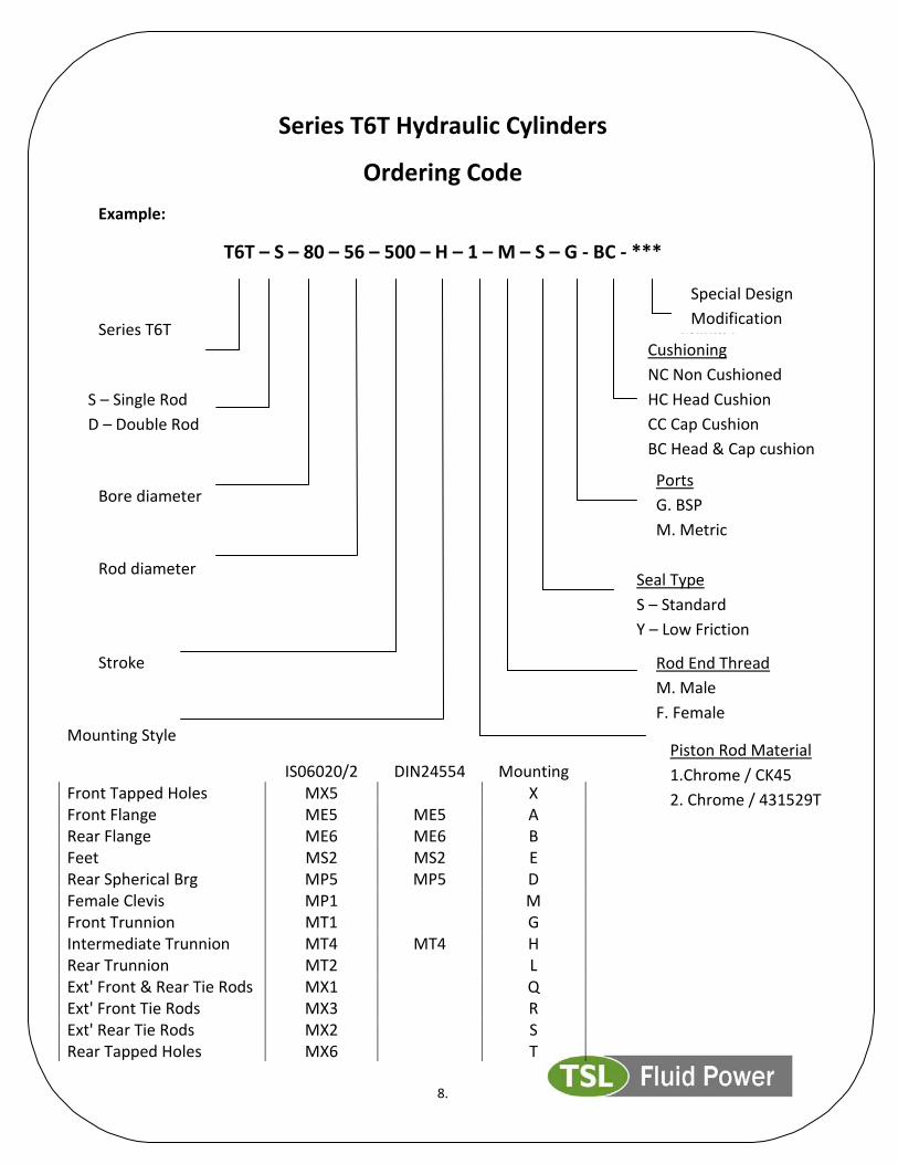
Seal Type
S – Standard
Y – Low Friction
Series T6T Hydraulic Cylinders
Ordering Code
Example:
T6T – S – 80 – 56 – 500 – H – 1 – M – S – G - BC - ***
Series T6T cylinder
Bore diameter
Rod diameter
Stroke
8.
Mounting Style
IS06020/2 DIN24554 Mounting Front Tapped Holes MX5 X Front Flange ME5 ME5 A Rear Flange ME6 ME6 B Feet MS2 MS2 E Rear Spherical Brg MP5 MP5 D Female Clevis MP1 M Front Trunnion MT1 G Intermediate Trunnion MT4 MT4 H Rear Trunnion MT2 L Ext' Front & Rear Tie Rods MX1 Q Ext' Front Tie Rods MX3 R Ext' Rear Tie Rods MX2 S Rear Tapped Holes MX6 T
Cushioning
NC Non Cushioned
HC Head Cushion
CC Cap Cushion
BC Head & Cap cushion
CCcUSHIONCushioning Ports
G. BSP
M. Metric
Rod End Thread
M. Male
F. Female
S – Single Rod
D – Double Rod
Special Design
Modification
Piston Rod Material
1.Chrome / CK45
2. Chrome / 431529T