
Department of Electronic Engineering - Run Run Shaw
80
i Department of Electronic Engineering FINAL YEAR PROJECT REPORT BEngCE-2005/06-BECE-AS-01 Bluetooth Application Development on Mobile Devices Student Name: Pang Chun Sau Student ID: Supervisor: Dr SUNG, Albert C W Assessor: Prof LI, Ping Bachelor of Engineering (Honours) in Computer Engineering
Transcript of Department of Electronic Engineering - Run Run Shaw
i
Department of Electronic Engineering
FINAL YEAR PROJECT REPORT
BEngCE-2005/06-BECE-AS-01
Bluetooth Application Development on Mobile Devices
Student Name: Pang Chun Sau Student ID: Supervisor: Dr SUNG, Albert C W Assessor: Prof LI, Ping
Bachelor of Engineering (Honours) in Computer Engineering

ii
Student Final Year Project Declaration I have read the student handbook and I understand the meaning of academic dishonesty, in particular plagiarism and collusion. I declare that the work submitted for the final year project does not involve academic dishonesty. I give permission for my final year project work to be electronically scanned and if found to involve academic dishonesty, I am aware of the consequences as stated in the Student Handbook. Project Title: Bluetooth Application Development on Mobile Devices
Student Name: Pang Chun Sau
Student ID:
Signature
Date: 4th May, 2006

iii
No part of this report may be reproduced, stored in a retrieval system, or transcribed in any form or by any means – electronic, mechanical, photocopying, recording or otherwise – without the prior written permission of City University of Hong Kong.

Page 1
Abstract
Wireless technology has been adding convenience to our lives by allowing
computing and communication devices to be used almost anywhere and to be used in
new, progressive ways. To fully utilize the benefits of wireless connectivity, a
powerful software program with good set of hardware is needed.
The project is aimed to build up a Java 2 Mobile Edition (J2ME) wireless
communication software running on mobile phones platform that allows connecting
two entitles via Bluetooth. Allowing a more efficient way for exchanging ideas, the
program supports three core functions: sharing white-board, chat room and voice
communication. All of the functions are written in specially designed codes which
greatly enhance the software’s compatibility on different phone models, which is
considered to be one of the greatest concerns when it comes to the design of this
software.
Page 2
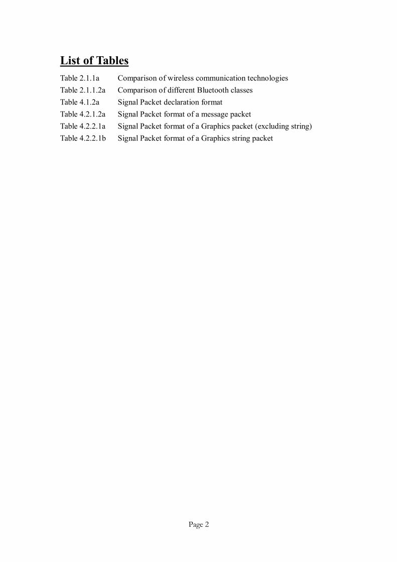
List of Tables Table 2.1.1a Comparison of wireless communication technologies Table 2.1.1.2a Comparison of different Bluetooth classes Table 4.1.2a Signal Packet declaration format Table 4.2.1.2a Signal Packet format of a message packet Table 4.2.2.1a Signal Packet format of a Graphics packet (excluding string) Table 4.2.2.1b Signal Packet format of a Graphics string packet
Page 3
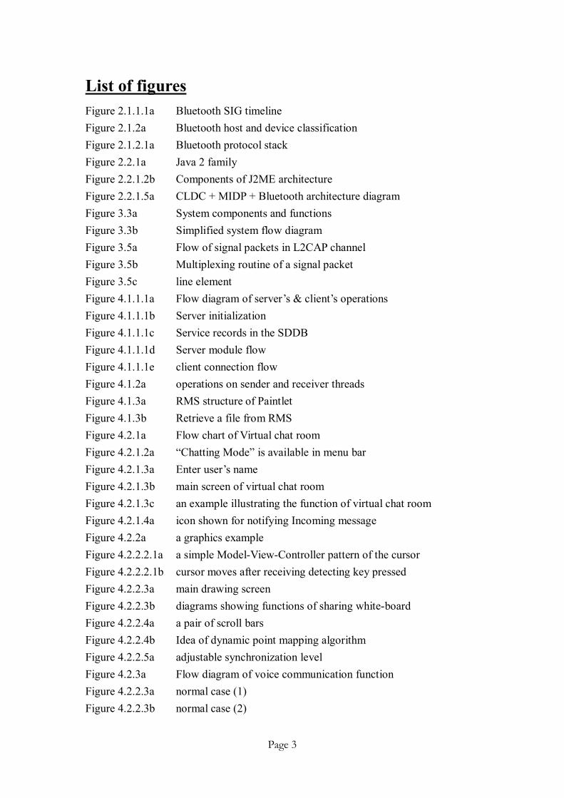
List of figures Figure 2.1.1.1a Bluetooth SIG timeline Figure 2.1.2a Bluetooth host and device classification Figure 2.1.2.1a Bluetooth protocol stack Figure 2.2.1a Java 2 family Figure 2.2.1.2b Components of J2ME architecture Figure 2.2.1.5a CLDC + MIDP + Bluetooth architecture diagram Figure 3.3a System components and functions Figure 3.3b Simplified system flow diagram Figure 3.5a Flow of signal packets in L2CAP channel Figure 3.5b Multiplexing routine of a signal packet Figure 3.5c line element Figure 4.1.1.1a Flow diagram of server’s & client’s operations Figure 4.1.1.1b Server initialization Figure 4.1.1.1c Service records in the SDDB Figure 4.1.1.1d Server module flow Figure 4.1.1.1e client connection flow Figure 4.1.2a operations on sender and receiver threads Figure 4.1.3a RMS structure of Paintlet Figure 4.1.3b Retrieve a file from RMS Figure 4.2.1a Flow chart of Virtual chat room Figure 4.2.1.2a “Chatting Mode” is available in menu bar Figure 4.2.1.3a Enter user’s name Figure 4.2.1.3b main screen of virtual chat room Figure 4.2.1.3c an example illustrating the function of virtual chat room Figure 4.2.1.4a icon shown for notifying Incoming message Figure 4.2.2a a graphics example Figure 4.2.2.2.1a a simple Model-View-Controller pattern of the cursor Figure 4.2.2.2.1b cursor moves after receiving detecting key pressed Figure 4.2.2.3a main drawing screen Figure 4.2.2.3b diagrams showing functions of sharing white-board Figure 4.2.2.4a a pair of scroll bars Figure 4.2.2.4b Idea of dynamic point mapping algorithm Figure 4.2.2.5a adjustable synchronization level Figure 4.2.3a Flow diagram of voice communication function Figure 4.2.2.3a normal case (1) Figure 4.2.2.3b normal case (2)

Page 4
List of figures (Cont’d)
Figure 4.2.2.3c Case of loss packet Figure 4.2.2.3d Case of loss acknowledgement Figure 4.2.2.3e Case of delayed packet Figure 4.2.2.3f Case of delayed acknowledgement Figure 4.2.3.4a relationship between packet size and transmission time Figure 5a difference between architecture of 2 protocols Figure 5b Feasibility on multi-connections Bluetooth application.

Page 5
Table of Contents
Abstract ------------------------------------------------------------------------------------ P.1 List of Tables ------------------------------------------------------------------------------ P.2 List of Figures ----------------------------------------------------------------------------- P.3 Table of Contents ------------------------------------------------------------------------- P.5 1. Introduction ---------------------------------------------------------------------------- P. 7 1.1 Background --------------------------------------------------------------------- P. 7 1.2 Motivation ---------------------------------------------------------------------- P. 8 1.3 Objective ------------------------------------------------------------------------ P.10
1.4 Features ------------------------------------------------------------------------- P.10 2. Background Theories ----------------------------------------------------------------- P.11 2.1 Bluetooth ------------------------------------------------------------------------ P.11 2.1.1 What is Bluetooth Wireless Technology? ----------------------------- P.11 2.1.1.1 History of Bluetooth Wireless Technology ---------------------- P.12
2.1.1.2 Bluetooth Vision ---------------------------------------------------- P.13 2.1.1.3 Bluetooth Specification -------------------------------------------- P.15
2.1.2 Overview of the Bluetooth Stack Architecture ----------------------- P.15 2.1.2.1 Bluetooth Protocol -------------------------------------------------- P.17 2.2 J2ME ---------------------------------------------------------------------------- P.20 2.2.1 What is J2ME? ------------------------------------------------------------ P.20 2.2.1.1 Configurations ------------------------------------------------------ P.22
2.2.1.2 Profiles --------------------------------------------------------------- P.23 2.2.1.3 Optional Packages -------------------------------------------------- P.24 2.2.1.4 JCP and JSR-82 ----------------------------------------------------- P.25 2.2.1.5 JABWT -------------------------------------------------------------- P.26
3. System Design ------------------------------------------------------------------------ P.29 3.1 Programming Language ------------------------------------------------------ P.29 3.2 Running Environment -------------------------------------------------------- P.30 3.3 System Architecture ---------------------------------------------------------- P.31
Page 6
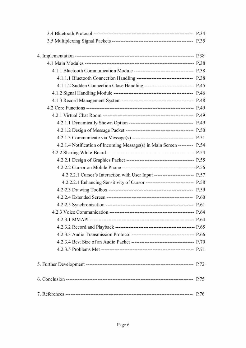
3.4 Bluetooth Protocol ------------------------------------------------------------ P.34 3.5 Multiplexing Signal Packets ------------------------------------------------- P.35 4. Implementation ------------------------------------------------------------------------ P.38 4.1 Main Modules ------------------------------------------------------------------ P.38
4.1.1 Bluetooth Communication Module ------------------------------------ P.38 4.1.1.1 Bluetooth Connection Handling ---------------------------------- P.38 4.1.1.2 Sudden Connection Close Handling ------------------------------ P.45 4.1.2 Signal Handling Module ------------------------------------------------ P.46 4.1.3 Record Management System ------------------------------------------- P.48
4.2 Core Functions ----------------------------------------------------------------- P.49 4.2.1 Virtual Chat Room ------------------------------------------------------- P.49 4.2.1.1 Dynamically Shown Option --------------------------------------- P.49
4.2.1.2 Design of Message Packet ----------------------------------------- P.50 4.2.1.3 Communicate via Message(s) ------------------------------------- P.51 4.2.1.4 Notification of Incoming Message(s) in Main Screen --------- P.54
4.2.2 Sharing White-Board ---------------------------------------------------- P.54 4.2.2.1 Design of Graphics Packet ----------------------------------------- P.55
4.2.2.2 Cursor on Mobile Phone -------------------------------------------- P.56 4.2.2.2.1 Cursor’s Interaction with User Input ------------------------ P.57 4.2.2.2.1 Enhancing Sensitivity of Cursor ----------------------------- P.58 4.2.2.3 Drawing Toolbox --------------------------------------------------- P.59 4.2.2.4 Extended Screen ---------------------------------------------------- P.60 4.2.2.5 Synchronization ----------------------------------------------------- P.61
4.2.3 Voice Communication --------------------------------------------------- P.64 4.2.3.1 MMAPI --------------------------------------------------------------- P.64
4.2.3.2 Record and Playback ------------------------------------------------ P.65 4.2.3.3 Audio Transmission Protocol -------------------------------------- P.66
4.2.3.4 Best Size of an Audio Packet -------------------------------------- P.70 4.2.3.5 Problems Met -------------------------------------------------------- P.71
5. Further Development ----------------------------------------------------------------- P.72 6. Conclusion ----------------------------------------------------------------------------- P.75 7. References ----------------------------------------------------------------------------- P.76

Page 7
Ch1 Introduction
1.1 Background
The rapid emergence of the Internet has changed the landscape of modern
computing. We are in the information age. The term “information age” came about
because of the exchange of massive amounts of data between computing devices
using wired and wireless forms of communication. We are rapidly moving toward a
world in which communications and computing are ubiquitous.
Increased dependence on the Internet and the need to stay connected from
anywhere at all times has led to advances in mobile computing and communications.
We have been communicating without wires for some time with satellites, cordless
phones, cellular phones, and remote-control devices. In recent years the wireless
communication industry has come into an explosive growth and any short-range
wireless standards are developed as a result of it. The 3 main ones out of them are
Infrared, Bluetooth wireless technology, and wireless local are network (WLAN)
which is also known as IEEE 802.11.
There is no denying that wireless communications allow computing and
communication devices to be used almost anywhere and to be used in new,
progressive ways. The increase in wireless mobile Internet devices is proof that
wireless connectivity is pervasive. Research and development (R&D) has been

Page 8
conducting continuously and powerful software based on powerful wireless
technology has been coming.
1.2 Motivation
Bluetooth wireless technology allows us to exchange data in a convenient way.
Many software houses would like to develop some useful applications and systems so
as to introduce to us the how Bluetooth wireless technology can be applied and help
in different ways such as sending and receiving files, playing audio with a Bluetooth
headset, providing multi-player games, etc. Most of them are accessible through the
internet.
Great emphasis has been put on a specific area on how Bluetooth technology can
allow users to exchange ideas on mobile devices effectively. I found that, however,
none of the existing software can actually provide a full set of solutions that enable
achievement of this. For example, some applications support chatting function but
does not support file sharing; some applications support a good set of functions but do
not posses a good compatibility such that they can only run on a specific device
model. Such weakness and constraints, for sure, would not be appreciated since they
really lower down much practicability on the whole applications. It arouses my
interests in developing an application on mobile phones to overcome the problems.

Page 9
Mobile phones instead of personal digital assistance (PDA) or other devices are
selected as the targeted platform. It is because the marketing ratio of mobiles phones
is found to be larger than that of PDA and pagers or other devises, which basically
means the probability for a randomly chose person to have at least one
Bluetooth-enabled mobile phone is larger than that for s/he to have at least one
Bluetooth-enabled PDA or any other Bluetooth-enabled device, assumed that all
devices are equally likely to be Bluetooth-enabled.
1.3 Objective
My project is aimed at developing a program that allows users for exchanging
their ideas on mobile phones effectively. The objects of it are:
l Understand the concepts of Bluetooth wireless technology and the
possible usage of it.
l Develop a Bluetooth application that provides a lot of useful functions
so as to allow users to present and exchange their ideas on mobile
phones.
l Ensure the compatibility of the program on different mobile phones’
platforms.

Page 10
1.4 Features:
The program, named as Paintlet, is characterized with the following features and
benefits:
l Functionality – Paintlet provides lots of specially designed useful functions
for users to exchange their ideas with each other accurately and effectively.
l Compatibility – The program basically runs on all types of
Bluetooth-enabled mobile phones;
l Reusability – Made with the best use of inheritance as a result of
object-oriented programming, mother classes are designed to be as generic
as possible;
l Offline Workability – Operates in both connected and disconnected mode
(some functions restricted);
l Reliability – Special transmission protocol is specially designed for
guaranteeing Quality of Service (QoS);
l User Friendliness – Simple and clear visual interface are implemented in
Paintlet.

Page 11
Ch2 Background Theories
This chapter would give readers some background theories that may help for
reading latter chapter. Basic background theories and technical terms will be
described here as simple as it could. It should be noticed that concepts may be
repeated in the later chapters and some new background theories will still be
continuously be provided even after this chapter where appropriate.
2.1 Bluetooth
2.1.1 What is Bluetooth Wireless Technology?
Bluetooth wireless technology is an open specification for a low-cost, low-power,
short-range radio technology for ad hoc wireless communication of voice and data
anywhere in the world. It is an open specification which means the specification is
publicly available and royalty free. Let’s examine the differences among the 3
wireless communication technologies.
Feature & Function IrDA Bluetooth Wireless LAN Connection Line of sight Spherical Spherical Spectrum Optical 850-900 nm RF 2.4 Ghz RF 2.4 Ghz Transmission power 40-500 mW/Sr 10-100 mW 100 mW Maximum data rate ~ 9600 bps 1 Mbps > 11 Mbps Range 1 m 10-100 m 100 m Table 2.1.1a Comparison of wireless communication technologies

Page 12
Bluetooth, as a short-range radio technology that operates at 2.4 Ghz, allows
devices to communicate over the air using radio waves at a distance of 10 meters (m).
With a Bluetooth module of higher class and higher transmission power, the range
increases to approximately 100 m. The radios are low power and are thus suited for
portable, battery-operated devices because communication is within a short range.
Such features make Bluetooth become a hot topic in research and development (R&D)
in mobile areas.
2.1.1.1 History of Bluetooth Wireless Technology
Bluetooth got its name from King Harald Blätand (Bluetooth) of Denmark. His
most notable accomplishment was that he united Denmark and Norway under
Christianity in the 10 century.
In 1994, Ericsson conducted the first research studies of a wireless technology
link mobile phones and accessories. The engineers looked at a low-power and
low-cost radio interface to eliminate cables between the devices. But the engineers
also realized that for the technology to be successful, it has to be an open standard and
not a proprietary one. Years later in 1997, Ericsson formed the Bluetooth Special
Interest Group (Bluetooth SIG) so that other companies could use and promote the
technology. At that time, the Bluetooth SIG consisted of the following promoter
Page 13
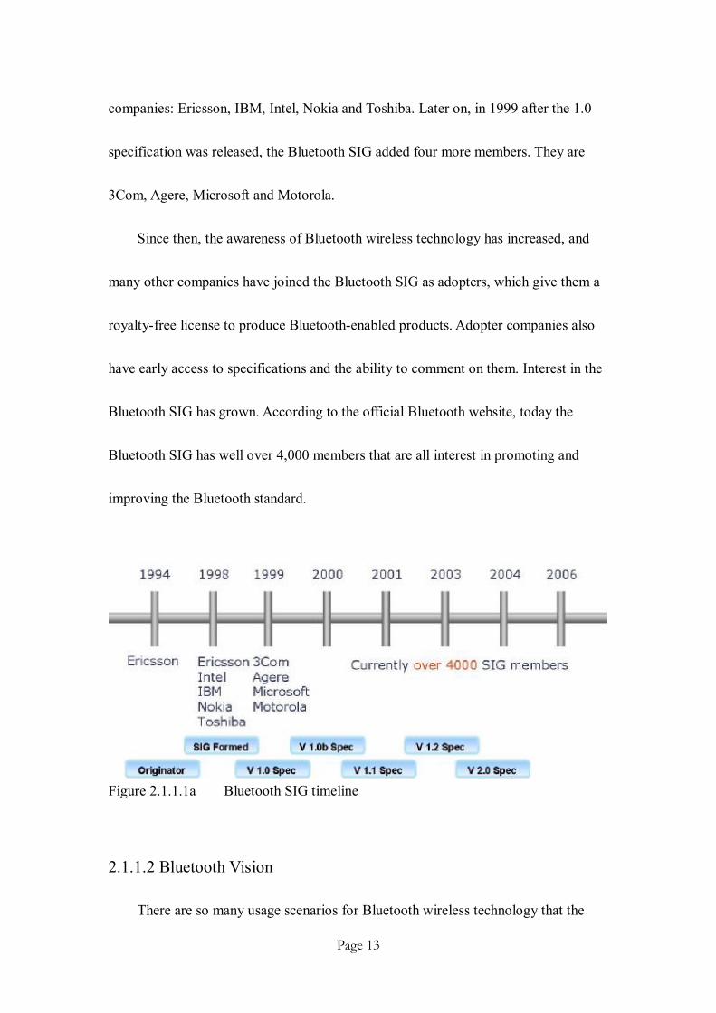
companies: Ericsson, IBM, Intel, Nokia and Toshiba. Later on, in 1999 after the 1.0
specification was released, the Bluetooth SIG added four more members. They are
3Com, Agere, Microsoft and Motorola.
Since then, the awareness of Bluetooth wireless technology has increased, and
many other companies have joined the Bluetooth SIG as adopters, which give them a
royalty-free license to produce Bluetooth-enabled products. Adopter companies also
have early access to specifications and the ability to comment on them. Interest in the
Bluetooth SIG has grown. According to the official Bluetooth website, today the
Bluetooth SIG has well over 4,000 members that are all interest in promoting and
improving the Bluetooth standard.
Figure 2.1.1.1a Bluetooth SIG timeline
2.1.1.2 Bluetooth Vision
There are so many usage scenarios for Bluetooth wireless technology that the

Page 14
technology will likely be put to wide use, such as data voice access points, cable
replacement and personal ad-hoc networks.
There are factors that affect the usage scenario(s) of a device in reality. One
factor of them that distinguishes various Bluetooth devices is their connection
capabilities. If a Bluetooth device can only support point-to-point communication,
then it can only communicate to a single Bluetooth device at a time. This is exactly
the case of Bluetooth specification in common mobile phones until the exposure of v
2.0. For example, a Nokia 3230 phone can’t share files to other devices using
Bluetooth in case it has connected to a Bluetooth Audio Headset already. This adds
difficulties for developers to build multi-players Bluetooth applications.
Another factor is concerning the power classes of Bluetooth hardware devices.
Up to the time when this report is being written, there are a total of three power
classes that describes the device classes and their capabilities.
CLASS POWER RATING RANGE Class 1 100 mW 100 meters Class 2 2.5 mW 20 meters Class 3 1 mW 10 meters
Table 2.1.1.2a Comparison of different Bluetooth classes
In addition to the covering range and power rating, power classes would also
affect the maximum transmission rate of Bluetooth hardware devices actually. A

Page 15
higher class Bluetooth module would allow a faster data transmission between or
among devices than a lower class one.
2.1.1.3 Bluetooth Specification
The Bluetooth specification is the result of cooperation by many companies
under the Bluetooth Special Interest Group (SIG). It defines the over-the-air behavior
to ensure compatibility of Bluetooth devices from different vendors. It defines the
complete system from the radio up to the application level, including the software
stack.
At the highest level, the specification (version 1.1, Nokia series 6600) is split
into two volumes. Volume 1 is the core specification and describes the protocol stack
and related items such as testing and qualification. The Bluetooth protocol stack is
defines as a series of layers somewhat analogous to the familiar Open System
Interconnect (OSI) standard reference for communication protocol stacks. Each layer
of the protocol stack represents a different protocol and is separately described in the
core specification.
2.1.2 Overview of the Bluetooth Stack Architecture
The Bluetooth protocol stack can be broadly divided into two components: the

Page 16
Bluetooth host and the Bluetooth controller. The Host Controller Interface (HCI)
provides a standardized interface between the Bluetooth host and the Bluetooth
controller.
Figure 2.1.2a Bluetooth host and device classification
The Bluetooth host is known as the upper-layer stack and usually is implemented
in software. It is generally integrated with the system software or host operating
system (OS). Bluetooth profiles are built on top of the protocols. They are generally in
software and run on the host device hardware. The Bluetooth host would be integrated
with the operating system.
The Bluetooth radio module or controller usually is hardware modules like a PC
card the plugs into a target device. More and more devices have the Bluetooth

Page 17
controller built into the device. The upper stack interfaces to the Bluetooth radio
module via the HCI. The Bluetooth radio module usually interfaces with the host
system via one of the standard input/output (I/O) mechanisms, such as PCMCIA,
UART and USB. Although the Bluetooth host and the Bluetooth controller
classifications apply to most devices, the two are integrated in some devices, headsets,
for example, and HCI is not used.
2.1.2.1 Bluetooth Protocols
Below figure show s that there are several protocols (filled in grey) defined in the
Bluetooth speciation. There are Object Exchange Protocol (OBEX), Service
Discovery Protocol (SPD), RMCOMM and Logical Link Control and Adaptation
Protocol (L2CAP) addressed by Java APIs for Bluetooth wireless technology
(JABWT, where API stands for application programming interface).

Page 18
Figure 2.1.2.1a Bluetooth protocol stack
The baseband and link control layer enable the physical RF link between
Bluetooth units making a connection. The baseband handles channel processing and
timing, and the link control handles the channel access control. There are two
different kinds of physical links: synchronous connection oriented (SCO) and
asynchronous connectionless (ACL). An ACL link carries data packets, whereas an
SCO link supports real-time audio traffic. L2CAP is a circuit-switching protocol and
is an example of the former one while RFCOMM, a circuit-switching protocol,
belongs to the later one. They will be described in the following paragraphs.
Audio is really not a layer of the protocol stack but it is shown here because it is

Page 19
uniquely treated in Bluetooth communication. Audi data is typically routed directly to
and from the baseband layer over and SCO link. Of course, if a data channel is used
(e.g., in VoIP applications), audio data will be transmitted over an ACL link.
Logical Link Control and Adaptation Protocol (L2CAP) shields the upper-layer
protocols from the details of the lower-layer protocols. It multiplexes between the
various logical connections made by the upper layers. Basically, it is a protocols
designed to transport data packets on its own. It is in fact what we use in the program
developed. The later chapter will give more details on reasons of this.
SPD provides a means for applications to query services and characteristics of
services. Unlike in an LAN connection, in which one connects to a network and then
finds devices, in a Bluetooth environment one finds the device before one finds the
service. In addition, the set of services available may change in an environment, when
devices are motion. Hence SDP is quite different form service discovery in traditional
network-based environments. SPD is built on top of L2CAP. However, it should be
noticed that SDP is for the system’s use only and is thus not available for developers
to build on it.
The RFCOMM protocol provides emulation of serial ports over L2CAP. It
provides transport capabilities for upper-layer services that use a serial interface as a
transport mechanism. RFCOMM provides multiple concurrent connections to one

Page 20
device and provides connections to multiple devices.
It should be noticed that most phones in the markets nowadays do not support
OBEX though they support the others (excluding SDP as mentioned previously). This
adds difficulties to ensure the stability and reliability of cases when large file(s) is/ are
needed to be transferred from one device to another device. To handle this, own
OBEX mechanism has to be built.
2.2 J2ME
2.2.1 What is J2ME?
J2ME is the short form of Java 2, Micro Edition. It is the Java platform for consumer
and embedded devices such as mobile phones, pagers, personal organizers, television
set-top boxes, automobile entertainment and navigation systems, Internet television,
and Internet-enabled phones.
Figure 2.2.1a Java 2 family

Page 21
J2ME is one of the three platform editions. The other two platforms are Java 2
Platform, Enterprise Edition (J2EE) and Java 2 Platform, Standard Edition (J2SE).
The remaining Java Card specifications enable Java technology to run on smart cards
and other devices with more limited memory than a low-end mobile phone. These
groupings are needed to tailor the Java technology to different areas of today’s vast
computing industry.
The J2ME platform brings the power and benefits of Java technology (code
portability, object-oriented programming, and a rapid development cycle) to consumer
and embedded devices. The main goal of J2ME is to enable devices to dynamically
download applications that leverage the native capabilities of each device. Consumer
and embedded space covers a range of devices from pagers to television set-top boxes
that vary widely in memory, processing power, and I/O capabilities. To address this
diversity, the J2ME architecture defines configurations, profiles, and optional
packages to allow for modularity and customizability. Figure 2.1.1.1a shows the
higher-level relations between the layers of the J2ME architecture. The layers are
explained further in the next section.

Page 22
Figure 2.2.1.2b Components of J2ME architecture
2.2.1.1 Configurations
A Java virtual machine interprets the Java byte codes generated when Java
programs are compiled. A Java program can be run on any device that has a suitable
virtual machine and a suitable set of Java class libraries.
Configurations are composed of a Java virtual machine and a minimal set of
class libraries. The Java virtual machine usually runs on top of a host operating
system that is part of the target device’s system software. The configuration defines
the minimum functionality for a particular category or grouping of devices. It defines
the minimum capabilities and requirements for a Java virtual machine and class
libraries available one all devices of the same category or grouping. Currently, there
are two J2ME configurations: the Connected, Limited Device Configuration (CLDC)
and the Connected Device Configuration (CDC).
The CDLC focuses on low-end consumer devices and is the smaller of the two

Page 23
configurations. Typical CLDC devices, such as personal organizers, mobile phones,
and pagers, have slow processors and limited memory, operate on batteries, and have
only intermittent network connections. A CLDC implementation generally includes a
kilobyte virtual machine (KVM). It gets its name because of its small memory
footprint, which is on the order of kilobytes. The KVM is specially designed for
memory constrained devices.
The CDC focuses on high-end consumer devices that have more memory, faster
processors, and greater network bandwidth. Typical examples of CDC devices are
television set-top boxes and high-end communicators. CDC includes a virtual
machine that conforms fully to the Java Virtual Machine Specification. CDC also
includes a much larger subnet of the J2SE platform than does CLDC.
2.2.1.2 Profiles
Configurations do not usually provide a complete solution. Profiles add the
functionality and the APIs required which are required to complete a fully functional
runtime environment for a class of devices. Configurations must be combined with
profiles that define the higher-level APIs for providing the capabilities for a specific
market or industry.
It is possible for a single device to support several profiles. Examples of them are

Page 24
Mobile Information Device Profile (MIDP), Foundation Profile (FP), and Personal
Profile (PP). The Bluetooth profiles defined previously are not to be confused with the
J2ME profiles discussed here. The two profiles are not related. Bluetooth profiles
refer to a set of functionality of the Bluetooth protocols for a particular usage case.
J2ME profiles are a set of APIs that extend the functionality of a J2ME configuration.
As related to background of the program, only MIDP will be described here.
The first profile that was created was MIDP. This profile is designed for mobile
phones, pagers, and entry-level personal organizers. MIDP combined with CLDC
offers core application functionality, such as a user interface, network capability, and
persistent storage. MIDP provides a complete Java runtime environment for mobile
information devices. MIDP applications are called MIDlets which is a class defined in
MIDP and is the superclass of all MIDP applications.
2.2.1.3 Optional Packages
Many J2ME devices include additional technologies such as Bluetooth wireless
technology, multimedia, wireless messaging, and database connectivity. Optional
packages were created to fully leverage these technologies through standard Java
APIs. Device manufacturers can include these optional packages as needed to fully
utilize the features of each device. This is why some phone models may support Java
Page 25
API for Bluetooth wireless technology (JABWT) but do not supports OBEX
transmission protocol as mentioned previously.
In addition to the configurations, profiles, and optional packages, device
manufacturers are able to define additional Java classes to take advantage of features
specific to the device. The classes are called licensee open classes (LOCs). And LOC
defines classes available to all developers. Licensee closed classes (LCCs) defines
classes available only to the device manufacturer. Program using these classes may
not be portable across devices having the same configuration and profiles. Example of
them is the Nokia UI API, which can only be run on Nokia phones but not other
platforms liked Sony Ericsson and Motorola. Such problem must come into our
concerns when we design and develop Paintlet, or otherwise it is not portable enough
such that it would only run on a specific platform.
2.2.1.4 JCP and JSR-82
Standard APIs in the Java programming language are defined though the Java
Community Process (JCP). The JCP coordinates the evolution of the Java
programming language. Each new API is developed as a Java Specification Request
(JSR). All J2ME configurations, profiles, and optional packages are defined as JSRs.

Page 26
JCP standardizes the Java APIs for Bluetooth wireless technology under JSR-82. The
expert group that defined JABWT consisted of 18 companies and three individuals.
The companies include Extended Systems, IBM, Motorola, Sony Ericsson Mobile
Communications, Smart Fusion, Nokia, etc.
2.2.1.5 JABWT
Previous section told us some background about JSR-82, which is an official
standardized name of JABWT. In this section, we will learn more about what it is
actually.
The following are some of the key characteristics of a formal JABWT:
l It uses the CLDC generic connection framework.
l It requires a Bluetooth Control Center (BCC) for system control.
l It provides a definition for service registration.
l It defines an OBEX API that is transport independent.
The functionality provided by JABWT falls into three major categories:
l Discovery
l Communication
Page 27
l Device management
Discovery includes device discovery, service discovery, and service registration.
Communication includes establishing connections between devices and using those
connections for Bluetooth communication between applications. These connections
can be made over several different protocols, namely RFCOMM, L2CAP, and OBEX.
Device management allows for managing and controlling these connections. It deals
with managing local and remote device states and properties. It also facilitates the
security aspects of connections. JABWT is organized into these three function
categories.
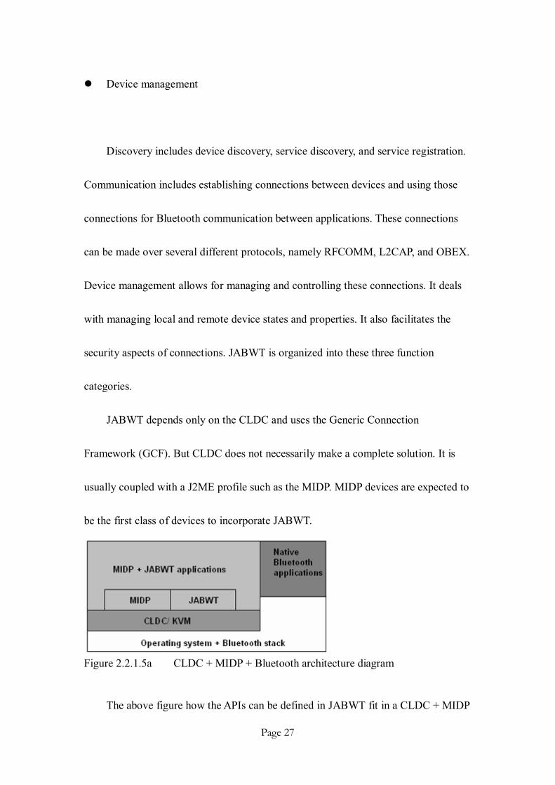
JABWT depends only on the CLDC and uses the Generic Connection
Framework (GCF). But CLDC does not necessarily make a complete solution. It is
usually coupled with a J2ME profile such as the MIDP. MIDP devices are expected to
be the first class of devices to incorporate JABWT.
Figure 2.2.1.5a CLDC + MIDP + Bluetooth architecture diagram
The above figure how the APIs can be defined in JABWT fit in a CLDC + MIDP

Page 28
architecture. Although shown here on an MIDP device, JABWT does not depend on
MIDP APIs. The lowest-level block operating system contains the host part of the
Bluetooth protocol stack and other libraries used internally and by native application
of the system. Native Bluetooth applications interface with the operating system
directly. The CLDC/KVM implementation sits on top of the host system software.
This block provides the underlying Java execution environment on which the
higher-level Java APIs can be built. The figure actually shows two such APIs that can
be built on top of CLDC. They are JABWT, the set of APIs specified by JSR-82 and
MIDP, the set of APIs defined by JSR-378 and JSR-118.

Page 29
Ch3 System Design
3.1 Programming Language
The most common languages used to develop mobile applications are C++ and
J2ME. The former one is powerful but platform dependent which makes it not an
ideal programming language. The later one is chose as the programming language
because the Java API is standard such that programs built on the codes can work
across many hardware platforms if the minimum requirement of the system is
satisfied. That is, the portability of codes and hence the capability of the program will
be greater by using J2ME as the programming language. An example is that the
JABWT specification provides a standard set of APIs for developing Bluetooth
applications, which is going to be portable to run on a wide range of devices with a
wide range of Bluetooth radio modules and Bluetooth protocol stacks.
In fact, the Java language provides several other benefits in addition to
portability mentioned:
l Security: services and applications cannot be subverted
l Interface: standards with better user interfaces and that support
sophisticated user interaction.
l Robustness: fewer faults, fewer recalls
l Fast development: faster time-to-market

Page 30
l Better runtime management: ability to dynamically expand a program’s
functionality during execution by loading classes at runtime.
3.2 Running Environment
Paintlet has been tested on emulators and real phones.
The emulators used include Sony Ericsson SDK 2.2.3 for the Java(TM) ME
Platform and Sun J2ME Wireless Toolkit 2.2 (patch 200511).
For real phones, only Sony Ericsson W500, Nokia 6630, Nokia 6680, Nokia
3230 have been tested because of the resources limitation. However, the problem
should work on other real phone models if they fulfill the minimum requirements of
the program.
Basically, the phones must support the execution of MIDP applications (*.jar)
and include the following J2ME optional packages in order to run the program on
them successfully. They are:
l CLDC 1.0 (JSR-35)
l MIDP 2.0 (JSR-118)
l MMAPI (Mobile Media API, JSR-135)*
l JABWT (JSR-82)
l 200 Kbytes free memory.

Page 31
* The phones hardware must also support recording and playing wav audio file.
Otherwise, some features of the program will not function well.
3.3 System Architecture
The program is built based on a server-client structure. That is, at least one server
must be presented so that other clients can connect to it for accessing services
provided. So far, the system supports only one-to-one connection. It is hoped that it
will support multiple connections in the future after further development.
The program consists of three main components and three core functions
controlled by separate Java classes.
Figure 3.3a System components and functions
Main components:
l Bluetooth communication module

Page 32
l Signal handling module
l Record Management System
Core functions:
l Virtual chat room
l Sharing white-board
l Audio communications
All of the functions above are handled and implemented part by part. This allows
greater reusability of codes and greater independency of classes. In addition, time
control to implement the project will be better.
They will be described in details. Before that, let’s see a simplified flow diagram
showing how the system runs actually.

Page 33
Figure 3.3b Simplified system flow diagram
Here are the steps involved:
1. Two devices available with one initialized as a Bluetooth server. *
2. The other side acts as a Bluetooth client.
3. Client side performs device discovery followed by service discovery.
4. Establish a Bluetooth connection between two devices.
5. Synchronize current screen and settings to each other immediately after
establishment of Bluetooth connection.
6. Both sides can perform function they like and system will automatically
synchronize the operation(s) done.
7. If one side wants to close the connection, s/he may do it by sending a request
closing signal to other side so that they can both close the BT connection at the

Page 34
same time.**
* The program allows operation in single-user mode. That is, even if Bluetooth
connection is not established between it and the remote device, the user is still able to
draw graphics and save it in offline mode.
** Paintlet has been implemented with a powerful function such that even if one side
does not send the request closing connection signal to other device before closing the
Bluetooth connection, the other side is still able to detect it with a short delay. The
delay is typically 0.2 – 0.5 seconds.
3.4 Bluetooth Protocol
As described previously, there are actually three communication protocols
defined by JSR-82 for developers to build application with any of them. They include
OBEX, RFCOMM and L2CAP. In Paintlet, only L2CAP is used.
The reason why OBEX and RFCOMM are not used is similar. OBEX is
powerful in providing a reliable data transfer for an object (probably a file) of any size,
but is not supported in most phone models. RFCOMM is powerful in providing a
stream connection that allows multiple devices to communicate with less overheads
and delay. However, it has been tested that Nokia phones with Symbian OS do not

Page 35
give a stable performance for applications using RFCOMM to communicate with
each others. Sometimes, the RFCOMM would be cut automatically after a few
second.
In contrast, L2CAP is being supported well in all phone models tested, including
Sony Ericsson K750i, Nokia 3230, Nokia 6680, etc. It is good to be used in Paintlet
because it allows a signal to be packed into a packet form, which allows the signal
handling module of the program to multiplex different signals to different classes for
processing in a bi-directional way. The details will be discussed in the following
section. The maximum size of a data packet is determined by the Maximum
transmission unit (MTU) value of devices, which may vary from phones to phones
models. For a typical mobile phone, MTU is about 700 bytes.
3.5 Multiplexing Signal Packets
Server and receiver in Paintlet communicate with each other using signal packets
which are stored in both sides using Vector. Different types of signal packets will be
routed to different modules for processing. For example, request closing connection
signal mentioned in figure 3.3a is handled by a Bluetooth communication module.
The advantage of class hierarchy is taken to support this multiplexing feature.
The idea is shown below:

Page 36
Figure 3.5a Flow of signal packets in L2CAP channel
Each side has a sender and a receiver thread running simultaneously in the
background, allowing sending and receiving of signal packets at the same time
through a single L2CAP channel. Paintlet is composed of groups of classes running
independently to handle the signal packets correspondingly.
The format of signal packets generated in the sender side is well defined. It
consists of ten parameters which make it sufficient enough to describe the operation
requesting. The first parameter “action” is actually the header of that packet.
Figure 3.5b Multiplexing routine of a signal packet
When a signal packet is received, its type (for example, system signal, graphics,
text, etc.) is determined by header of it. Headers are actually an integer identifying the
type of signal packet. Different signal packets will be routed to different processing

Page 37
module respectively.
Such signal packet could be complicated comparing to just draw the graphics on
the screen. However, there are obvious benefits of using such class structure.
Firstly, the graphics element can be treated independently. By storing all sent and
received signal packets, Paintlet is able to do operation on specific graphics element
without altering the other ones. An example of it is that we are able to undo the
current operation without causing the other element to be modified, which is called
the layer effect.
Secondly, such representation algorithm allows the graphics elements to be
drawn (shown) and synchronize very effectively. The size
required to describe a graphics element is greatly
reduced. For example, if traditional way (record the
every pixel’s status) is used to represent the line element shown in figure 3.5c using
true-color representation, it may take up to 675 bytes (15x15x3 bytes) to represent
that of length 21 pixels. In the contrast, the size required to represent such element
after applying the algorithm reduce to 26 bytes. The reducing factor is large, which
allows the graphics to be shown and synchronize effectively. Details of the algorithm
will be provided in the later section when describing the implementation of sharing
white-board.
Figure 3.5c, line element

Page 38
Ch4 Implementation
4.1 Main Modules
4.1.1 Bluetooth Communication Module
The Bluetooth communication module is formed by classes controlling three
mechanisms: a) Bluetooth connection setup; b) Sudden connection close handling.
They will be discussed in details:
4.1.1.1 Bluetooth Connection Handling
The Bluetooth connection process involves two devices, one being a client and
one being a server. Figure 4.1.1.1a shows the whole flow diagram of both server’s and
client’s operations. Device 1 is going to be a server and device 2 is going to be a
client.

Page 39
Figure 4.1.1.1a Flow diagram of server’s & client’s operations
Server:
One of the two devices must initialize itself as a Bluetooth server and waits for
clients to connect.
Before all, the device must turn on their Bluetooth function and set itself to be

Page 40
Figure 4.1.1.1b Server initialization
Figure 4.1.1.1c Service records in the SDDB
fully discoverable, which means that other devices are able to search for it and
attempt to connect it. If this step is not
done before attempt to start server
initialization process, an error message
will be shown on screen. After the
previous step, user can then choose to start
the device as server and ready for
establishment for Bluetooth connection
between it and client device.
In such case of run-before-connect
service, clients have no possibility of
connecting until the server calls
acceptAndOpen(). For this reason, the
implementation must not add a service
record which is a record generated by
system for identifying the current service
to the Service Discovery Database (SDDB) until acceptAndOpen() is called. SDDB is
a database for storing all the services available for clients to discoverer. A client

Page 41
cannot connect to a running server if the server does not register its service in SDDB,
no matter it is set to be discoverable by client or not.
Figure 4.1.1.1d Server m
odule flow
Page 42
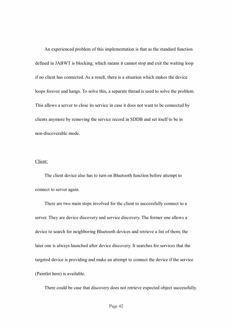
An experienced problem of this implementation is that as the standard function
defined in JABWT is blocking, which means it cannot stop and exit the waiting loop
if no client has connected. As a result, there is a situation which makes the device
loops forever and hangs. To solve this, a separate thread is used to solve the problem.
This allows a server to close its service in case it does not want to be connected by
clients anymore by removing the service record in SDDB and set itself to be in
non-discoverable mode.
Client:
The client device also has to turn on Bluetooth function before attempt to
connect to server again.
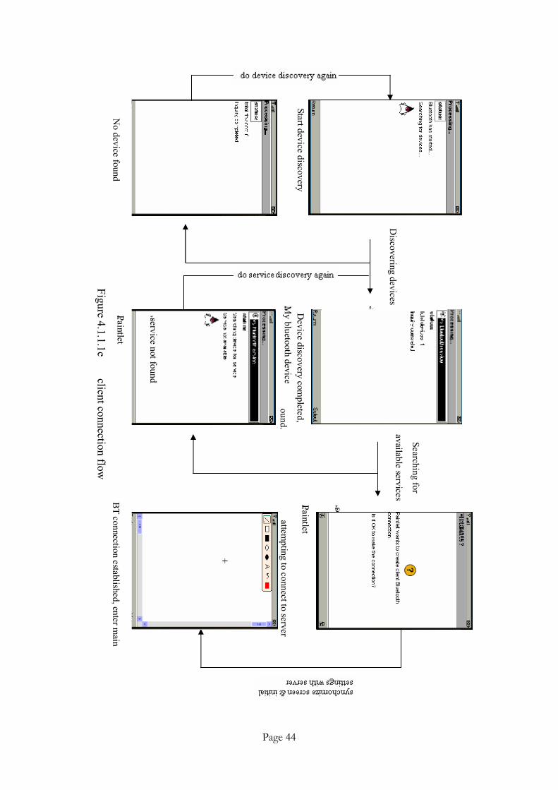
There are two main steps involved for the client to successfully connect to a
server. They are device discovery and service discovery. The former one allows a
device to search for neighboring Bluetooth devices and retrieve a list of them; the
later one is always launched after device discovery. It searches for services that the
targeted device is providing and make an attempt to connect the device if the service
(Paintlet here) is available.
There could be case that discovery does not retrieve expected object successfully.

Page 43
For example, the device discovery process may fail to discovery any device if none of
a Bluetooth-on device is within the discoverable area. Also, the service discovery
process may also fail if the server does not provide service which the client expects.
In both case the corresponding discovery process should be done again, otherwise
Bluetooth connection cannot be established successfully.
If any side of two devices wants to close connection, it should send a “request to
close connection” signal to notify the other side of this event before disconnection.
This architecture is to ensure that both sides can close the Bluetooth connection at the
same time.
Page 44
Device discovery com
pleted,
“ My bluetooth device
” is f
ound.
Discovering devices
Start device discovery “ Paintlet
” service is found and client is
attempting to connect to server
“ Paintlet
” service not found
Searching for
available services
No device found
BT connection established, enter m
ain Figure 4.1.1.1e
client connection flow

Page 45
4.1.1.2 Sudden Connection Close Handling
There may be a case when sudden connection closes at server side or client side.
For example, if the device is out of power the device will shut down automatically
and the Bluetooth connection will close. So we have to handle such situation by
notifying the other side of this event.
JABWT does not provide any API to detect such case directly. Thus we have to
seek on other method to solve this problem.
An exception method is helpful. It is based on that fact that the receiver thread is
actually continuously running and attempting to read data from remote device in the
background. So we can implement an exception function that catches the I/O error
possibly caused by the sudden close of Bluetooth connection and notify the main
program to handle this. The delay should be less than 0.5 second. The receiver thread
has been embedded with a signal interpretation function that converts the bytes
received from the L2CAP channel to the format of a signal packet which is then
handled by a (or a set of) suitable class(es).The operation does not only include
closing of connection automatically and notify the user of this, but also freeing
available memory spaces that were once occupied by the connection-controlling
variables which become “garbage” now.

Page 46
4.1.2 Signal Handling Module
It comprises two simultaneously running threads of sender and receiver which
allow handling of different signal packet. Thread structure allows a non-blocking
method to send and receive messages which increase the efficiency of the program.
Sender thread coverts the signal packet generated by classes into bytes format
and send it to remote device through a L2CAP Channel. It also ensures the size of a
packet not exceeding the maximum allowable value, i.e. MTU value negotiated
between two devices.
Receiver thread has been embedded with a signal interpretation function that
converts the bytes received from the L2CAP channel back to the format of a signal
packet which is then handled by a (or s set of) suitable class(es).
Figure 4.1.2a operations on sender and receiver threads

Page 47
Identification and handling of packets is based on the header of the file. To know
more about his, let’s look at the declaration format of a signal packet.
Parameters Primitive type
action integer s_xc integer s_yc integer e_xc integer e_yc integer param integer R integer G integer B integer msg String Table 4.1.2a Signal Packet declaration format
Generation of correct type of signal packets is not complicated and should be
smooth, but not all packets can go through the channel we don’t take care on the max
size of a packet since there is a restriction on MTU which disallow a packet of size
greater than MTU to go through the L2CAP channel. Typical value of MTU, as
mentioned, is about 700 bytes.
In this case, it is the sender thread’s responsibility to control and test the length
of every packet sending out. In case the packet’s size exceeds the limit, a window will
be prompted and shows corresponding error messages.
4.1.3 Record Management System

Page 48
Figure 4.1.3a RMS structure of Paintlet
Figure 4.1.3b Retrieve a file from RMS
Record management system (RMS) is a system built to save, load and delete
record dynamically. The word “dynamically” here means that the number of records,
despite the size’s limitation of internal memory, can be theoretically.
Two independent record
stores are built to store two kinds
of data. The first one include
system settings, graphics &
message text while the other one stores audio
files received from remote device using audio
communication function that will be described
later.
Use of the RMS is practical, as it does
not limit the number of records, and provides
a efficient way to save the current system
status so as to provide a possible way for
us to get into the previously saved state, and play the stored voice message received.

Page 49
4.2 Core functions
4.2.1 Virtual Chat Room
The function of a virtual chat room should be familiar – to communicate with
others using text. It is just liked what we do to communicate with other people using
ICQ, MSN Messenger, etc. It is used when we want to send message(s) to or receive
message(s) from the connected device.
Let’s take a look on flow diagram of virtual chat room.
Figure 4.2.1a Flow chart of Virtual chat room
4.2.1.1 Dynamically Shown Option
“Chatting Mode” is unavailable when the device is not connected with other one.
This is to prevent a misleading situation that the function “Chatting Mode” can be

Page 50
Figure 4.2.1.2a “Chatting Mode” is available in menu bar
used and chat with someone even if it is not yet connected to any one. We shall see
the function “Chatting Mode” available for us
to select in the menu bar as shown in figure
4.2.1.2 Design of Message Packet
The design of a message packet has a
direct relation with the constraints set on
virtual chat room. It is because as the
maximum size of a packet is fixed, the maximum length of user name will be
disproportional to that of the message. Since the message part should be the one
concerned most, it should be longer enough for user to input information. The
resulting design of a message packet is as shown below.
Parameters Description
action Equals to 31, header type s_xc 0 s_yc 0 e_xc 0 e_yc 0 param 0 R 0 G 0 B 0 msg Contents of message with user name Table 4.2.1.2a Signal Packet format of a message packet

Page 51
Figure 4.2.1.3a Enter user’s name
Figure 4.2.1.3b main screen of virtual chat room
4.2.1.3 Communicate via Message(s)
User has to enter his/her name before
being able to send or receive a message. The
name input here will be attached with every
single message sent and be shown on remote
device interface.
There are extra functions available for
user to erase the wrongly input name by
choosing [Erase]. If the user has confirmed
that the name inputted is okay, s/he may
press [Okay] to continue.
Having finished entering user name,
user will be directed to a screen as figure
4.2.1.3b shown. This is the main screen of
the virtual chat room where user is able to
send and receive message(s) conveniently.
The interface is clear enough such

Page 52
that even a naive user can catch up using this function quickly. Besides the core
button [Send] that allows user to send out message, there are extra buttons [Clear you
message] for clearing currently inputting message, [Clear all history] for clearing the
saved histories and [Canvas Mode] for user to switch the screen from virtual chat
room to main program screen, which is called a canvas.
To illustrate the function of virtual chat room more effectively, I have captured
some screen shots showing a case when the user “Johnny” is sending a piece of
message with contents “Hi boy~” to the remote device’s user “Peter”.

Page 53
Johnny Peter
sending a message
Figure 4.2.1.3c an example illustrating the function of virtual chat room

Page 54
Figure 4.2.1.4a icon shown for notifying incoming message
Figure 4.2.2a a graphics example
4.2.1.4 Notification of Incoming Message(s) in Main Screen
One may argue that as Paintlet consists
of composite functions, how a user can know
if there is/are message received when s/he is
drawing graphics in main screen. Paintlet does
this by showing an icon at the right-hand side
of the main screen with sound “Ooh” emits in
case of this.
4.2.2 Sharing White-Board
Personally, this function is the greatest and hardest one to be implemented
among all functions provided by Paintlet. It allows users to communicate by painting
effectively on a real-time synchronized sharing large screen. It also supports drawing
an “off-line” graphics and allows subsequent
synchronization of it when needed. These functions are
essentially needed when users want to share some ideas
with friends that are hard to be presented by text and even
voice precisely and clearly. An example on hand is that it
may hard for a person to clear present the graphics shown

Page 55
by the figure to other people in case they do not bring along any paper with them.
4.2.2.1 Design of Graphics Packet
Using a packet (structure) to represent a Graphics element (e.g. a line) is a good
idea because it results in reduction of memory required to store each Graphics
element (also true for whle figure). For example as mentioned in Figure 3.54c, the
memory size required to represent a line element has been reduced by more than 20
times. Such feature helps a lot in minimizing the delay time during screen
synchronization and thus real-time function can be achieved.
Parameters Description
action Within 20-29 depending on the type of Graphics element s_xc x-coordinate of the starting reference point s_yc y-coordinate of the starting reference point e_xc x-coordinate of the ending reference point e_yc y-coordinate of the ending reference point param Solid line or dotted line R Red component of color G Green component of color B Blue component of color msg null value Table 4.2.2.1a Signal Packet format of a Graphics packet (excluding string)

Page 56
Parameters Description
action 30, header s_xc x-coordinate of the starting reference point s_yc y-coordinate of the starting reference point e_xc Size of font, i.e. small, medium or large e_yc Face of font, i.e. system, proportional or monospace param Style of font, i.e. plain, italic, bold or (and) underlined R Red component of color G Green component of color B Blue component of color msg Contents of the string Table 4.2.2.1b Signal Packet format of a Graphics string packet
4.2.2.2 Cursor on Mobile phones
If we want to draw something using a Personal Digital Assistance (PDA), the
touch screen with the pen make us do this easily; if we want to draw something on a
desktop computer, the mouse helps us a lot. So what about if we want to draw
something using a mobile phone? The first challenge comes when it comes to the
consideration of a way that let user paints on mobile phone easily.
All mobile phones (except smart phones) do not carry a touching screen or a
mouse that fits them. So the only way that let user to “move” freely on mobile phones
is to implement a sensitive and smooth enough cursor controlled by key pads rather
than a mouse.

Page 57
4.2.2.2.1 Cursor’s Interaction with User Input
Mapping between the moving direction of cursor and the effect of key pressed is
required. Figure 4.2.2.1.1a helps describing the process of it by providing a simple
Model-View-Controller (MVC) pattern that traces its roots to the UI paradigm used in
the programming language.
The process is actually a cycle: receive key pressed from user, set cursor to move
with a delta value (1 pixel in Paintlet), repaint screen to shown updated position of the
cursor.
Figure 4.2.2.2.1a a simple Model-View-Controller pattern of the cursor
As a result, we get the moving cursor as what figure 4.2.2.2.1b shows.

Page 58
Figure 4.2.2.2.1b cursor moves after receiving detecting key pressed
4.2.2.2.2 Enhancing the Sensitivity of Cursor
Finished implementing the cursor with the methodology, we can get a cursor that
move for distance of 1 pixel everywhere Paintlet receives input of direction keys.
However, this is not practical enough in reality.
Firstly, it is because a lot of steps (key press) will be required for a user to move
the cursor for a long distance. The process shown in figure 4.2.2.2.1b is actually how
the cursor behaves after the user has pressed up for 20 times! A smoothing algorithm
is needed to improve this. Secondly, it does give a way for user to adjust the
sensitivity of the cursor.
The first problem is solved by letting Paintlet to check the current status of key
pads periodically. If it is found that the user keeps pressing a key without releasing it,
then the cursor responds to it continuously (set with a delay time of 10ms to prevent
too sensitive motion) until the user releases the key.
The second one is solved by letting user to fine-tune the position of cursor in
Page 59
Figure 4.2.2.3a main drawing screen
order of 1 pixel with a large enough time delay. User can activate the fine-tune
function by keep pressing button 7 while pressing any directional key.
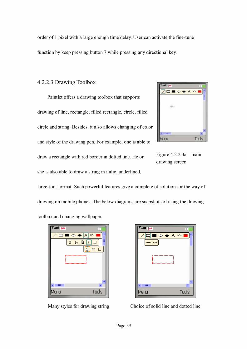
4.2.2.3 Drawing Toolbox
Paintlet offers a drawing toolbox that supports
drawing of line, rectangle, filled rectangle, circle, filled
circle and string. Besides, it also allows changing of color
and style of the drawing pen. For example, one is able to
draw a rectangle with red border in dotted line. He or
she is also able to draw a string in italic, underlined,
large-font format. Such powerful features give a complete of solution for the way of
drawing on mobile phones. The below diagrams are snapshots of using the drawing
toolbox and changing wallpaper.
Many styles for drawing string Choice of solid line and dotted line

Page 60
Figure 4.2.2.4a a pair of scroll bars
Many colors available for selection Changing of background wallpaper
Figure 4.2.2.3b diagrams showing functions of sharing white-board
4.2.2.4 Extended Screen
The actual screen size of mobile phone is so
small, which make it not be able to fully utilize
the strength of toolbox provided by Paintlet.
Dynamic point mapping algorithm has been
applied to extend the screen size to 300 x 300
square pixels now. A pairs of scroll bars are
provided to adjust the current relative screen
position with respect to original x and y coordinates correspondingly.
Clearly saying, coordinates value (s_xc, s_yc, e_xc, e_yc) of a graphic element
are of absolute while the coordinates used when presenting the graphic element is

Page 61
Figure 4.2.2.4b Idea of dynamic point mapping algorithm
calculated based on the shifting value of x scroll bar and y scroll bar and is thus
relative.
Let’s look at a further example:
The example shows that after shifting the screen with respect to x-axis of 17
pixels and y-axis of 12 pixels. The absolute coordinates (20,20) & (45,47) for
representing a line element will become (20-17,20-12) & (45-17,47-12). That is, the
new relative coordinates become (3,8) & (28,35).
Besides, the other benefit brought by this feature is that this allows defining the
absolute screen size so that it allows “100% screen synchronization”, which greatly
enhance the compatibility of the program. Let’s consider a case: If A is using a phone
with screen size of 150x200 square pixels and B is using one with screen size of
200x150 square pixels. It is not hard to imagine that there must be some areas which
Screen shifts down and right

Page 62
can be seen on local device’s side but not there on remote device’s side because their
screen areas do not fit each other.
4.2.2.5 Synchronization
There are two different synchronization mode used here. They are non-real-time
synchronization and real-time synchronization.
The first one is only used immediately after the Bluetooth establishment between
two devices to synchronize current screen and settings of both sides. There is no need
for this synchronization process to be real-time since user cannot access main screen
in this moment and thus does not see the drawing process of screen. An
acknowledgement is sent for each other if the initial synchronization is completed so
that user would enter main screen.
The second one involves the real-time synchronization used during the lifetime
of the program. It is needed here because user want the real-time effect of drawing be
shown on the screen of remote device with no delay. To achieve this, we update and
send the newest status of the Graphics elements which are being modified to remote
device for archiving real-time synchronization.
It is possible, as stated previously, because we use the signal packet architecture
to represent graphics elements so that the packet size is small enough to be sent to
Page 63
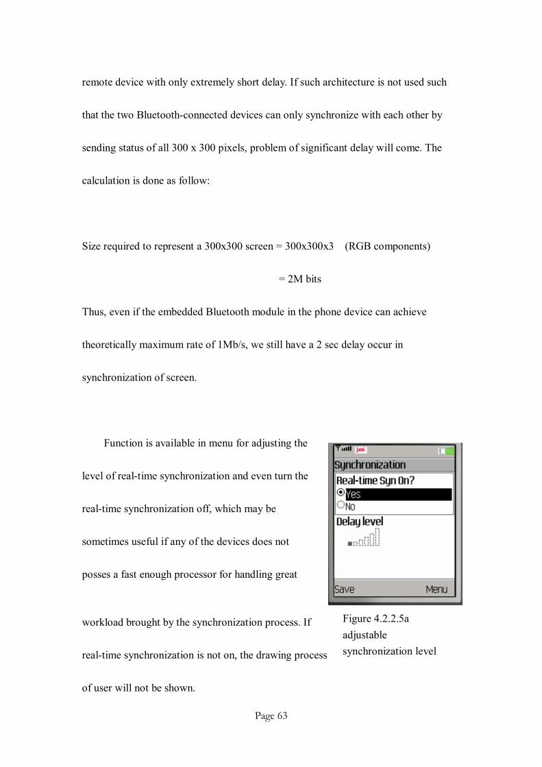
Figure 4.2.2.5a adjustable synchronization level
remote device with only extremely short delay. If such architecture is not used such
that the two Bluetooth-connected devices can only synchronize with each other by
sending status of all 300 x 300 pixels, problem of significant delay will come. The
calculation is done as follow:
Size required to represent a 300x300 screen = 300x300x3 (RGB components)
= 2M bits
Thus, even if the embedded Bluetooth module in the phone device can achieve
theoretically maximum rate of 1Mb/s, we still have a 2 sec delay occur in
synchronization of screen.
Function is available in menu for adjusting the
level of real-time synchronization and even turn the
real-time synchronization off, which may be
sometimes useful if any of the devices does not
posses a fast enough processor for handling great
workload brought by the synchronization process. If
real-time synchronization is not on, the drawing process
of user will not be shown.

Page 64
4.2.3 Voice Communication
Voice communication here refers to voice message only. In fact, real-time voice
communication is not being implemented currently and is considered as a possible
future development.
Let’s take a look at the below diagram to get an overview of the function.
Figure 4.2.3a Flow diagram of voice communication function
4.2.3.1 MMAPI
MMAPI contains a set of APIs related to multimedia functions and is defined by
JSR-135. A device not being implemented with this API does not run the voice
Page 65
communication function, though it does not cause any effect to the other 2 functions
discussed previously.
A problem has been raised during the development of voice communication
function because of the incomplete implementation of MMAPI on some models. For
example, Nokia 3230 is claimed officially to support MMAPI but it is tested that it
does not support recording and playing of *.amr audio file which is a highly
compressed audio format designed for multimedia applications such as 3G.. Similar
problems have been encountered by other developers in official Nokia forum, but
Nokia has not yet given any explanation on that.
4.2.3.2 Record and Playback
Paintlet allows recording sound of maximum 8 seconds. Such constraint is set so
as to minimize the possibility for the “Out of Memory” situation from occurring.
Audio is recorded in *.wav format since the implementation of MMAPI is not
completed on some phone models as mentioned in section 4.2.3.1. The problem of a
*.wav audio file is that the file generated is usually large in size (more than 60000
bytes for 8 seconds) which makes it impossible to transmit the whole audio file to
remote device using Bluetooth in one turn. A reliable data transfer protocol, stop &
wait protocol is used here, is needed to manage the transmission process.

Page 66
When receiver has received an audio packet sender sent, the audio packet is
combined with previously received one. The whole audio file can thus be reproduced
at the end of transmission. The audio file is automatically stored in the RMS of
Paintlet, which allows user to play the audio file at anytime and anywhere s/he wants.
4.2.3.3 Audio Transmission Protocol
Two protocols have been tested for the level of their reliability.
In protocol 1, sender splits the record wave file into small packets and
continuously sends it to receiver at a suitable rate until end of the packet. Packet(s)
will be lost in case the receiver is not able to receive and process the packet(s) fast
enough. This protocol is working based on the fact the multimedia contents are
usually loss tolerant but delay sensitive.
The other protocol is a modified version of “stop and wait” protocol
implemented on Bluetooth connection. The bellow figures describe the 5 scenarios of
this.

Page 67
Figure 4.2.2.3a normal case (1)
Figure 4.2.2.3b normal case (2)

Page 68
Figure 4.2.2.3c Case of loss packet
Figure 4.2.2.3d Case of loss acknowledgement

Page 69
Figure 4.2.2.3e Case of delayed packet
Figure 4.2.2.3f Case of delayed acknowledgement
We see that theoretically the protocol is working fine in all case. However as it is
built based on stop & wait protocol, efficiency of it is not high. After consideration of
the reliability of two protocols, protocol 2 is implemented in Paintlet to handle
transmission of audio packets.

Page 70
4.2.3.4 Best Size of an Audio Packet
Thought that most phone models support a MTU value of at least 600 bytes, it
may not be the best choice to choose 600 bytes as the size of an audio packet. It is
because an audio packet of larger size causes greater workload to receiver and
requires larger buffer to store it. Thus it may cause instability problem if “Out of
Memory” error occurs. On the contrast, a larger packet comparably generates less
overhead which reduce the size of whole audio file.
A test has been done on recording the time required to send 61644 bytes file
from a Nokia 3230 phone to Nokia 6680 phone. The result is as shown in figure
4.2.3.4a.
Figure 4.2.3.4a relationship between packet size and transmission time
The line has reached its lowest point at 18 when the packet size is 300 bytes
each. That is, the best packet size for an audio packet should be about 300 bytes each.

Page 71
The transmission rate is on average of 3424 bytes/sec.
4.2.3.5 Problems Met
We see in section 4.2.3.3 that protocol 2 is working fine and thus should have a
guaranteed reliability. However when it is tested under real phones, there is still a
possibility of having a fault during transmission on Nokia phones – sender is sending
a correct packet, but the receiver always cannot receive to the packet correctly so that
both devices hangs in a loop.
This could be due to that Nokia phone with Symbian OS 6.0 & 7.0 are found not
being able handle the operation of JSR-82 implementation very well, especially when
it comes to transmission of large packets over a Bluetooth channel. A fact that
supports this statement is that current Nokia phones are not supporting stream
connection protocol built based on JSR-82 very well such that the connection may
close automatically after a period of time.
The problem is not being able to solve with 100% guaranteed performance. It is
hoped that next version of Symbian OS supports JSR-82 in a better and more
complete way.

Page 72
Ch5 Further Development
There are mainly 2 directions for further development after consideration.
The first direction focuses on the functionality of Paintlet. For example, more
useful functions such as walkie-talkie and 3G conferences (video) may be
implemented. The second one put great importance on the multi-connections feature
of the program. Star-topology may also be implemented instead of current client &
server structure. It allows balanced workload and more efficient use of bandwidth
since no dedicated Bluetooth server is needed anymore.
Figure 5a difference between architecture of 2 protocols
A chatting program simulating the multi-connection has been written based on
client/server model structure. So far it has already run on emulators successfully.
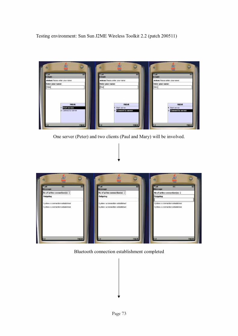
Page 73
Testing environment: Sun Sun J2ME Wireless Toolkit 2.2 (patch 200511)
One server (Peter) and two clients (Paul and Mary) will be involved.
Bluetooth connection establishment completed

Page 74
Peter is sending a message
Both Paul and Mary is able to receive the message
Figure 5b Feasibility on multi-connections Bluetooth application.

Page 75
Ch6 Conclusion
Paintlet revolutionizes the traditional way positively on how we communicate
with mobile phones. It provides a new-dimensional ways for users to exchange ideas
effectively on mobile phones by supporting practical functions such as virtual chat
room, sharing white-board and voice communication. Taking the advantages brought
by Bluetooth wireless technology, it allows a fast, reliable communication mode for
users.
With benefits of having high functionality, compatibility, flexibility and
reliability, it is believed that Paintlet will be beneficial to many mobile phones’ users.
It is hoped that there will be a further development on Paintlet so as to make it best
suit the needs of market.

Page 76
Ch7 References 1. Bluetooth for Java
Bruce Hopkins and Ranjith Antony, Apress 2 Programming Java 2Micro Edition on Symbian OS – A developer’s Guide to
MIDP 2.0 Martine de Jode, John Wiley & Sons, Ltd
3 Bluetooth Application Programming with the Java APIs C Bala Kumar, Paul J. Kline and J. Thompson, Morgan Kaufmann Publishers
4. Core J2ME Technology & MDIP
John W. Muchow, Prentice Hall PTR 5. Programming Wireless Devices with the Java 2 Platform, Micro Edition
Roger Riggs, Antero Taivalsarri, …, Addison Wesley 6. J2ME: The Complete Reference
James Keogh, McGraw-Hill 7. Java 2 Micro Edition Application Development
Michael Kroll and Stefan Haustein, Sams Publishing 8. J2ME in a Nutshell
Kim Topley, O’Reilly 9. Wireless Java Developing with J2ME, Second Edition
Jonathan Knudsen, Apress 10. Bluetooth Revealed: The Insider’s Guide to an Open Specification for Global
Wireless Communications Brent A. Miller, Chatschik Bisdikian, Ericsson Mobile Communication
11. https://www.bluetooth.org/ 12. http://forum.java.sun.com/category.jspa?categoryID=23

Page 77
13. http://www.javabluetooth.com/jsr82devices.html 14. http://wireless.klings.org/main.php/Bluetooth 15. http://www.forum.nokia.com/main/0,,150,00.html?matrixType=midp2 16. http://sourceforge.net/projects/javabluetooth 17. http://developer.sonyericsson.com/show_forums.do 18. http://www.commsdesign.com/printableArticle/?articleID=16500864 19. http://www.bluetooth.com/bluetooth/