Wind turbine icing characteristics and icing-induced BRIEF ...
8/3/2019 Demos a Icing
http://slidepdf.com/reader/full/demos-a-icing 1/5
Demosaicing with The Bayer Pattern
Rémi Jean1
Department of Computer Science,
University of North Carolina
Abstract
Digital cameras are becoming more and more
powerful but even if they are smaller, the CCD sensors
still associate only one color to each pixel. This mosaic of
color, called The Bayer Pattern, must be processed in order
to obtain a high resolution color image. Each pixel of this
interpolated image has a full spectrum of color based on
the colors of the surrounding pixels. This process isreferred as demosaicing or demosaicking. This report
presents the work I have done for the final project, which
was to implement and compare different commonly used
demosaicing methods.
1 Introduction
The resolutions for digital cameras are becoming
bigger and bigger but the principle is still the same. These
cameras are based on a charge coupled device (CCD) array
and each sensor on the CCD captures only one sample of
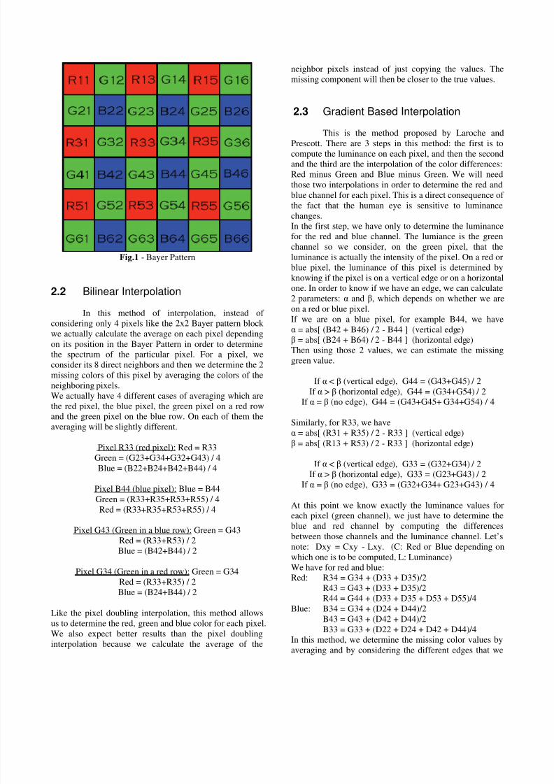
the color spectrum.Digital color cameras generally use a Bayer mask
over the CCD. A Bayer filter mosaic is a color filter array
(CFA) for arranging Red Green Blue (RGB) color filters
on a square grid of photosensors. [Fig. 1] Each square of
four pixels has one filtered red, one blue, and two green.
This is because the human eye is more sensitive to green
than either red or blue.
We now have a mosaiced image; at each pixel,
there is only one spectral measurement, which means that
the other colors have to be estimated according to the
neighboring colors in order to produce a high resolution
color image. This process is referred to as demosaicing.
The mosaiced image is the first image, we now will haveto perform interpolations on this image. There are many
different methods to do this, of which i am going to
present four and compare them according to a similarity
measurement: the Peak Signal to Noise Ratio (PSNR) in
dB. I will present first a nearest neighbor interpolation and
then several other methods that involves averaging such as
a bilinear interpolation, a Fast High Quality Linear
_______________________
1. e-mail: [email protected]
Interpolation and a Gradient based interpolation. The
comparison of the different algorithms is based on an
image by Kodak. It provides an excellent cross-section of
environments and also demosaicing "trouble-spots", such
as fine details and picket fences.
2 Demosaicing methods
2.1 Pixel Doubling Interpolation
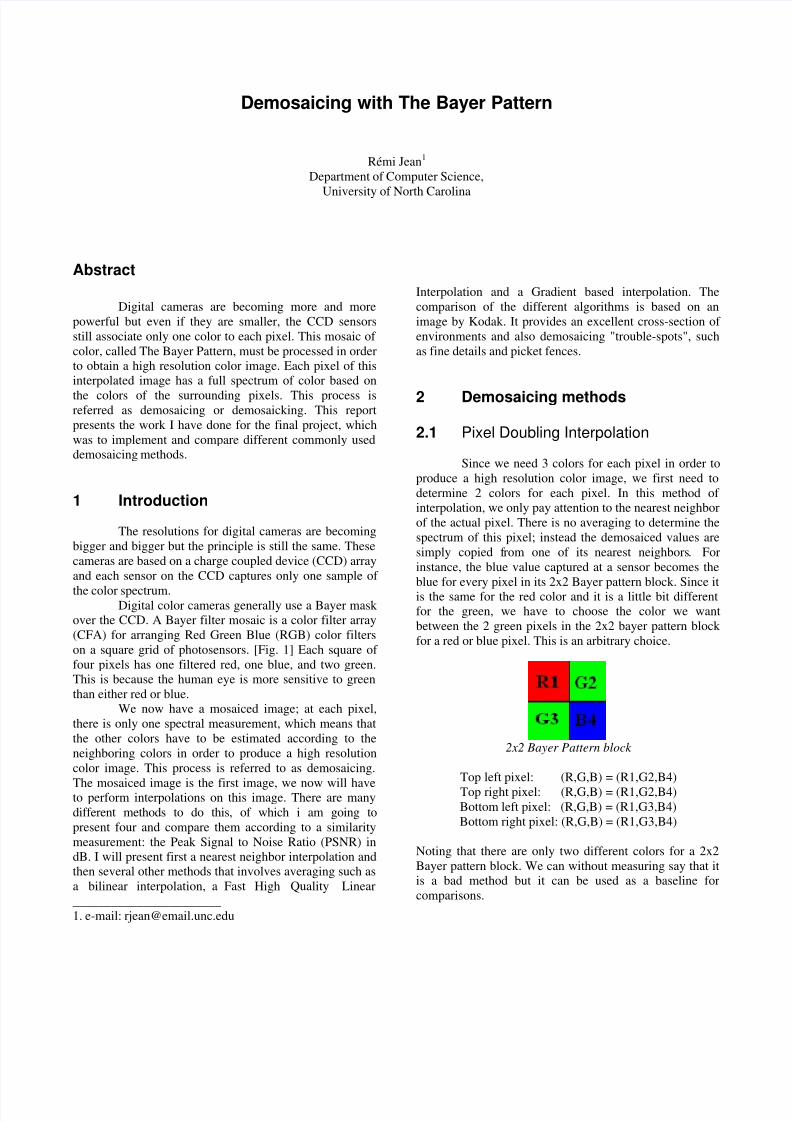
Since we need 3 colors for each pixel in order to
produce a high resolution color image, we first need to
determine 2 colors for each pixel. In this method of
interpolation, we only pay attention to the nearest neighbor
of the actual pixel. There is no averaging to determine the
spectrum of this pixel; instead the demosaiced values are
simply copied from one of its nearest neighbors. For
instance, the blue value captured at a sensor becomes the
blue for every pixel in its 2x2 Bayer pattern block. Since it
is the same for the red color and it is a little bit different
for the green, we have to choose the color we want
between the 2 green pixels in the 2x2 bayer pattern block
for a red or blue pixel. This is an arbitrary choice.
2x2 Bayer Pattern block
Top left pixel: (R,G,B) = (R1,G2,B4)
Top right pixel: (R,G,B) = (R1,G2,B4)
Bottom left pixel: (R,G,B) = (R1,G3,B4)
Bottom right pixel: (R,G,B) = (R1,G3,B4)
Noting that there are only two different colors for a 2x2
Bayer pattern block. We can without measuring say that it
is a bad method but it can be used as a baseline for
comparisons.
8/3/2019 Demos a Icing
http://slidepdf.com/reader/full/demos-a-icing 2/5
Fig.1 - Bayer Pattern
2.2 Bilinear Interpolation
In this method of interpolation, instead of
considering only 4 pixels like the 2x2 Bayer pattern block
we actually calculate the average on each pixel depending
on its position in the Bayer Pattern in order to determine
the spectrum of the particular pixel. For a pixel, we
consider its 8 direct neighbors and then we determine the 2
missing colors of this pixel by averaging the colors of the
neighboring pixels.
We actually have 4 different cases of averaging which are
the red pixel, the blue pixel, the green pixel on a red row
and the green pixel on the blue row. On each of them the
averaging will be slightly different.
Pixel R33 (red pixel): Red = R33
Green = (G23+G34+G32+G43) / 4
Blue = (B22+B24+B42+B44) / 4
Pixel B44 (blue pixel): Blue = B44
Green = (R33+R35+R53+R55) / 4
Red = (R33+R35+R53+R55) / 4
Pixel G43 (Green in a blue row): Green = G43
Red = (R33+R53) / 2
Blue = (B42+B44) / 2
Pixel G34 (Green in a red row): Green = G34
Red = (R33+R35) / 2
Blue = (B24+B44) / 2
Like the pixel doubling interpolation, this method allows
us to determine the red, green and blue color for each pixel.
We also expect better results than the pixel doubling
interpolation because we calculate the average of the
neighbor pixels instead of just copying the values. The
missing component will then be closer to the true values.
2.3 Gradient Based Interpolation
This is the method proposed by Laroche andPrescott. There are 3 steps in this method: the first is to
compute the luminance on each pixel, and then the second
and the third are the interpolation of the color differences:
Red minus Green and Blue minus Green. We will need
those two interpolations in order to determine the red and
blue channel for each pixel. This is a direct consequence of
the fact that the human eye is sensitive to luminance
changes.
In the first step, we have only to determine the luminance
for the red and blue channel. The lumiance is the green
channel so we consider, on the green pixel, that the
luminance is actually the intensity of the pixel. On a red or
blue pixel, the luminance of this pixel is determined by
knowing if the pixel is on a vertical edge or on a horizontalone. In order to know if we have an edge, we can calculate
2 parameters: α and β, which depends on whether we are
on a red or blue pixel.
If we are on a blue pixel, for example B44, we have
α = abs[ (B42 + B46) / 2 - B44 ] (vertical edge)β = abs[ (B24 + B64) / 2 - B44 ] (horizontal edge)
Then using those 2 values, we can estimate the missing
green value.
If α < β (vertical edge), G44 = (G43+G45) / 2
If α > β (horizontal edge), G44 = (G34+G54) / 2
If α = β (no edge), G44 = (G43+G45+ G34+G54) / 4
Similarly, for R33, we have
α = abs[ (R31 + R35) / 2 - R33 ] (vertical edge)
β = abs[ (R13 + R53) / 2 - R33 ] (horizontal edge)
If α < β (vertical edge), G33 = (G32+G34) / 2
If α > β (horizontal edge), G33 = (G23+G43) / 2
If α = β (no edge), G33 = (G32+G34+ G23+G43) / 4
At this point we know exactly the luminance values for
each pixel (green channel), we just have to determine the
blue and red channel by computing the differences
between those channels and the luminance channel. Let’s
note: Dxy = Cxy - Lxy. (C: Red or Blue depending onwhich one is to be computed, L: Luminance)
We have for red and blue:
Red: R34 = G34 + (D33 + D35)/2
R43 = G43 + (D33 + D35)/2
R44 = G44 + (D33 + D35 + D53 + D55)/4
Blue: B34 = G34 + (D24 + D44)/2
B43 = G43 + (D42 + D44)/2
B33 = G33 + (D22 + D24 + D42 + D44)/4
In this method, we determine the missing color values by
averaging and by considering the different edges that we
8/3/2019 Demos a Icing
http://slidepdf.com/reader/full/demos-a-icing 3/5
encounter in the image and also by computing the
luminance. We can expect to have more accurate colors in
output especially on the edges. When we find an edge, we
consider the pixels along the edge instead of considering
all the neighbors.
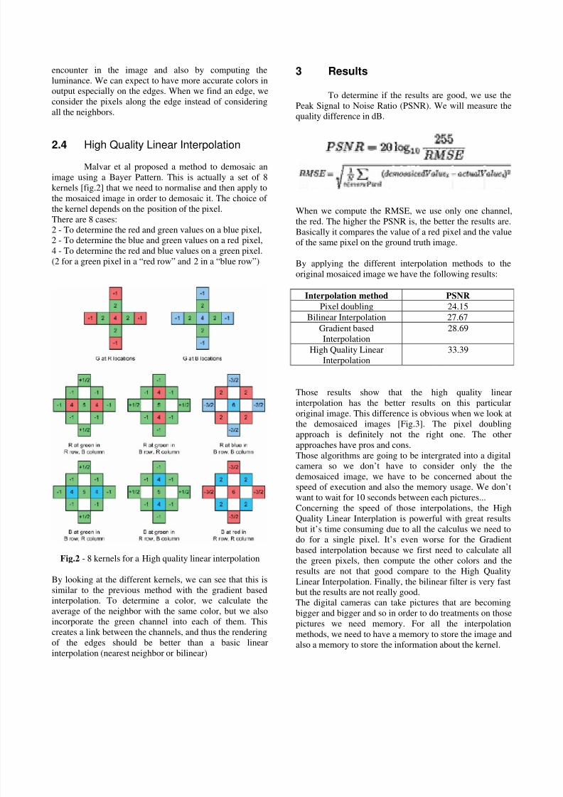
2.4 High Quality Linear Interpolation
Malvar et al proposed a method to demosaic an
image using a Bayer Pattern. This is actually a set of 8
kernels [fig.2] that we need to normalise and then apply to
the mosaiced image in order to demosaic it. The choice of
the kernel depends on the position of the pixel.
There are 8 cases:
2 - To determine the red and green values on a blue pixel,
2 - To determine the blue and green values on a red pixel,
4 - To determine the red and blue values on a green pixel.
(2 for a green pixel in a “red row” and 2 in a “blue row”)
Fig.2 - 8 kernels for a High quality linear interpolation
By looking at the different kernels, we can see that this is
similar to the previous method with the gradient based
interpolation. To determine a color, we calculate the
average of the neighbor with the same color, but we also
incorporate the green channel into each of them. This
creates a link between the channels, and thus the rendering
of the edges should be better than a basic linear
interpolation (nearest neighbor or bilinear)
3 Results
To determine if the results are good, we use the
Peak Signal to Noise Ratio (PSNR). We will measure the
quality difference in dB.
When we compute the RMSE, we use only one channel,
the red. The higher the PSNR is, the better the results are.
Basically it compares the value of a red pixel and the value
of the same pixel on the ground truth image.
By applying the different interpolation methods to the
original mosaiced image we have the following results:
Interpolation method PSNR
Pixel doubling 24.15
Bilinear Interpolation 27.67
Gradient based
Interpolation
28.69
High Quality Linear
Interpolation
33.39
Those results show that the high quality linear
interpolation has the better results on this particular
original image. This difference is obvious when we look at
the demosaiced images [Fig.3]. The pixel doubling
approach is definitely not the right one. The other
approaches have pros and cons.
Those algorithms are going to be intergrated into a digital
camera so we don’t have to consider only the the
demosaiced image, we have to be concerned about the
speed of execution and also the memory usage. We don’t
want to wait for 10 seconds between each pictures...
Concerning the speed of those interpolations, the High
Quality Linear Interplation is powerful with great results
but it’s time consuming due to all the calculus we need to
do for a single pixel. It’s even worse for the Gradient
based interpolation because we first need to calculate all
the green pixels, then compute the other colors and theresults are not that good compare to the High Quality
Linear Interpolation. Finally, the bilinear filter is very fast
but the results are not really good.
The digital cameras can take pictures that are becoming
bigger and bigger and so in order to do treatments on those
pictures we need memory. For all the interpolation
methods, we need to have a memory to store the image and
also a memory to store the information about the kernel.
8/3/2019 Demos a Icing
http://slidepdf.com/reader/full/demos-a-icing 4/5
All those interpolations are similar concerning the memory
usage, the only difference between those interpolations
about the memory is the space they need to store the
kernels. For the bilinear and the gradient based
interpolation, they almost do not need any additionnal
memory because it’s only some small calculus. The high
quality linear interpolation need a bit more storage because
it needs to store the 8 kernels in addition to the memory
needed for the calculus.
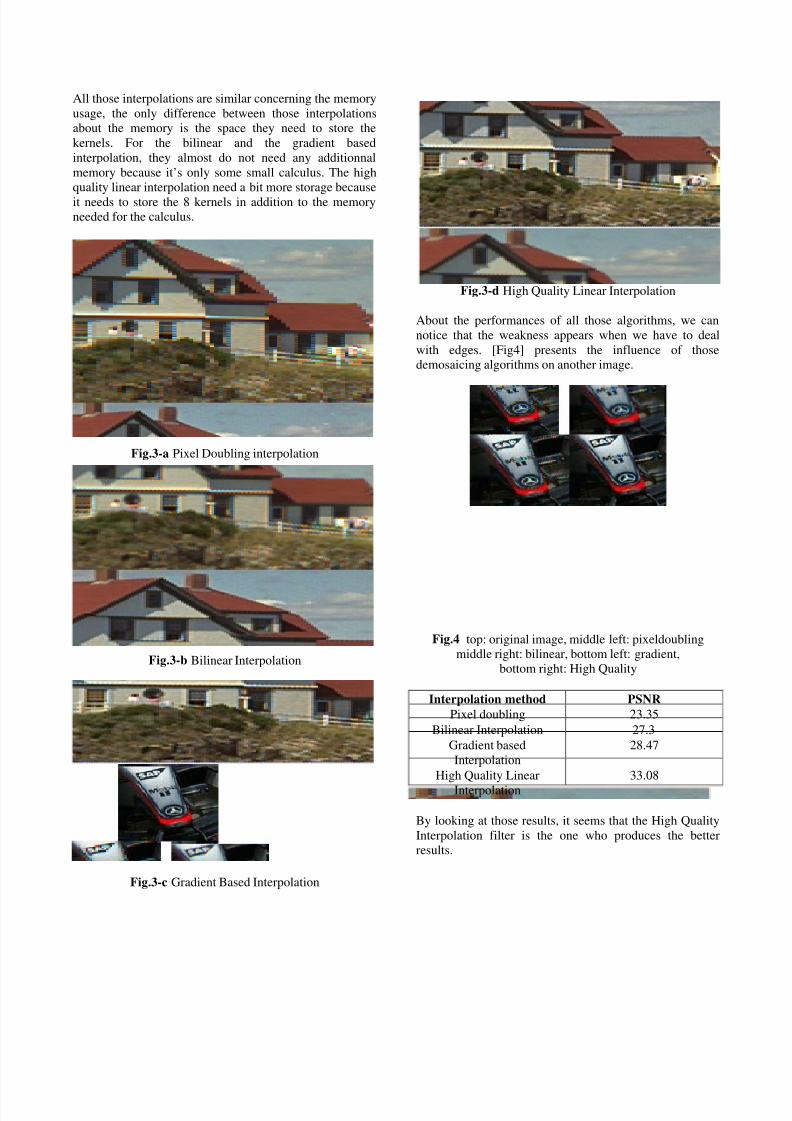
Fig.3-a Pixel Doubling interpolation
Fig.3-b Bilinear Interpolation
Fig.3-c Gradient Based Interpolation
Fig.3-d High Quality Linear Interpolation
About the performances of all those algorithms, we can
notice that the weakness appears when we have to deal
with edges. [Fig4] presents the influence of those
demosaicing algorithms on another image.
Fig.4 top: original image, middle left: pixeldoubling
middle right: bilinear, bottom left: gradient,
bottom right: High Quality
Interpolation method PSNR
Pixel doubling 23.35
Bilinear Interpolation 27.3
Gradient based
Interpolation
28.47
High Quality Linear
Interpolation
33.08
By looking at those results, it seems that the High Quality
Interpolation filter is the one who produces the better
results.
8/3/2019 Demos a Icing
http://slidepdf.com/reader/full/demos-a-icing 5/5
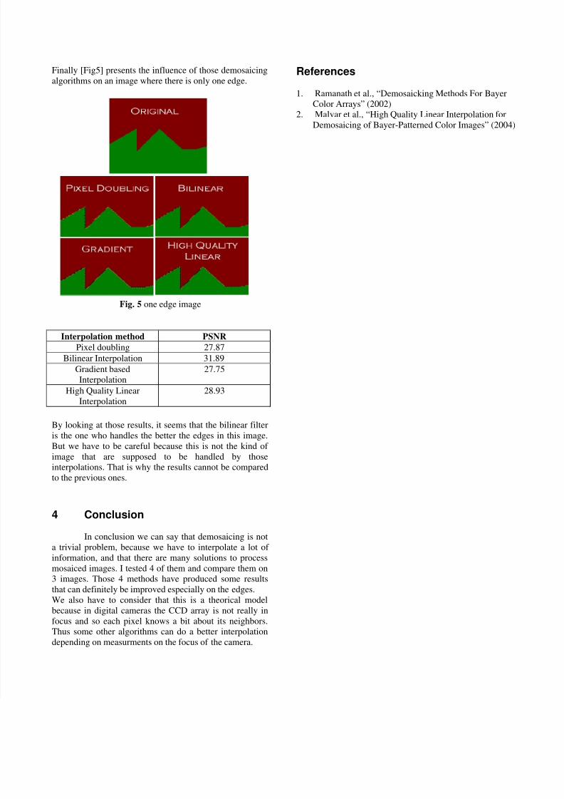
Finally [Fig5] presents the influence of those demosaicing
algorithms on an image where there is only one edge.
Fig. 5 one edge image
Interpolation method PSNR
Pixel doubling 27.87
Bilinear Interpolation 31.89
Gradient based
Interpolation
27.75
High Quality Linear
Interpolation
28.93
By looking at those results, it seems that the bilinear filter
is the one who handles the better the edges in this image.
But we have to be careful because this is not the kind of
image that are supposed to be handled by those
interpolations. That is why the results cannot be compared
to the previous ones.
4 Conclusion
In conclusion we can say that demosaicing is not
a trivial problem, because we have to interpolate a lot of
information, and that there are many solutions to processmosaiced images. I tested 4 of them and compare them on
3 images. Those 4 methods have produced some results
that can definitely be improved especially on the edges.
We also have to consider that this is a theorical model
because in digital cameras the CCD array is not really in
focus and so each pixel knows a bit about its neighbors.
Thus some other algorithms can do a better interpolation
depending on measurments on the focus of the camera.
References
1. Ramanath et al., “Demosaicking Methods For Bayer
Color Arrays” (2002)
2. Malvar et al., “High Quality Linear Interpolation for
Demosaicing of Bayer-Patterned Color Images” (2004)