Aircraft anti icing & de-icing sytems project report
52
Anti-icing & de-icing systems ASSESSORS NAME: MR. ANAND NAIR EAC0812445, EAC0812431, EAC0912496 EMIRATES AVIATION UNVERSITY 23-Jun-14 By: FRANCIS, KHAWAR, & ERANGA
-
Upload
-eranga-jr-abw -
Category
Engineering
-
view
152 -
download
13
Transcript of Aircraft anti icing & de-icing sytems project report
Anti-icing & de-icing systems
A S S E S S O R S N A M E : M R . A N A N D N A I R
E A C 0 8 1 2 4 4 5 , E A C 0 8 1 2 4 3 1 , E A C 0 9 1 2 4 9 6
E M I R A T E S A V I A T I O N U N V E R S I T Y
2 3 - J u n - 1 4
By: FRANCIS, KHAWAR, & ERANGA
Page 1 of 52 FRANCIS, ERANGA, KHAWAR PROJECT REPORT FOR AIRCRAFT ANTI-ICING AND DEICING SYSTEMS
Table of Contents Introduction ............................................................................................................................................ 3
History of Anti-Icing & De-Icing Systems: ................................................................................................ 4
A Few Types of Systems: ......................................................................................................................... 6
- Pneumatic deicing boots:...................................................................................................... 6
- Electric thermal: .................................................................................................................. 6
- Bleed air: ............................................................................................................................... 7
- Electro-mechanical: ............................................................................................................ 7
- Weeping wing: ..................................................................................................................... 7
Theory of operation: ............................................................................................................................... 9
1. Windshield: ..................................................................................................................................... 9
2. Pitot Tube ..................................................................................................................................... 11
3. Leading Edge/Airfoil: .................................................................................................................... 16
Types of Ice Detectors: ............................................................................................................................. 21
1. Pressure Operated Ice Detector Head: .......................................................................................... 21
2. Serrated Rotor Ice Detector Head: ................................................................................................ 21
3. Vibrating Rod Ice Detector Head: .................................................................................................. 22
Design concept of the model: .................................................................................................................... 23
Survey: .................................................................................................................................................. 23
1. Windshield: ................................................................................................................................... 23
2. Pitot Tube: .................................................................................................................................... 24
3. Airfoil: ........................................................................................................................................... 25
Budget: ................................................................................................................................................. 26
Initial Sketch / Final Sketch: .................................................................................................................. 28
1. Pitot tube: ..................................................................................................................................... 28
2. Windshield: ................................................................................................................................... 29
3. Leading Edge / Airfoil: ................................................................................................................... 31
Construction of the model .................................................................................................................... 33
Materials Required: .............................................................................................................................. 33
1. Airfoil: ................................................................................................................................... 33
2. Windshield: ........................................................................................................................... 33
3. Pitot tube: ............................................................................................................................. 33
Page 2 of 52 FRANCIS, ERANGA, KHAWAR PROJECT REPORT FOR AIRCRAFT ANTI-ICING AND DEICING SYSTEMS
Tools required and their use: ................................................................................................................ 34
Step by Step Procedure with dimensions & pictures: ........................................................................... 35
1. Pitot Tube: .................................................................................................................................... 35
2. Windshield: ................................................................................................................................... 36
3. Leading Edge: ................................................................................................................................ 37
Safety Precautions: ............................................................................................................................... 43
Operation Manual: ............................................................................................................................... 43
Problems Faced: ................................................................................................................................... 45
1. Airfoil: ........................................................................................................................................... 45
2. Pitot tube: ..................................................................................................................................... 45
3. Windshield: ................................................................................................................................... 45
Risk Assessment: .................................................................................................................................. 46
1. Airfoil: ........................................................................................................................................... 46
2. Pitot tube: ..................................................................................................................................... 47
3. Windshield: ................................................................................................................................... 48
Future Improvements: .......................................................................................................................... 49
1. Airfoil: ........................................................................................................................................... 49
2. Pitot tube: ..................................................................................................................................... 49
3. Windshield: ................................................................................................................................... 49
Conclusion ............................................................................................................................................ 50
Reference ............................................................................................................................................. 51
Picture References ................................................................................................................................ 51
Page 3 of 52 FRANCIS, ERANGA, KHAWAR PROJECT REPORT FOR AIRCRAFT ANTI-ICING AND DEICING SYSTEMS
Introduction
In the new modern era anti-icing and de-icing systems are most important to the
aircrafts performance, efficiency and quality but most importantly their future. Without
anti-icing and de-icing systems aircrafts would have a difficulty with communication,
speed, altitude, vision, and structure.
There are two types of Ice removal:-
1. Anti-icing:
Preventive and turned on before the flight enters icing conditions or kept on in most
aircrafts (Specially the Pitot tube and static vent). This includes: thermal heat, prop heat,
Pitot heat, fuel vent heat, windshield heat, and fluid surface de-icers.
2. De-icing:
This is very reactive, used after there has been significant ice buildup. This includes:
surface de-ice equipment such as boots, weeping wing systems, and heated wings.
A few effects:
- Once ice is formed on the wing airfoil, the shape is changed which causes the
airfoils use less effective. This intentionally lowers the aircrafts streamline flow
around the leading edges.
- Much more drag is created causing loss of lift. The ice can cause skin friction
leading to small tears in the structure.
- Ice formation on the engine blades changes its shape making it less effective and
efficient.
Page 4 of 52 FRANCIS, ERANGA, KHAWAR PROJECT REPORT FOR AIRCRAFT ANTI-ICING AND DEICING SYSTEMS
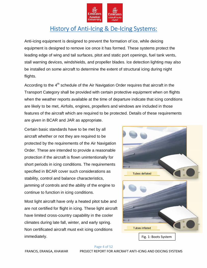
Fig. 1: Boots System
History of Anti-Icing & De-Icing Systems:
Anti-icing equipment is designed to prevent the formation of ice, while deicing
equipment is designed to remove ice once it has formed. These systems protect the
leading edge of wing and tail surfaces, pitot and static port openings, fuel tank vents,
stall warning devices, windshields, and propeller blades. Ice detection lighting may also
be installed on some aircraft to determine the extent of structural icing during night
flights.
According to the 4th schedule of the Air Navigation Order requires that aircraft in the
Transport Category shall be provided with certain protective equipment when on flights
when the weather reports available at the time of departure indicate that icing conditions
are likely to be met, Airfoils, engines, propellers and windows are included in those
features of the aircraft which are required to be protected. Details of these requirements
are given in BCAR and JAR as appropriate.
Certain basic standards have to be met by all
aircraft whether or not they are required to be
protected by the requirements of the Air Navigation
Order. These are intended to provide a reasonable
protection if the aircraft is flown unintentionally for
short periods in icing conditions. The requirements
specified in BCAR cover such considerations as
stability, control and balance characteristics,
jamming of controls and the ability of the engine to
continue to function in icing conditions.
Most light aircraft have only a heated pitot tube and
are not certified for flight in icing. These light aircraft
have limited cross-country capability in the cooler
climates during late fall, winter, and early spring.
Non certificated aircraft must exit icing conditions
immediately.
Page 5 of 52 FRANCIS, ERANGA, KHAWAR PROJECT REPORT FOR AIRCRAFT ANTI-ICING AND DEICING SYSTEMS
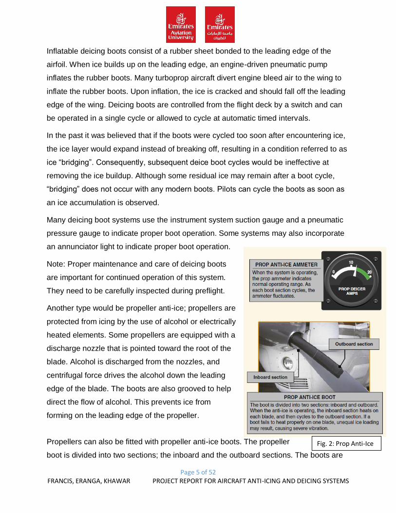
Fig. 2: Prop Anti-Ice
Inflatable deicing boots consist of a rubber sheet bonded to the leading edge of the
airfoil. When ice builds up on the leading edge, an engine-driven pneumatic pump
inflates the rubber boots. Many turboprop aircraft divert engine bleed air to the wing to
inflate the rubber boots. Upon inflation, the ice is cracked and should fall off the leading
edge of the wing. Deicing boots are controlled from the flight deck by a switch and can
be operated in a single cycle or allowed to cycle at automatic timed intervals.
In the past it was believed that if the boots were cycled too soon after encountering ice,
the ice layer would expand instead of breaking off, resulting in a condition referred to as
ice “bridging”. Consequently, subsequent deice boot cycles would be ineffective at
removing the ice buildup. Although some residual ice may remain after a boot cycle,
“bridging” does not occur with any modern boots. Pilots can cycle the boots as soon as
an ice accumulation is observed.
Many deicing boot systems use the instrument system suction gauge and a pneumatic
pressure gauge to indicate proper boot operation. Some systems may also incorporate
an annunciator light to indicate proper boot operation.
Note: Proper maintenance and care of deicing boots
are important for continued operation of this system.
They need to be carefully inspected during preflight.
Another type would be propeller anti-ice; propellers are
protected from icing by the use of alcohol or electrically
heated elements. Some propellers are equipped with a
discharge nozzle that is pointed toward the root of the
blade. Alcohol is discharged from the nozzles, and
centrifugal force drives the alcohol down the leading
edge of the blade. The boots are also grooved to help
direct the flow of alcohol. This prevents ice from
forming on the leading edge of the propeller.
Propellers can also be fitted with propeller anti-ice boots. The propeller
boot is divided into two sections; the inboard and the outboard sections. The boots are
Page 6 of 52 FRANCIS, ERANGA, KHAWAR PROJECT REPORT FOR AIRCRAFT ANTI-ICING AND DEICING SYSTEMS
imbedded with electrical wires that carry current for heating the propeller. The prop anti-
ice system can be monitored for proper operation by monitoring the prop anti-ice
ammeter. During the preflight inspection, check the propeller boots for proper operation.
If a boot fails to heat one blade, an unequal blade loading can result, and may cause
severe propeller vibration.
- Other Anti-ice and Deice Systems:
Pitot and static ports, fuel vents, stall warning sensors, and other optional equipment
may be heated by electrical elements.
Operation of aircraft anti-icing and deicing systems should be checked prior to
encountering icing conditions. Encounters with structural ice require immediate action.
Anti-icing and deicing equipment are not intended to sustain long term flight in icing
conditions.
A Few Types of Systems:
- Pneumatic deicing boots:
The pneumatic boot is a rubber device attached to a wing's leading edge, invented by
the Goodrich Corporation (previously known as B.F. Goodrich) in 1923. Portions of the
boot are alternately inflated and deflated to break ice off the boot, de-icing the wing.
Rubber boots are used on jets and propeller driven aircraft.
- Electric thermal:
The Thermawing is an electrical ice protection system for general aviation. ThermaWing
uses a flexible, electrically conductive, graphite foil attached to a wing's leading edge.
Electric heaters heat the foil and melt the ice.
A new proposal uses special soot made of carbon nanotubes. A thin filament is spun on
a winder to create a 10 micron-thick film, equivalent to an A4 sheet of paper. The film is
a poor conductor of electricity, because of the air gaps between the nanotubes. Instead,
current manifests as a near instantaneous rise in temperature. It heats up twice as fast
as nichrome, the heating element of choice for in-flight de-icing, using half as much
energy at one ten-thousandth the weight. The amount of material needed to cover the
Page 7 of 52 FRANCIS, ERANGA, KHAWAR PROJECT REPORT FOR AIRCRAFT ANTI-ICING AND DEICING SYSTEMS
wings of a jumbo jet weighs 80 grams (2.8 Oz). The material cost is approximately 1%
of nichrome. Aerogel heaters could be left on continuously at low power, to prevent ice
from forming.
- Bleed air:
A bleed air system is used by larger jet aircraft to keep flight surfaces above the
freezing temperature required for ice to accumulate (called anti-icing). The hot air is
"bled" off the jet engine into tubes routed through wings, tail surfaces, and engine inlets.
- Electro-mechanical:
Electro-mechanical Expulsion Deicing Systems (EMEDS) use a mechanical force to
knock the ice off the flight surface. Typically, actuators are installed underneath the skin
of the structure. The actuator is moved to induce a shock wave in the protected surface
to dislodge the ice. Cox and Company, Inc. of Plainview, NY developed a lightweight;
low-power system called EMEDS that is the first ice protection technology to receive
FAA certification in 50 years, and is currently in-service on multiple commercial aircraft
(FAA Part 23 and Part 25) and military aircraft.
Innovative Dynamics has developed a lightweight and low-power system using
actuators, called EIDI.
Hybrid Electro-Mechanical Expulsion Deicing Systems combine an EMEDS de-icer with
an electrical heating element anti-icer. The heater prevents ice accumulation on the
leading edge of the airfoil and the actuators of the EMED system remove ice that
accumulates aft of the heated portion of the airfoil Cox and Company, Inc. of Plainview,
NY has developed multiple versions of Hybrid EMED systems referred to as Thermo-
Mechanical Expulsion Deicing System (TMEDS).
- Weeping wing:
A weeping wing system, also known as a TKS (Tecalemit-Kilfrost-Sheepbridge Stokes)
system, uses a liquid based on ethylene glycol to coat the wing surface and prevent ice
from accumulating. The leading edges of the wings, horizontal and vertical stabilizer are
made of porous, laser-drilled titanium panels, through which the fluid is pumped during
flight in icing conditions. A "slinger ring" may be used to distribute fluid on propellers,

Page 8 of 52 FRANCIS, ERANGA, KHAWAR PROJECT REPORT FOR AIRCRAFT ANTI-ICING AND DEICING SYSTEMS
and a spray bar can be used to apply fluid to the windshield. This system is commonly
used on small-to-medium-sized propeller-driven aircraft, and a number of business jet
aircraft. It also has some military application.
Page 9 of 52 FRANCIS, ERANGA, KHAWAR PROJECT REPORT FOR AIRCRAFT ANTI-ICING AND DEICING SYSTEMS
Theory of operation:
1. Windshield:
- Basic operation:
Windshield protection plays a very important role in the aircrafts structure as we can
protect it from blur ness, formation of ice on the windshield by using anti-icing systems.
As for our model we have planned to use electrical heating strips to prevent formation of
ice on the windshield; hence in many aircrafts there are other systems such,
- Fluid system:
As for our model of windshield we are using electrical heating system, the heating strips
will be sandwiched between the glasses and its terminals are connected to a battery
supply that being our power source.
- History:
The windshield anti-icing and defogging system keeps the windshield and side windows
clear in ice or fog conditions. The system has two sub-systems, left hand and right
hand, which operate independently. Each sub-system supplies heat to two side
windows (one sliding and one fixed) and one windshield.
Each window has two temperature sensors, one controls the temperature the other is
spare. The windshield has three temperature sensors, one controls the temperature the
other two are spare.
The sensors control the temperature between 35°C (95°F) and 42°C (107.6°F).
The windshield anti-icing and defogging system is automatically energized when the
first engine starts. The PROBES/WINDOW HEAT P/BSW, on the overhead panel
25VU, can be pushed in (on) if the system is necessary before engine start.
Page 10 of 52 FRANCIS, ERANGA, KHAWAR PROJECT REPORT FOR AIRCRAFT ANTI-ICING AND DEICING SYSTEMS
- Project Model:
For this model we bought 2 car windows glasses which will be used as an aircraft’s
windshield. The 2 glasses will be sandwiched using a wooden frame. The main idea is
to heat the glasses without causing any cracks or any F.O.D. The heating elements will
be suspended in air in between the sandwiched glass. This heat will cause the ice to
melt and not to form as well. The heating strips cool off easily as well as heats very
quickly which is good for maintenance. Quick maintenance. Profitable in aviation.
Types of components:
- Heating Strips: These will be used to provide heat to the wind shield so the ice
formation can be avoided. This works basically by providing heat to the glass
from behind which spread to the surface of the windshield.
- Heating Wire: These are used to hold the heat. It will be connected to a power
supply will be toggled by a switch.
- Light Indicators: This is used to show that the system is in function mode (Green)
and (Red) showing that the system isn’t functioning or switched off.
- Switch: This components is the key to switch on/off the system.
- Battery: This is the main power supply which produces 12V of power.
Page 11 of 52 FRANCIS, ERANGA, KHAWAR PROJECT REPORT FOR AIRCRAFT ANTI-ICING AND DEICING SYSTEMS
2. Pitot Tube:
As we know that the Pitot tube is a very important component for an aircraft. As it shows
the aircrafts speed, altitude, and VSI. To protect this component we use an anti-icing
system, which will be switched on all the time during flights basically to avoid the
formation of ice.
- History:
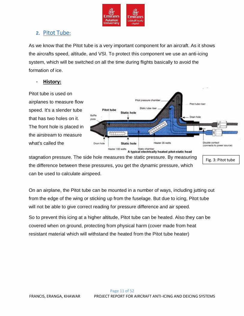
Pitot tube is used on
airplanes to measure flow
speed. It's a slender tube
that has two holes on it.
The front hole is placed in
the airstream to measure
what's called the
stagnation pressure. The side hole measures the static pressure. By measuring
the difference between these pressures, you get the dynamic pressure, which
can be used to calculate airspeed.
On an airplane, the Pitot tube can be mounted in a number of ways, including jutting out
from the edge of the wing or sticking up from the fuselage. But due to icing, Pitot tube
will not be able to give correct reading for pressure difference and air speed.
So to prevent this icing at a higher altitude, Pitot tube can be heated. Also they can be
covered when on ground, protecting from physical harm (cover made from heat
resistant material which will withstand the heated from the Pitot tube heater)
Fig. 3: Pitot tube
Page 12 of 52 FRANCIS, ERANGA, KHAWAR PROJECT REPORT FOR AIRCRAFT ANTI-ICING AND DEICING SYSTEMS
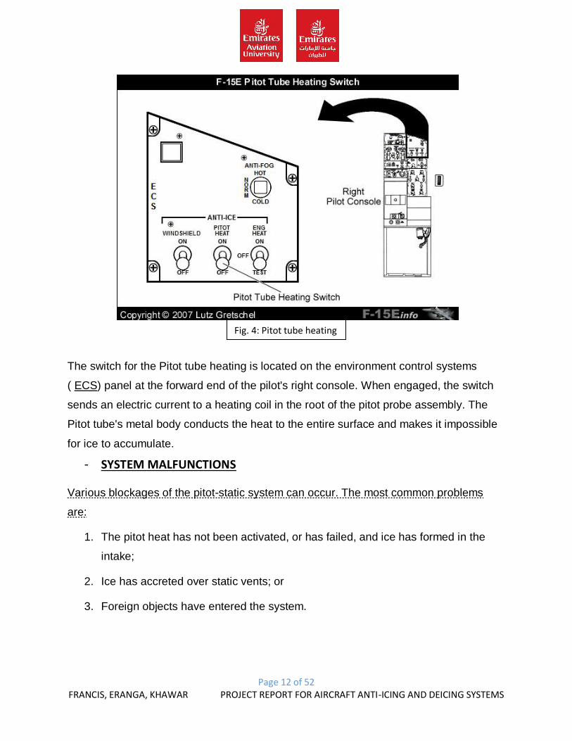
The switch for the Pitot tube heating is located on the environment control systems
( ECS) panel at the forward end of the pilot's right console. When engaged, the switch
sends an electric current to a heating coil in the root of the pitot probe assembly. The
Pitot tube's metal body conducts the heat to the entire surface and makes it impossible
for ice to accumulate.
- SYSTEM MALFUNCTIONS
Various blockages of the pitot-static system can occur. The most common problems
are:
1. The pitot heat has not been activated, or has failed, and ice has formed in the
intake;
2. Ice has accreted over static vents; or
3. Foreign objects have entered the system.
Fig. 4: Pitot tube heating
switch
Page 13 of 52 FRANCIS, ERANGA, KHAWAR PROJECT REPORT FOR AIRCRAFT ANTI-ICING AND DEICING SYSTEMS
Fig. 5: Blockage Category
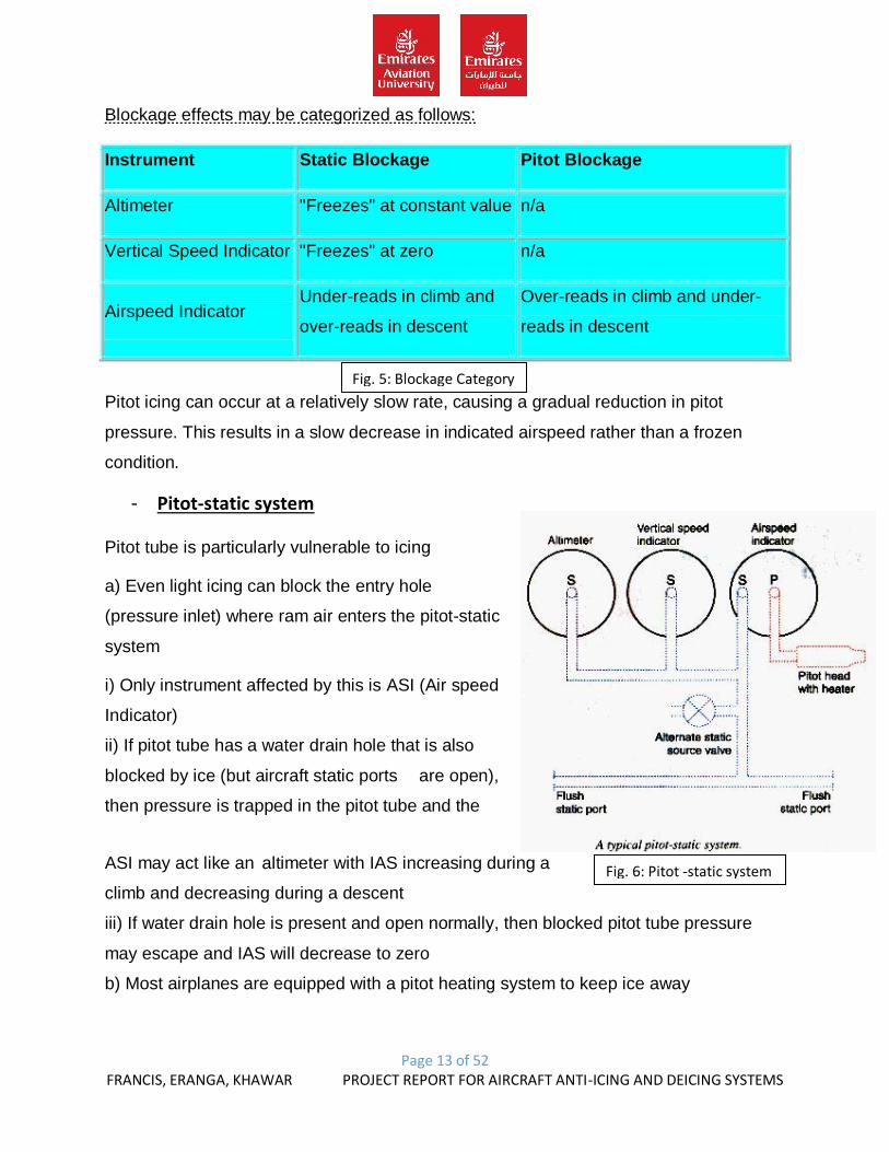
Fig. 6: Pitot -static system
Blockage effects may be categorized as follows:
Instrument Static Blockage Pitot Blockage
Altimeter "Freezes" at constant value n/a
Vertical Speed Indicator "Freezes" at zero n/a
Airspeed Indicator Under-reads in climb and
over-reads in descent
Over-reads in climb and under-
reads in descent
Pitot icing can occur at a relatively slow rate, causing a gradual reduction in pitot
pressure. This results in a slow decrease in indicated airspeed rather than a frozen
condition.
- Pitot-static system
Pitot tube is particularly vulnerable to icing
a) Even light icing can block the entry hole
(pressure inlet) where ram air enters the pitot-static
system
i) Only instrument affected by this is ASI (Air speed
Indicator)
ii) If pitot tube has a water drain hole that is also
blocked by ice (but aircraft static ports are open),
then pressure is trapped in the pitot tube and the
ASI may act like an altimeter with IAS increasing during a
climb and decreasing during a descent
iii) If water drain hole is present and open normally, then blocked pitot tube pressure
may escape and IAS will decrease to zero
b) Most airplanes are equipped with a pitot heating system to keep ice away
Page 14 of 52 FRANCIS, ERANGA, KHAWAR PROJECT REPORT FOR AIRCRAFT ANTI-ICING AND DEICING SYSTEMS
i) Usually consists of coiled wire heating element wrapped around the air entry tube
ii) Apply pitot heat before entering an area of suspected icing
iii) Beware of potentially significant current drain of pitot heater
Cessna TR-182
i) Pitot heat system consists of heating element in Pitot tube, rocker PITOT HEAT
switch, 10-amp push-to-reset circuit breaker and wiring
ii) Preflight check: Master ON, PITOT HEAT ON, feel Pitot tube for heat
Static ports may become blocked by structural ice
If static ports blocked by ice
i) ASI becomes inaccurate in that IAS would be lower-than-actual at altitudes above that
where ports became blocked and IAS would be higher-than-actual below that altitude
ii) ALT would remain at altitude where blockage occurred
iii) VSI would remain at zero
b) Many aircraft have static port heating systems
c) Some aircraft have an alternate static source vented inside the airplane cabin
i) Static pressure in cabin is usually lower than outside so
ii) Use of alternate static source may result in erroneous instrument indications
ALT reads higher than normal
IAS reads greater than normal
VSI momentarily shows a climb
Ignore this initial false "climb up fast" indication
d) In absence of an alternate static source in an unpressurized aircraft, pilot could break
the glass on the VSI to provide a source of static pressure to the ASI and ALT
i) This could cause additional instrument errors
ASI and ALT will respond more sluggishly than normal (VSI capillary tube effect)
VSI will indicate in reverse
Page 15 of 52 FRANCIS, ERANGA, KHAWAR PROJECT REPORT FOR AIRCRAFT ANTI-ICING AND DEICING SYSTEMS
ii) So, it has been suggested instead to either
Break the VSI by punching through to leave a good-sized hole in the VSI
diaphragm (ASI and ALT would not then lag), or
Carefully break the glass only of the ASI (then ASI, ALT, VSI should indicate
essentially as accurately as expected using a cabin alternate static pressure)
Cessna TR-182
i) Static pressure alternate source valve installed adjacent to parking brake
ii) Pull ALT STATIC valve out ON if external static source blockage suspected
iii) See POH Section 5 for IAS corrections (no more than 3 knots if windows closed)
- Project Model:
For our model, we prepared a model of a pitot tube which will consist of an anti-icing
system. For this system to heat a soldering heating iron tube which will prevent ice from
forming on the pitot nozzle. This system is powered by a 12V battery supply which will
provide the power to the heating iron tube’s terminals which eventually heats the
heating element.
Types of components:
- Soldering heating iron tube: this is basically a soldering iron which consists of a
heating tube that is used in this system. Which will be inserted and mounted
inside of the Pitot tube.
- Battery: This will supply the power to the main terminals of the heating iron tube
which will heat the heating element.
- Switch: It will be used to switch on/off the system.
- Light Indicators: This will be used to indicate if the system is in function or no.
Page 16 of 52 FRANCIS, ERANGA, KHAWAR PROJECT REPORT FOR AIRCRAFT ANTI-ICING AND DEICING SYSTEMS
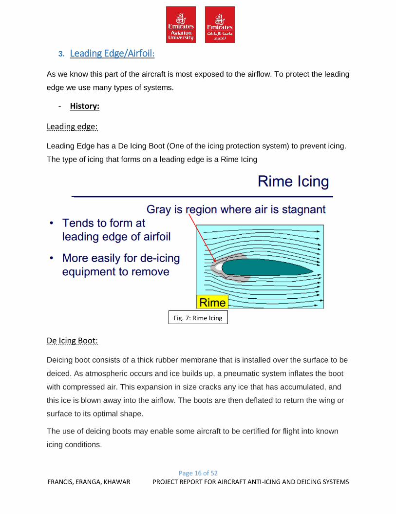
Fig. 7: Rime Icing
3. Leading Edge/Airfoil:
As we know this part of the aircraft is most exposed to the airflow. To protect the leading
edge we use many types of systems.
- History:
Leading edge:
Leading Edge has a De Icing Boot (One of the icing protection system) to prevent icing.
The type of icing that forms on a leading edge is a Rime Icing
De Icing Boot:
Deicing boot consists of a thick rubber membrane that is installed over the surface to be
deiced. As atmospheric occurs and ice builds up, a pneumatic system inflates the boot
with compressed air. This expansion in size cracks any ice that has accumulated, and
this ice is blown away into the airflow. The boots are then deflated to return the wing or
surface to its optimal shape.
The use of deicing boots may enable some aircraft to be certified for flight into known
icing conditions.
Page 17 of 52 FRANCIS, ERANGA, KHAWAR PROJECT REPORT FOR AIRCRAFT ANTI-ICING AND DEICING SYSTEMS
Several disadvantages are associated with the use of deicing boots. Boots need to be
replaced frequently (on the order of 2–3 years and require proper care. Holes in the boot
may create air leaks that will decrease the effectiveness of the boots. As such, boots
must be carefully inspected before each flight and any holes or cuts must be patched.
The use of boots may not be sufficient to handle extremely severe icing. In these cases,
ice can accumulate faster than the boots can shed it, or ice can accumulate on non-
booted surfaces to the point where it disrupts airflow enough to cause a dangerous loss
of lift or control.
Deicing boots are most commonly seen on medium-sized airliners and utility aircraft.
Larger airliners and military jets tend to use heating systems that are installed
underneath the wing's leading edge, keeping it constantly warm and preventing ice from
forming.
- Project Model
For our project we have selected the boot strap de-icing system. This system works on
the principle of pneumatics. As the air enters the multiple tubes which have been placed
on the leading edge of the airfoil they inflate since they have been made from a
rubberized material. These smaller tubes which have been placed length wise will intern
inflate a larger sheet of rubber which helps make the entire airfoil streamlined; when this
larger rubber inflates it cracks t hive which has been formed over the airfoil. The ice
clears off with the help of the speed of airflow towards the aircraft due to its speed.
Hence we use a compressor which has a capacity of 150psi. When the tubes inflate
they tend to change the shape of the leading edge.
i. Electrical anti-icing:
This system uses a method called Spraymat. Spraymats are basically heater mats
where electrical current causes the mats to heat which in form melts the ice and
removed by the aircrafts airflow. There are anti-icing and de-icing spray mats. Where for
anti-icing it’s switched on continuously and for de-icing it’s switched on and off
according to a time interval. The power being used to heat the mats are about 115 to
Page 18 of 52 FRANCIS, ERANGA, KHAWAR PROJECT REPORT FOR AIRCRAFT ANTI-ICING AND DEICING SYSTEMS
200 volts variable frequency AC for heating, & for control its 115 volts AC and 28 volts
DC.
Spraymat is constructed in layers on resin impregnated glass fibre cloth insulation which
is then sandwiched with a metallic heater element in each of the layers. “It is then
prefabricated and then bonded by adhesive into a recess on the structural component to
be protected”. The system switches on and off by ice sensing devices. When the
system is idle certain amount of ice is allowed to form then the system activates causing
the ice to crack the removed by the airflow. The Spraymat is controlled in temperatures
between 50C to 100C.
ii. Chemical de-icing:
This de-icing system consists of de-icing fluid which is stored in a tank. When needed it
is drawn into by an electrical driven gear pump then into micro filters then distributed
through many number of porous stainless steel distributer panels. The panels are
constructed in the shape of a wing and tail unit then installed into the leading edge.
Each panel contains number of pours where fluid is distributed to the outer skin after
passing into a cavity then through a porous plastic sheet. The fluid causes the ice to dis-
bond loosening the ice formation then removed completely by the airflow.
iii. Thermal anti-icing: For a thermal system it needs some kind of heated air supply, this is provided either by
heating ram air passing it through a heat exchanger (located in the exhaust system of
the gas turbine engine) or by the turbine engine compressor where hot air can be bled.
The leading edges of the wings and tail units are installed with an inner skin layer;
where small pores or gaps are situated inside the leading edge. The gaps or pores are
for the heated air which will be ducted into the wings and tail units. Sufficient heated air
is passed through the outer skin of the leading edges to melt the ice and preventing ice
to be formed again.
iv. Pneumatic de-icing:
In this system; rubber boots containing several tubes inflates and deflates. It’s made
from soft pliable rubberized fabric and neoprene used for the outer ply. Neoprene can
Page 19 of 52 FRANCIS, ERANGA, KHAWAR PROJECT REPORT FOR AIRCRAFT ANTI-ICING AND DEICING SYSTEMS
withstand any abrasion and deterioration and can dissipate static electricity. This is a
de-icing system. The whole boot is bonded onto the leading edge.
When ice is formed the rubber boot inflates several tubes causing a swell on the on the
leading edge which break the ice apart then removed completely by the airflow. The
boots are deflated by a vacuum then helps to shape the airfoil back.
As for our model we are using a pneumatic boot de-icing system in the leading
edge/Airfoil. Rubber tubes are used for the inflation and deflation of the tubes. Which
will cause the ice to break and is removed by the airflow. There will be two air
compressors one for inflating the tubes and the other for deflating the tubes. The
inflation and deflation of the tubes will be controlled by solenoid valves. The main power
supply will be provided by a car battery. Each inflating/deflating tubes are
interconnected by rubber pipelines. Which will be further connected using T-connectors
to the solenoid valve.
- Types of components:
1. Cycle rubber tubes: This will used for the inflation/deflation of the tubes, as these
tubes will be used for de-icing.
2. Rubber Sheet: This will be placed on top of the cycle rubber tubes which prevents the
rubber tunes from shifting. Hence also used to show the smoothness on the
airfoil/leading edge.
3. Pop Rivets: These are used for the attachment of the rubber sheet to the aluminum.
4. Solenoid Valve: This consists of a gate system which will block one side of the entry
causing the other side to operate. Vice-versa.
5. Switch: This will be used to start the system.
6. Compressors: There are two compressors used. One will be used for inflation and the
other used for deflation. As it will provide air into the tubes as well as suck out the air
from the tubes.
7. Battery: This the main power source which will drive the air compressors for the
operation of the pneumatic system.

Page 20 of 52 FRANCIS, ERANGA, KHAWAR PROJECT REPORT FOR AIRCRAFT ANTI-ICING AND DEICING SYSTEMS
8. Rubber Pipes: These are small pipes through which the air will be passed to the
tubes to inflate/deflate.
Page 21 of 52 FRANCIS, ERANGA, KHAWAR PROJECT REPORT FOR AIRCRAFT ANTI-ICING AND DEICING SYSTEMS
Types of Ice Detectors:
There are 3 different types of ice detectors:
1. Pressure Operated Ice Detector Head:
This ice detector consists of a short stainless steel, or chromium plated brass tube,
closed at its outer end. It is mounted so that it projects vertically downwards from a
position on the aircraft known to be susceptible to icing. Four small holes are drilled in
the leading edge of this tube. In the trailing edge are two holes having less total area
than those in the leading edge. The heater element is fitted in the ice detector tube to
allow it to be cleared of ice.
During normal flight, pressure is built up inside the tube and is transmitted by tubing to a
capsule. The causes the capsule to expand and separates a pair of electrical contacts.
When icing conditions are met, ice will form on the leading edge of the tube and close
off the holes. The holes in the trailing edge will not be covered by ice and the airflow will
now tend to exhaust the system. This will collapse the relay capsule and close the
contacts. The closed contacts will complete a circuit to illuminate a warning indicator in
the control cabin. At the same time the heater in the ice detector is switched on. This
heater clears ice from the detector before being switched off, allowing continued
detection of icing conditions. This cycling of the ice detector will continue until icing
conditions no longer exist.
2. Serrated Rotor Ice Detector Head:
The ice detector consists of a serrated rotor driven by a small AC motor via a reduction
gearbox; the serrated rotor is rotated close to a foxed knife edge cutter. The motor
casing is connected via a spring tensioned toggle bar to a switch assembly. The motor
and switch assembly is enclosed within a sealed cylindrical housing.
The ice detector is mounted on the side of the aircraft fuselage, so that only the serrated
rotor and knife edge are exposed to the airflow.
Page 22 of 52 FRANCIS, ERANGA, KHAWAR PROJECT REPORT FOR AIRCRAFT ANTI-ICING AND DEICING SYSTEMS
During flight the serrated motor on the detector head is continuously driven by the
electric motor. Under no icing conditions there is no opposing torque and the switch
contacts remain open. In icing conditions, ice builds up on the rotor and is shaved off by
the knife edge. This procedure a substantial increase in the torque required to drive the
rotor. This causes the switch contacts to close, illuminating a warning light in the control
cabin. Once icing conditions cease, the knife edge cutter will no longer shave ice. The
torque loading will reduce and allow the motor to return to its normal position. This
opens the switch contacts and switches off the warning light in the control cabin.
3. Vibrating Rod Ice Detector Head:
This ice detector senses the presence of icing conditions and provides an indication in
the flight compartment that such conditions exist. The system consists of a solid-state
ice detector and advisory warning light. The ice detector is attached to the fuselage with
its probe protruding through the skin. The ice detector probe (exposed to the airstream)
is an ice sensing element that ultrasonically vibrates in an avail mode of its own
resonant frequency of approximately 40 KHz.
When ice form the sensing element, the probe frequency decreases. The ice detector
circuit detects the change in probe frequency by comparing it with a reference oscillator.
At a pre-determined frequency change (proportional to ice build-up), the ice detector
circuit is activated. Once activated, the ice warning light in the flight compartment is
illuminated and a time circuit is triggered. The operation of the time circuit switches a
probe heater on for a set period of time to remove the ice form the probe. After the timer
has timed out, it switches off the ice warning indicator and returns the system to a
detector mode, providing that icing conditions no longer exist. If, however, a further ice
warning signal is received during the timer period, the timer will be re-triggered, the
warning light will remain on and the heater will again be selected on. This cycle will be
repeated for as long as the icing conditions prevail.
Page 23 of 52 FRANCIS, ERANGA, KHAWAR PROJECT REPORT FOR AIRCRAFT ANTI-ICING AND DEICING SYSTEMS
Design concept of the model:
Survey:
1. Windshield:
- Windshield wiper systems:
In an electrical windshield wiper system, the wiper blades are driven by an electric
motor that receives power from the aircraft’s electrical system. On some aircraft, the
pilot’s and copilot’s windshield wipers are operated by separate systems to ensure that
clear vision is maintained through one of the windows should one system fail. Each
windshield wiper assembly consists of a wiper, wiper arm, and a wiper motor/converter.
Almost all windshield wiper systems use electrical motors. Some older aircraft might be
equipped with hydraulic wiper motors.
Maintenance performed on windshield wiper systems consists of operational checks,
adjustments, and troubleshooting. An operational check should be performed whenever
a system component is replaced or whenever the system is suspected of not working
properly. During the check, make sure that the windshield area covered by the wipers is
free of foreign matter and is kept wet with water. Adjustment of a windshield wiper
system consists of adjusting the wiper blade tension, the angle at which the blade
sweeps across the windshield, and proper parking of the wiper blades.
Issue: Windshield wipers characteristically have two basic problem areas. One is the
tendency of the slipstream aerodynamic forces to reduce the wiper blade loading
pressure on the window, causing ineffective wiping or streaking. The other is in
achieving fast enough wiper oscillation to keep up with high rain impingement rates
during heavy rain falls.
- Electric:
High performance and transport category aircraft windshields are typically made of
laminated glass, polycarbonate, or similar ply material. Typically clear vinyl plies are
also included to improve performance characteristics. The laminations create the
Page 24 of 52 FRANCIS, ERANGA, KHAWAR PROJECT REPORT FOR AIRCRAFT ANTI-ICING AND DEICING SYSTEMS
strength and impact resistance of the windshield assembly. These are critical feature for
windshields as they are subject to a wide range of temperatures and pressures. They
must also withstand the force of a 4 pound bird strike at cruising speed to be certified.
The laminated construction facilitates the inclusion of electric heating elements into the
glass layers, which are used to keep the windshield clear of ice, frost, and fog. The
elements can be in the form of resistance wires or a transparent conductive material
may be used as one of the window plies. To ensure enough heating is applied to the
outside of the windshield, heating elements are placed on the inside of the outer glass
ply. Windshields are typically bonded together by the application of pressure and heat
without the use of cement.
2. Pitot Tube:
We chose an electrical anti-icing system over a hot air system because for a hot air
system the air must be bled either from the APU or from the engine compressors. The
main disadvantage of this system is that to supply hot air to each and every Pitot tube
which will increase the piping and also the weight of the aircraft. And it was very
complicated for us to choose this particular system.
As we are preparing the electrical anti-icing system, it was challenging hence the
components required for example, heating strips was very easy to operate as well as to
connect to the terminals of the hearting iron tube. This system required less
components compared to the hot air de-icing system. The electrical anti-icing system is
more efficient because the whole of the Pitot tube will be heated therefore preventing
any ice to form on the Pitot tube. As for the hot air anti-icing system the hot air provided
will have less of an effect on the Pitot tube compared to the electrical system because
only the nozzle of the Pitot tube will receive much of the hot air and the less of hot air in
the surroundings. Most importantly the electrical system only heats the pitot tube
therefore the electrical anti-icing system doesn’t interfere with the pitot tubes operation
hence the airflow towards the pitot tube. This results to the reading accuracy of the
aircrafts speed, VSI and altitude. As for the hot air anti-icing system the mixture of the
hot air and cold are in high altitudes will cause more interference of the pitot tubes
operation resulting to less reading accuracy of the aircrafts speed, VSI and altimeter.
Page 25 of 52 FRANCIS, ERANGA, KHAWAR PROJECT REPORT FOR AIRCRAFT ANTI-ICING AND DEICING SYSTEMS
3. Airfoil:
- Pneumatic Bootstrap system over Fluid system:
The fluid de-icing system requires a tank and aviation grade fluid which first is very
difficult to get and the tank should be connected with gear mechanisms to control the
fluid down the tubes and into the panel where fluid will be passed through the pores of
the panel. Furthermore fluid might be dangerous when it comes in contact with a
person and will be difficult to manage as well as it should have a safe place to operate it
and lastly as we will be testing it we may need right amount of quantity hence it might
increase the cost for the overall project.
Secondly, as we have chosen pneumatic de-icing system it has more advantages than
fluid because for the operation of pneumatic we need rubber tubes and a power supply
for inflation and deflation. This system more effective as we need to supply power for
the operation so we can say that it is easy to operate. Pneumatic de-icing will be more
efficient than fluid because as it inflates it will break the ice immediately and for fluid it
will take time to spread it on all the area on the leading edges. Furthermore, carrying a
fluid for the de-icing system it will be an additional weight on the aircraft as pneumatic
doesn’t has any weight to carry.
Page 26 of 52 FRANCIS, ERANGA, KHAWAR PROJECT REPORT FOR AIRCRAFT ANTI-ICING AND DEICING SYSTEMS
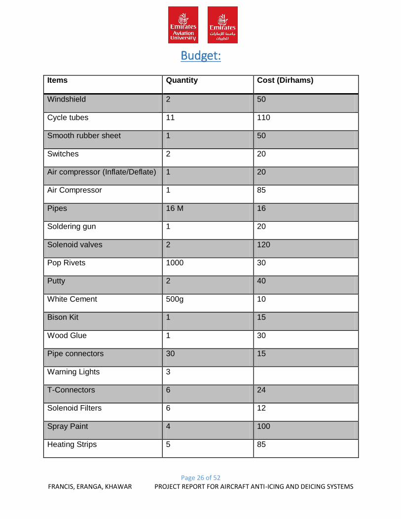
Budget:
Items Quantity Cost (Dirhams)
Windshield 2 50
Cycle tubes 11 110
Smooth rubber sheet 1 50
Switches 2 20
Air compressor (Inflate/Deflate) 1 20
Air Compressor 1 85
Pipes 16 M 16
Soldering gun 1 20
Solenoid valves 2 120
Pop Rivets 1000 30
Putty 2 40
White Cement 500g 10
Bison Kit 1 15
Wood Glue 1 30
Pipe connectors 30 15
Warning Lights 3
T-Connectors 6 24
Solenoid Filters 6 12
Spray Paint 4 100
Heating Strips 5 85
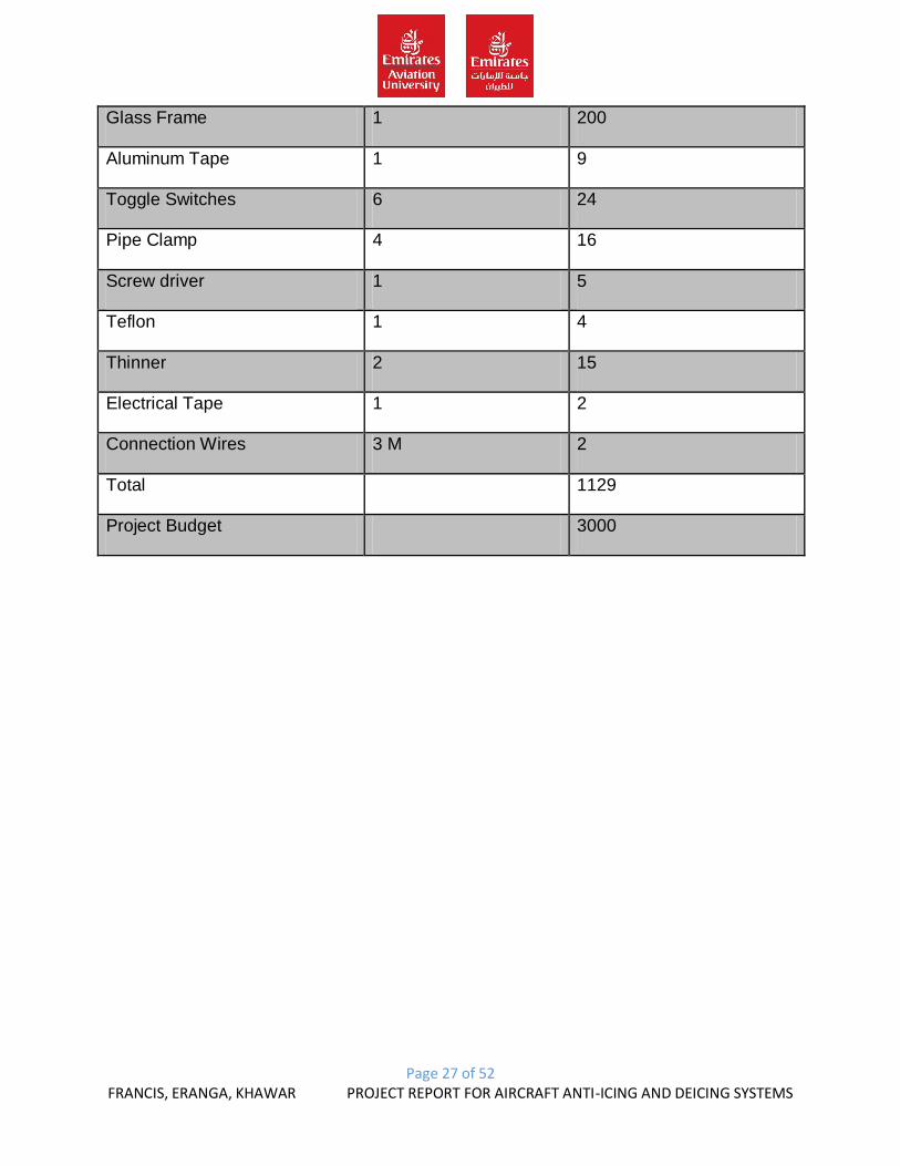
Page 27 of 52 FRANCIS, ERANGA, KHAWAR PROJECT REPORT FOR AIRCRAFT ANTI-ICING AND DEICING SYSTEMS
Glass Frame 1 200
Aluminum Tape 1 9
Toggle Switches 6 24
Pipe Clamp 4 16
Screw driver 1 5
Teflon 1 4
Thinner 2 15
Electrical Tape 1 2
Connection Wires 3 M 2
Total 1129
Project Budget 3000

Page 28 of 52 FRANCIS, ERANGA, KHAWAR PROJECT REPORT FOR AIRCRAFT ANTI-ICING AND DEICING SYSTEMS
Initial Sketch / Final Sketch:
1. Pitot tube:
HAND DRAWN SEPARATELY

Page 29 of 52 FRANCIS, ERANGA, KHAWAR PROJECT REPORT FOR AIRCRAFT ANTI-ICING AND DEICING SYSTEMS
2. Windshield:
HAND DRAWN SEPARATELY

Page 30 of 52 FRANCIS, ERANGA, KHAWAR PROJECT REPORT FOR AIRCRAFT ANTI-ICING AND DEICING SYSTEMS

Page 31 of 52 FRANCIS, ERANGA, KHAWAR PROJECT REPORT FOR AIRCRAFT ANTI-ICING AND DEICING SYSTEMS
3. Leading Edge / Airfoil:
HAND DRAWN SEPARATELY

Page 32 of 52 FRANCIS, ERANGA, KHAWAR PROJECT REPORT FOR AIRCRAFT ANTI-ICING AND DEICING SYSTEMS
Page 33 of 52 FRANCIS, ERANGA, KHAWAR PROJECT REPORT FOR AIRCRAFT ANTI-ICING AND DEICING SYSTEMS
Construction of the model
Materials Required:
1. Airfoil:
- Aluminum Sheets: because these are light in weight compared to metal.
- Rubber sheet: because it provide a smoother surface compared to fabric.
- Cycle tubes: because they expanded to our requirements.
- Pop Rivets: because easier to rivet and remove and light in weight than other
rivets.
- Bison kit: this we used to attach the end of the rubber sheet with the end of the
aluminum sheet.
2. Windshield:
- Heating element (titanium): because it’s light in weight and gets heated quickly
and cools off quickly compared to copper.
- Wood frame: used to keep the glass in place hence easier to curve sharp edges
and to avoid movement in the glass compared to metal frame.
3. Pitot tube:
- Aluminum pipes: easier to shape the Pitot tube hence absorbs heat slowly
compares to metal.
- Heating tube: Used for the heating of the pitot tube compared to any wire heating
element as it takes more time to heat.
- Super glue: this is used for the connection of the pitot tubes joints.
- Pipe clamp: this we used for holding the Pitot tube in place on the board.
Page 34 of 52 FRANCIS, ERANGA, KHAWAR PROJECT REPORT FOR AIRCRAFT ANTI-ICING AND DEICING SYSTEMS
Tools required and their use:
- Pop Rivet gun: These are used for manual riveting of the pop rivet and are
portable than hoses.
- Mallet: Used to straightening and bending of the aluminum sheets.
- Files: many types of files used to shape and smoothen the surface of the
aluminum.
- Guillotine metal cutter: Used to cut the aluminum sheet accurately as per our
requirements.
- Screw drivers: used to tighten the screws (+ -)
- Pneumatic Drill: Used to drill holes to fix in screws or screw clamps.
- Pneumatic air nozzle: Provides air in pressure.
- Bench Drill Machine: Used to drill materials for an accurate and steady hole.
- Hand Metal Cutter: Used to cut metal material handsfree.
- DC power supply: Used to provide external voltage power.
- Hacksaw: used to cut and chip off unwanted and wanted pieces.
- Scribbler: Used to mark required points.
- Plier: Used to loosen bolts.
- Wire cutter: Used to cut the skin of the wire.
- Blades: Used to cut required materials.
Page 35 of 52 FRANCIS, ERANGA, KHAWAR PROJECT REPORT FOR AIRCRAFT ANTI-ICING AND DEICING SYSTEMS
Step by Step Procedure with dimensions & pictures:
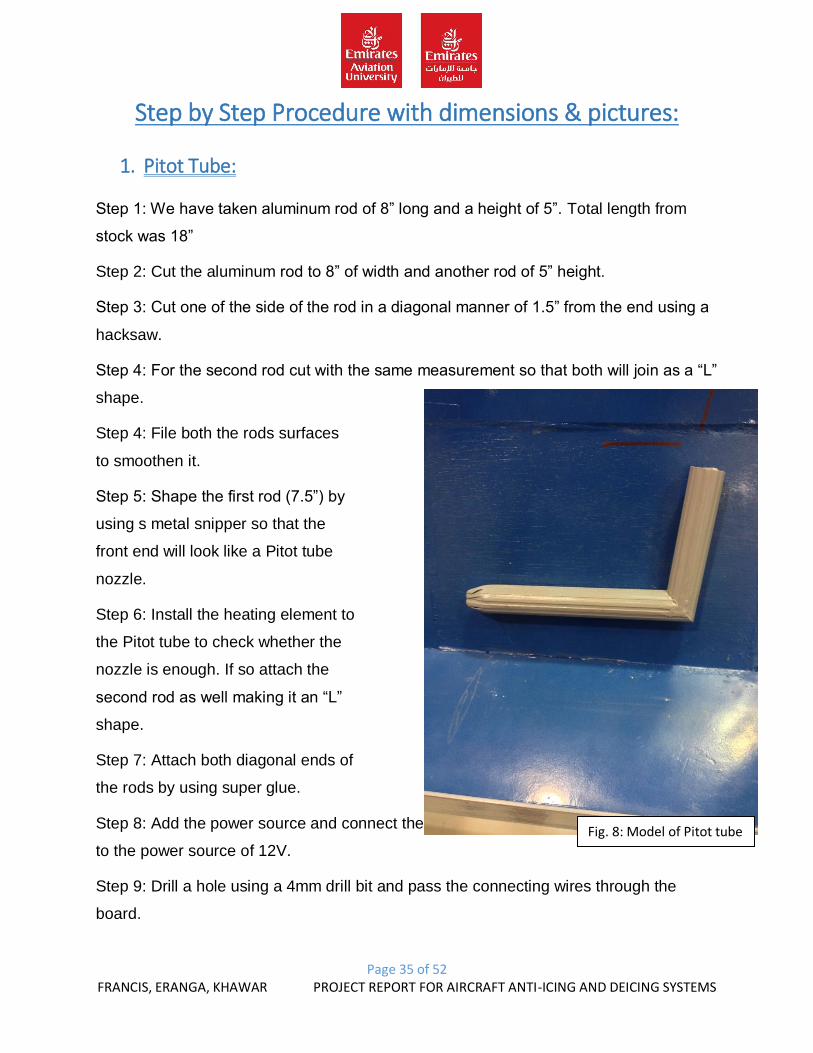
1. Pitot Tube:
Step 1: We have taken aluminum rod of 8” long and a height of 5”. Total length from
stock was 18”
Step 2: Cut the aluminum rod to 8” of width and another rod of 5” height.
Step 3: Cut one of the side of the rod in a diagonal manner of 1.5” from the end using a
hacksaw.
Step 4: For the second rod cut with the same measurement so that both will join as a “L”
shape.
Step 4: File both the rods surfaces
to smoothen it.
Step 5: Shape the first rod (7.5”) by
using s metal snipper so that the
front end will look like a Pitot tube
nozzle.
Step 6: Install the heating element to
the Pitot tube to check whether the
nozzle is enough. If so attach the
second rod as well making it an “L”
shape.
Step 7: Attach both diagonal ends of
the rods by using super glue.
Step 8: Add the power source and connect the heating terminals
to the power source of 12V.
Step 9: Drill a hole using a 4mm drill bit and pass the connecting wires through the
board.
Fig. 8: Model of Pitot tube
Page 36 of 52 FRANCIS, ERANGA, KHAWAR PROJECT REPORT FOR AIRCRAFT ANTI-ICING AND DEICING SYSTEMS
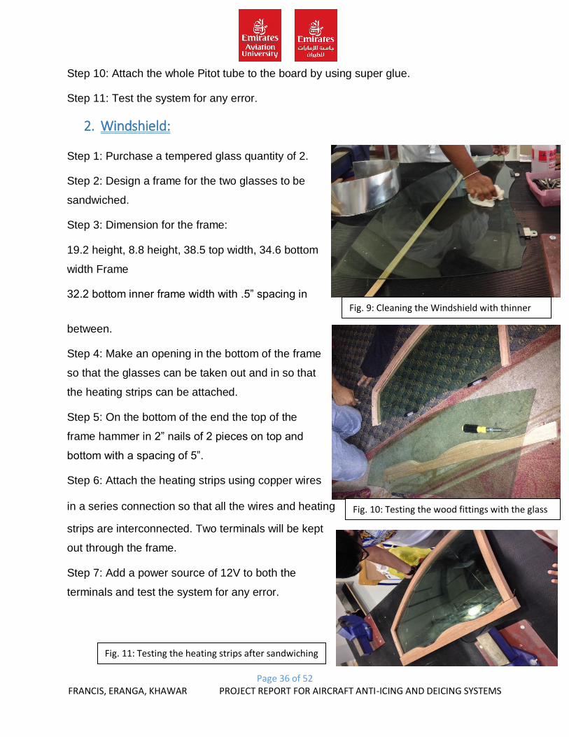
Fig. 10: Testing the wood fittings with the glass
Fig. 11: Testing the heating strips after sandwiching
Step 10: Attach the whole Pitot tube to the board by using super glue.
Step 11: Test the system for any error.
2. Windshield:
Step 1: Purchase a tempered glass quantity of 2.
Step 2: Design a frame for the two glasses to be
sandwiched.
Step 3: Dimension for the frame:
19.2 height, 8.8 height, 38.5 top width, 34.6 bottom
width Frame
32.2 bottom inner frame width with .5” spacing in
between.
Step 4: Make an opening in the bottom of the frame
so that the glasses can be taken out and in so that
the heating strips can be attached.
Step 5: On the bottom of the end the top of the
frame hammer in 2” nails of 2 pieces on top and
bottom with a spacing of 5”.
Step 6: Attach the heating strips using copper wires
in a series connection so that all the wires and heating
strips are interconnected. Two terminals will be kept
out through the frame.
Step 7: Add a power source of 12V to both the
terminals and test the system for any error.
Fig. 9: Cleaning the Windshield with thinner
Page 37 of 52 FRANCIS, ERANGA, KHAWAR PROJECT REPORT FOR AIRCRAFT ANTI-ICING AND DEICING SYSTEMS
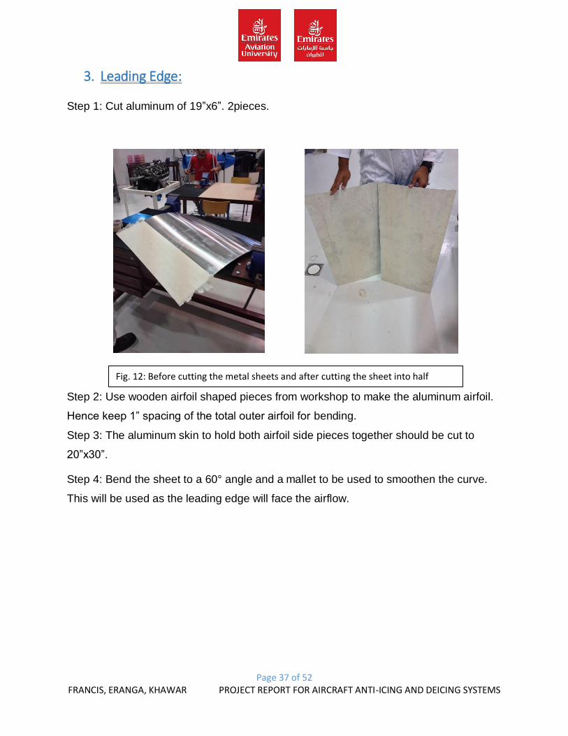
Fig. 12: Before cutting the metal sheets and after cutting the sheet into half
3. Leading Edge:
Step 1: Cut aluminum of 19”x6”. 2pieces.
Step 2: Use wooden airfoil shaped pieces from workshop to make the aluminum airfoil.
Hence keep 1” spacing of the total outer airfoil for bending.
Step 3: The aluminum skin to hold both airfoil side pieces together should be cut to
20”x30”.
Step 4: Bend the sheet to a 60° angle and a mallet to be used to smoothen the curve.
This will be used as the leading edge will face the airflow.
Page 38 of 52 FRANCIS, ERANGA, KHAWAR PROJECT REPORT FOR AIRCRAFT ANTI-ICING AND DEICING SYSTEMS
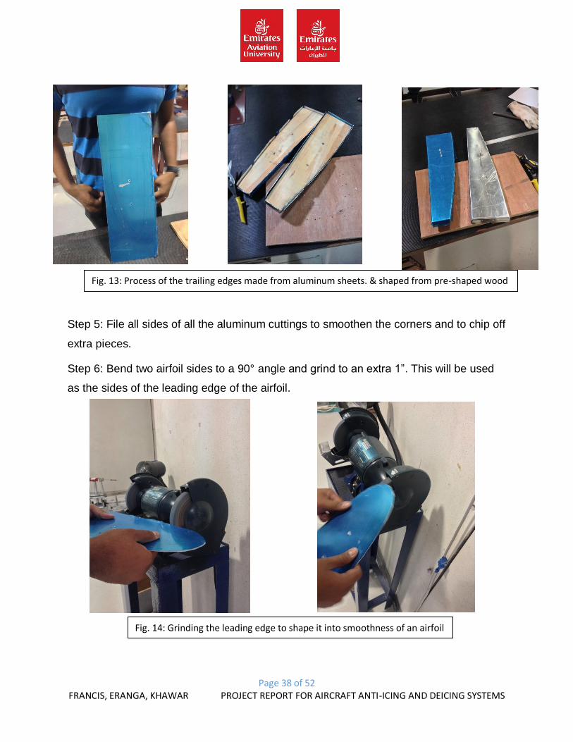
Fig. 13: Process of the trailing edges made from aluminum sheets. & shaped from pre-shaped wood
Step 5: File all sides of all the aluminum cuttings to smoothen the corners and to chip off
extra pieces.
Step 6: Bend two airfoil sides to a 90° angle and grind to an extra 1”. This will be used
as the sides of the leading edge of the airfoil.
Fig. 14: Grinding the leading edge to shape it into smoothness of an airfoil
Page 39 of 52 FRANCIS, ERANGA, KHAWAR PROJECT REPORT FOR AIRCRAFT ANTI-ICING AND DEICING SYSTEMS
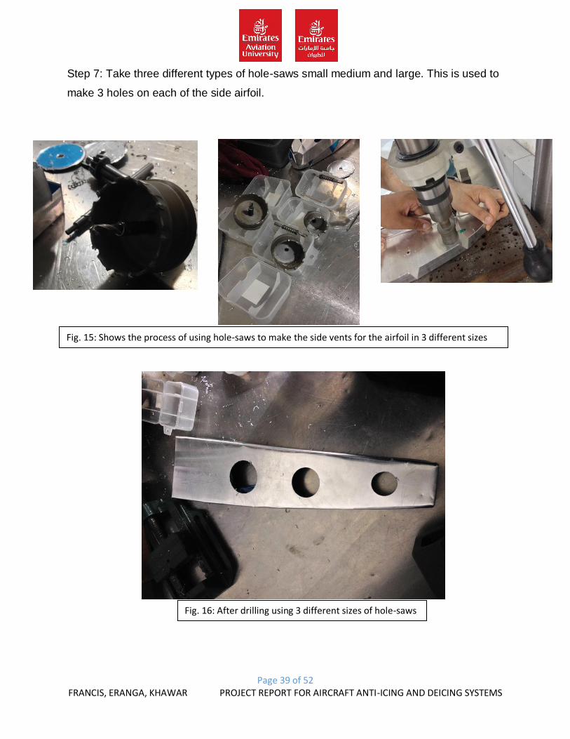
Step 7: Take three different types of hole-saws small medium and large. This is used to
make 3 holes on each of the side airfoil.
Fig. 15: Shows the process of using hole-saws to make the side vents for the airfoil in 3 different sizes
Fig. 16: After drilling using 3 different sizes of hole-saws
Page 40 of 52 FRANCIS, ERANGA, KHAWAR PROJECT REPORT FOR AIRCRAFT ANTI-ICING AND DEICING SYSTEMS
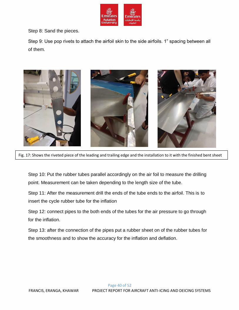
Step 8: Sand the pieces.
Step 9: Use pop rivets to attach the airfoil skin to the side airfoils. 1” spacing between all
of them.
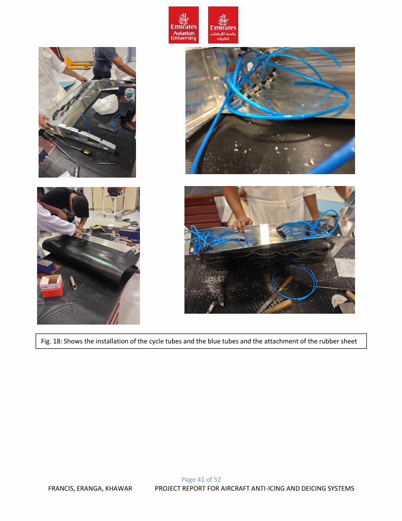
Step 10: Put the rubber tubes parallel accordingly on the air foil to measure the drilling
point. Measurement can be taken depending to the length size of the tube.
Step 11: After the measurement drill the ends of the tube ends to the airfoil. This is to
insert the cycle rubber tube for the inflation
Step 12: connect pipes to the both ends of the tubes for the air pressure to go through
for the inflation.
Step 13: after the connection of the pipes put a rubber sheet on of the rubber tubes for
the smoothness and to show the accuracy for the inflation and deflation.
Fig. 17: Shows the riveted piece of the leading and trailing edge and the installation to it with the finished bent sheet
Page 41 of 52 FRANCIS, ERANGA, KHAWAR PROJECT REPORT FOR AIRCRAFT ANTI-ICING AND DEICING SYSTEMS
Fig. 18: Shows the installation of the cycle tubes and the blue tubes and the attachment of the rubber sheet
Page 42 of 52 FRANCIS, ERANGA, KHAWAR PROJECT REPORT FOR AIRCRAFT ANTI-ICING AND DEICING SYSTEMS
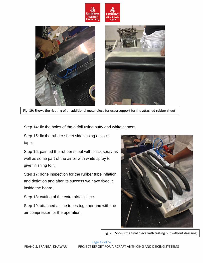
Step 14: fix the holes of the airfoil using putty and white cement.
Step 15: fix the rubber sheet sides using a black
tape.
Step 16: painted the rubber sheet with black spray as
well as some part of the airfoil with white spray to
give finishing to it.
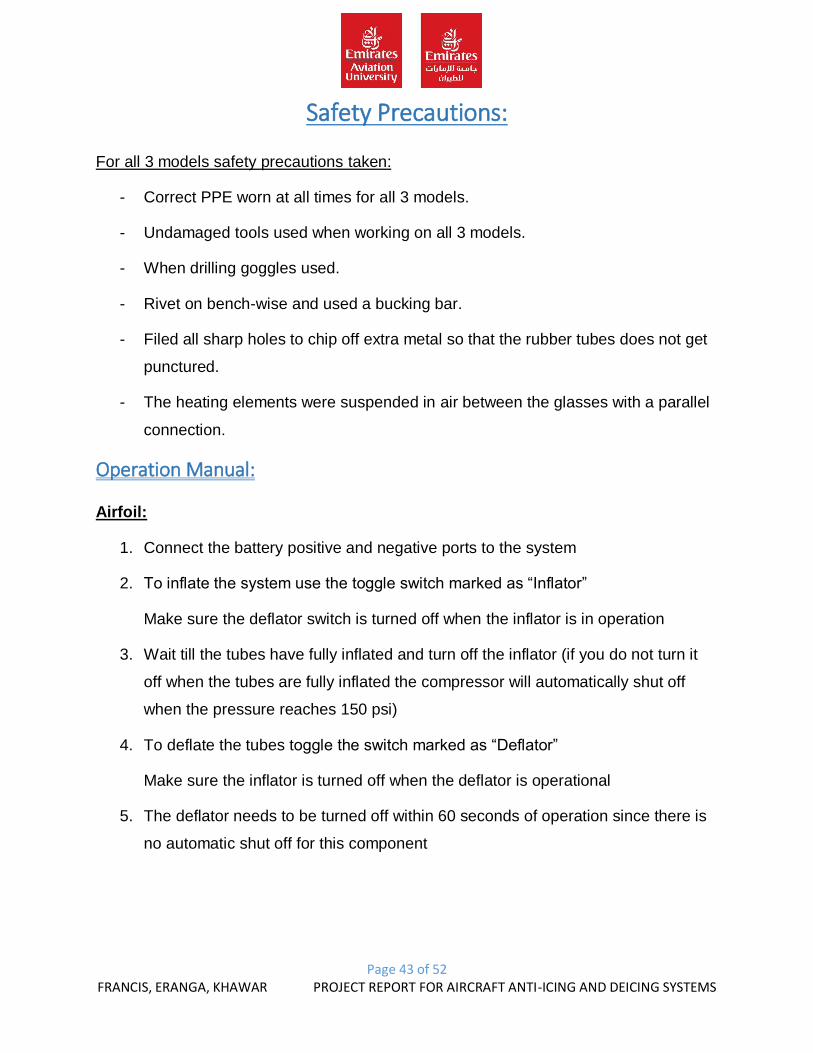
Step 17: done inspection for the rubber tube inflation
and deflation and after its success we have fixed it
inside the board.
Step 18: cutting of the extra airfoil piece.
Step 19: attached all the tubes together and with the
air compressor for the operation.
Fig. 19: Shows the riveting of an additional metal piece for extra support for the attached rubber sheet
Fig. 20: Shows the final piece with testing but without dressing
Page 43 of 52 FRANCIS, ERANGA, KHAWAR PROJECT REPORT FOR AIRCRAFT ANTI-ICING AND DEICING SYSTEMS
Safety Precautions:
For all 3 models safety precautions taken:
- Correct PPE worn at all times for all 3 models.
- Undamaged tools used when working on all 3 models.
- When drilling goggles used.
- Rivet on bench-wise and used a bucking bar.
- Filed all sharp holes to chip off extra metal so that the rubber tubes does not get
punctured.
- The heating elements were suspended in air between the glasses with a parallel
connection.
Operation Manual:
Airfoil:
1. Connect the battery positive and negative ports to the system
2. To inflate the system use the toggle switch marked as “Inflator”
Make sure the deflator switch is turned off when the inflator is in operation
3. Wait till the tubes have fully inflated and turn off the inflator (if you do not turn it
off when the tubes are fully inflated the compressor will automatically shut off
when the pressure reaches 150 psi)
4. To deflate the tubes toggle the switch marked as “Deflator”
Make sure the inflator is turned off when the deflator is operational
5. The deflator needs to be turned off within 60 seconds of operation since there is
no automatic shut off for this component
Page 44 of 52 FRANCIS, ERANGA, KHAWAR PROJECT REPORT FOR AIRCRAFT ANTI-ICING AND DEICING SYSTEMS
Pitot Tube:
1. Plug in the power cable into a 220v AC socket
2. Switch ON the toggle switch and let the tube heat
3. The switch can be left on for as long as needed and must be turned off when not
in use
WARNING: DO NOT TOUCH THE TUBE WHEN IN OPERATION SINCE IT
WILL BE VERY HOT!!
Windscreen:
1. Connect the wires to the battery terminals
2. Toggle the switch when there is any ice formed on the glass
3. Toggle the switch off when the glass is heated
WARNING: DO NOT OVER HAT THE GLASS AS IT CAN CRACK OR END UP
WITH BURNT PATCHES!!
Page 45 of 52 FRANCIS, ERANGA, KHAWAR PROJECT REPORT FOR AIRCRAFT ANTI-ICING AND DEICING SYSTEMS
Problems Faced:
1. Airfoil:
- When applied the putty it didn’t dry off even after 7days. Then we applied white
cement and sanded to the cement.
- Had issues with the deflation of the system but after another pump was installed
it is fine.
- Had major issues with the solenoid to get it functioning but it failed so removed it
from the design.
- The airfoil was too heavy to be supported alone through the display board. So
extra support and back fin bent towards the display board from behind.
2. Pitot tube:
- The issue with this model was the design how it should be connected and given
the heating source.
- The design was made given an “L” shape to it and a solder iron to provide the
heat to it.
- Also had an issue with the paint if it would melt but it fortunately didn’t.
3. Windshield:
- Faced major issues with the windshield when designing its frame and how to get
the heating element including how to suspend the heating element in air between
the sandwiched glasses.
- The other issue was to provide a power source to the terminals to manage and
compensate the heat by just the power supply and arrangement of the heating
elements.
Page 46 of 52 FRANCIS, ERANGA, KHAWAR PROJECT REPORT FOR AIRCRAFT ANTI-ICING AND DEICING SYSTEMS
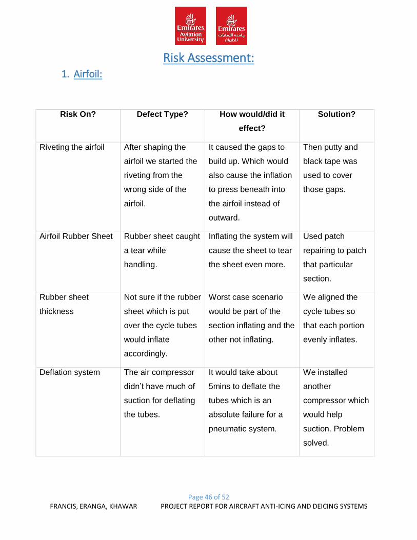
Risk Assessment: 1. Airfoil:
Risk On? Defect Type? How would/did it
effect?
Solution?
Riveting the airfoil After shaping the
airfoil we started the
riveting from the
wrong side of the
airfoil.
It caused the gaps to
build up. Which would
also cause the inflation
to press beneath into
the airfoil instead of
outward.
Then putty and
black tape was
used to cover
those gaps.
Airfoil Rubber Sheet Rubber sheet caught
a tear while
handling.
Inflating the system will
cause the sheet to tear
the sheet even more.
Used patch
repairing to patch
that particular
section.
Rubber sheet
thickness
Not sure if the rubber
sheet which is put
over the cycle tubes
would inflate
accordingly.
Worst case scenario
would be part of the
section inflating and the
other not inflating.
We aligned the
cycle tubes so
that each portion
evenly inflates.
Deflation system The air compressor
didn’t have much of
suction for deflating
the tubes.
It would take about
5mins to deflate the
tubes which is an
absolute failure for a
pneumatic system.
We installed
another
compressor which
would help
suction. Problem
solved.
Page 47 of 52 FRANCIS, ERANGA, KHAWAR PROJECT REPORT FOR AIRCRAFT ANTI-ICING AND DEICING SYSTEMS
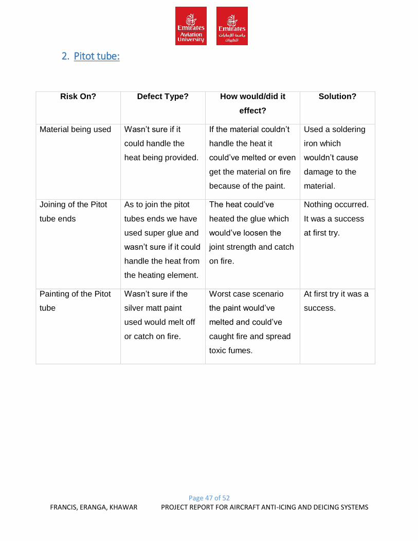
2. Pitot tube:
Risk On? Defect Type? How would/did it
effect?
Solution?
Material being used Wasn’t sure if it
could handle the
heat being provided.
If the material couldn’t
handle the heat it
could’ve melted or even
get the material on fire
because of the paint.
Used a soldering
iron which
wouldn’t cause
damage to the
material.
Joining of the Pitot
tube ends
As to join the pitot
tubes ends we have
used super glue and
wasn’t sure if it could
handle the heat from
the heating element.
The heat could’ve
heated the glue which
would’ve loosen the
joint strength and catch
on fire.
Nothing occurred.
It was a success
at first try.
Painting of the Pitot
tube
Wasn’t sure if the
silver matt paint
used would melt off
or catch on fire.
Worst case scenario
the paint would’ve
melted and could’ve
caught fire and spread
toxic fumes.
At first try it was a
success.
Page 48 of 52 FRANCIS, ERANGA, KHAWAR PROJECT REPORT FOR AIRCRAFT ANTI-ICING AND DEICING SYSTEMS
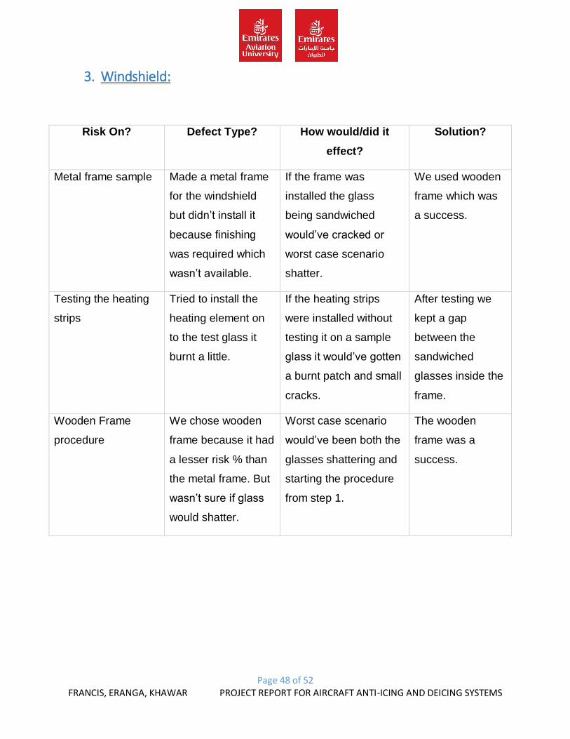
3. Windshield:
Risk On? Defect Type? How would/did it
effect?
Solution?
Metal frame sample Made a metal frame
for the windshield
but didn’t install it
because finishing
was required which
wasn’t available.
If the frame was
installed the glass
being sandwiched
would’ve cracked or
worst case scenario
shatter.
We used wooden
frame which was
a success.
Testing the heating
strips
Tried to install the
heating element on
to the test glass it
burnt a little.
If the heating strips
were installed without
testing it on a sample
glass it would’ve gotten
a burnt patch and small
cracks.
After testing we
kept a gap
between the
sandwiched
glasses inside the
frame.
Wooden Frame
procedure
We chose wooden
frame because it had
a lesser risk % than
the metal frame. But
wasn’t sure if glass
would shatter.
Worst case scenario
would’ve been both the
glasses shattering and
starting the procedure
from step 1.
The wooden
frame was a
success.
Page 49 of 52 FRANCIS, ERANGA, KHAWAR PROJECT REPORT FOR AIRCRAFT ANTI-ICING AND DEICING SYSTEMS
Future Improvements:
1. Airfoil:
- Better rubber tubes can be used to withstand more pressure.
- Air compressor of a larger pressure can be used.
- Airfoil shape can be improved if riveted in a better manner.
- Deflation process can be also achieved if we would’ve closed all the small
openings.
- The opening through the rubber tube and the airfoil skin can be used to
compensate with the outside airflow to balance the expansion rate.
- Could’ve made the airfoil lighter than it is now by using a lighter material and a
lighter rubber sheet.
- Could’ve used solenoid valve for better supply inflation and deflation.
2. Pitot tube:
- The shaping of the Pitot tube could’ve been made better.
- Better heating element could’ve been used. For example, heating wires.
- Better insulation can also be used.
- A better drainage system can be used.
3. Windshield:
- A better glass could’ve been used.
- A better heating element could’ve been used.
- The connection and arrangement of the heating element can be improved to a
parallel connection.
- The frame can be improved by making is smaller in size.
Page 50 of 52 FRANCIS, ERANGA, KHAWAR PROJECT REPORT FOR AIRCRAFT ANTI-ICING AND DEICING SYSTEMS
Conclusion
This project was very challenging and very interesting because the practical experience
is what interests’ most promising future engineers. This project was completed in less
than a month even though 2months was the original duration. This project is based on
anti-icing and de-icing systems. We have acknowledged different types of equipments
electrical connections and how to use and operate them for specific systems. This
relates to our project. We have made 3 models
1. Pitot tube.
2. Windshield.
3. Airfoil.
We found the Pitot tube to be easy of all of the models because the only difficulty we
had was to shape and install the heating element.
For the windshield it was very challenging because the frame dimensions and
installation of the heating element which had to be suspended in between the
sandwiched glasses.
The most difficult and challenging model was the airfoil where we had to manage and
compensate the inflation and deflation and pressure which is provided. We had a
problem which was the solenoid valves to we had to remove it from the system. But it
was a success.
Overall, this project was a success and thee most exciting project completed.
Page 51 of 52 FRANCIS, ERANGA, KHAWAR PROJECT REPORT FOR AIRCRAFT ANTI-ICING AND DEICING SYSTEMS
Reference
1. http://www.aboutflight.com/handbook-of-aeronautical-knowledge/ch-6-aircraft-
systems/anti-ice-and-deice-systems
2. http://www.vaisala.com/en/sustainability/cases/aircraftdeicing/Pages/default.aspx
3. http://www.aerotech.at/services.php?view=1
4. http://www.winterwind.se/category/blog/anti-icing-and-de-icing/
5. http://www.faa.gov/other_visit/aviation_industry/airline_operators/airline_safety/d
eicing/media/standardized_international_ground_deice_program.pdf
6. Aircraft System – Chapter Aircraft Protection Systems.
7. http://www.f-15e.info/joomla/technology/miscellaneous/102-anti-icing-systems
8. http://en.wikipedia.org/wiki/Pitot-static_system
9. http://aviation.about.com/od/Aircraft/a/Aircraft-Systems-Pitot-static-System.htm
10. http://greggordon.org/flying/CFIAILessonPlanPitotStaticSystem.htm
Picture References 1. Fig. 1: http://www.aboutflight.com/handbook-of-aeronautical-knowledge/ch-6-
aircraft-systems/anti-ice-and-deice-systems
2. Fig. 2: http://www.aboutflight.com/handbook-of-aeronautical-knowledge/ch-6-
aircraft-systems/anti-ice-and-deice-systems
3. Fig. 3: http://greggordon.org/flying/CFIAILessonPlanPitotStaticSystem.htm
4. Fig. 4: http://www.f-15e.info/joomla/technology/miscellaneous/102-anti-icing-
systems
5. Fig. 6: http://greggordon.org/flying/CFIAILessonPlanPitotStaticSystem.htm
6. Fig. 7: www.dept.aoe.vt.edu/~mason/Mason_f/AntiIcingT4.ppt
7. Figures 8 to 20: All hand taken photos for process of model.