DELUXE STITCHERfor future reference. If you have any questions, contact your local DeLuxe Stitcher...
60
Before using this Stitcher Head, all operators must study this manual and follow the safety warnings and instructions. Keep these instructions with the G8 Stitcher Head for future reference. If you have any questions, contact your local DeLuxe Stitcher Company Graphic Arts Representative or Distributor. G8 Stitcher Head OPERATION AND MAINTENANCE MANUAL Wire Sizes: 23-28 Ga. Round, 20x24 and 21x25 Flat Crown Size: 1/2” (13.5 mm) Capacity: 2 sheets to 5/16” (8 mm) Standard 2 sheets to 5/32” (4 mm) Loop Head Serial Number : Date Purchased : Where Installed: (make/model of machine) solving your wire stitching needs for 125 years... DELUXE STITCHER COMPANY INC. ®
Transcript of DELUXE STITCHERfor future reference. If you have any questions, contact your local DeLuxe Stitcher...

Before using this Stitcher Head, all operators must study this manual and follow the safety warnings and instructions. Keep these instructions with the G8 Stitcher Head for future reference. If you have any questions, contact your local DeLuxe Stitcher Company Graphic Arts Representative or Distributor.
G8 Stitcher HeadOPERATION AND MAINTENANCE MANUAL
Wire Sizes: 23-28 Ga. Round, 20x24 and 21x25 FlatCrown Size: 1/2” (13.5 mm)
Capacity: 2 sheets to 5/16” (8 mm) Standard2 sheets to 5/32” (4 mm) Loop
Head Serial Number : Date Purchased : Where Installed: (make/model of machine)
solving your wire stitching needs for 125 years...
DELUXE STITCHERC O M P A N Y I N C .
®

2

3

WARNING!
G8 Stitcher Head
Machine operators and others in the work area should always wearsafety glasses to prevent serious eye injury from
fasteners and flying debris when loading, operating,or unloading this machine.
Do not operate this stitcher head without all stitcher machine guards in place. Do not modify the guards in any way.Always disconnect the power supply before removing
any guards for servicing.
Never operate the machine with wire feeding throughthe head unless there is stock above the clinchers,
otherwise serious damage may result.
Always turn power off when making adjustments. Alwaysdisconnect the power cord before any disassembly work.
4
EYEWEAR
REQUIRED
6
Safety Warning .................................................................................5
Introduction ........................................................................................................7
Part Number Definition ....................................................................................7
Specifications .....................................................................................................9
Installation ......................................................................................................11 Pre-Inspection ................................................................................11 Inspection ......................................................................................11 Assembly Parts .............................................................................12 Mounting .................................................................................... 13-14
Operation .......................................................................................................15 Wire Threading .......................................................................... 15-16 Wire Straightening ..................................................................... 17-18 Adjustments and Settings .......................................................... 19-24
Maintenance ......................................................................................................25 Lubrication ................................................................................. 25-26 Cleaning ........................................................................................27 How to Order Spare Parts .............................................................28
Troubleshooting ................................................................................................29 Formed Staple Chart .................................................................. 30-31
Appendices ......................................................................................................32 Exploded Drawings with Part Number/Description/ Cross Reference/Qty. ................................................................. 32-50
Optional Equipment........................................................................51-52
Parts Index......................................................................................................53-55
Warranty........ .....................................................................................................56
Registration Card .......................................................................................... 57-58
Common Replacement Parts .......................................................................58
Table of Contents

7
The part number for each Stitcher Head can be used to define the stitcher head itself, in most cases. The Head’s model type, mounting style, nominal wire size and crown size can all be determined from the part number.
G8 P HD 24 A 1/2
1/2 = Crown size in inches A = Mount and Wire Guide Spring Type 24 = Wire Size HD = Head P = Original Equipment Manufacturer G8 = Model type
Part Number Definition
Typical Style Uses: G8BHD ............................................................. No. 2 and M2 Wire Stitchers G8MHD .......................................................... No. 17 and M17 Wire Stitchers G8HD .................................................................Automatic Saddle-Stitchers, ................................................................ Gang-Stitchers, Multibinders and Others
Examples of Replacement Heads for OEM Users*:
AM Graphics / Harris / Heidelberg / Sheridan 455, 562, 690 ............ G8HD24AAM Graphics / Harris / Heidelberg / Sheridan 705 ............................ G8HD24AC.P. Bourg ............................................................................................... G8HD24DChristensen .............................................................................................. G8HD24AHorizon SP, SPF ...................................................................................... G8HD24DMacey Multibinder ................................................................................ G8HD24BMcCain .................................................................................................... G8HD24ARosback ................................................................................................... G8HD24BBoewe 4601 .............................................................................................. G8BOHD241/2McCain / OmegaBinder.......................................................................... G8HD23AHarris 855 ................................................................................................ G8HD24-HARRISMcCain / Sheridan / Harris / Bielomatik, ECH Will \ et.al. ............... G8HDC24AHeidelberg ST100, ST270, ST300, ST350 ............................................. G8HEHD241/2JMZ&A (Parker) .................................................................................... G8PKHD241/2Watkiss .................................................................................................... G8WAHD241/2
* These are just a few examples of the replacement heads available for these OEM’s.
Introduction
8
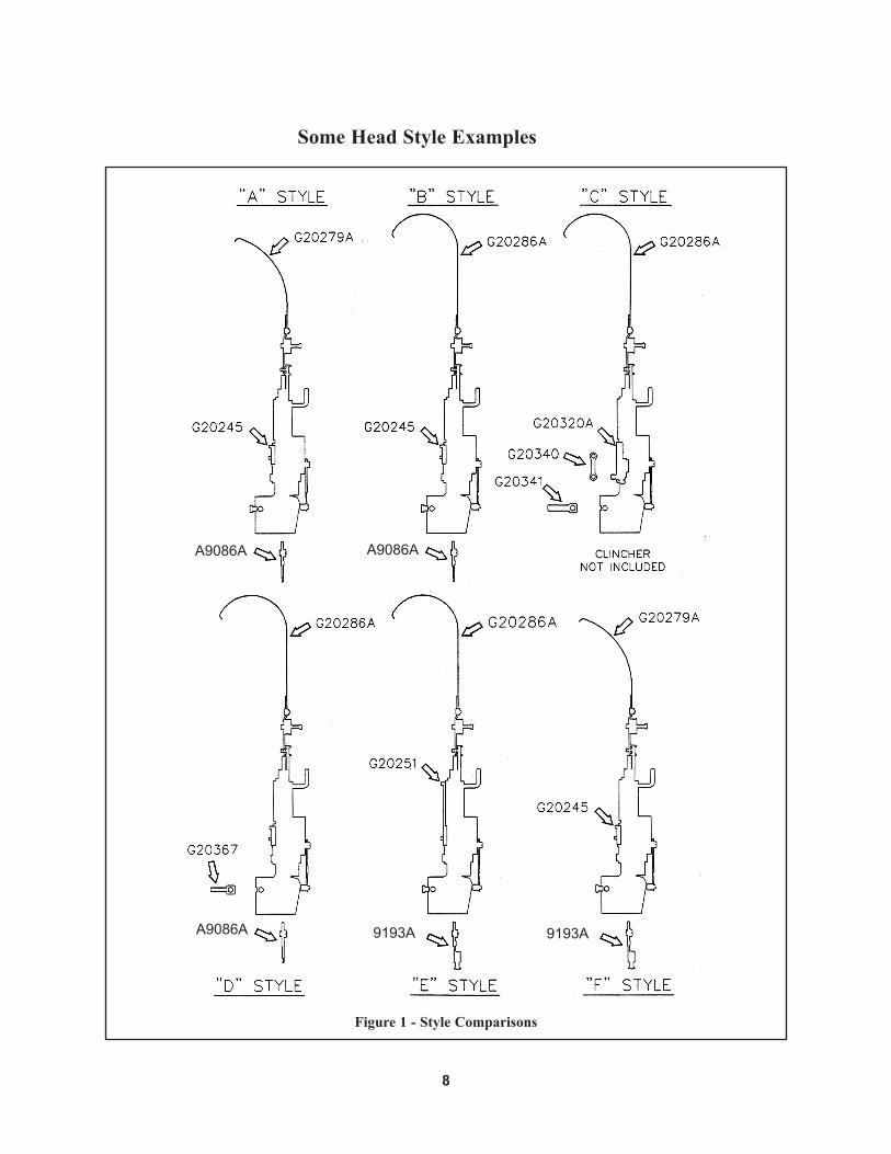
Some Head Style Examples
Figure 1 - Style Comparisons
A9086A A9086A
A9086A 9193A9193A
9
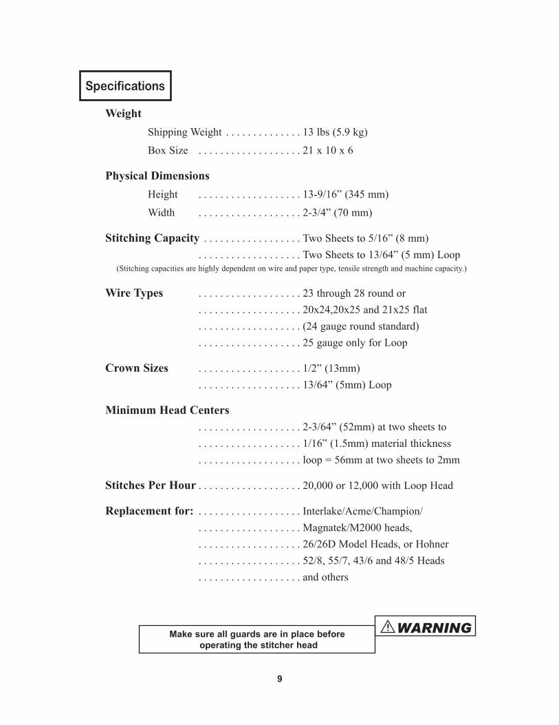
Specifications
Weight Shipping Weight . . . . . . . . . . . . . . 13 lbs (5.9 kg)
Box Size . . . . . . . . . . . . . . . . . . . 21 x 10 x 6
Physical Dimensions Height . . . . . . . . . . . . . . . . . . . 13-9/16 ” (345 mm)
Width . . . . . . . . . . . . . . . . . . . 2-3/4” (70 mm)
Stitching Capacity . . . . . . . . . . . . . . . . . . Two Sheets to 5/16” (8 mm) . . . . . . . . . . . . . . . . . . . Two Sheets to 13/64” (5 mm) Loop (Stitching capacities are highly dependent on wire and paper type, tensile strength and machine capacity.)
Wire Types . . . . . . . . . . . . . . . . . . . 23 through 28 round or . . . . . . . . . . . . . . . . . . . 20x24,20x25 and 21x25 flat . . . . . . . . . . . . . . . . . . . (24 gauge round standard) . . . . . . . . . . . . . . . . . . . 25 gauge only for Loop
Crown Sizes . . . . . . . . . . . . . . . . . . . 1/2” (13mm) . . . . . . . . . . . . . . . . . . . 13/64” (5mm) Loop
Minimum Head Centers . . . . . . . . . . . . . . . . . . . 2-3/64” (52mm) at two sheets to . . . . . . . . . . . . . . . . . . . 1/16” (1.5mm) material thickness . . . . . . . . . . . . . . . . . . . loop = 56mm at two sheets to 2mm
Stitches Per Hour . . . . . . . . . . . . . . . . . . . 20,000 or 12,000 with Loop Head
Replacement for: . . . . . . . . . . . . . . . . . . . Interlake/Acme/Champion/ . . . . . . . . . . . . . . . . . . . Magnatek/M2000 heads, . . . . . . . . . . . . . . . . . . . 26/26D Model Heads, or Hohner . . . . . . . . . . . . . . . . . . . 52/8, 55/7, 43/6 and 48/5 Heads . . . . . . . . . . . . . . . . . . . and others
Make sure all guards are in place before operating the stitcher head
WARNING!
10
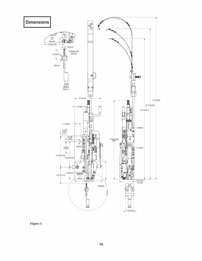
Dimensions
27 5/8 [702]
25 11/16 [653]
21 1/32 [611]
13 9/16 [345]MAX.
2 3/64 [52]
2 3/4" [70]2 1/4" [57]
2 7/16 [62]
1 3/8 [34.9]
2 13/16 [71.5]
4 23/64 [110.7]5 21/64 [135.3]
2 3/32 [53.3]
5/16 [8]
5/16 [8]
4 1/2 [114]
1 1/32 [26]
1 1/2 [38.5]
4 25/32 [121.4]
3 9/64 [80]
THICKNESSADJUSTMENT
THICKNESSADJUSTMENT
DRIVE STROKE
A
2.256 [57.30]5/32 [3.9]
1 3/16 [30.3]
3/8 [9.5]
DETAIL A SCALE 1.5 : 1
CENTER OFSTITCH
2 [50.8] .248 [6.3]
Figure 1
11
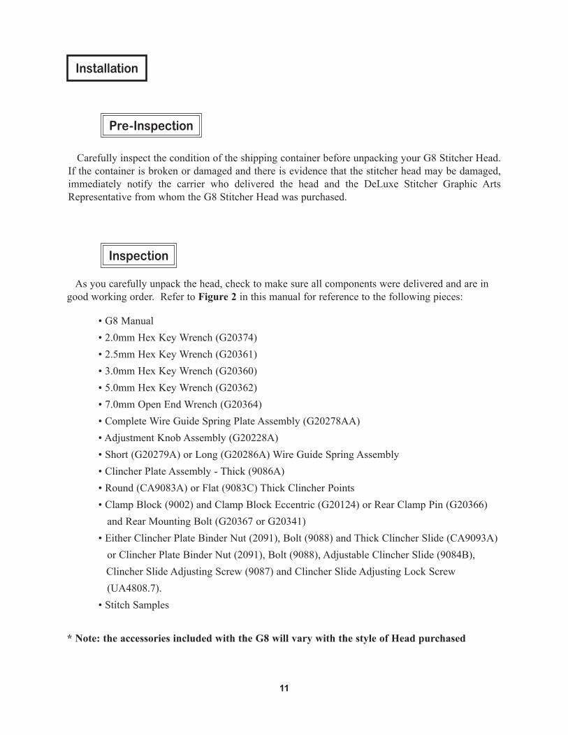
Installation
As you carefully unpack the head, check to make sure all components were delivered and are in good working order. Refer to Figure 2 in this manual for reference to the following pieces:
•G8Manual •2.0mmHexKeyWrench(G20374) •2.5mmHexKeyWrench(G20361) •3.0mmHexKeyWrench(G20360) •5.0mmHexKeyWrench(G20362) •7.0mmOpenEndWrench(G20364) •CompleteWireGuideSpringPlateAssembly(G20278AA) •AdjustmentKnobAssembly(G20228A) •Short(G20279A)orLong(G20286A)WireGuideSpringAssembly •ClincherPlateAssembly-Thick(9086A) •Round(CA9083A)orFlat(9083C)ThickClincherPoints •ClampBlock(9002)andClampBlockEccentric(G20124)orRearClampPin(G20366) and Rear Mounting Bolt (G20367 or G20341) •EitherClincherPlateBinderNut(2091),Bolt(9088)andThickClincherSlide(CA9093A) or Clincher Plate Binder Nut (2091), Bolt (9088), Adjustable Clincher Slide (9084B), Clincher Slide Adjusting Screw (9087) and Clincher Slide Adjusting Lock Screw (UA4808.7). •StitchSamples
* Note: the accessories included with the G8 will vary with the style of Head purchased
Carefully inspect the condition of the shipping container before unpacking your G8 Stitcher Head. If the container is broken or damaged and there is evidence that the stitcher head may be damaged, immediately notify the carrier who delivered the head and the DeLuxe Stitcher Graphic Arts Representative from whom the G8 Stitcher Head was purchased.
Pre-Inspection
Inspection
12
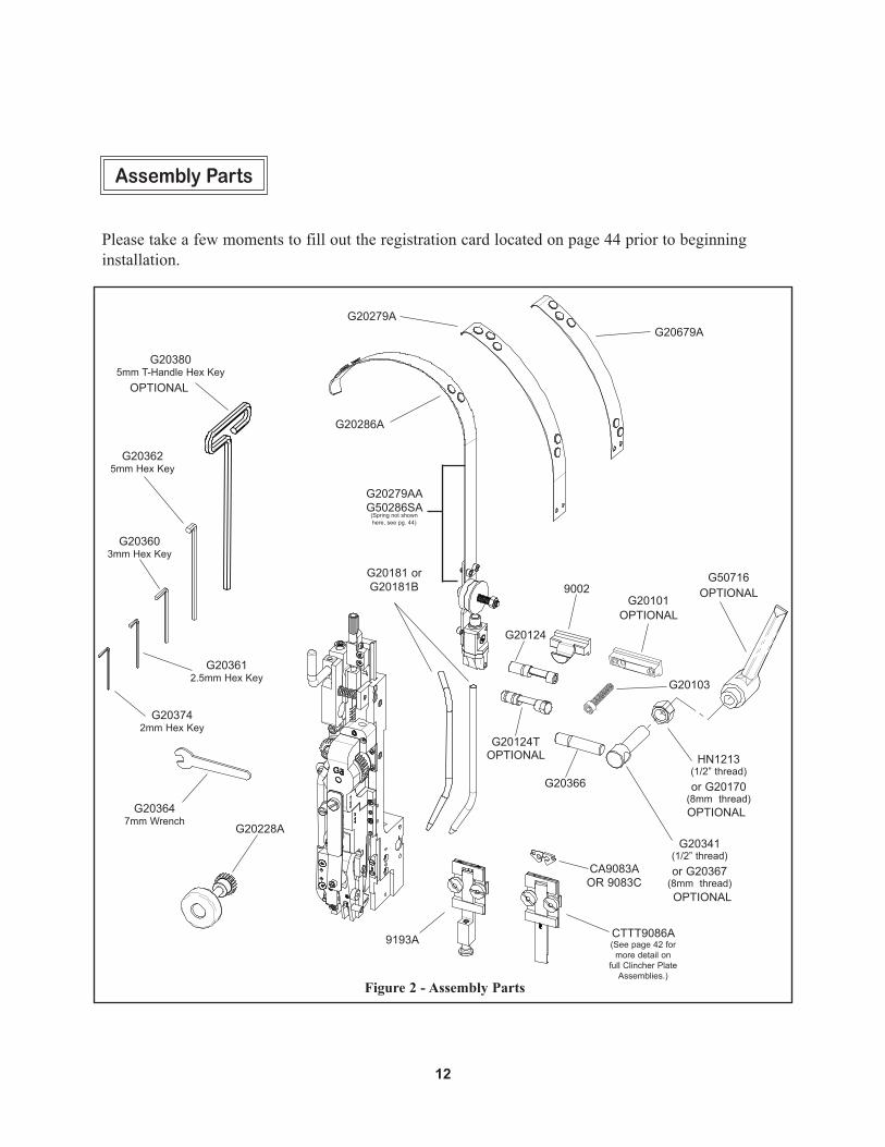
Please take a few moments to fill out the registration card located on page 44 prior to beginning installation.
Assembly Parts
Figure 2 - Assembly Parts
G20124
G203742mm Hex Key
G203612.5mm Hex Key
G203603mm Hex Key
G203625mm Hex Key
G203805mm T-Handle Hex Key
G20228A
G203647mm Wrench
CA9083A
9002G20101
G20366
G20341(1/2” thread)or G20367
(8mm thread)
G20279AAG50286SA
(Spring not shownhere, see pg. 44)
G20679A
G20181 orG20181B
CTTT9086A(See page 42 for
more detail on full Clincher Plate
Assemblies.)
G20286A
9193A
HN1213(1/2” thread)or G20170
(8mm thread)
OPTIONAL
G20279A
G50716OPTIONAL
OPTIONAL
OPTIONAL
OPTIONAL
G20103
OR 9083C
G20124TOPTIONAL
13
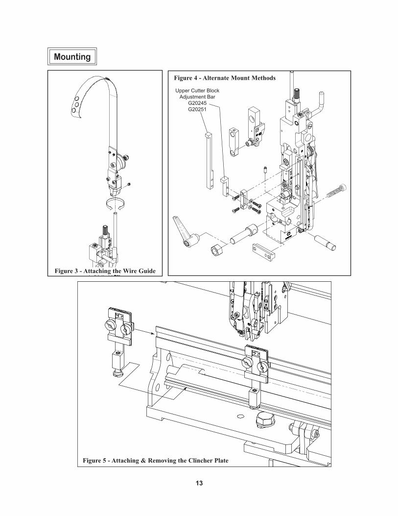
Mounting
Figure 5 - Attaching & Removing the Clincher Plate
Figure 3 - Attaching the Wire Guide
Figure 4 - Alternate Mount Methods
Upper Cutter Block Adjustment Bar
G20245G20251
14
LIN
E U
P G
RO
OV
ES
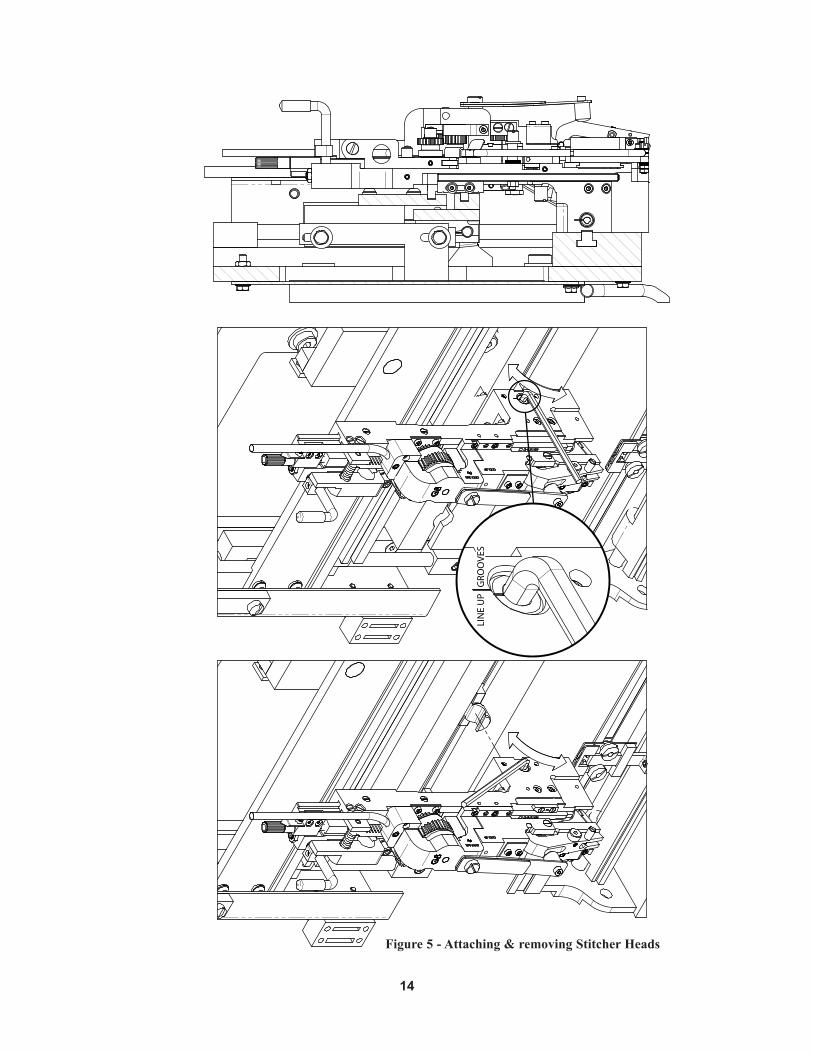
Figure 5 - Attaching & removing Stitcher Heads
15
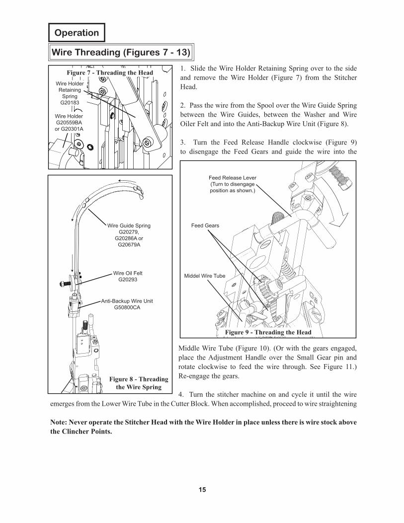
Middle Wire Tube (Figure 10). (Or with the gears engaged, place the Adjustment Handle over the Small Gear pin and rotate clockwise to feed the wire through. See Figure 11.) Re-engage the gears.
4. Turn the stitcher machine on and cycle it until the wire emerges from the Lower Wire Tube in the Cutter Block. When accomplished, proceed to wire straightening
Note: Never operate the Stitcher Head with the Wire Holder in place unless there is wire stock above the Clincher Points.
1. Slide the Wire Holder Retaining Spring over to the side and remove the Wire Holder (Figure 7) from the Stitcher Head.
2. Pass the wire from the Spool over the Wire Guide Spring between the Wire Guides, between the Washer and Wire Oiler Felt and into the Anti-Backup Wire Unit (Figure 8).
3. Turn the Feed Release Handle clockwise (Figure 9) to disengage the Feed Gears and guide the wire into the
Operation
Wire Threading (Figures 7 - 13)
Feed Release Lever(Turn to disengage position as shown.)
Figure 9 - Threading the Head
Figure 7 - Threading the HeadWire Holder Retaining
SpringG20183
Wire Guide SpringG20279,
G20286A orG20679A
Anti-Backup Wire UnitG50800CA
Wire Oil FeltG20293
Figure 8 - Threading the Wire Spring
Wire Holder G20559BAor G20301A
Feed Gears
Middel Wire Tube

16
Figure 11 - Threading the Head
Figure 13Cut-out View ofWire Threading
Figure 10 - Threading the HeadSmall Feed Gear
G20112
Large Feed GearG20110A
Middle Wire TubeG20144A
Figure 12 - Threading the Head
Lower Wire TubeG20199A
Cutter BlockG20197A
Wire Straightener EccentricG20206
Adjustment Handle G20228A
Wire GuidesG20541
Wire
Feed Release LeverG20119
(Turn to engage position as shown)
17
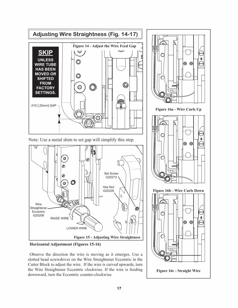
Horizontal Adjustment (Figures 15-16)
Observe the direction the wire is moving as it emerges. Use a slotted head screwdriver on the Wire Straightener Eccentric in the Cutter Block to adjust the wire. If the wire is curved upwards, turn the Wire Straightener Eccentric clockwise. If the wire is feeding downward, turn the Eccentric counter-clockwise.
.010 [.25mm] GAPFigure 16a - Wire Curls Up
Figure 16b - Wire Curls Down
Figure 16c - Straight Wire
Figure 14 - Adjust the Wire Feed Gap
Adjusting Wire Straightness (Fig. 14-17)
Figure 15 - Adjusting Wire Straightness
LOWER WIRE
RAISE WIRE
Note: Use a metal shim to set gap will simplify this step.
Wire Straightener
EccentricG20206
Hex NutG20226
Set ScrewG20273
SKIP UNLESS
WIRE TUBE HAS BEEN MOVED OR
SHIFTED FROM
FACTORY SETTINGS.
18
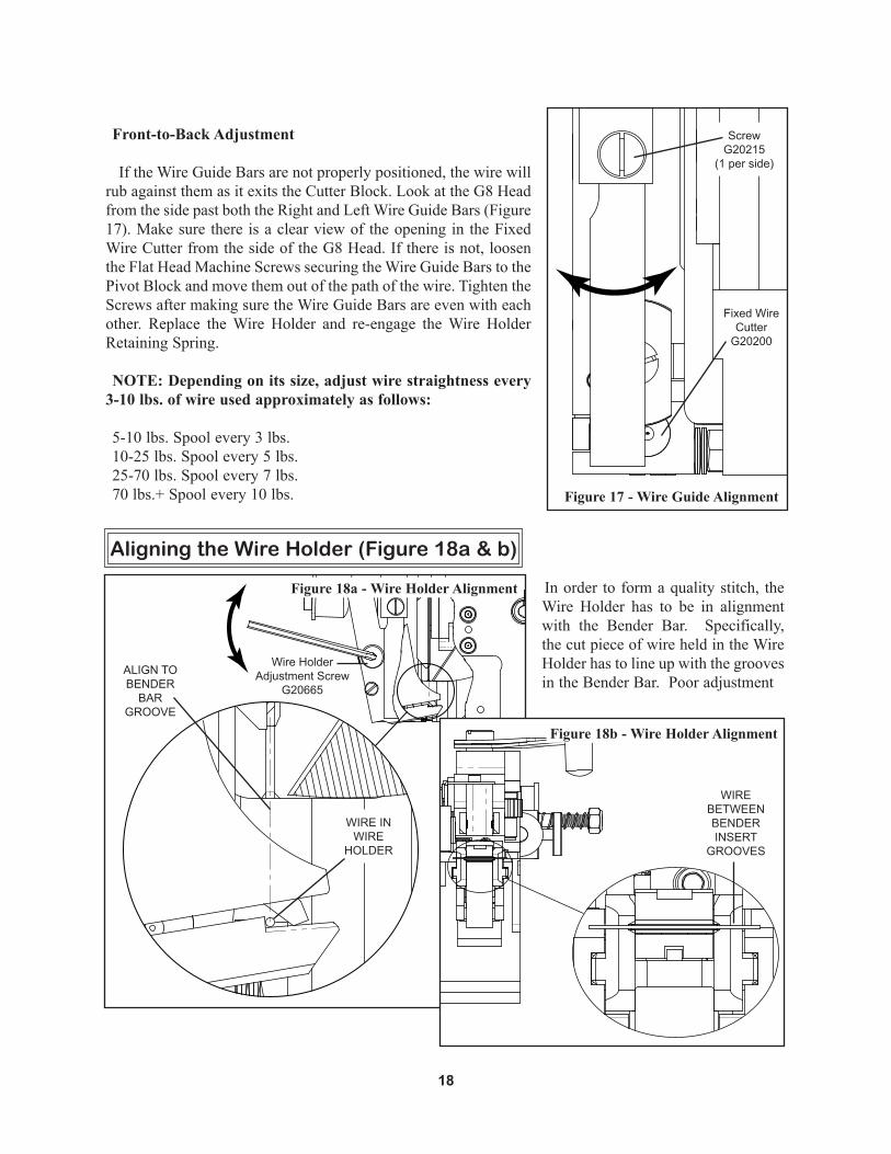
Front-to-Back Adjustment
If the Wire Guide Bars are not properly positioned, the wire will rub against them as it exits the Cutter Block. Look at the G8 Head from the side past both the Right and Left Wire Guide Bars (Figure 17). Make sure there is a clear view of the opening in the Fixed Wire Cutter from the side of the G8 Head. If there is not, loosen the Flat Head Machine Screws securing the Wire Guide Bars to the Pivot Block and move them out of the path of the wire. Tighten the Screws after making sure the Wire Guide Bars are even with each other. Replace the Wire Holder and re-engage the Wire Holder Retaining Spring.
NOTE: Depending on its size, adjust wire straightness every 3-10 lbs. of wire used approximately as follows:
5-10 lbs. Spool every 3 lbs.10-25 lbs. Spool every 5 lbs.25-70 lbs. Spool every 7 lbs.70 lbs.+ Spool every 10 lbs.
In order to form a quality stitch, the Wire Holder has to be in alignment with the Bender Bar. Specifically, the cut piece of wire held in the Wire Holder has to line up with the grooves in the Bender Bar. Poor adjustment
Aligning the Wire Holder (Figure 18a & b)
Figure 17 - Wire Guide Alignment
Fixed Wire Cutter
G20200
ScrewG20215
(1 per side)
WIRE IN WIRE
HOLDER
ALIGN TO BENDER
BAR GROOVE
WIRE BETWEEN BENDER INSERT
GROOVES
Wire Holder Adjustment Screw
G20665
Figure 18a - Wire Holder Alignment
Figure 18b - Wire Holder Alignment

19
may cause broken crowns or other poor stitching.
Load a piece of wire into the Wire Holder. Using a mirror, check to make sure the wire in the Wire Holder is lined up with the grooves in the Bender Bar (Figure 18b). If it is not, loosen the Socket Head Set Screw in the front of the Wire Holder and the Hex Nut (seen in Figure 15) securing the Wire Holder Adjustment Screw (Figure 18a). Turn the Adjustment Screw until the wire is aligned with the grooves in the Bender Bar. Tighten the Hex Nut and Set Screw to secure this setting.
Remove the wire in the Wire Holder and load another piece in the Stitcher Head. Verify that the setting established is accurate by again checking the piece of wire with the mirror.
Before making any adjustments, make sure your stitching machine compression setting is set to the proper thickness of work. Make a few sample stitches and look at the results.
Setting the Stitch Gap (Or Adjusting the Wire Draw)
To adjust the overall length (wire draw) of the stitch, disengage the Small Feed Gear by turning the Feed ReleaseHandle1/4ofaturntotherightasshown.AdjusttheFeedRackAdjustmentKnobuntilthegapbetweenthestaplelegsallowsonlytheedgeofafingernailtopassbetweenthem.
• Toextendthelengthofthestitchordecreasethegap,turntheFeedRackAdjustmentKnobclockwise. (See upper view of Figure A)• To shorten the length of the stitch or increase the gap, turn the knob counter-clockwise. (See lower view of Figure A)
Centering the Stitch Gap (Or Setting Equal Length Legs)
The amount of wire on either side of the stitch gap should be the same. The gap position is controlled by the position of the Cutter Block. As thicker work is stitched, the Cutter Block must be moved further from the Wire Holder to keep the legs of the stitch even and the gap centered.
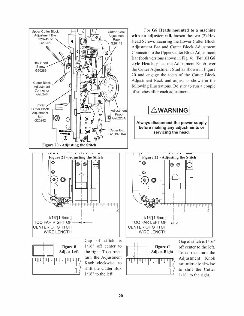
Adjusting the Stitch (Figure 19-23)
RIGHT LEG TOO SHORT
RIGHT LEG TOO LONG
Figure A Adjust Length
Figure 19 - Adjusting the Wire Draw
MORE WIRE DRAW
LESS WIRE DRAW
Feed Rack Adjustment Knob
G20173
20
For G8 Heads mounted to a machine with an adjuster rail, loosen the two (2) Hex Head Screws securing the Lower Cutter Block Adjustment Bar and Cutter Block Adjustment Connector to the Upper Cutter Block Adjustment Bar (both versions shown in Fig. 4). For all G8 style Heads, place theAdjustmentKnob overthe Cutter Adjustment Stud as shown in Figure 20 and engage the teeth of the Cutter Block Adjustment Rack and adjust as shown in the following illustrations. Be sure to run a couple of stitches after each adjustment.
1/16"[1.6mm]TOO FAR LEFT OF
CENTER OF STITCHWIRE LENGTH
1/16"[1.6mm]TOO FAR RIGHT OFCENTER OF STITCH
WIRE LENGTH
Gap of stitch is 1/16" off center to the right. To correct. turn the Adjustment Knob clockwise. toshift the Cutter Box 1/16" to the left.
Gap of stitch is 1/16" off center to the left. To correct. turn the Adjustment Knobcounter-clockwise to shift the Cutter 1/16" to the right.
Figure B Adjust Left
Figure C Adjust Right
Figure 21 - Adjusting the Stitch Figure 22 - Adjusting the Stitch
Figure 20 - Adjusting the Stitch
Hex Head Screw
G20289
Cutter BoxG20197BAA
Lower Cutter Block Adjustment
BarG20242
Cutter Block Adjustment ConnectorG20246
Upper Cutter Block Adjustment Bar
G20245 orG20251
Adjustment Knob
G20228A
Cutter Block Adjustment
RackG20143
Always disconnect the power supply before making any adjustments or
servicing the head.
WARNING!
21
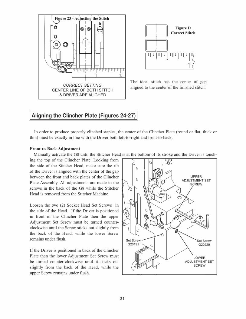
Aligning the Clincher Plate (Figures 24-27)
In order to produce properly clinched staples, the center of the Clincher Plate (round or flat, thick or thin) must be exactly in line with the Driver both left-to-right and front-to-back.
Front-to-Back Adjustment Manually activate the G8 until the Stitcher Head is at the bottom of its stroke and the Driver is touch-ing the top of the Clincher Plate. Looking from the side of the Stitcher Head, make sure the rib of the Driver is aligned with the center of the gap between the front and back plates of the Clincher Plate Assembly. All adjustments are made to the screws in the back of the G8 while the Stitcher Head is removed from the Stitcher Machine.
Loosen the two (2) Socket Head Set Screws in the side of the Head. If the Driver is positioned in front of the Clincher Plate then the upper Adjustment Set Screw must be turned counter-clockwise until the Screw sticks out slightly from the back of the Head, while the lower Screw remains under flush.
If the Driver is positioned in back of the Clincher Plate then the lower Adjustment Set Screw must be turned counter-clockwise until it sticks out slightly from the back of the Head, while the upper Screw remains under flush.
Set ScrewG20229
Set ScrewG20191
LOWER ADJUSTMENT SET
SCREW
CORRECT SETTING.CENTER LINE OF BOTH STITCH
& DRIVER ARE ALIGHED
The ideal stitch has the center of gap aligned to the center of the finished stitch.
Figure D Correct Stitch
Figure 23 - Adjusting the Stitch
UPPER ADJUSTMENT SET
SCREW

22
The position of the Clincher Points should be flush, or slightly above flush, with the Clincher Plate in order to achieve a quality stitch. To ensure this, manually turn the stitcher machine until the Driver is at the lowest position of its stroke and the Clincher Points are at their highest position. Turn the stitcher machine just past this point to reveal the Clincher Points’ position. Clincher Points that do not pivot high enough will produce a weak clinch, where Clincher Points that pivot too high will cause poor stitch quality or cut the stock being stitched.
Adjusting the Clincher Points (Figure 28-29)
Figure 25 - Properly Aligned Figure 26 - Front To Back Alignment
DRIVER TOO FAR BACK, ADJUST
LOWER SET SCREW
DRIVER TOO FAR FORWARD, ADJUST UPPER SET SCREWCENTERED STITCH
Slight adjustments to the Set Screws make significant differences in position. Once the position is set, tighten the two (2) Socket Head Set Screws in the side of the Stitcher Head.
Left-to-Right Looking from the front of the Stitcher Head, make sure the Driver is centered directly above the Clincher Slide (CA9093A or 9084B). If it is not, loosen the two (2) Clincher Plate Nuts and move the entire Clincher Plate Assembly to the right or to the left. Secure this position while tightening the nuts again.
Clincher Plate Nuts
2091
LOOSEN, ADJUST & RETIGHTEN
CORRECTALIGNMENT
Figure 27 - Left to Right Alignment
CLINCHER POINTSTO BE FLUSH OR
JUST ABOVE PLATE
23
Always disconnect the power supply beforemaking any adjustments or servicing the head.
WARNING!
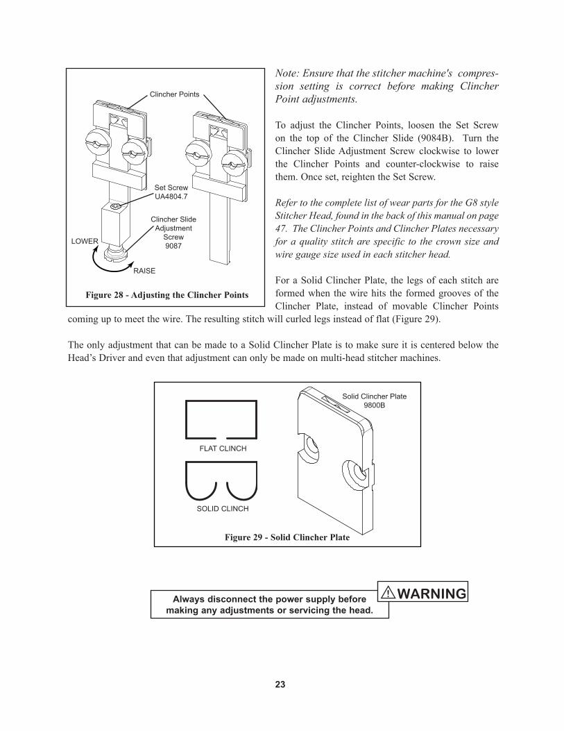
Note: Ensure that the stitcher machine's compres-sion setting is correct before making Clincher Point adjustments.
To adjust the Clincher Points, loosen the Set Screw on the top of the Clincher Slide (9084B). Turn the Clincher Slide Adjustment Screw clockwise to lower the Clincher Points and counter-clockwise to raise them. Once set, reighten the Set Screw.
Refer to the complete list of wear parts for the G8 style Stitcher Head, found in the back of this manual on page 47. The Clincher Points and Clincher Plates necessary for a quality stitch are specific to the crown size and wire gauge size used in each stitcher head.
For a Solid Clincher Plate, the legs of each stitch are formed when the wire hits the formed grooves of the Clincher Plate, instead of movable Clincher Points
coming up to meet the wire. The resulting stitch will curled legs instead of flat (Figure 29).
The only adjustment that can be made to a Solid Clincher Plate is to make sure it is centered below the Head’s Driver and even that adjustment can only be made on multi-head stitcher machines.
Figure 29 - Solid Clincher Plate
SOLID CLINCH
FLAT CLINCH
Figure 28 - Adjusting the Clincher Points
Clincher Points
Set ScrewUA4804.7
Clincher Slide Adjustment
Screw9087LOWER
RAISE
Solid Clincher Plate9800B

24
The Bender Bar Stop is set at the factory. The Stop controls the position of the Bender Bar Latch at the top of the stitcher head’s stroke. If the Latch does not fall within the proper area of the Driver Bar, partially formed stitches will result or the G8 will jam.
The right edge of the Bender Bar Latch should stick out from the Bender Bar at least 3/32” [2.5mm] (Figure 30) when the G8 reaches the top of its stroke. If the Latch does not protrude this far then the Bender Bar Stop Screw is set too high. If the Stop Screw is set too low then the wire will hit the Bender Bar rather than feeding below it for forming.
To adjust, remove the two (2) Screws securing the Pivot Block (with attached components) to remove it from the Feed Gear Bracket (Figure 31). Loosen, but do not remove, securing the Stop Screw. Turn the Stop
Adjusting the Bender Bar Stop (Figures 29-31)
3/32"2.5
Bender Bar Latch
G20149
Figure 30 - Adjusting the Bender Bar Stop
Pivot BlockG20139A
Figure 31 - Removing Pivot Block Assembly
Bender Bar Stop Screw
G20229
Set ScrewG20273 (Hidden)
G20196
G20189

25
Screw clockwise to raise the Bender Bar’s position and counter-clockwise to lower it’s position. The normal position is about 1/8” or 3mm out from the Feed Gear Bracket.
Replace the Pivot Block using its Locating Pins with the holes in the Bonnet. Manually turn the Large Feed Gear (G20110A) if its teeth are not aligned with those on the Feed Rack (G20127). Replace the Screws.
1/8"3
LOWERBENDER BAR
POSITIONRAISEBENDER BAR
POSITION
LOOSEN SET SCREW,ADJUST STOP SCREW,TIGHTEN SET SCREW
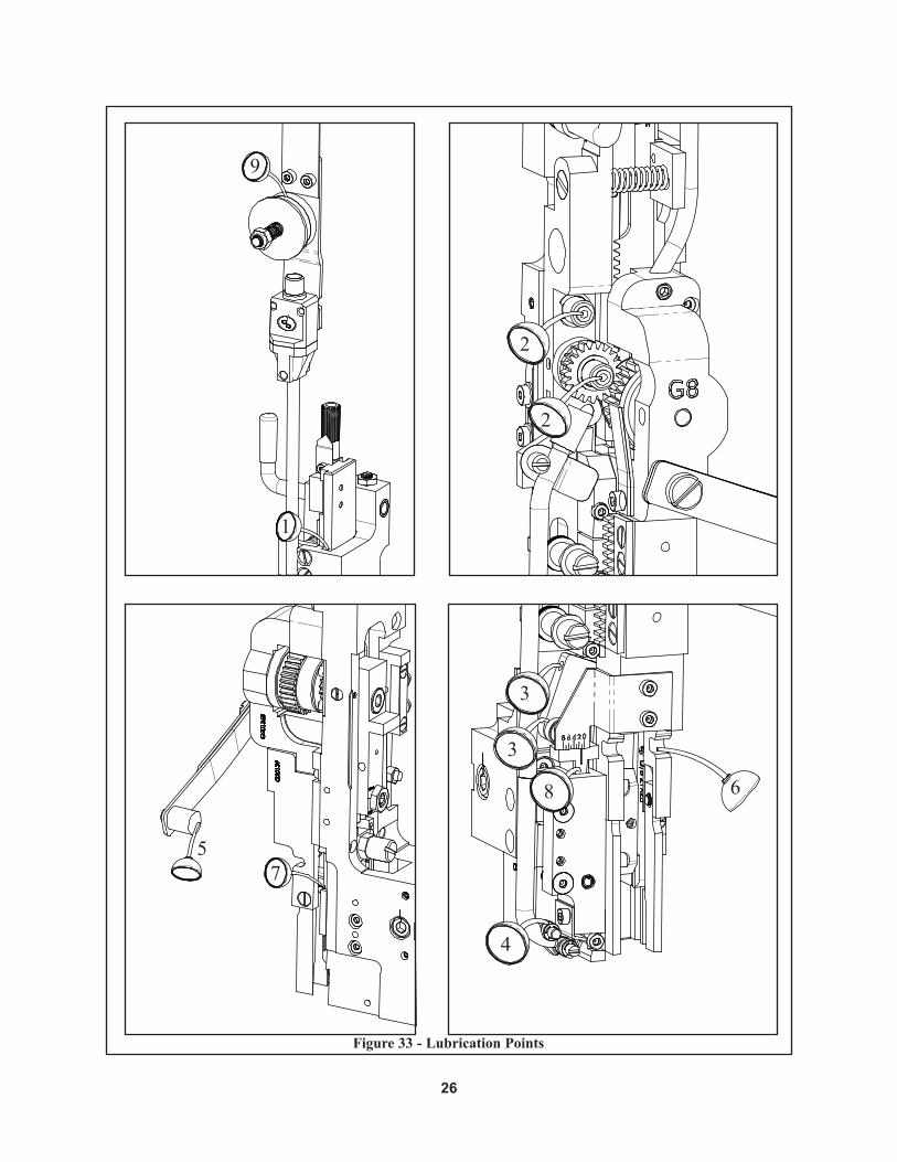
Lubrication (Figure 33)
Use any standard S.A.E. #10 oil for lubricating the heads. Heads that are in constant operation should be lubricated daily. Heads that are operated periodically should be lubricated every five pound wire spool change or every month, which ever comes first. Usually, only a drop of oil is required at each lubrication point. Care must be taken that those parts of the head that contact the work to be stitched are free of oil. Lubricate regularly instead of excessively. Excessive oiling will result in work becoming spotted with oil. Use one drop of oil in the following lubrication points:
1. The top of the Bonnet (G20000A) on either side of the Feed Slide (G20131).
2. The fittings on the Feed Lever Pivot Pin and the Small Feed Gear Pin (G20262A).
3. The Cutter Operating Lever Pivot Pin (G20231) and Roller Pin (G20232).
4. The Wire Straightening Rollers (G20208B) in the Cutter Block Assembly (G20197A).
5. On the Wire Holder Assembly under the Wire Holder Retaining Spring Foot (G20184).
6. Where the Wire Holder Assembly (G20559BA) pivots in the Left and Right Wire Guide Bars (G20141 and G20142).
7. On the Bender Bar Latch (G20149) and the Latch Release Cam (G20115).
8. In the Cutter Block Assembly, along side the Cutter Operating Slide (G20198).
9. In the Wire Felt to saturate it.
Figure 32 - Adjusting the Bender Bar Stop
Maintenance
26
Figure 33 - Lubrication Points
1
2
2
4
3
3
5
6
7
8
9

27
In addition to proper lubrication, routine cleaning is important for the maintenance of your G8 Head. The entire Head should be torn down and rebuilt every three to six months and the following areas should be cleaned once every three months:
•Large Feed Gear (G20110A): remove and wash in an oil-dissolving solvent, like Aeroshell 14 (G20824). Dry and relubricate.
•Anywhere that dust, oil or pieces of wire and paper have built up - for example: around the Clincher Points and around the Wire Straightener Rollers.
Cleaning
Figure 34 - Large Feed Gear
Always power down the stitcher machine before any maintenance or adjustments
are made to the stitcher head.
!CAUTION!

28
In time, you will need to replace some parts in your G8 style Stitcher Head. When this happens, first locate the needed part in one of the following diagrams. Then locate the DeLuxe Stitcher part number and contact your Graphic Arts Representative to order the part by the part number, description and quantity. Customer Service Hotline: 800-634-0810
Ordering Spare Parts
solving your wire stitching needs for 125 years...
29
The quality and quantity of work that can be produced with the G8 Stitcher Head is dependent upon the operator making all adjustments as accurately as possible and carefully maintaining the head. The cause of staple imperfections usually can be traced to inaccurate settings or normal wear of moving parts. In the event of trouble of this nature occurring, the operator can, by referring to the following troubleshooting chart, quickly locate and remedy the cause or causes of the trouble.
The following is a brief list of problems and solutions which should cover the majority of situations encountered when stitching with the G8 Stitching Head. In the event of problems of this nature occurring, the operator can, by referring to the following troubleshooting chart, quickly locate the solutions.
Troubleshooting (Figure 35)

30
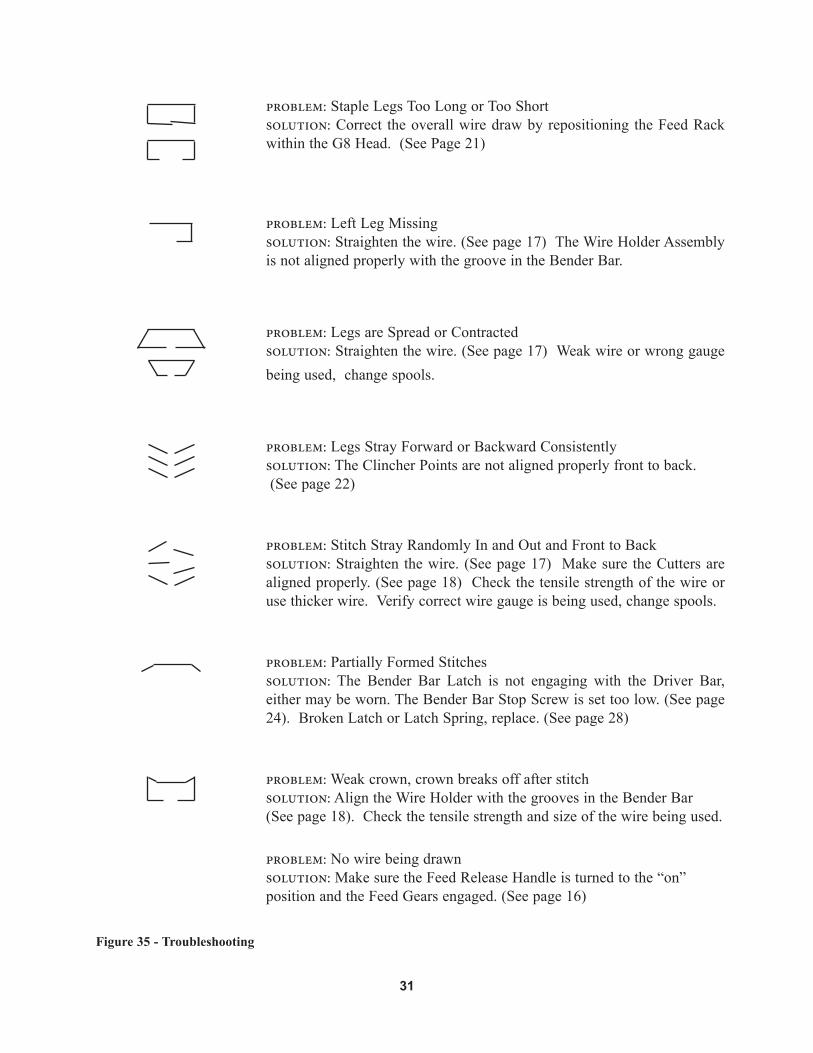
Figure 35 - Troubleshooting
problem: Crown Not Straightsolution: Straighten the wire. (See page 17) Align the Clincher Points. (See page 22) Reverse or replace the worn or broken Driver. (See page 28) Make sure the Cutters are aligned and not dull. (See page 18) Check for correct wire size and strength being used. Check for correct work thickness setting. Check the quality of the wire being used, change spools.
problem: Leg(s) Buckledsolution: If the ends of an unformed piece of wire are not smooth, the Wire Cutters are worn. Check for wear and rotate or replace if needed. (See page 28) Make sure the Cutters are aligned properly. (See page 18) Make sure the correct wire size is being used and that the wire is straight. (See page 17). Check the quality of the wire being used, change spools.
problem: Corner Buckledsolution: Check the Driver for a chipped corner and rotate or replace it if needed. (See page 28) Align the Wire Holder. (See page 18) Check the tensile strength of the wire or use thicker wire.
problem: Clinch Too Loosesolution: The Clincher Points are too low or too high and need adjusting. (See page 22) The compression of the stitcher machine is insufficient and needs to be increased.
problem: Left Leg Too Short / Right Leg Too Longsolution: Adjust the position of the Cutter Block Assembly by moving it away from the Head. (See page 20)
problem: Left Leg Too Long / Right Leg Too Shortsolution: Adjust the position of the Cutter Block Assembly by moving it away toward the Head. (See page 20)
31
problem: Staple Legs Too Long or Too Shortsolution: Correct the overall wire draw by repositioning the Feed Rack within the G8 Head. (See Page 21)
problem: Left Leg Missingsolution: Straighten the wire. (See page 17) The Wire Holder Assembly is not aligned properly with the groove in the Bender Bar.
problem: Legs are Spread or Contractedsolution: Straighten the wire. (See page 17) Weak wire or wrong gauge being used, change spools.
problem: Legs Stray Forward or Backward Consistentlysolution: The Clincher Points are not aligned properly front to back. (See page 22)
problem: Stitch Stray Randomly In and Out and Front to Backsolution: Straighten the wire. (See page 17) Make sure the Cutters are aligned properly. (See page 18) Check the tensile strength of the wire or use thicker wire. Verify correct wire gauge is being used, change spools.
problem: Partially Formed Stitchessolution: The Bender Bar Latch is not engaging with the Driver Bar, either may be worn. The Bender Bar Stop Screw is set too low. (See page 24). Broken Latch or Latch Spring, replace. (See page 28)
problem: Weak crown, crown breaks off after stitchsolution: Align the Wire Holder with the grooves in the Bender Bar(See page 18). Check the tensile strength and size of the wire being used.
problem: No wire being drawnsolution: Make sure the Feed Release Handle is turned to the “on” position and the Feed Gears engaged. (See page 16)
Figure 35 - Troubleshooting
32
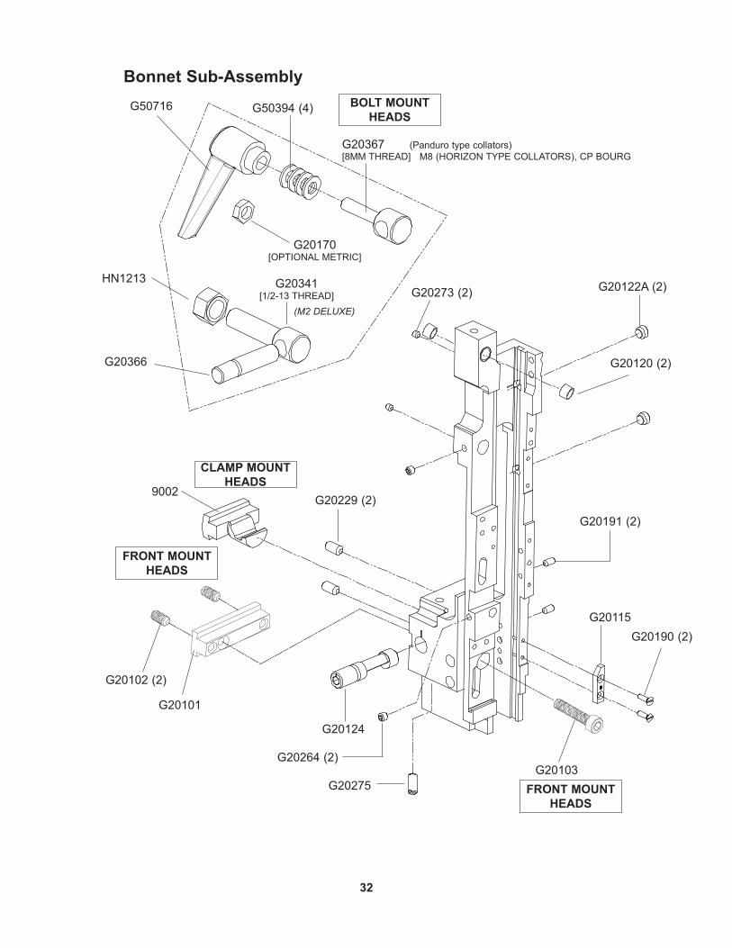
Bonnet Sub-Assembly
G20170[OPTIONAL METRIC]
G20367 (Panduro type collators)[8MM THREAD] M8 (HORIZON TYPE COLLATORS), CP BOURG
HN1213
G20366
G20341[1/2-13 THREAD]
9002
G20124
G20101
G20229 (2)
G20102 (2)
G20273 (2) (M2 DELUXE)
G20275
G20264 (2)
G20115
G20122A (2)
G20191 (2)
G20190 (2)
G20103
CLAMP MOUNTHEADS
BOLT MOUNTHEADS
FRONT MOUNTHEADS
FRONT MOUNTHEADS
G50716 G50394 (4)
G20120 (2)

33
Part Number / Description Cross-Reference
Bonnet Sub-AssemblyG20115 LATCH RELEASE CAM 1G20120 FEED RELEASE BUSHING 2G20122A FEED SLIDE RETAINING SCREW ASY 2G20190 SCREW M3X.5X10- FHMS- SLOTTED 2G20191 SCREW, M4X.7X8 SHSS 2G20229 SCREW, M6X1.0X12, NYLON 2G20264 SCREW M5X.8X5 SHCS 2G20273 SCREW M4X0.7X4 SHSS 2
G20275 BALL SPRING PLUNGER 1
Mount Head Styles
Bolt Mount HeadsG20170 HEX JAM NUT, M8X1.25 1G20341 REAR MOUNTING BOLT, 1/2”-13 1G20366 REAR CLAMP PIN 1G20367 REAR MOUNTING BOLT, 8MM 1G50394 FLAT WASHER - M8 4G50716 MOUNTING BLOCK HANDLE, M8 1HN1213 BONNET STUD NUT, 1/2”-13 1
Front Mount HeadsG20101 FRONT MOUNT BLOCK - G8 1 G20102 SCREW M6X1.0X12, NYLON 2G20103 SCREW M6X1.0X30 1
Clamp Mount Heads9002 BONNET CLAMP BLOCK 1G20124 BONNET CLAMP ECCENTRIC 1
34
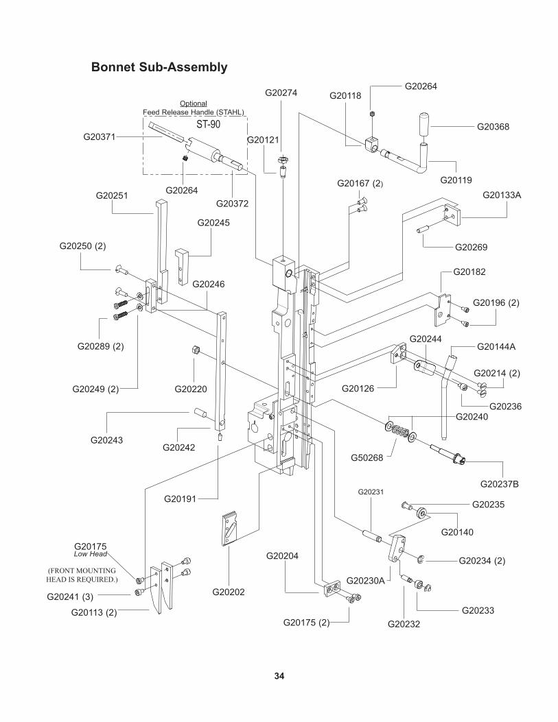
Bonnet Sub-Assembly
G20368
G20264G20118
G20119
G20251
G20245
G20250 (2)
G20289 (2)
G20249 (2)
G20246
G20191
G20243G20242
G20220
G20241 (3)
G20113 (2)
G20175Low Head
G20202
G20121
G20274
G20204
G20175 (2)
G20234 (2)
G20140
G20231
G20230A
G20233G20232
G20235
G20167 (2)
G20237B
G20240
G50268
G20126
G20196 (2)
G20182
G20269
G20133A
G20214 (2)
G20244
G20236
G20144A
G20264
G20371
G20372
Optional Feed Release Handle (STAHL)
(FRONT MOUNTING HEAD IS REQUIRED.)
ST-90

35
G20118 FEED RELEASE HANDLE CAM 1G20119 FEED RELEASE HANDLE 1G20121 FEED RELEASE PLUNGER 1G20126 TUBE PIVOT PLATE 1G20133A FEED RELEASE BLOCK ASSY 1G20140 FOLLOWER BALL BEARING 1G20144A MIDDLE WIRE TUBE ASSEMBLY 1G20167 SCREW, M4X0.7X10 FHCS 2G20175 SCREW M4X.7X6 SHCS 2G20182 FEED GEAR SHAFT PLATE 1G20191 SCREW, M4X.7X8 SHSS 1G20196 SCREW M3X.5X6 SHCS 2G20202 CUTTER BLOCK SLIDE PLATE 1G20204 UPPER CUTTER BLOCK GUIDE 1G20214 SCREW M4X0.7X8 FHMS 2G20220 HEX NUT M5X.8 1G20230A CUTTER OPERATING LEVER ASSY 1G20231 CUTTER OP. LEVER PIVOT PIN 1G20232 CUTTER OP. LEVER ROLL PIN 1G20233 CUTTER OP. ROLLER 1
G20234 E-RING- 3/16" 2G20235 FOLLOWER BEARING SHAFT 1G20236 TUBE PIVOT SCREW 1G20237B ADJUSTMENT STUD 1G20240 ADJUSTMENT WASHER 2G20242 ADJUSTMENT BAR - LOWER 1G20243 DOWEL PIN 1/4X9/16 1G20244 TUBE PIVOT CLIP 1G20245 ADJUSTMENT BAR - UPPER 1G20246 ADJUSTMENT CONNECT 1G20249 CUTTER BLOCK WASHER 2G20250 SCREW M4X.7X14 2G20251 ADJUSTMENT BAR - UPPER 1G20264 SCREW M5X.8X5 SHCS 2G20269 SPIROL PIN 3/16X5/8 1G20274 HEX JAM NUT, M6X1 1G20289 SCREW M4X.7X16 2G20368 FEED RELEASE HANDLE CAP 1G50268 FEED LEVER SPRING 1
Bonnet Sub-Assembly
Optional Feed Release Handle (STAHL)
G20371 FEED RELEASE HANDLE 1G20372 FEED RELEASE SHAFT 1G20264 SCREW M5X.8X5 SHCS 1
Front Mounting HeadsG20113 SUPPORTER GUIDE PLATE 2G20175 SCREW M4X.7X6 SHCS 1G20241 SCREW M4X0.7X6 SHCS 3
36
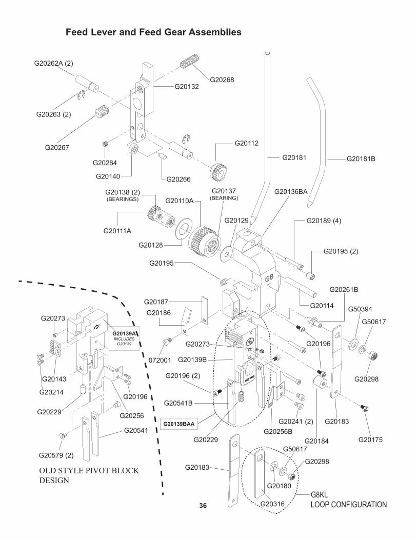
Feed Lever and Feed Gear Assemblies
G20268
G20112
G20262A (2)
G20263 (2)
G20132
G20264
G20266G20140
G20267
G20111A
G20128
G20195
G20110A
G20129
G20181
G20541B
G20241 (2)
G20229
G20196 (2)
G20256B
072001
G20189 (4)
G20195 (2)
G50617
G20114
G20298
G20316
G20175G20184
G20183
G20186G20187
G20138 (2)(BEARINGS)
G20136BA
G20273
G20137(BEARING)
G20181B
G20180
G20261B
G20541
G20579 (2)
G20214
G20143
G20229
G20196
G20256
G20273
G20139AINCLUDES
G20139
OLDSTYLEPIVOTBLOCKDESIGN
G20139BAA
G20139B
G20196
G50394
G8KLLOOP CONFIGURATION
G50617
G20298G20183

37
72001 SCREW M4X0.7X8 1G20110A LARGE FEED GEAR ASSEMBLY 1G20111A FEED PINION ASSEMBLY 1G20114 FEED PINION SHAFT 1G20128 LARGE FEED GEAR WASHER 1G20129 SMALL FEED GEAR WASHER 1G20136BA FEED GEAR BRACKET ASSEMBLY 1G20137 ROLLER CLUTCH BEARING 1G20138 FEED PINION BEARING 2G20139BAA PIVOT BLOCK ASSEMBLY COMPLETE - G8 1G20175 SCREW M4X0.7X6 SHCS 1G20180 FLAT WASHER M6 1G20181 UPPER WIRE TUBE 1G20181B UPPER WIRE TUBE, G8 STITCHEMASTER 1G20183 WIRE HOLDER RETAINING SPRING - LONG 1G20184 WIRE HOLDER RETAINING SPRING FOOT 1G20186 FEED GEAR FRICTION SPRING 1G20187 FEED GEAR FRICTION STRIP 1G20189 SCREW M3X.5X20 3G20195 SET SCREW M6X1X8 2G20196 SCREW M3X0.5X6 SHCS 4G20241 M4X0.7X6MM SOCKET HEAD CAP SCREW 2G20256B CUTTER BLOCK SCALE 1G20261B WIRE HOLDER SPRING STUD 1G20298 NYLOCK LOCK NUT, M6X1 1G20316 WIRE HOLDER SPRING - SHORT 1G20579 SCREW, M4X0.7X6-FHM-SLOTTED 2
Feed Gear Assembly
G20139A Replaced By G20139BAG20139 PIVOT BLOCK INSERT, 1/2” CROWN 1G20143 ADJUSTMENT RACK 1G20196 SCREW M3X.5X6 SHCS 2G20214 SCREW M4X0.7X8 FHMS 2G20229 SCREW, M6X1.0X12, NYLON 1G20256 CUTTER BLOCK SCALE, G8 1G20273 SCREW M4X.7X4 SHSS 1G20541 WIRE GUIDE BAR, LEFT 2G20579 SCREW M4X0.7X6 2
Feed Lever AssemblyG20112 SMALL FEED GEAR 1G20132 FEED LEVER 1G20140 FOLLOWER BALL BEARING 1G20262A FEED LEVER PIN ASSEMBLY 2G20263 FEED LEVER E-RING 2G20264 SCREW M5X.8X5 SHCS 1G20266 FOLLOWER BEARING PIN 1G20267 FEED LEVER BUSHING 1G20268 FEED LEVER SPRING 1

38
Driving and Feed Slide Assemblies
G20131
G20127
G20174
G20264
G20176 (2)
G20173
G20179
G20177
G20164B
G20171
G20165
G20162
G20170
G20169B
G20163A
G20167 G20164B
G20171
G20165
G20320
G20321
G20170
G20163AG20167
G20340
For rail-driven Heads For crank-driven Heads
G20130
G20162BAComplete Assembly
G20340(OLD STYLE)
G20320AComplete Assembly

39
Feed Slide Sub-Assemblies
G20162BA Driving Slide AssemblyG20162 DRIVING SLIDE 1G20163A CUTTER OPERATING RAMP ASSEMBLY 1G20164B DRIVING SIDE PLUNGER 1G20165 DRIVING SLIDE SPRING 1G20167 SCREW, M4X0.7X10 FHCS 2G20169B DRIVING SLIDE PLUNGER SCREW ECCENTRIC 1G20170 HEX JAM NUT M8X1.25 1G20171 SCEW, M8X1.25X12 1
G20320A Driving Slide Assembly - Crank DriveG20163A CUTTER OPERATING RAMP ASSEMBLY 1G20164B DRIVING SIDE PLUNGER 1G20165 DRIVING SLIDE SPRING 1G20167 SCREW, M4X0.7X10 FHCS 2G20170 HEX JAM NUT M8X1.25 1G20171 SCEW, M8X1.25X12 1G20320 DRIVING SLIDE - CRANK DRIVE 1G20321 CRANK LINK SCREW 1G20163A CUTTER OPERATING RAMP ASSEMBLY 1
Driving Slide AssemblyG20127 FEED RACK 1G20130 FEED ADJUSTMENT BLOCK 1G20131 FEED SLIDE 1G20173 FEED RACK KNOB - KNURLED 1G20174 FEED RACK ADJUSTMENT STUD 1G20176 SCREW M4X.7X12 SHCS LOW HEAD 2G20177 FEED RACK ADJ KNOB POINTER 1G20179 SCREW M3X.5X4, SHCS 1G20264 SCREW M5X.8X5 SHCS 1G20340 CRANK DRIVE LINK 1
40
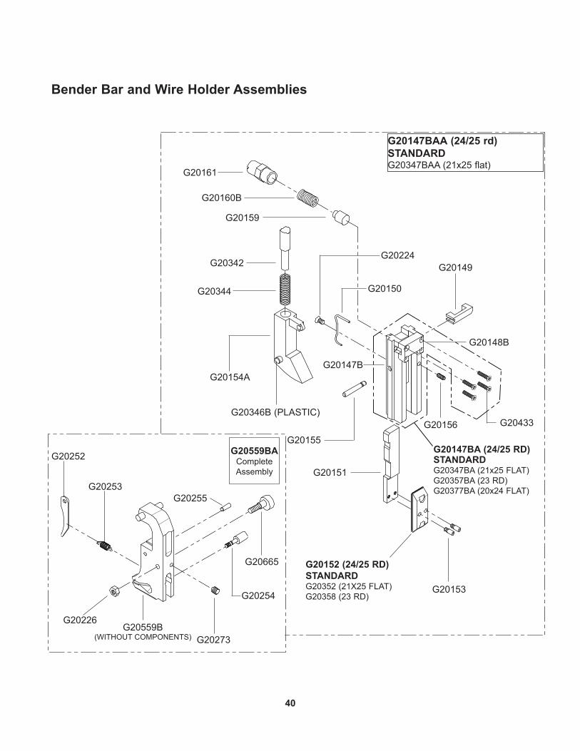
Bender Bar and Wire Holder Assemblies
G20160B
G20161
G20159
G20344
G20342
G20154A
G20152 (24/25 RD) STANDARDG20352 (21X25 FLAT)G20358 (23 RD)
G20153
G20151
G20149
G20155
G20150
G20224
G20433 G20156
G20273
G20252
G20226
G20148B
G20147BAA (24/25 rd) STANDARDG20347BAA (21x25 flat)
G20254
G20253
G20559B(WITHOUT COMPONENTS)
G20665
G20255
G20346B (PLASTIC)
G20559BAComplete Assembly
G20147B
G20147BA (24/25 RD) STANDARDG20347BA (21x25 FLAT)G20357BA (23 RD)G20377BA (20x24 FLAT)
41
G20147BAA Bender Bar/Driver Assembly (24/25 RD) STANDARD
G20147BA BENDER BAR ASSEMBLY, 24W 1G20149 BENDER BAR LATCH 1G20150 BENDER BAR LATCH SPRING 1G20151 DRIVER BAR 1G20152 DRIVER, 24W 1G20153 DRIVER RETAINING SCREW 2G20154A SUPPORTER ASSEMBLY 1G20155 SUPPORTER PIVOT PIN 1G20156 SUPPORTER PIVOT PIN SCREW 1G20159 BENDER BAR FRICTION PLUG 1G20160B BENDER BAR FRICTION SPRING 1G20161 BENDER BAR FRICTION BUSHING 1G20224 BENDER BAR LATCH SPRING SCREW 1G20342 SUPPORTER SPRING PLUNGER 1G20344 SUPPORTER SPRING 1
G20347BAA Bender Bar/Driver Assembly (21x25 Wire) G20347BA BENDER BAR ASSEMBLY, 21X25W 1
G20377BA Bender Bar Assembly (20x24 Flat)G20148B LATCH HOUSING, REMOVABLE 1G20377B BENDER BAR, 20X24 WIRE 1G20433 SCREW, M2.5X.45X12 4
G20599BA Wire Holder Assembly 1/2 CrG20226 HEX NUT M4X.7 1G20252 WIRE HOOK 1G20253 WIRE HOOK SPRING 1G20254 WIRE HOOK SPRING SCREW 1G20255 HOOK PIVOT PIN 1G20273 SCREW M4X0.7X4 SHSS 1G20559B WIRE HOLDER 1/2 CR 1G20665 WIRE HOLDER ECCENTRIC SCREW 1
G20357BAA Bender Bar/Driver Assembly (21x25 Wire) G20357BA BENDER BAR ASSEMBLY, 23W 1G20358 DRIVER, 23W 1
42
APPLY BLUE LOCTITETO THREADS
APPLY GREASE
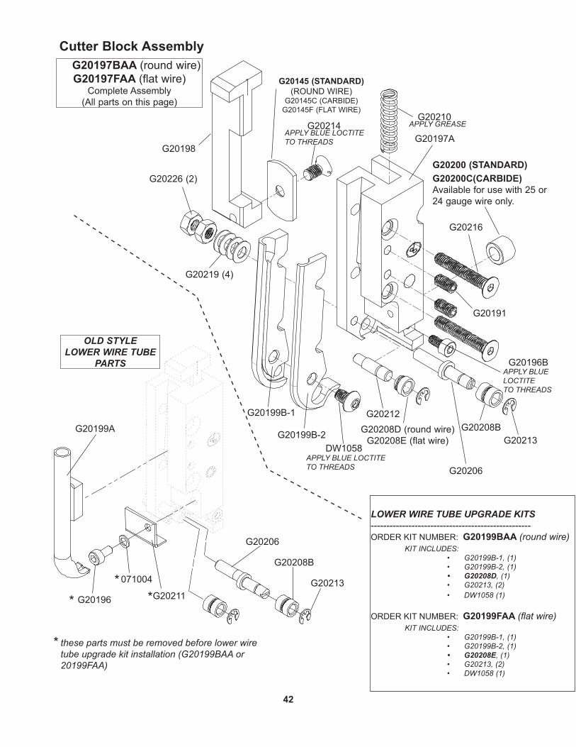
Cutter Block Assembly
LOWER WIRE TUBE UPGRADE KITS---------------------------------------------------ORDER KIT NUMBER: G20199BAA (round wire)
KIT INCLUDES:• G20199B-1, (1)• G20199B-2, (1)• G20208D, (1)• G20213, (2)• DW1058 (1)
ORDER KIT NUMBER: G20199FAA (flat wire)KIT INCLUDES:
• G20199B-1, (1)• G20199B-2, (1)• G20208E, (1)• G20213, (2)• DW1058 (1)
OLD STYLE LOWER WIRE TUBE
PARTS G20196BAPPLY BLUE LOCTITETO THREADS
APPLY BLUE LOCTITETO THREADS G20206
G20210
G20191
G20197AG20198
G20214
G20219 (4)
G20226 (2)
G20197BAA (round wire) G20197FAA (flat wire)
Complete Assembly(All parts on this page)
G20216
G20208B
G20213
G20212G20199A
G20196
G20199B-1
G20208D (round wire) G20208E (flat wire)
DW1058
G20206
G20208B
G20213
G20199B-2
G20211
071004
*
**
*
these parts must be removed before lower wire tube upgrade kit installation (G20199BAA or 20199FAA)
G20145 (STANDARD) (ROUND WIRE)
G20145C (CARBIDE) G20145F (FLAT WIRE)
G20200 (STANDARD)G20200C(CARBIDE) Available for use with 25 or 24 gauge wire only.

43
Lower Wire Tube Assembly, G8 Round Wire, Upgrade KitsG20199BAA (ROUND WIRE)
G20199FAA (FLAT WIRE)
Cutter Block Assembly G20197BAA (ROUND WIRE)
G20197FAA (FLAT WIRE)Complete Assembly
(All parts on this page)
DW1058 SCREW, M4 X 6, BUTTON HEAD 1G20145 MOVING CUTTER-RND WIRE (STANDARD) 1G20145C MOVING CUTTER - (CARBIDE)G20145F MOVING CUTTER - (FLAT WIRE)G20191 SCREW, M4X.7X8 SHSS 2G20196 SCREW M3X.5X6 SHCS (OLD STYLE) 1G20196B SCREW M3X.5X6 SHCS 1G20197A CUTTER BOX ASEMBLY 1G20198 CUTTER OPERATING SLIDE 1G20199A LOWER WIRE TUBE ASSEMBLY (OLD) 1G20200 FIXED WIRE CUTTER (STANDARD) 1G20200C FIXED CUTTER - (CARBIDE) G20206 WIRE STRAIGHTENER ECCENTRIC 1G20208B WIRE STRAIGHTENER ROLLER 1G20210 CUTTER OPERATING SPRING 1G20214 SCREW M4X0.7X8 FHMS 1G20216 SCREW, M4 X 0.7 X 25 2G20219 WIRE STRAIGHTENER DISC SPRING 4G20226 HEX NUT M4X.7 2G20211 CUTTER WIRE SHIELD (OLD STYLE) 1G20212 WIRE STRAIGHTENER ROLL STUD 1
071004 LOCK WASHER, M3 (OLD STYLE) 1G20199B-1 LOWER WIRE TUBE BASE, G8 1G20199B-2 LOWER WIRE TUBE COVER, G8 1G20213 WIRE STRAIGHTENER ROLL CLIP 2G20208D WIRE STRAIGHTENER ROLLER UPPER, ROUND 1G20208E WIRE STRAIGHTENER ROLLER UPPER, FLAT 1

44
Wire Guide Bracket, Spring and Clincher Plate
G20286A
G20297
G20241 (2)
G20293 (2)
G20293B
G20287G20298
CA9083A (STANDARD)(FOR ROUND WIRE.)9083C (FOR FLAT WIRE.)
7257B ROUND WIRE (STANDARD)7024B FLAT WIRE
7253A
9086A (STANDARD)
CT9093A (STANDARD)9087
CA2091 (2)
9084B
CT9088 (2)
UA4808.7
G20679A
G20279A
G50286SA(FOR USE ON
STITCHMASTER)
G50808
9086JA 9086TAG50710 (2) G50710 (2)
OPTIONAL OPTIONAL
G50800CA
G20288 (2)
18186
38
UA3216.2
18182
18184
18183
FOR M2
G50806G20292
USED ON M MACHINE
G20288
G20293B
G20293
G20292
NOTE: GUIDE SPRING REVERSED.
G20292
G20293

45
38 CLINCHER SLIDE ADJUSTMENT SCREW 19087 CLINCHER SLIDE ADJUSTING SCREW 1
18182 CLINCHER SLIDE 118183 CLINCHER SLIDE ADJUSTMENT BLOCK 118184 CLINCHER SLIDE BLOCK CLAMP 118186 CLINCHER SLIDE ADJUSTMENT SCREW 17024B CLINCHER POINT - FLAT 27253A CLINCHER PLATE ASSEMBLY - 1/2 17257B CLINCHER POINT - ROUND (STANDARD) 29083C CLINCHER POINT - 20X24, FLAT 29084B ADJUSTABLE CLINCHER SLIDE 19086A CLINCHER PLATE - THICK (STANDARD) 19086JA CLINCHER PLATE - THICK 19086TA CLINCHER PLATE, THICK 1CA2091 CLINCHER PLATE BINDER NUT 2CA9083A CLINCHER POINT - (STANARD) 2 CT9088 CLINCHER PLATE BINDER BOLT 2CT9093A CLINCHER SLIDE - THICK (STANDARD) 1 G20241 SCREW M4X0.7X6 SHCS 2G20287 WIRE OILER FELT SPRING 1G20288 SCREW, M4X.7X8 SHCS 2G20292 WIRE OIL FELT WASHER 1G20293 WIRE OILER FELT 2G20293B WIRE OILER FELT, THIN 1G20297 SCREW, M6X1X40 SHCS 1G20298 NYLOCK LOCK NUT, M6X1 1G50710 CLINCHER PLATE NUT 2G50800CA ANTI-WIRE BACKUP UNIT 1G50806 FELT MOUNTING BRACKET 1G50808 WIRE SPRING GUIDE CLAMP PLATE 1UA3216.2 CLINCHER SLIDE BLOCK SCREW 2
UA4808.7 SET SCREW, 1/4-28X1/2", SH 1
ONE OF THE FOLLOWING:
G20279A GUIDE SPRING ASSEMBLY - MEDIUM G20286A GUIDE SPRING ASSEMBLY - LONG G20679A GUIDE SPRING ASSEMBLY - SHORT G50286SA GUIDE SPRING ASSEMBLY - STITCHMASTER
Wire Guide Bracket, Spring and Clincher Plate Assemblies
46
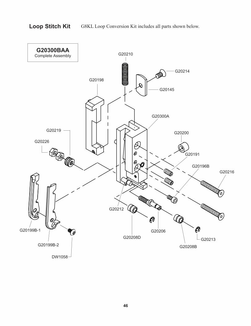
Loop Stitch Kit G8KLLoopConversionKitincludesallpartsshownbelow.
G20210
G20200
G20300A
G20208D G20213
G20212
G20196B
G20206
G20198
G20145
G20214
G20219
G20226
G20191
G20216
G20199B-1
G20199B-2 G20208B
DW1058
G20300BAAComplete Assembly
47
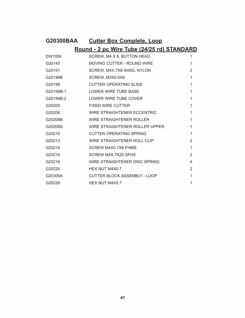
DW1058 SCREW, M4 X 6, BUTTON HEAD 1
G20145 MOVING CUTTER - ROUND WIRE 1
G20191 SCREW, M4X.7X8 SHSS, NYLON 2
G20196B SCREW, M3X0.5X6 1
G20198 CUTTER OPERATING SLIDE 1
G20199B-1 LOWER WIRE TUBE BASE 1
G20199B-2 LOWER WIRE TUBE COVER 1
G20200 FIXED WIRE CUTTER 1
G20206 WIRE STRAIGHTENER ECCENTRIC 1
G20208B WIRE STRAIGHTENER ROLLER 1
G20208D WIRE STRAIGHTENER ROLLER UPPER 1
G20210 CUTTER OPERATING SPRING 1
G20213 WIRE STRAIGHTENER ROLL CLIP 2
G20214 SCREW M4X0.7X8 FHMS 1
G20216 SCREW M4X.7X25 SFHS 2
G20219 WIRE STRAIGHTENER DISC SPRING 4
G20226 HEX NUT M4X0.7 2
G20300A CUTTER BLOCK ASSEMBLY - LOOP 1
G20226 HEX NUT M4X0.7 1
G20300BAA Cutter Box Complete, Loop Round - 2 pc Wire Tube (24/25 rd) STANDARD

48
G20160B
G20161
G20159
G20344W
G20342
G20314(25 Round)
G20153 (2)
G20151
G20149
G20155
G20150
G20224
G20156
G20346B
G20147BA
G20313A
G20317AAComplete Assembly

49
G20147BA BENDER BAR ASSEMBLY, 24W 1
G20149 BENDER BAR LATCH 1
G20150 BENDER BAR LATCH SPRING 1
G20151 DRIVER BAR 1
G20153 DRIVER RETAINING SCREW 2
G20155 SUPPORTER PIVOT PIN 1
G20156 SUPPORTER PIVOT PIN SCREW 1
G20159 BENDER BAR FRICTION PLUG 1
G20160B BENDER BAR FRICTION SPRING 1
G20161 BENDER BAR FRICTION BUSHING 1
G20224 SCREW M3 X 0.5 X 6 1
G20313A SUPPORTER ASSEMBLY - LOOP 1
G20314 DRIVER - LOOP 1
G20342 SUPPORTER SPRING PLUNGER 1
G20346B SUPPORTER GUIDE PIN, COMPOSITE 1
G20344W SUPPORTER SPRING - WATKISS 1
G20317AA Bender/Driver Assembly, Loop
50
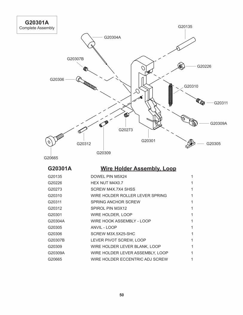
G20301A Wire Holder Assembly, LoopG20135 DOWEL PIN M5X24 1G20226 HEX NUT M4X0.7 1G20273 SCREW M4X.7X4 SHSS 1G20310 WIRE HOLDER ROLLER LEVER SPRING 1G20311 SPRING ANCHOR SCREW 1G20312 SPIROL PIN M3X12 1G20301 WIRE HOLDER, LOOP 1G20304A WIRE HOOK ASSEMBLY - LOOP 1G20305 ANVIL - LOOP 1G20306 SCREW M3X.5X25-SHC 1G20307B LEVER PIVOT SCREW, LOOP 1G20309 WIRE HOLDER LEVER BLANK, LOOP 1G20309A WIRE HOLDER LEVER ASSEMBLY, LOOP 1G20665 WIRE HOLDER ECCENTRIC ADJ SCREW 1
G20305G20312
G20226
G20309A
G20306
G20665G20309
G20135
G20273
G20304A
G20311
G20310
G20301AComplete Assembly
G20301
G20307B
51
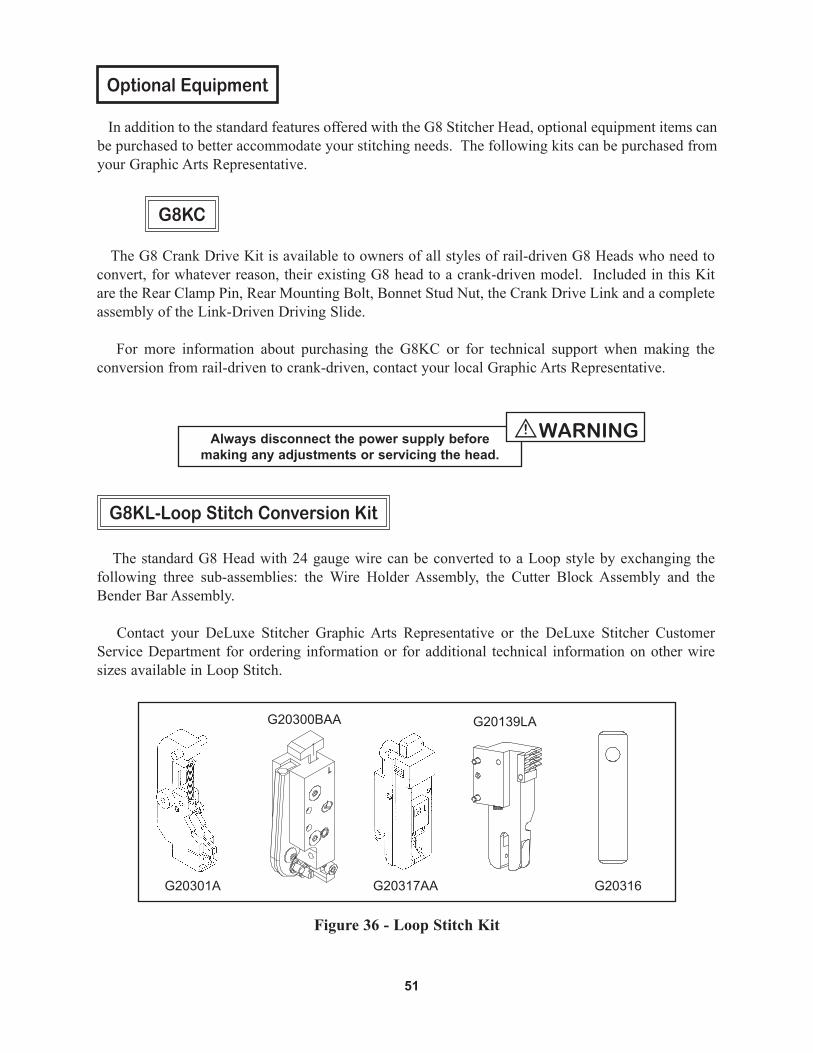
Optional Equipment
In addition to the standard features offered with the G8 Stitcher Head, optional equipment items can be purchased to better accommodate your stitching needs. The following kits can be purchased from your Graphic Arts Representative.
TheG8CrankDriveKitisavailabletoownersofallstylesofrail-drivenG8Headswhoneedtoconvert,forwhateverreason,theirexistingG8headtoacrank-drivenmodel.IncludedinthisKitare the Rear Clamp Pin, Rear Mounting Bolt, Bonnet Stud Nut, the Crank Drive Link and a complete assembly of the Link-Driven Driving Slide.
For more information about purchasing the G8KC or for technical support when making theconversion from rail-driven to crank-driven, contact your local Graphic Arts Representative.
G8KC
The standard G8 Head with 24 gauge wire can be converted to a Loop style by exchanging the following three sub-assemblies: the Wire Holder Assembly, the Cutter Block Assembly and the Bender Bar Assembly.
Contact your DeLuxe Stitcher Graphic Arts Representative or the DeLuxe Stitcher Customer Service Department for ordering information or for additional technical information on other wire sizes available in Loop Stitch.
G8KL-Loop Stitch Conversion Kit
G20317AAG20301A
G20300BAA
Figure 36 - Loop Stitch Kit
Always disconnect the power supply beforemaking any adjustments or servicing the head.
WARNING!
G20139LA
G20316

52
TheG8KSmountsontheAdjustmentRailofMcCainSaddleStitchers.Itstopsthefeedingofwirethrough the Stitcher Heads by pushing open the Feed Release Handles (stopping the stitch) when it receives a signal from the calipers of the Stitcher.
TheG8KS Stop StitchKit comes complete with all the components necessary for convertingyour existing stitcher machine, along with fully illustrated instructions. Call your Graphic Arts Representative for more information.
G8KS-Stop Stitch Kit
TheG8KTisaStopStitchToggleKitspecificallydesignedforusersofMcCainStitchersusingboth26/26D and G8 Stitcher Heads.
The Electrical Box, Box Cover and Toggle Switch replace your machine’s existing equipment to makeswitchingbetweenthetwostylesofStitcherHeadseasier.ThisKitcomescompletewithawir-ing diagram and replacement electrical box. For more information or technical support, contact your local Graphic Arts Representative.
G8KT-Stop Stitch Toggle Kit
Always disconnect the power supply beforemaking any adjustments or servicing the head.
WARNING!

53
Part Number / Description Cross-Reference
072001 Screw M4x0.7x8 1
071004 Lock Washer, M3 1
18182 Clincher Slide 1
18183 Clincher Slide Adjustment Block 1
18184 Clincher Slide Block Clamp 1
18186 Clincher Slide Adjustment Screw 1
CA2091 Clincher Plate Binder Nut 2
38 Clincher Slide Adjustment Screw 1
7024B Clincher Point - Flat 2
7253A Clincher Plate Assembly - 1/2 1
7257B Clincher Point - Round 2
9002 Bonnet Clamp Block 1
CA9083A Clincher Point - Thick, Round 2
9083C Clincher Point - 20x24, Flat 2
9084B Adjustable Clincher Slide 1
9086A Clincher Plate - Thick 1
9086JA Clincher Plate - Thick 1
9087 Clincher Slide Adjusting Screw 1
CT9088 Clincher Plate Binder Bolt 2
CT9093A Clincher Slide - Thick 1
G20000A Bonnet Assembly - G8 1
G20110A Large Feed Gear Assembly 1
G20111A Feed Pinion Assembly 1
G20112 Small Feed Gear 1
G20113 Supporter Guide Plate 2
G20114 Feed Pinion Shaft 1
G20115 Latch Release Cam 1
G20118 Feed Release Handle Cam 1
G20119 Feed Release Handle 1
G20121 Feed Release Plunger 1
G20122A Feed Slide Retaining Screw Asy 2
G20124 Bonnet Clamp Eccentric 1
G20126 Tube Pivot Plate 1
G20127 Feed Rack 1
G20128 Large Feed Gear Washer 1
G20129 Small Feed Gear Washer 1
G20130 Feed Adjustment Block 1
G20131 Feed Slide 1
G20132 Feed Lever 1
G20133A Feed Release Spring Block Assembly 1
G20135 Dowel Pin M5x24 1
G20136BA Feed Gear Bracket Assembly 1
G20137 Roller Clutch Bearing 1
G20138 Feed Pinion Bearing 2
G20139 Pivot Block Insert 1
G20139LA Pivot Block Assembly, G8 Loop Optional
G20140 Follower Ball Bearing 1
G20143 Cutter Block Adjustment Rack 1
G20144A Middle Wire Tube Assembly 1
G20145 Moving Cutter - Round Wire 1
G20145C Moving Cutter - Carbide 1
G20145F Moving Cutter - Flat Wire 1
G20147BA Bender Bar Assembly, 24W 1
G20148B Latch Housing, Removable 1
G20149 Bender Bar Latch 1
G20150 Bender Bar Latch Spring 1
G20151 Driver Bar 1
G20152 Driver, 24W 1
G20153 Driver Retaining Screw 2
G20154A Supporter Assembly 1
G20155 Supporter Pivot Pin 1
G20156 Supporter Pivot Pin Screw 1
G20159 Bender Bar Friction Plug 1
G20160B Bender Bar Friction Spring 1
G20161 Bender Bar Friction Bushing 1
G20162 Driving Slide 1
G20162BA Driving Slide Assembly Eccentric 1
G20163A Cutter Operating Ramp Assembly 1
G20164B Driver Slide Plunger Eccentric 1
G20165 Driving Slide Spring 1
G20167 Screw, M4x.7x10 FHCS 4
G20169B Driving Slide Plunger Screw Ecc 1

54
G20171 Screw M8x1.25x12 1
G20173 Feed Rack Knob - Knurled 1
G20174 Feed Rack Adjustment Stud 1
G20175 Screw M4x.7x6 SHCS 3
G20176 Screw M4x.7x12 SHCS Low Head 2
G20177 Feed Rack Adj Knob Pointer 1
G20179 Screw M3x.5x4, SHCS 1
G20180 Flat Washer M6 1
G20181 Upper Wire Tube 1
G20182 Feed Gear Shaft Plate 1
G20183 Wire Holder Retaining Spring - Long 1
G20184 Wire Holder Retaining Spring Foot 1
G20186 Feed Gear Friction Spring 1
G20187 Feed Gear Friction Strip 1
G20188 Dowel Pin, 1/8"x3/8" 4
G20189 Screw M3x.5x20 3
G20190 Screw M3x.5x10- FHMS- Slotted 4
G20191 Screw, M4x.7x8 SHSS 5
G20195 Set Screw M6x1x8 2
G20196 Screw M3x.5x6 SHCS 8
G20197A Cutter Block Assembly 1
G20198 Cutter Operating Slide 1
G20199A Lower Wire Tube Assembly 1
G20199B-1 Lower Wire Tube Base 1
G20199B-2 Lower Wire Tube Cover 1
G20200 Fixed Wire Cutter 1
G20202 Cutter Block Slide Plate 1
G20204 Upper Cutter Block Guide 1
G20206 Wire Straightener Eccentric 1
G20208B Wire Straightener Roller 2
G20208D Wire Straightener Roller Upper, Rd Wire 2
G20210 Cutter Operating Spring 1
G20211 Cutter Wire Shield 1
G20212 Wire Straightener Roll Stud 1
G20213 Wire Straightener Roll Clip 2
G20214 Screw M4x0.7x8 FHMS 5
G20216 Screw M4x.7x25 SFHS 2
G20217 Spirol Pin M5x12 1
G20219 Wire Straightener Disc Spring 4
G20220 Hex Nut M5x.8 1
G20223 Dowel Pin 1/8x1/4 1
G20224 Bender Bar Latch Spring Screw 1
G20226 Hex Nut M4x.7 2
G20228A Adjustment Handle Assembly 1
G20229 Set Screw M6x1x12 2
G20230A Cutter Operating Lever Assembly 1
G20231 Cutter Operating Lever Pivot Pin 1
G20232 Cutter Operating Lever Roll Pin 1
G20233 Cutter Operating Lever Roller 1
G20234 E-Ring- 3/16" 1
G20235 Follower Bearing Shaft 1
G20236 Tube Pivot Screw 1
G20237B Cutter Block Adjustment Stud 1
G20240 Cutter Block Adjustment Washer 2
G20241 Screw M4x0.7x6 SHCS 4
G20242 Cutter Adjustment Bar - Lower 1
G20243 Dowel Pin 1/4x9/16 1
G20244 Tube Pivot Clip 1
G20245 Cutter Adjustment Bar - Upper 1
G20246 Cutter Block Adjustment Connect 1
G20249 Cutter Block Washer 2
G20250 Screw M4x.7x14 2
G20251 Cutter Adjustment Bar - Upper 1
G20252 Wire Hook 1
G20253 Wire Hook Spring 1
G20254 Wire Hook Spring Screw 1
G20256 Cutter Block Scale 1
G20261B Wire Holder Spring Stud 1
G20262A Feed Lever Pin Assembly 2
G20263 Feed Lever E-Ring 2
G20264 Screw M5x.8x5 SHCS 5
G20266 Follower Bearing Pin 1

G20267 Feed Lever Bushing 1
G20268 Feed Lever Spring 1
G20269 Spirol Pin 3/16x5/8 1
G20273 Screw M4x.7x4 SHSS 2
G20274 Hex Jam Nut, M6x1 1
G20275 Ball Spring Plunger 1
G20279A Wire Guide Spring Assembly - Medium 1
G20286A Wire Guide Spring Assembly - Long 1
G20287 Wire Oiler Felt Spring 1
G20288 Screw, M4x.7x8 SHCS 4
G20289 Screw M4x.7x16 2
G20292 Wire Oil Felt Washer 1
G20293 Wire Oiler Felt 1
G20297 Screw, M6x1x40 SHCS 1
G20298 Nylock Lock Nut, M6x1 1
G20300A Cutter Block Assembly - Loop 1
G20301A Wire Holder Assembly - Loop 1
G20304A Wire Hook Assembly - Loop 1
G20305 Anvil - Loop 1
G20306 Screw M3x.5x25-SHC 1
G20307 Lever Pivot Pin 1
G20309A Wire Holder Lever Assembly - Loop 1
G20310 Wire Holder Roller Lever Spring 1
G20311 Spring Anchor Screw 1
G20312 Spirol Pin M3x12 1
G20313A Supporter Assembly - Loop 1
G20314 Driver - Loop 1
G20316 Wire Holder Retaining Spring - Short 1
G20320 Driving Slide - Crank Drive 1
G20320A Driving Slide Assembly 1
G20321 Crank Link Screw 1
G20323A Cutter Operating Ramp Assembly 1
G20340 Crank Drive Link 1
G20341 Rear Mounting Bolt 1
G20342 Supporter Spring Plunger 1
G20344 Supporter Spring 1
G20344B Supporter Spring - Heavy 1
G20346 Supporter Guide Pin 1
G20347BA Bender Bar Assembly,21x25 1
G20352 Driver, 21x25W 1
G20353 Driver, 20x24W 1
G20357BA Bender Bar Assembly, 23W 1
G20358 Driver, 23W 1
G20360 Hex Key Wrench 3.0mm 1
G20361 Hex Key Wrench 2.5mm 1
G20362 Clamp Wrench 5.0mm 1
G20364 Open End Wrench 1
G20366 Rear Clamp Pin 1
G20367 Rear Mounting Bolt 1
G20368 Feed Release Handle Cap 1
G20371 Feed Release Handle 1
G20372 Feed Release Shaft 1
G20374 Hex Key Wrench 2.0mm 1
G20377B Bender Bar, 20x24W 1
G20433 Screw, M2.5x.45x12 4
G20541B Wire Guide Bar Left 2
G20559BA Wire Holder Assembly 1/2 1
G20579 Screw, M4x0.7x6-FHM-Slotted 2
G20600C Fixed Cutter - Carbide 1
G20617 Washer M6 1
G20665 Wire Holder Eccentric Adj Screw 1
G20679A Wire Guide Spring Assembly-Short 1
G50268 Feed Lever Spring, G5 1
G50286SA Wire Guide Spring Assembly-Short 1
G50394 Flat Washer - M8 1
G50710 Clincher Plate Nut 2
G50716 Mounting Block Handle 1
G50800CA Anti-Wire Backup Unit 1
G50808 Wire Spring Guide Clamp Plate 1
HN1213 Bonnet Stud Nut 1
UA3216.2 Clincher Slide Block Screw 2
UA4808.7 Set Screw, 1/4-28x1/2", SH 1
55

L I M I T E D W A R R A N T Y
DeLuxe Stitcher Company warrants to the original retail purchaser that this product is free from defects in material and workmanship and agrees to repair or replace, at DeLuxe Stitcher’s option, any defective product within 90 days from the date of purchase. This warranty is not
transferable. It covers damage resulting only from defects in material or workmanship and does not cover conditions or malfunctions resulting from
normal wear, neglect, abuse or accident.
This warranty is in lieu of all other express warranties. Any warranty of merchantability or fitness for a particular purpose is limited to the duration of this warranty. DeLuxe Stitcher shall not be liable for any incidental or
consequential damages.
Some states do not allow limitations on how long an implied warranty lasts, or the exclusion or limitation of incidental or consequential damages, so the above limitations or exclusions may not apply to you. This warranty gives you specific legal rights and you may also have other rights which
vary from state to state.
To obtain warranty service you must return the product, at your expense, together with proof of purchase to an authorized DeLuxe Stitcher Company Graphic Arts Dealer.
56

REG
IST
RA
TIO
NTo
bet
ter s
ervi
ce y
our w
ire s
titch
ing
need
s, p
leas
e ta
ke a
mom
ent t
o fil
l out
and
retu
rn th
is re
gist
ratio
n ca
rd.
Nam
e :
( F
irst )
( M
iddl
e In
itial )
( L
ast )
Com
pany
:
Stre
et A
ddre
ss :
City
:
Stat
e/Pr
ovin
ce :
Zi
p :
Coun
try
:
Phon
e :
Fax
: E-
mai
l :
Mac
hine
(s) P
urch
ased
:
Seria
l Num
ber(
s) :
With
Hea
d(s)
:
( Typ
e/Q
uant
ity P
urch
ased
)
Seria
l Num
ber(
s) :
Hea
d(s)
Pur
chas
ed :
Seria
l Num
ber(
s) :
Dat
e Re
ceiv
ed :
Dea
ler N
ame
:
Dea
ler S
tree
t Add
ress
:
City
:
Stat
e/Pr
ovin
ce :
Zip
:
Coun
try
:
Dea
ler P
hone
:
Oth
er B
inde
ry P
rodu
cts
Use
d :
Wou
ld y
ou li
ke in
form
atio
n se
nt to
you
abo
ut n
ew p
rodu
cts
that
wou
ld b
enef
it yo
ur c
ompa
ny?
Y
es
No
CUSTOMER PRODUCT DEALER
Ple
ase
take
a m
omen
t to
fill o
ut th
e at
tach
ed c
ard
and
mai
l it t
o D
eLux
e S
titch
er C
ompa
ny, I
nc.
In a
dditi
on, d
uplic
ate
the
info
rmat
ion
for y
our
reco
rds
to a
ssis
t whe
n m
akin
g fu
rther
inqu
iries
.
PRO
DU
CT
Mac
hine
(s) P
urch
ased
:
Seria
l Num
ber(
s) :
With
Hea
d(s)
:
( Typ
e/Q
uant
ity P
urch
ased
)
Seria
l Num
ber(
s) :
Hea
d(s)
Pur
chas
ed :
Seria
l Num
ber(
s) :
DE
LUXE
STI
TCH
ER G
RAPH
IC A
RTS
REPR
ESEN
TATI
VE
Dat
e Re
ceiv
ed :
Dea
ler N
ame
:
Dea
ler S
tree
t Add
ress
:
City
:
Stat
e/Pr
ovin
ce :
Zip
:
Coun
try
:
Dea
ler P
hone
:
PLA
CE
STA
MP
HE
RE
DeL
ux
e S
tit
ch
er
CO
MPA
NY
IN
C.
3747
N. A
corn
Lan
eFr
ankl
in P
ark,
IL 6
0131
U.S
.A.
A
ttn
: Cu
sto
mer
Ser
vice
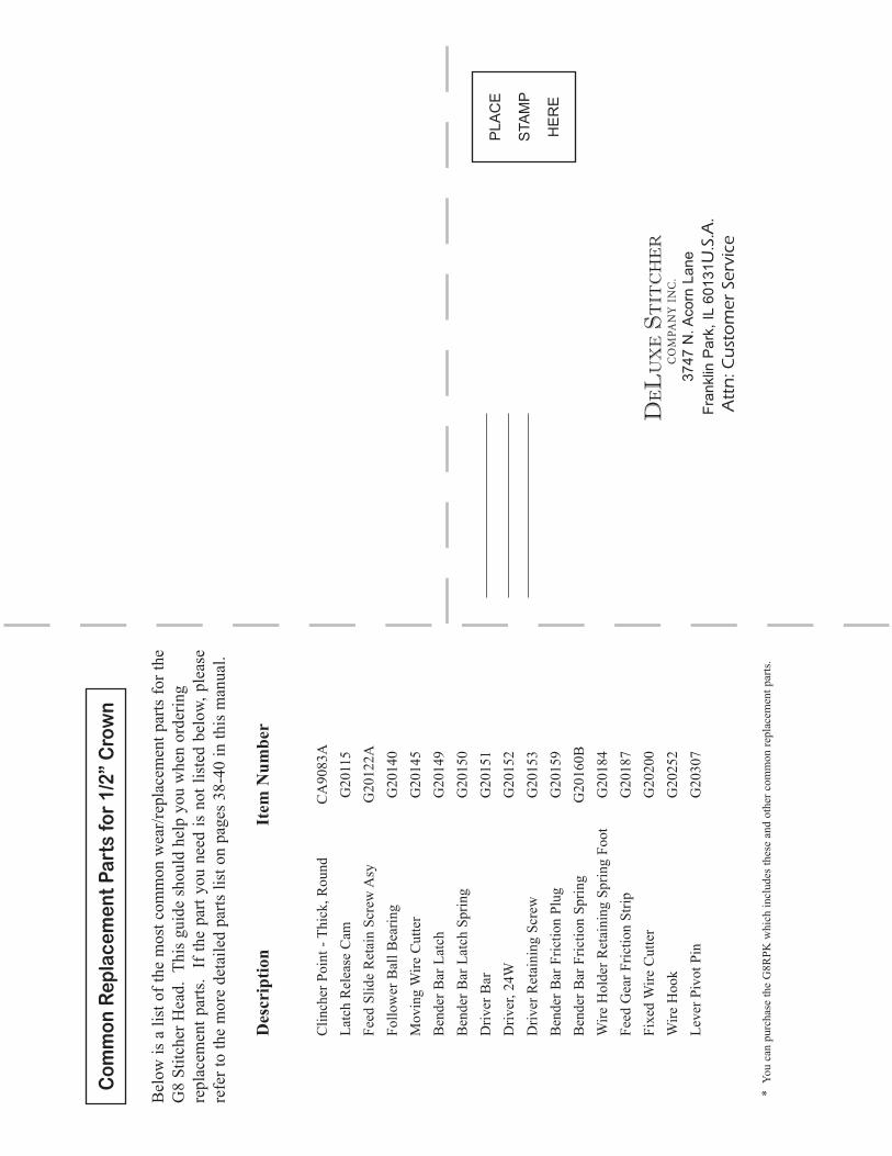
Com
mon
Rep
lace
men
t Par
ts fo
r 1/
2” C
row
n
Bel
ow is
a li
st o
f the
mos
t com
mon
wea
r/rep
lace
men
t par
ts fo
r the
G
8 St
itche
r Hea
d. T
his
guid
e sh
ould
hel
p yo
u w
hen
orde
ring
repl
acem
ent p
arts
. If
the
part
you
need
is n
ot li
sted
bel
ow, p
leas
e re
fer t
o th
e m
ore
deta
iled
parts
list
on
page
s 38
-40
in th
is m
anua
l.
D
escr
iptio
n
Item
Num
ber
C
linch
er P
oint
- Th
ick,
Rou
nd
CA
9083
A
Latc
h R
elea
se C
am
G20
115
Fe
ed S
lide
Ret
ain
Scre
w A
sy
G20
122A
Fo
llow
er B
all B
earin
g G
2014
0
Mov
ing
Wire
Cut
ter
G20
145
B
ende
r Bar
Lat
ch
G20
149
B
ende
r Bar
Lat
ch S
prin
g G
2015
0
Driv
er B
ar
G20
151
D
river
, 24W
G
2015
2
Driv
er R
etai
ning
Scr
ew
G20
153
B
ende
r Bar
Fric
tion
Plug
G
2015
9
Ben
der B
ar F
rictio
n Sp
ring
G20
160B
W
ire H
olde
r Ret
aini
ng S
prin
g Fo
ot
G20
184
Fe
ed G
ear F
rictio
n St
rip
G20
187
Fi
xed
Wire
Cut
ter
G20
200
W
ire H
ook
G20
252
Le
ver P
ivot
Pin
G
2030
7 *
YoucanpurchasetheG8R
PKwhichincludestheseandothercom
monreplacem
entparts.

59


DBSG8_0115
3747 Acorn Lane • Franklin Park • Illinois 60131Phone: 847-455-4400 • 800-634-0810
Fax: 847-455-4900 • 800-417-9251http://www.deluxestitcher.com
DELUXE STITCHERC O M P A N Y I N C .
®
ISP Stitching & Bindery Products