DELL/EMC CX SERIES INITIAL · PDF fileThird-party information provided to you courtesy of...
33
Third-party information provided to you courtesy of Dell. DELL/EMC CX SERIES INITIAL CONFIGURATION BEST PRACTICES PLANNING Abstract This white paper provides basic best practice recommendations for Dell/EMC CX Series ® storage system settings. The recommendations provide parameters that will apply to 80 percent of the configurations installed. February 2007
Transcript of DELL/EMC CX SERIES INITIAL · PDF fileThird-party information provided to you courtesy of...

Third-party information provided to you courtesy of Dell.
DELL/EMC CX SERIES INITIAL CONFIGURATION
BEST PRACTICES PLANNING
Abstract
This white paper provides basic best practice recommendations for Dell/EMC CX Series® storage systemsettings. The recommendations provide parameters that will apply to 80 percent of the configurationsinstalled.
February 2007
Copyright © 2005, 2007 EMC Corporation. All rights reserved.
EMC believes the information in this publication is accurate as of its publication date. Theinformation is subject to change without notice.
THE INFORMATION IN THIS PUBLICATION IS PROVIDED “AS IS.” EMC CORPORATIONMAKES NO REPRESENTATIONS OR WARRANTIES OF ANY KIND WITH RESPECT TO THEINFORMATION IN THIS PUBLICATION, AND SPECIFICALLY DISCLAIMS IMPLIEDWARRANTIES OF MERCHANTABILITY OR FITNESS FOR A PARTICULAR PURPOSE.
Use, copying, and distribution of any EMC software described in this publication requires anapplicable software license.
For the most up-to-date listing of EMC product names, see EMC Corporation Trademarks onEMC.com
All other trademarks used herein are the property of their respective owners.
Dell/EMC CX Series Initial ConfigurationBest Practices Planning 2
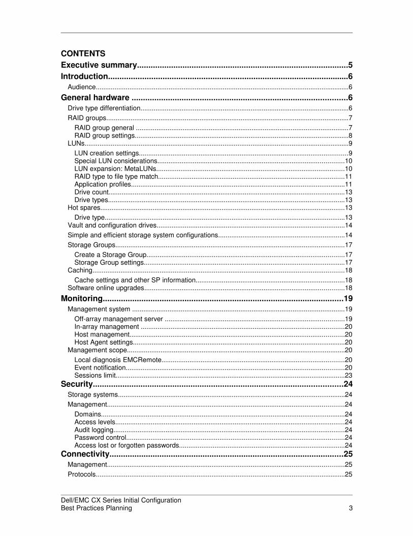
CONTENTS
Executive summary.............................................................................................5
Introduction..........................................................................................................6
Audience........................................................................................................................................6
General hardware ...............................................................................................6
Drive type differentiation................................................................................................................6
RAID groups..................................................................................................................................7
RAID group general ..................................................................................................................7RAID group settings...................................................................................................................8
LUNs..............................................................................................................................................9
LUN creation settings................................................................................................................9Special LUN considerations....................................................................................................10LUN expansion: MetaLUNs.....................................................................................................10RAID type to file type match....................................................................................................11Application profiles...................................................................................................................11Drive count...............................................................................................................................13Drive types...............................................................................................................................13
Hot spares...................................................................................................................................13
Drive type.................................................................................................................................13Vault and configuration drives.....................................................................................................14
Simple and efficient storage system configurations....................................................................14
Storage Groups...........................................................................................................................17
Create a Storage Group..........................................................................................................17Storage Group settings............................................................................................................17
Caching.......................................................................................................................................18
Cache settings and other SP information................................................................................18Software online upgrades...........................................................................................................18
Monitoring..........................................................................................................19
Management system ..................................................................................................................19
Off-array management server ................................................................................................19In-array management .............................................................................................................20Host management...................................................................................................................20Host Agent settings..................................................................................................................20
Management scope.....................................................................................................................20
Local diagnosis EMCRemote..................................................................................................20Event notification.....................................................................................................................20Sessions limit...........................................................................................................................23
Security..............................................................................................................24
Storage systems..........................................................................................................................24
Management...............................................................................................................................24
Domains...................................................................................................................................24Access levels...........................................................................................................................24Audit logging............................................................................................................................24Password control.....................................................................................................................24Access lost or forgotten passwords.........................................................................................24
Connectivity.......................................................................................................25
Management...............................................................................................................................25
Protocols......................................................................................................................................25
Dell/EMC CX Series Initial ConfigurationBest Practices Planning 3
iSCSI connections.......................................................................................................................25
NIC cards.................................................................................................................................25TOE cards................................................................................................................................25iSCSI security..........................................................................................................................25
Fibre Channel connections.........................................................................................................25
Emulex HBAs...........................................................................................................................26QLogic HBAs: QLogic settings................................................................................................26
Data path.....................................................................................................................................26
Host bus adapters....................................................................................................................26Dell/EMC CX Series SP ports.................................................................................................26Zoning......................................................................................................................................27Port-to-HBA relationships........................................................................................................27Fabric connectivity...................................................................................................................27Multipath software....................................................................................................................28LUN presentation.....................................................................................................................28RAID group to back-end bus connections...............................................................................28Back-end connectivity..............................................................................................................29
Clustering....................................................................................................................................29
Sun clusters.............................................................................................................................29VERITAS clusters....................................................................................................................29IBM clusters.............................................................................................................................29Windows clusters: Microsoft Cluster Server ...........................................................................30Linux (RedHat) clusters...........................................................................................................30HP TruCluster..........................................................................................................................30
Scaling: Storage system sizes.........................................................................30
Small storage system..............................................................................................................30Medium storage system...........................................................................................................30Large storage system..............................................................................................................30
Host connectivity.........................................................................................................................30
Exchange environments..............................................................................................................31
Disk-array enclosure (disk shelves) ...............................................................31
Availability....................................................................................................................................31
Drive types per DAE....................................................................................................................31
Drives per DAE............................................................................................................................31
Drive types per storage system...................................................................................................31
Drives per RAID group................................................................................................................32
Cabinets......................................................................................................................................32
Conclusion.........................................................................................................32
References.........................................................................................................32
Replication software....................................................................................................................32
Other references.........................................................................................................................32
Dell/EMC CX Series Initial ConfigurationBest Practices Planning 4
EXECUTIVE SUMMARY
This white paper is provided to expedite deployment of the Dell/EMC® CX3 Series. It defines howto best implement the new/enhanced technology into customer environments. The paper providesbest practices that will satisfy 80 percent of customer configurations; they meet the 80/20 rule.(The 80/20 rule states if X is done, X will satisfy 80 percent of the situations or configurations.)
The guidelines in this white paper are not rules but rather recommendations within the rules. Mostimplementations should be successful if these recommendations are followed. Using this paper,EMC can partner with customers to apply the customer’s own best practices policies (if any). Thisis a “living document,” changing with experience and the addition of new features.
This paper is broken down into five sections:
• General Hardware
• Monitoring
• Security
• Connectivity
• Scaling
There may be some overlap between sections as some capabilities may overlap.
The paper also notes cases where a configuration or feature may fall outside the 80 percent rule.Most often, these cases are based on performance or configuration limitations.
Best practice settings for performance are not included in this document. Although they are takeninto consideration here, they are not the primary focus. The primary focus of this paper is functionand ease of installation—not fine-tuning. To access the best practices for performance, refer toEMC Dell/EMC CX Series Best Practices for Fibre Channel Storage on EMC® Powerlink®.
Dell/EMC CX Series Initial ConfigurationBest Practices Planning 5

INTRODUCTION
Customers are requiring simpler installs on Dell/EMC CX Series CX3 Series storage systems.One way to accommodate this requirement, without reducing the power and flexibility of Dell/EMCCX Series storage systems, is to provide best practices that meet the 80/20 rule. Many customershave requested that EMC provide basic recommendations for configurations, and havesuggested that EMC “put a stake in the ground” for most configurations. This paper accomplishesthat for most configurations, from an operational and management perspective.
The primary environments this paper addresses are: file and print, basic database onlinetransaction processing (OLTP), and data warehouses. Video environments’ special modificationswill be noted as such when needed.
The settings included in this document are not rules but rather guidelines within rules. Forexample:
• Rule – RAID 5 supports up to 16 disks.
• Guideline – Set up RAID 5 in groups of five or nine disks.
If you want to see the rules, refer to the EMC Dell/EMC CX Series Open System ConfigurationGuide (either the documentation or the EMC Support Matrix).
Deviations from the best practice are allowed and encouraged, especially for experienced users.However, if you want a simple guide to maximize a successful installation, follow the bestpractice. The best practices are instructions, such as “set this up” or “use that setting.”References to best practices point to other documents that were written to address the specificneeds of a particular application or to maximize performance of the Dell/EMC CX Series.
Tables include recommended parameter settings for particular operations, such as creating aRAID group. The tables include the attribute name (as seen in Navisphere® User Interface), thebest practice setting, the default setting and any notes relating to the parameter.
Audience
This white paper is intended for EMC field personnel and customers who want to configure aDell/EMC CX Series for general use.
GENERAL HARDWARE
The Dell/EMC CX Series is a very flexible storage system that allows the administrator toconfigure it many different ways.
Drive type differentiation
For the purposes of configuration, the following characteristics can be used to differentiatebetween drives when identifying different configurations. Different models have different drivetypes, sizes, and rotational speeds.
• Technology - EMC supports two different drive types within the Dell/EMC CX Seriesstorage system: Fibre Channel (FC) and Advanced Technology Attachment (ATA).Both can be contained within one Dell/EMC CX Series but only one type can be inany one DAE.
• Size - EMC provides different sizes for drives based on type. EMC Fibre Channeldrive sizes are: 73 GB, 146 GB, 300 GB, and 500 GB. ATA/SATA-II drives areavailable in 500 GB capacity. Larger size drives of the same type are allowed asreplacement drives in the same RAID group. Remember that replacing a drive of onesize with one that is larger only provides you with the capacity of the smallest
Dell/EMC CX Series Initial ConfigurationBest Practices Planning 6
capacity drive in the RAID group. This usually coincides with the capacity of thereplaced drive.
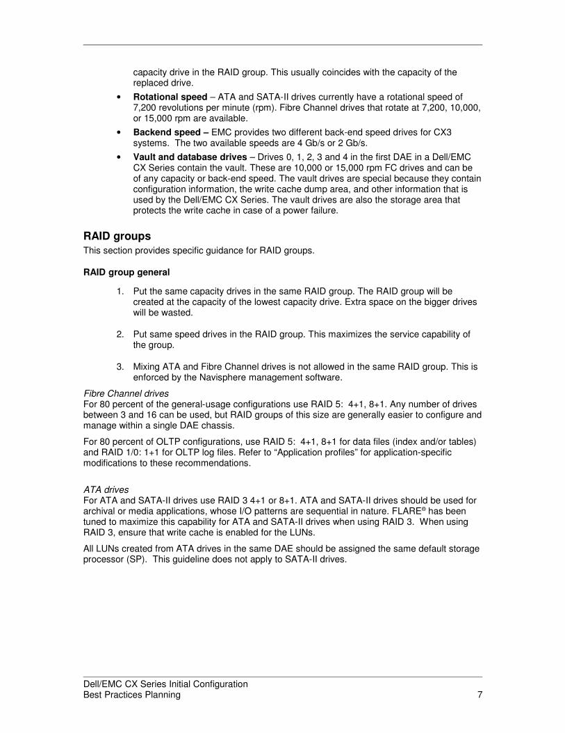
• Rotational speed – ATA and SATA-II drives currently have a rotational speed of7,200 revolutions per minute (rpm). Fibre Channel drives that rotate at 7,200, 10,000,or 15,000 rpm are available.
• Backend speed – EMC provides two different back-end speed drives for CX3systems. The two available speeds are 4 Gb/s or 2 Gb/s.
• Vault and database drives – Drives 0, 1, 2, 3 and 4 in the first DAE in a Dell/EMCCX Series contain the vault. These are 10,000 or 15,000 rpm FC drives and can beof any capacity or back-end speed. The vault drives are special because they containconfiguration information, the write cache dump area, and other information that isused by the Dell/EMC CX Series. The vault drives are also the storage area thatprotects the write cache in case of a power failure.
RAID groups
This section provides specific guidance for RAID groups.
RAID group general
1. Put the same capacity drives in the same RAID group. The RAID group will becreated at the capacity of the lowest capacity drive. Extra space on the bigger driveswill be wasted.
2. Put same speed drives in the RAID group. This maximizes the service capability ofthe group.
3. Mixing ATA and Fibre Channel drives is not allowed in the same RAID group. This isenforced by the Navisphere management software.
Fibre Channel drivesFor 80 percent of the general-usage configurations use RAID 5: 4+1, 8+1. Any number of drivesbetween 3 and 16 can be used, but RAID groups of this size are generally easier to configure andmanage within a single DAE chassis.
For 80 percent of OLTP configurations, use RAID 5: 4+1, 8+1 for data files (index and/or tables)and RAID 1/0: 1+1 for OLTP log files. Refer to “Application profiles” for application-specificmodifications to these recommendations.
ATA drivesFor ATA and SATA-II drives use RAID 3 4+1 or 8+1. ATA and SATA-II drives should be used forarchival or media applications, whose I/O patterns are sequential in nature. FLARE® has beentuned to maximize this capability for ATA and SATA-II drives when using RAID 3. When usingRAID 3, ensure that write cache is enabled for the LUNs.
All LUNs created from ATA drives in the same DAE should be assigned the same default storageprocessor (SP). This guideline does not apply to SATA-II drives.
Dell/EMC CX Series Initial ConfigurationBest Practices Planning 7
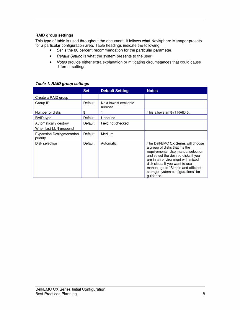
RAID group settings
This type of table is used throughout the document. It follows what Navisphere Manager presetsfor a particular configuration area. Table headings indicate the following:
• Set is the 80 percent recommendation for the particular parameter.
• Default Setting is what the system presents to the user.
• Notes provide either extra explanation or mitigating circumstances that could causedifferent settings.
Table 1. RAID group settings
Set Default Setting Notes
Create a RAID group
Group ID Default Next lowest availablenumber
Number of disks 9 1 This allows an 8+1 RAID 5.
RAID type Default Unbound
Automatically destroy
When last LUN unbound
Default Field not checked
Expansion Defragmentationpriority
Default Medium
Disk selection Default Automatic The Dell/EMC CX Series will choosea group of disks that fits therequirements. Use manual selectionand select the desired disks if youare in an environment with mixeddisk sizes. If you want to usemanual, go to “Simple and efficientstorage system configurations“ forguidance.
Dell/EMC CX Series Initial ConfigurationBest Practices Planning 8

LUNs
LUNs are created from a RAID group. The RAID type for a RAID group will be assigned when thefirst LUN is bound on the RAID group. LUNs can be bound in many different ways on a Dell/EMCCX Series. For maximum availability all LUNs should be bound with protected RAID, such asRAID 1/0, or RAID 5. A number of hot spares should also be bound (see hot spares section).
LUN creation settings
Table 2 lists the recommended settings for creating LUNs.
Table 2. LUN creation settings
Set Default setting Notes
Bind a LUN
RAID type RAID 5,RAID 3,RAID 1 orRAID 1/0
RAID 5 Refer to the “Application section.
RAID 5 is considered the bestcost/performance balance for protectedRAID.
RAID Group ID Choose any 1 Choose the RAID Group ID you wish toput this LUN into. If none exists, clickon new.
LUN ID See note Next lowestavailable
Try to use an even and odd numberingsystem to reflect the default owner: Forexample, use even for SPA and odd forSP B.
No Initial Verify Default No (box is blank) Do not send data to the LUN until thebackground verify operation iscomplete.
Rebuild priority Default ASAP
Verify priority Default ASAP
Default owner Auto Either SP A or SPB depending on theLUN allocation toeach
Alignment offset See note 0 The alignment offset is operatingsystem (OS) dependent. Windows: 63 For other OSs or use with replicationsoftware, use the default and see thesection directly below this table forspecific recommendations.
Read and write cache Default Enabled
Enable auto assign Default No (box blank)
LUN size See note 1 GB LUN size must be compatible with theoperating system.
Number of LUNs to bind See note 1 When adding LUNs to an existingsystem. select 1.
For Windows systems:
If you plan to use replication software (SnapView, SAN Copy™ or MirrorView™) with a LUN, usethe default offset and align using diskpar. The white paper EMC Dell/EMC CX Series Best
Practices for Fibre Channel Storage has more details.
Dell/EMC CX Series Initial ConfigurationBest Practices Planning 9
Special LUN considerations
When binding LUNs destined for the reserved LUN pool, give these LUNs high numbers. Placethese LUNs in the “private LUN number” range. If the array to be configured supports a max of2,048 addressable LUNs, then these reserved LUNs should start at 2100 and increase as morereserved LUNs are added.
LUN expansion: MetaLUNs
Create metaLUNs from LUNs in separate RAID 5 RAID groups. Use the striping method and waitfor the extra space. This will provide the best performance in the majority of environments.
Striping metaLUNs typically provides high performance but requires the stripe to be built beforethe extra space becomes available. Concatenation provides immediate space availability but willnot balance the I/Os across all the drives. The extra space must be used to get the added diskbenefit from the concatenation.
The two can be combined in a concatenated stripe. This provides both immediate spaceavailability and the potential performance benefit of striping.
For the stripe multiplier use:
• For four-disk LUNs use 4 – a four-disk LUN is a 4+1 RAID 3 or RAID 5 or a 4+4RAID 1/0.
• For eight-disk LUNs use 2 – an eight-disk LUN is an 8+1 RAID 3 or RAID 5.
• If RAID 1, set to 2.
• A good general purpose number is 4.
LUNs should be expanded onto "like" RAID groups (that is, expand a 4+1 R5 LUN into other 4+1R5 RAID groups to retain similar geometry).
For user capacity, use the current capacity for planned metaLUN creation. Use the maximumcapacity setting for unplanned metaLUN creation. While metaLUN expansion is supported on allDell/EMC CX Series arrays, each operating system has separate restrictions regarding thesupport of online capacity expansion. Refer to your operating system vendor for details.
All member LUNs of a metaLUN should be assigned to the same default SP.
Dell/EMC CX Series Initial ConfigurationBest Practices Planning 10
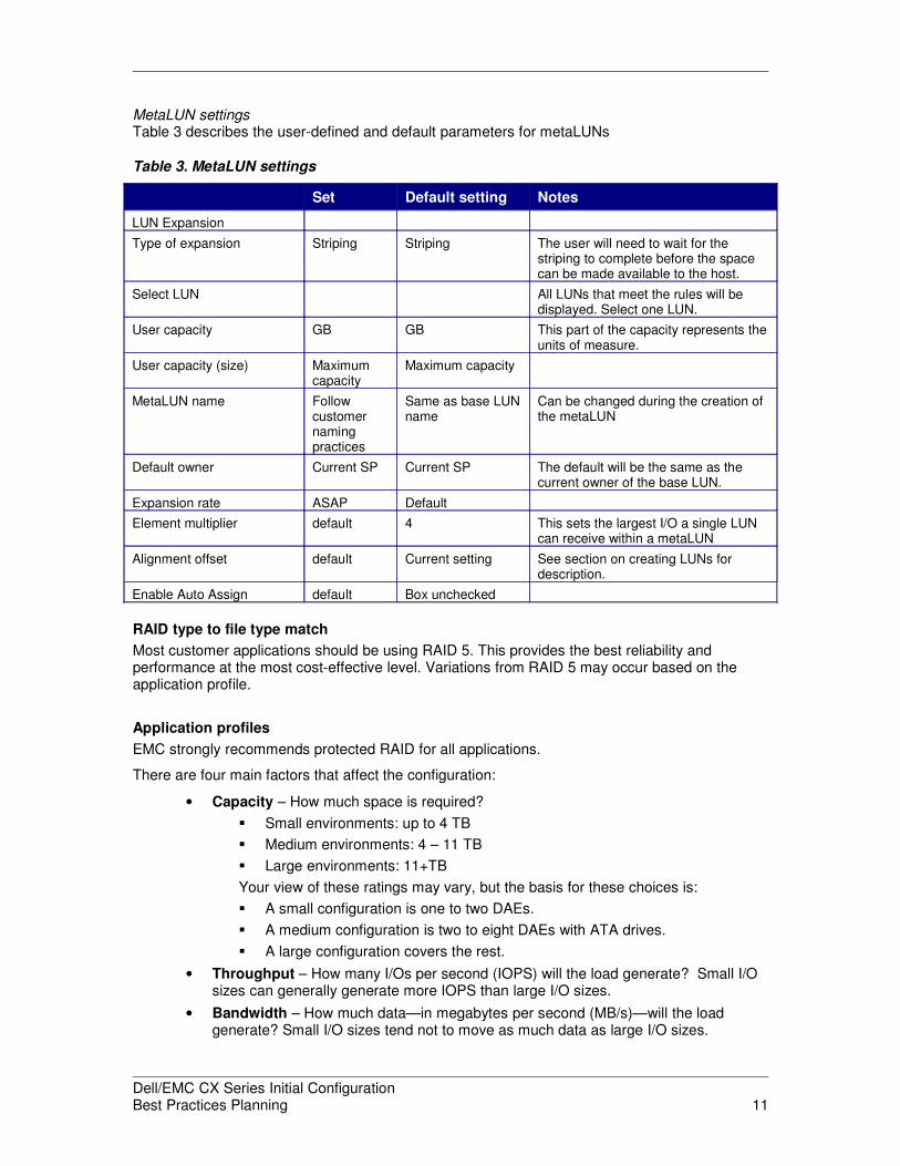
MetaLUN settingsTable 3 describes the user-defined and default parameters for metaLUNs
Table 3. MetaLUN settings
Set Default setting Notes
LUN Expansion
Type of expansion Striping Striping The user will need to wait for thestriping to complete before the spacecan be made available to the host.
Select LUN All LUNs that meet the rules will bedisplayed. Select one LUN.
User capacity GB GB This part of the capacity represents theunits of measure.
User capacity (size) Maximumcapacity
Maximum capacity
MetaLUN name Followcustomernamingpractices
Same as base LUNname
Can be changed during the creation ofthe metaLUN
Default owner Current SP Current SP The default will be the same as thecurrent owner of the base LUN.
Expansion rate ASAP Default
Element multiplier default 4 This sets the largest I/O a single LUNcan receive within a metaLUN
Alignment offset default Current setting See section on creating LUNs fordescription.
Enable Auto Assign default Box unchecked
RAID type to file type match
Most customer applications should be using RAID 5. This provides the best reliability andperformance at the most cost-effective level. Variations from RAID 5 may occur based on theapplication profile.
Application profiles
EMC strongly recommends protected RAID for all applications.
There are four main factors that affect the configuration:
• Capacity – How much space is required?
� Small environments: up to 4 TB
� Medium environments: 4 – 11 TB
� Large environments: 11+TB
Your view of these ratings may vary, but the basis for these choices is:
� A small configuration is one to two DAEs.
� A medium configuration is two to eight DAEs with ATA drives.
� A large configuration covers the rest.
• Throughput – How many I/Os per second (IOPS) will the load generate? Small I/Osizes can generally generate more IOPS than large I/O sizes.
• Bandwidth – How much data—in megabytes per second (MB/s)—will the loadgenerate? Small I/O sizes tend not to move as much data as large I/O sizes.
Dell/EMC CX Series Initial ConfigurationBest Practices Planning 11

• Response Time – This is the time it takes to complete a transaction. A transactioncan be one or many I/Os. Typical response time is calculated on a per-I/O basis.Online transaction processing (OLTP) environments typically measure response timeby a full transaction, which is usually many I/Os.
Online transaction processing (OLTP)OLTP environments have special behaviors and requirements. Typically, a database will havetwo primary components: the table space and the log. No transaction completes without a logentry. Logs use a tiny fraction of the table space. Logs are response-time sensitive and small insize, so the best practice for a log is a RAID 1/0 with 73 GB 15k rpm drives. Best practice fortable spaces is FC 73 GB 15k rpm 4+1 RAID 5.
Ideally a transactional database should spread its data across as many drives a possible. In anOLTP environment the number of drives will have a great effect on response time for any givenload. EMC testing uses large drive counts for ideal OLTP environments. Those counts include120, 240, and 480 drives. The relationship of drive counts to response time is roughly linear. Soconfigurations in our testing have shown that for a given load, half the drives double the responsetime.
Please check with the database vendor for specific caveats regarding response time and I/O load.
Low to midsize database activityDatabases with user counts up to 160 are considered low to midsize OLTP environments.Generally, the load is a 66 percent to 33 percent mix of reads to writes, with a log write pertransaction. Typical I/O counts for a single user would be approximately 30. Logs are response-time sensitive and small in size, so the best practice for a log is a RAID 1 with 73 GB 15k rpmdrives. Best practice for table spaces is FC 73 GB 15k rpm 4+1 RAID 5. Please be aware of theresponse time requirements and size constraints.
Medium database activityDatabases with user counts of 161 to 350 are considered mid-to-large OLTP environments.Generally, the load is a 66 percent to 33 percent mix of reads to writes with a log write pertransaction. The typical approximate I/O count for a single user is 30. Logs are response-timesensitive and small in size, so the best practice for a log is a RAID 1 with 73 GB 15k rpm drives.Best practice for table spaces is FC 73 GB 15k rpm 4+1 RAID 5.
High database activityDatabases with user counts of 351+ are considered large OLTP environments. Generally, theload is a 66 percent to 33 percent mix of reads to writes, with a log write per transaction. Thetypical approximate I/O count for a single user is 30. Logs are response-time sensitive and smallin size, so the best practice for a log is a RAID 1/0 with 73 GB 15k rpm drives. Best practice fortable spaces for most database environments is FC 73 GB 15k rpm 4+4 RAID 1/0.
OracleConsult the Implementing Oracle on EMC Dell/EMC CX Series Storage Systems paper forOracle-specific recommendations.
DB2Consult Practitioner's Guide - EMC Database Services DB2 UDB on EMC Powerlink for DB2-specific best practices.
SQL ServerConsult EMC Dell/EMC CX Series Database Storage Solutions Microsoft SQL Server 2000 BestPractices on EMC Powerlink for SQL Server advice.
ExchangeExchange environments are somewhat OLTP-like, where response time is crucial but differentbecause the I/O pattern is variable in both load and I/O size. Use the exchange best practices
Dell/EMC CX Series Initial ConfigurationBest Practices Planning 12

paper published by Microsoft for the correct configuration. You can also use EMC Dell/EMC CXSeries Storage Solutions Microsoft Exchange 2003 Best Practices on EMC Powerlink.
Backup-to-diskBackup-to-disk is sequential in nature and typically uses medium (64 KB) to large (256 KB) I/Osizes. For these types of applications use ATA or SATA-II drives, although you can use FibreChannel drives. To calculate the number of Fibre Channel drives use the “rule-of-thumb” valuesin EMC Dell/EMC CX Series Best Practices for Fibre Channel Storage.
For ATA or SATA-II drives use RAID 3 4+1 or 8+1.
WEB intelligence report repositories WEB intelligence report repositories are typically data-warehouse-like environments. They collectdata for later analysis. The data collection may be either transactional or periodic collectionsessions. The analysis is likely to be scans and builds. The I/O profile for these environments ishighly sequential reads and writes. During queries, the writes go to a temp area. During datacollection, writes go to the main repository.
Use 8+1 RAID 5 LUNs. Fibre Channel drives should be used for high performance, especially ifthe data-collection method is transactional. If the data-collection method is sequential, then ATAor SATA-II drives should suffice.
Drive count
For RAID 5 the best all-around configuration is five or nine disks. RAID 5 groups can beconfigured with three to 16 disks.
For RAID 1/0 EMC recommends four to ten disks. RAID 1/0 groups must be grown by adding twodisks at a time.
Drive types
For Fibre Channel use 10k rpm drives for back-end loops running at 2 Gb/s or 15k rpm drives forback-end loops running at 4 Gb/s.
Fibre Channel applications include: OLTP, file and print, data warehousing and video.
ATA or SATA-II applications include: backup-to-disk, data warehousing and online archive.
Hot spares
A hot spare is an extra drive for each drive type. EMC strongly recommends a minimum of onehot spare for each type (ATA, SATA-II or FC) of disk in the storage system and one more forevery 30 drives of the same type. For hot spares to be effective they must be as large as thelargest drive of that type in the storage system. Remember, however, if you have high-speeddrives in your configuration, you may also want hot spares that match the speed of the fastestdrive. For example, if the system has 146 GB and 300 GB FC drives in the system, the hotspares must be 300 GB to be able to service the 300 GB drives.
Consult the Dell/EMC CX Series Global Hot Spares – Characteristics and Usage Strategies whitepaper for additional details on hot spares.
Drive type
Dell/EMC CX Series supports two different drive types. Within drive types there are differentcapacities and rotational speeds. This section addresses how these apply to hot spares.
Dell/EMC CX Series Initial ConfigurationBest Practices Planning 13
Drive sizeEMC has currently certified different FC and ATA/SATA-II drive capacities. EMC does not requireany specific disk size within the supported list of disk sizes and types. Select disk sizes and typesbased on capacity and performance requirements.
Drive technologyThe chosen technology must match the performance requirements of the customer application.For OLTP environments, data warehouses, and environments where response time1 is critical,use FC drives. For backup-to-disk, longer term storage, and applications where response time isnot critical, use ATA/SATA-II drives.
Vault and configuration drives
The first five drives in a system are used as database and vault drives. These disks are used foronline upgrade operations, replication software management, and Navisphere configurationmanagement and tracking. The RAID group containing the first five drives of the system shouldnot be used for file types other than file-sharing LUNs and should be considered to already havea busy LUN.
Navisphere uses the first three drives for caching online upgrade data. Heavy host I/O during anonline upgrade can cause the upgrade to time out, so it is recommended that before an onlineupgrade commences, the host load be reduced to 100 IOPS per drive. Backups should not bescheduled nor should backups be placed on hold during an online upgrade operation.
Simple and efficient storage system configurations
The minimum CX3-80 configuration consists of one SPS assembly, one SPE with two SPs, andone DAE with five drives.
For DAEs with hot spares, configure 1x 8+1 and 1x 4+1 and one hot spare. For DAEs without hotspares, create 3x 4+1 RAID groups.
1 Response time is defined as the difference in time from when the user begins the computer request until
the user gets the data requested or a write completion notification. Response time is how a human
measures performance.
Dell/EMC CX Series Initial ConfigurationBest Practices Planning 14
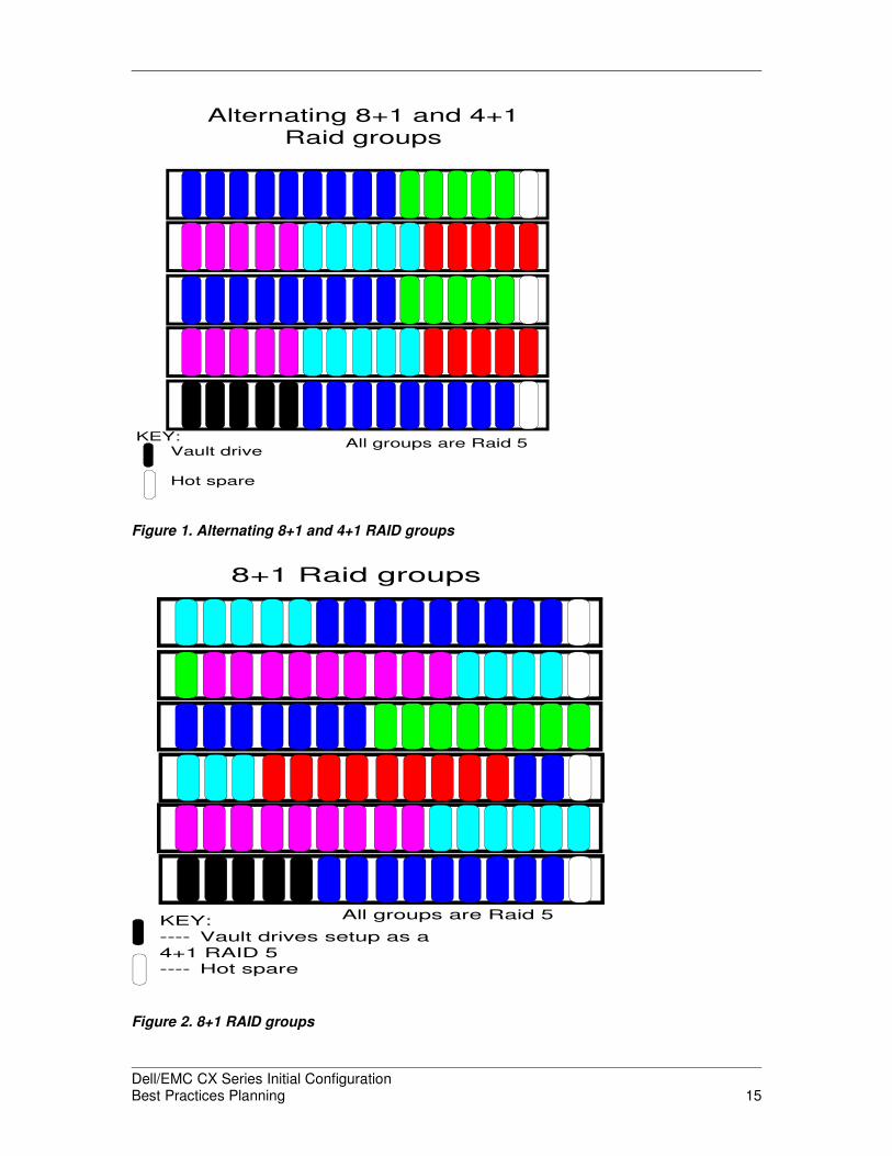
KEY:Vault drive
Hot spare
Alternating 8+1 and 4+1Raid groups
All groups are Raid 5
Figure 1. Alternating 8+1 and 4+1 RAID groups
KEY:---- Vault drives setup as a
4+1 RAID 5---- Hot spare
All groups are Raid 5
8+1 Raid groups
Figure 2. 8+1 RAID groups
Dell/EMC CX Series Initial ConfigurationBest Practices Planning 15
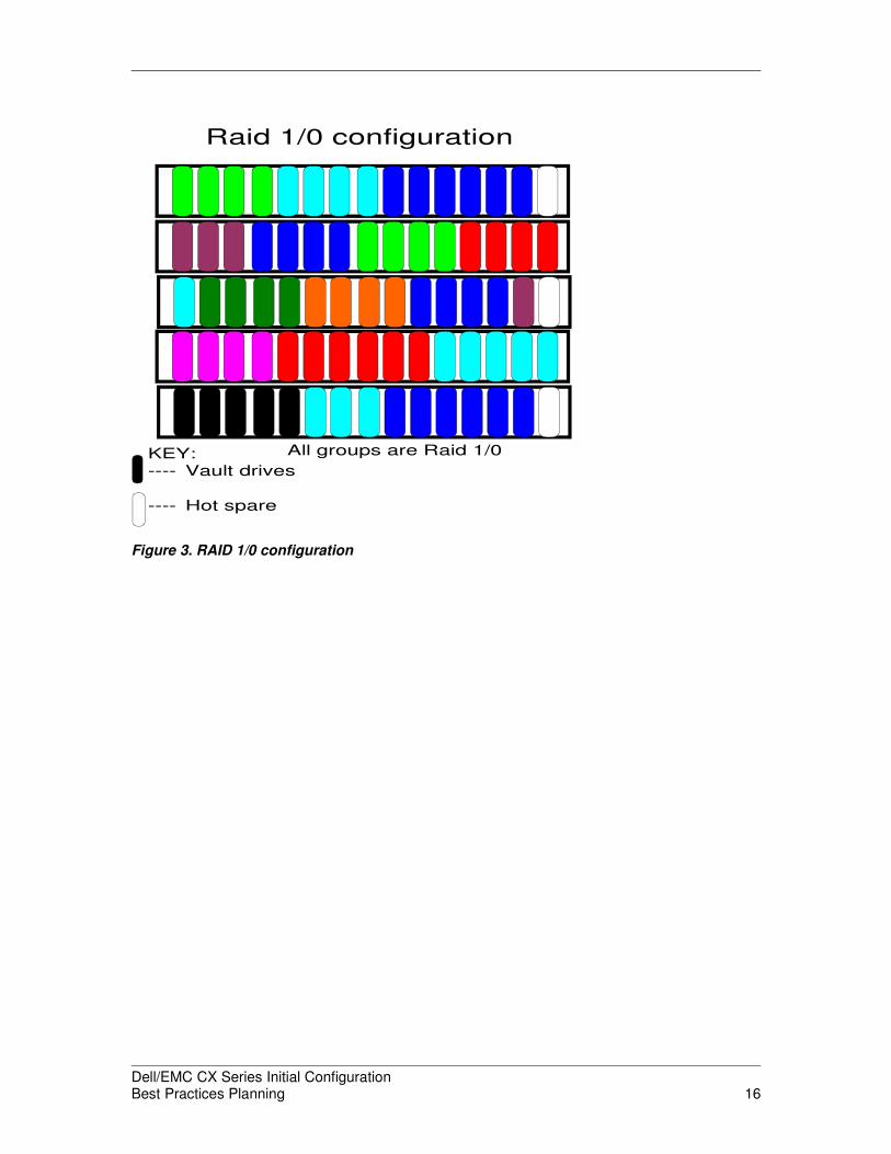
KEY:---- Vault drives
---- Hot spare
All groups are Raid 1/0
Raid 1/0 configuration
Figure 3. RAID 1/0 configuration
Dell/EMC CX Series Initial ConfigurationBest Practices Planning 16
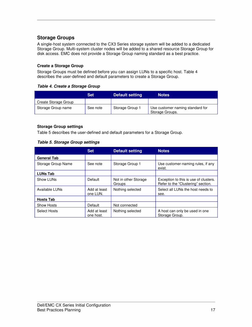
Storage Groups
A single-host system connected to the CX3 Series storage system will be added to a dedicatedStorage Group. Multi-system cluster nodes will be added to a shared resource Storage Group fordisk access. EMC does not provide a Storage Group naming standard as a best practice.
Create a Storage Group
Storage Groups must be defined before you can assign LUNs to a specific host. Table 4describes the user-defined and default parameters to create a Storage Group.
Table 4. Create a Storage Group
Set Default setting Notes
Create Storage Group
Storage Group name See note Storage Group 1 Use customer naming standard forStorage Groups.
Storage Group settings
Table 5 describes the user-defined and default parameters for a Storage Group.
Table 5. Storage Group settings
Set Default setting Notes
General Tab
Storage Group Name See note Storage Group 1 Use customer-naming rules, if anyexist.
LUNs Tab
Show LUNs Default Not in other StorageGroups
Exception to this is use of clusters.Refer to the “Clustering” section.
Available LUNs Add at leastone LUN.
Nothing selected Select all LUNs the host needs tosee.
Hosts Tab
Show Hosts Default Not connected
Select Hosts Add at leastone host.
Nothing selected A host can only be used in oneStorage Group.
Dell/EMC CX Series Initial ConfigurationBest Practices Planning 17

Caching
For 80 percent of the configurations, enable both read and write cache. Assign as much aspossible to write cache. Split the remaining memory between SP A read cache and SP B readcache. Ensure that read and write cache is enabled for each LUN.
Cache settings and other SP information
Table 6 describes the user-defined and default storage system properties.
Table 6. Cache settings and SP information
Properties Set Default setting Notes
General Tab
Name See note CXtype_ipSPA_ipSPB Use Customer Naming rules
Statistics Logging Box checked Box not checked
Cache Tab
Page Size Default 8 KB
Low Watermark Default 60
High Watermark Default 80
Enable Watermarks Default Box checked
SP A Read Cache Box checked Box not checked
SP B Read Cache Box checked Box not checked
Write Cache Box checked Box not checked
HA Cache Vault Default Box checked
Memory Tab
SP A/SP B Read Cache See Note 0 Leftover memory from write cacheshould be split between SP A and SP B read cache.
Write Cache As much asallowed
0 Depends on Dell/EMC CX Seriesmodel
RAID 3 Memory Do not use 0Storage Access Tab
Access Control Enabled Box checked Box not checkedSoftware Tab
Commit See note This button pertains to upgrades.This button is grayed out if commithas already been done.
Revert See note This button pertains to upgrades.This is grayed out if commitalready done.
Software online upgrades
EMC recommends Host Agents be upgraded as soon as possible so they are the same revisionas the Navisphere revision on the storage system. The management station must be running thesame revision as the highest revision of Navisphere running in the domain. Navisphere softwareis backwards-compatible, so the management station may be upgraded before the storagesystems are upgraded.
Upgrades to the storage system can be achieved by an operation called online upgrade. Onlineupgrades require that no more than 100 I/Os are running on the first five disks in the storagesystem. EMC recommends that all online upgrades be performed at off-peak hours.
Dell/EMC CX Series Initial ConfigurationBest Practices Planning 18
The Dell/EMC CX Series allows reverting to a prior revision as long as the FLARE code has notbeen committed. The tradeoffs are:
• No changes are allowed to the Dell/EMC CX Series.
• New features in the new revision of FLARE may not be usable.
Not committing allows you to confirm that the basic I/O functions work in your environment. Oncecommitted, the FLARE code can only be upgraded. EMC recommends committing the newFLARE revision at installation. Therefore, the ability to revert should be considered the exception.
Ensure all host, layered application and switch components (driver, agent, and firmware) areupgraded to maintain compatibility.
MONITORING
This section discusses the different management methods available to the user.
Management system
To manage the storage system, use the installed management software.
Access to the management system requires browser software. EMC recommends InternetExplorer, Netscape, and/or Mozilla, depending upon the OS.
Use Java JRE revision 1.4.2 for the browser. Note that this may change faster than this documentis revised. Navisphere will tell you if you are running the wrong revision of Java and point you tothe web site for the correct version. If you are not running the correct revision of Java, theNavisphere UI will send the user to the Java site. It is therefore also recommended that thesystem running the browser have access to a public network.
A Dell/EMC CX Series agent is not required on the system using a browser connection tomanage a Dell/EMC CX Series domain unless the system has a FC or iSCSI connection to theDell/EMC CX Series and is used to manage a legacy Dell/EMC CX Series via portals.
Off-array management server
EMC supports management of a Dell/EMC CX Series from either a management station or thestorage system itself. The following are the EMC recommendations for off-array management.
• To manage a Dell/EMC CX Series using the off-array management server, thatstation must be a member of a Dell/EMC CX Series domain.
• For management stations running pre-release 19 software, EMC recommends asingle management server manage no more than 30 storage systems at one time.The storage systems can be managed as one session if they are all placed in adomain.
• For management stations running post-release 19 software, EMC recommends nomore than 72 total storage systems in the multi-domain configuration. The storagesystems may be in one domain or several domains.
• The server should be a Windows server running at least Windows 2000 SP4. Theserver should have at least a 1-GHz CPU and 512 MB of RAM.
• The server used for off-array management should not be running any productionapplication. You can use the same server as the CLARalert® workstation. Dell/EMCCX Series should be in the same domain as the management station of Dell/EMC CXSeries.
Dell/EMC CX Series Initial ConfigurationBest Practices Planning 19
In-array management
EMC supports management of the Dell/EMC CX Series directly. The storage system limitsrecommended for off-array management also apply to in-array management. EMC does not havea best practice for which management method to use; both off-array and in-array are effectiveways to manage a Dell/EMC CX Series. Follow your corporate standards for Navisphere useraccount names. This will cut down on confusion and allow for better accounting and securitymeasures.
Host management
The Navisphere Management Suite provides several options for host management based on thelevel of service desired, the mode in which the host component will run, and the level of requiredhost-storage system communication. EMC recommends the use of the Navisphere Host Agent asthis is the most full-featured option.
The Host Agent automates the establishment of connectivity with the storage system byidentifying the host. The agent also provides mount information to the LUNs. This information isused by the storage manager to map storage system LUNs to the host file systems. EMCrecommends that the Host Agent software and the Navisphere software running in the Dell/EMCCX Series be at the same revision.
The Host Agent runs as a daemon/service on the host system. If a persistent service is notdesired, EMC recommends the Server Registration Utility for host management. This utility is runon demand and performs host registration and LUN/volume mapping functions.
Host Agent settings
Set the default privilege settings as shown below:
system@SPA_IPaddresssystem@SPB_IPaddresssystem@CallHomePC_IPaddressWindowsUser@CallHomePC_IPaddress
Set host agents polling to 120.
Management scope
The scope provides access to either local or full domain access.
• Global – User account can access all subsystems in the domains.
• Local – User can only access the particular subsystem.
Use Global scope for work in any domain.
Local diagnosis EMCRemote
EMCRemote is a remote access utility used by EMC support for dial-in diagnostics andtroubleshooting. Originally developed for the Symmetrix® line, it is now embedded into theDell/EMC CX Series CLARalert package.
Event notification
By default, notification is not enabled. Have EMC install CLARalert software on the managementworkstation. The Phone Home software provides a template of events that EMC considers PhoneHome worthy events. Do not add to this list.
Dell/EMC CX Series Initial ConfigurationBest Practices Planning 20

Event MonitorThe default template provides logging capability only. Critical and hard errors will be logged. Donot change this template.
Event Monitor settings
In the Monitors tab of the Navisphere UI, right-click Templates and select Create NewTemplate. ClarAlert will use Event Monitor, so at the minimum use these settings. If you wish toextend alerting internally to your company, use the other options shown in Table 7.
Table 7. Event Monitor settings
Set Default setting Notes
General Tab
Events ExplicitEvents
General Events selected by EMC
Log to System Logs Default Box unchecked
Combine Events forStorage System.
BoxChecked
Box unchecked
E-mail Tab As needed in special cases,consult documentation.
Email To Default Field empty
Cc Default Field empty
From Default Field empty
Subject Default Field empty
SNMP Server Default Field empty
Use Default Message Default Box checked
Paging Tab As needed in special cases,consult documentation.
Use Modem Default Box checked
All Other Fields Default Field empty
SNMP Tab As needed in special cases,consult documentation.
All Fields Default Field empty
Phone HomePhone Home software is provided by EMC and installed on a Windows server during theDell/EMC installation at a new site. The newly installed Dell/EMC must be setup to talk to thePhone Home system during installation. The Phone Home function means the environmentnotifies EMC of significant events on the Dell/EMC. These events are preset during Phone Homeinstallation but the customer may add more events if they desire.
Best practice: Do not change the event list.
Dell/EMC CX Series Initial ConfigurationBest Practices Planning 21
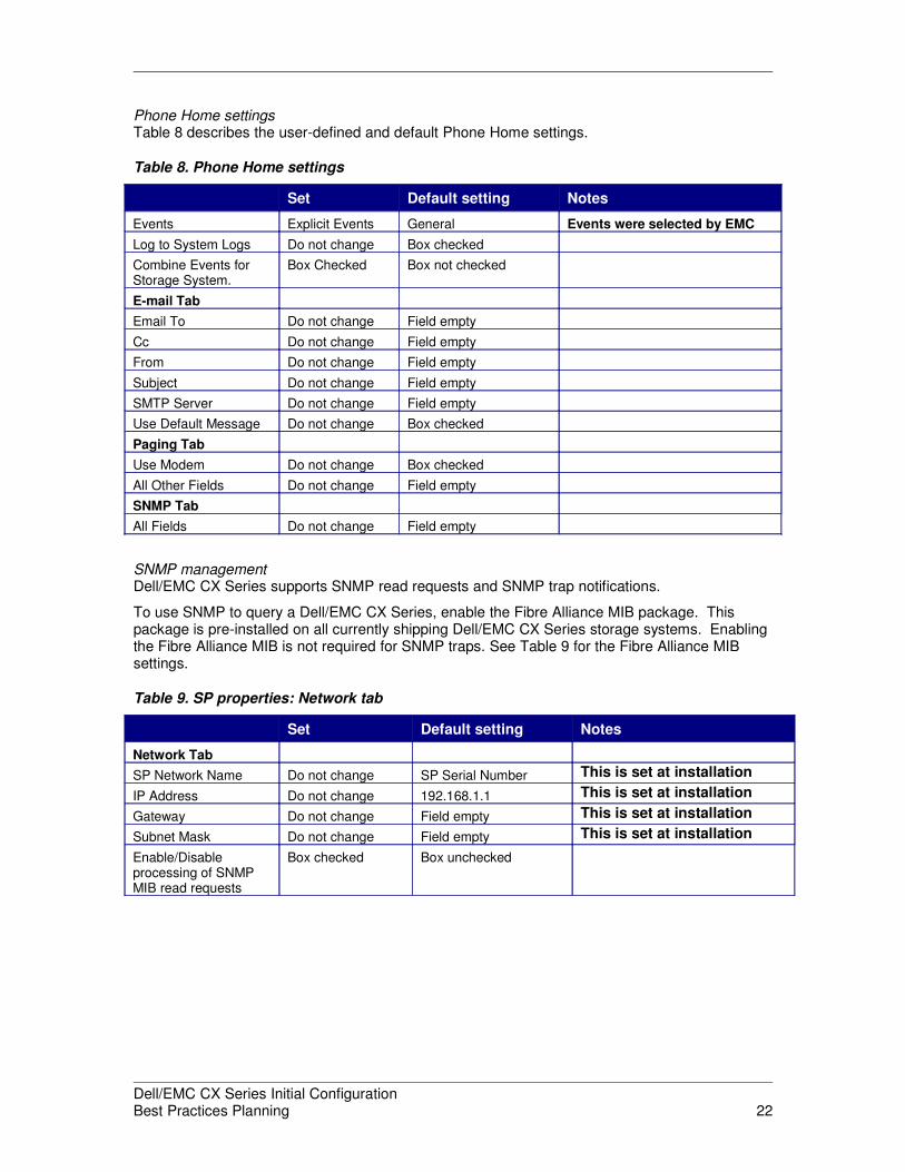
Phone Home settingsTable 8 describes the user-defined and default Phone Home settings.
Table 8. Phone Home settings
Set Default setting Notes
Events Explicit Events General Events were selected by EMC
Log to System Logs Do not change Box checked
Combine Events forStorage System.
Box Checked Box not checked
E-mail Tab
Email To Do not change Field empty
Cc Do not change Field empty
From Do not change Field empty
Subject Do not change Field empty
SMTP Server Do not change Field empty
Use Default Message Do not change Box checked
Paging Tab
Use Modem Do not change Box checked
All Other Fields Do not change Field empty
SNMP Tab
All Fields Do not change Field empty
SNMP managementDell/EMC CX Series supports SNMP read requests and SNMP trap notifications.
To use SNMP to query a Dell/EMC CX Series, enable the Fibre Alliance MIB package. Thispackage is pre-installed on all currently shipping Dell/EMC CX Series storage systems. Enablingthe Fibre Alliance MIB is not required for SNMP traps. See Table 9 for the Fibre Alliance MIBsettings.
Table 9. SP properties: Network tab
Set Default setting Notes
Network Tab
SP Network Name Do not change SP Serial Number This is set at installation
IP Address Do not change 192.168.1.1 This is set at installation
Gateway Do not change Field empty This is set at installation
Subnet Mask Do not change Field empty This is set at installation
Enable/Disableprocessing of SNMPMIB read requests
Box checked Box unchecked
Dell/EMC CX Series Initial ConfigurationBest Practices Planning 22
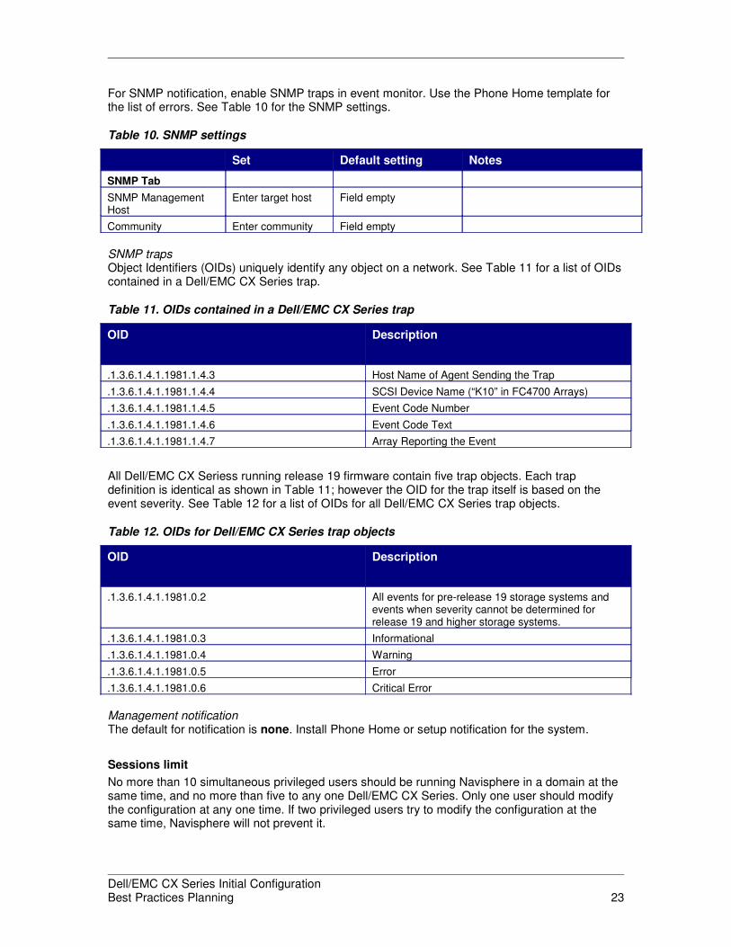
For SNMP notification, enable SNMP traps in event monitor. Use the Phone Home template forthe list of errors. See Table 10 for the SNMP settings.
Table 10. SNMP settings
Set Default setting Notes
SNMP Tab
SNMP ManagementHost
Enter target host Field empty
Community Enter community Field empty
SNMP trapsObject Identifiers (OIDs) uniquely identify any object on a network. See Table 11 for a list of OIDscontained in a Dell/EMC CX Series trap.
Table 11. OIDs contained in a Dell/EMC CX Series trap
OID Description
.1.3.6.1.4.1.1981.1.4.3 Host Name of Agent Sending the Trap
.1.3.6.1.4.1.1981.1.4.4 SCSI Device Name (“K10” in FC4700 Arrays)
.1.3.6.1.4.1.1981.1.4.5 Event Code Number
.1.3.6.1.4.1.1981.1.4.6 Event Code Text
.1.3.6.1.4.1.1981.1.4.7 Array Reporting the Event
All Dell/EMC CX Seriess running release 19 firmware contain five trap objects. Each trapdefinition is identical as shown in Table 11; however the OID for the trap itself is based on theevent severity. See Table 12 for a list of OIDs for all Dell/EMC CX Series trap objects.
Table 12. OIDs for Dell/EMC CX Series trap objects
OID Description
.1.3.6.1.4.1.1981.0.2 All events for pre-release 19 storage systems andevents when severity cannot be determined forrelease 19 and higher storage systems.
.1.3.6.1.4.1.1981.0.3 Informational
.1.3.6.1.4.1.1981.0.4 Warning
.1.3.6.1.4.1.1981.0.5 Error
.1.3.6.1.4.1.1981.0.6 Critical Error
Management notificationThe default for notification is none. Install Phone Home or setup notification for the system.
Sessions limit
No more than 10 simultaneous privileged users should be running Navisphere in a domain at thesame time, and no more than five to any one Dell/EMC CX Series. Only one user should modifythe configuration at any one time. If two privileged users try to modify the configuration at thesame time, Navisphere will not prevent it.
Dell/EMC CX Series Initial ConfigurationBest Practices Planning 23
SECURITY
This section discusses access rights and protection mechanisms in the Dell/EMC CX Series.
Storage systems
All Dell/EMC CX Series should be in a secure room. The only “back door” access to the Dell/EMCCX Series requires physical access to the serial port.
Enable security on each installed Dell/EMC CX Series. This establishes the username-passwordaccess to the user interface (UI).
Management
The Dell/EMC CX Series provides secure management by password protection, layered accessrights, and SSL encryption of all management-related communications. For example, to accessthe storage system the user must type a username and password. Both of these will be encryptedprior to passing the access data over the IP connection.
Domains
Each Dell/EMC CX Series must be in a storage domain.
Access levels
There are multiple access levels for users in Navisphere.
• Administrator–All manager privileges. The administrator is allowed to add anddelete users and set privileges.
• Manager–The manager is allowed to change any setting in the Navisphere UI or CLIexcept user-related settings.
• Monitor–The monitor can see the Dell/EMC CX Series in the domain but cannotchange any attribute.
Only one or two people should have administrator privileges. Production support staff shouldhave manager privileges. All others should have either monitor privilege or be undefined.
Audit logging
Navisphere has enhanced logging and auditing capabilities; the log entries are sent to theNavisphere Management Server event log.
Password control
Passwords can be any alpha/numeric symbol. They are case sensitive. EMC has no preferencefor password naming. Passwords should be changed at regular intervals and after termination ofa privileged user.
Access lost or forgotten passwords
If passwords for all privileged users are lost, the only way to access the storage system is via theSP’s serial port.
Dell/EMC CX Series Initial ConfigurationBest Practices Planning 24
CONNECTIVITY
This section discusses the different connectivity methods.
Management
EMC has customers that use either the on-array or off-array Navisphere management. Provideone LAN connection to each Dell/EMC CX Series SP. Use Host Agents to automate connectivityof hosts at boot time. The agent is not always necessary if a connection was already established,but it will be needed after a power fail and a restart of the Dell/EMC CX Series. Therefore, it isrecommended to always run the Host Agent.
Protocols
There are two protocols available for Dell/EMC CX Series storage systems: Fibre Channel (FC)and iSCSI. The FC protocol is available for all CX3 Series systems. Limited CX3 devices allowiSCSI as an option. Refer to the product listing on http://www.EMC.com for a complete list of CX3Series systems that support iSCSI.
iSCSI connections
iSCSI connections from the storage system can be made to either network interface cards (NIC)or TCP/IP offload engines (TOE). Use cat 6 cables to connect to the Dell/EMC CX Series iSCSIports.
The Microsoft, QLogic, and Dell/EMC CX Series software all provide ping and trace-routecapability to assist with troubleshooting connections. Use these tools to check connectivity if thehost or the Dell/EMC CX Series report that they do not have a connection.
NIC cards
The NIC port speed can be set to 10/100/1000 Gb with CX3 iSCSI/FC storage systems. UseIEEE 802.3 certified NIC cards.
TOE cards
Check the EMC Support Matrix for the current list of supported TOE cards. When using a TOEcard, you need to remove the native (Microsoft) iSCSI driver from the host. Booting from SANrequires a TOE card.
iSCSI security
Currently the only iSCSI security supported is the Challenge Handshake Authentication Protocol(CHAP). CHAP requires a secret password on both the host and the Dell/EMC CX Series be setduring installation. At a minimum, use initiator-based CHAP security. The secret password mustbe 12-to-16 characters long and must be correctly typed on both sides of the connection. Typosin the secret name will cause the connection to break when CHAP is enabled.
Fibre Channel connections
EMC supports Emulex and QLogic host bus adapters (HBAs). For specific types, firmwarerevisions, and driver revisions, refer to the EMC Support Matrix.
Use current drivers and firmware. Current driver and firmware revs for HBAs can be found in theEMC Support Matrix.
Dell/EMC CX Series Initial ConfigurationBest Practices Planning 25

For HBA device driver settings, driver levels, or components in the data path, tape or diskconfigurations should include any patches, firmware updates, or configuration settings for eachcomponent in or on the data path.
Emulex HBAs
Use the EMC setting in the HBA configuration utility. Supported Emulex HBAs and driver revs canbe found in the EMC Support Matrix on EMC Powerlink.
Settings for EmulexUse the settings defined in the Emulex driver installation manual for the specific HBA.
Variations for tapeWhen using tape, there are two more settings needed:
Use PLOGI instead of PDISC after LIP – Always set this when connecting tape devices to theHBA.
Disable target reset for tape devices – This should be set when using tape devices and VERITAScluster software. If cluster software is not used, this parameter should not be set.
QLogic HBAs: QLogic settings
Some HBAs may not come with the EMC settings. If the settings on the HBA match the EMCsettings, then the HBA was preconfigured to the correct settings for connection to a Dell/EMC CXSeries.
Data path
The data path should be redundant to reduce the chance for failures. Multipath software runs onthe attached host. A minimum of two paths—one to each SP—must be created to provideredundancy. For a complete list with software revisions refer to the EMC Customer Matrix.
EMC recommends using PowerPath® for multipath host software for the supported hosts. To takeadvantage of PowerPath load balancing and redundancy, create four paths to the Dell/EMC CXSeries. This can be accomplished with two HBAs and two ports per SP.
EMC recommends dual-attached hosts.
Host bus adapters
EMC also recommends persistent binding from the host to the Dell/EMC CX Series.
Recommended HBAsThe most prevalent HBAs in use with and supported by EMC are QLogic and Emulex. Othernative adapters include the Sun adapters (which are QLogic HBAs), and IBM adapters, (whichare Emulex HBAs).
Refer to the EMC Support Matrix for specific HBA and driver support for the hosts in yourenvironment.
Dell/EMC CX Series SP ports
Use the lower numbered ports for general connectivity.
The highest numbered port is used for MirrorView connections. All ports can be used for othergeneral connections but it is recommended to keep the high port exclusively for mirroring. IfMirrorView is not installed then the high ports should be used for general connectivity.
Dell/EMC CX Series Initial ConfigurationBest Practices Planning 26

Fibre Channel SAN link speedThe recommended Dell/EMC CX Series link speed is 4 Gb/s. In any case, EMC recommendssetting the link speed to auto. If the switch does not support 4 Gb/s, then the Dell/EMC CXSeries SP port will automatically set itself to the lower speed. Currently, the port-speed choicesare auto, 4 Gb/s, 2 Gb/s and 1Gb/s. Set the switch to auto negotiate.
Zoning
EMC strongly recommends World Wide Name (WWN) zoning on all switches in the SANs. EMCalso recommends single initiator zoning.
Port-to-HBA relationships
EMC recommends that each HBA be connected into a different fabric. Connect each SP into bothfabrics. This provides a total of four connections to the Dell/EMC CX Series for each LUN. For aCX3-80 this kind of connectivity allows 256 highly available hosts attached to the Dell/EMC CXSeries. Additional connections may be added for performance, but this will decrease the numberof hosts attached to the Dell/EMC CX Series. The minimum configuration is one HBA path toeach Dell/EMC CX Series SP for a minimum of two paths to the Dell/EMC CX Series.
Four Dell/EMC CX Series ports should be seen by each host; two ports from SP A and two portsfrom SP B.
Fabric connectivity
EMC allows a maximum of three hops between the Dell/EMC CX Series and the host. Minimizethe number of hops whenever possible.
Multipath software
EMC supports several multipath software products. EMC recommends PowerPath for allDell/EMC CX Series supported hosts as a best practice.
PowerPath PowerPath provides failover and load-balancing capability across all the ports configured to theDell/EMC CX Series. PowerPath supports a maximum of eight active and eight passive paths toany Dell/EMC CX Series LUN.
CLAR_Opt is the default load-balancing configuration. Do not change this setting.
Dell/EMC CX Series Initial ConfigurationBest Practices Planning 27
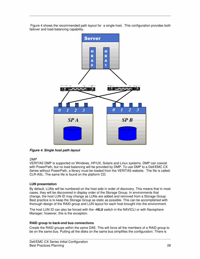
Figure 4 shows the recommended path layout for a single host. This configuration provides bothfailover and load-balancing capability.
Figure 4. Single host path layout
DMPVERITAS DMP is supported on Windows, HP/UX, Solaris and Linux systems. DMP can coexistwith PowerPath, but no load balancing will be provided by DMP. To use DMP to a Dell/EMC CXSeries without PowerPath, a library must be loaded from the VERITAS website. The file is called:CLR-ASL. The same file is found on the platform CD.
LUN presentation
By default, LUNs will be numbered on the host side in order of discovery. This means that in mostcases, they will be discovered in display order of the Storage Group. In environments thatchange, the host LUN ID may change as LUNs are added and removed from a Storage Group.Best practice is to keep the Storage Group as static as possible. This can be accomplished withthorough design of the RAID group and LUN layout for each host brought into the environment.
The host LUN ID can also be forced with the –HLU switch in the NAVICLI or with NavisphereManager; however, this is the exception.
RAID group to back-end bus connections
Create the RAID groups within the same DAE. This will force all the members of a RAID group tobe on the same bus. Putting all the disks on the same bus simplifies the configuration. There is
Dell/EMC CX Series Initial ConfigurationBest Practices Planning 28
Mirrored CacheSP B
0 1 2 3
Mirrored CacheSP A
0 1 2 3
Server
H
B
A
0
H
B
A
1

little performance advantage to splitting the disks across all the buses, so configuring the disksacross all different buses is not worth the added complexity.
Back-end connectivity
Back-end connectivity is controlled by the EMC installer to help minimize complexity andmaximize balance of the number of disks on a pair of back-end buses.
Let Dell/EMC CX Series manage its own back end connectivity.
Clustering
EMC supports several clustering products. Fundamentally, cluster support can be accomplishedon a Dell/EMC CX Series by sharing common LUNs in the Storage Group. If the members of thecluster need their own separate storage, separate Storage Groups must be used and thecommon LUN is put into both Storage Groups. A host can only be in one Storage Group perstorage system, but LUNs can be in multiple Storage Groups. When LUNs are shared betweenthe hosts, it is up to the sharing hosts to manage the data integrity of shared LUNs. Thereforecreate two Storage Groups—one for each host—and put the shared LUNs in both StorageGroups. When selecting the LUNs for the second Storage Group, select all in the show LUNsbox and select the shared LUNs. When you select all a warning informs you that “multiple hosts”will be able to see the LUNs. Click OK. Be sure that the LUNs selected in the Navisphere UI forthe second host’s Storage Group are selected in the same order as the selections in the firsthost’s Storage Group. Selecting the LUNs in a different order may cause problems with thecluster software.
Choose a Storage Group name that reflects the host and cluster name. For example, you mightcall the Storage Group containing the first host in a Sun cluster: Host1-of-Suncluster.
The following sections show the supported cluster software. Cluster software is host or OSbased. Typically cluster software uses local copies of the data and does not participate in remotecopies of the data. Clusters with Dell/EMC CX Series do not typically use Dell/EMC CX Seriesreplication software for heartbeats. Shared disks can be used as heartbeat or mailbox storage,but that does not depend on any Dell/EMC CX Series-specific capability other than shared drives.Heartbeats/mailboxes for the cluster must be shared drives.
Sun clusters
Do not use Sun Cluster if Solaris is booting from the Dell/EMC CX Series.
You must use FC-SW to support OPS, RAC, or greater than two-node clusters.
Some Solaris 9 clustered environments require patches. Refer to the EMC Support Matrix forpatch listings for particular hosts and configurations.
VERITAS clusters
Do not use VERITAS Cluster if Solaris is booting from the Dell/EMC CX Series.
IBM clusters
Two IBM Cluster packages are available to users: HACMP and GPFS.
HACMPBooting from the Dell/EMC CX Series is allowed in HACMP clusters. These boot drives should beonly available to that host.
GPFSGPFS configurations usually span multiple hosts and storage systems to create the parallel filesystems structure. These configurations are usually in the 40–100 TB size range. Multiple
Dell/EMC CX Series Initial ConfigurationBest Practices Planning 29
Dell/EMC CX Seriess can be used to accommodate these configurations. This is consideredoutside the 80 percent rule for best practices. Consultation is required for these configurations.
Windows clusters: Microsoft Cluster Server
Current SCSI port or SCSI miniport drivers cannot share the same path for the boot device as forthe shared cluster devices. As a result, a dedicated adapter is required for each path (if bootingfrom internal disk, it is already on a separate Adapter). For example, each host has its own bootLUN and additional data LUNs that they share. A non-HA configuration requires two HBAs foreach server: one for a dedicated path to the boot device and another for a path to the datadevices. An HA configuration for the data LUNs requires three HBAs each (two data HBA paths).An HA configuration to include the boot LUNs requires four HBAs on each server. Each Serverneeds separate paths: Two HBA paths for the data and two paths for the boot LUN.
Storport can share the same path for the boot device and the shared cluster devices.
Microsoft Windows Server 2000/2003 clusters using Microsoft Cluster Services (MSCS) cannotmake use of dynamic disks. Use metaLUNs and Microsoft’s diskpart utility to provide expandable,striped, and concatenated volumes for these systems.
Linux (RedHat) clusters
Use Enterprise Linux Cluster.
HP TruCluster
Dell/EMC CX Series requires HP TruCluster software.
SCALING: STORAGE SYSTEM SIZES
Dell/EMC CX Series storage systems can be defined many ways. Earlier sections of this whitepaper defined usage profiles. This section defines three systems based on size or capacity. Thesystems are: small, medium and large.
Small storage system
A small storage system consists of one to three DAEs. The first DAE will have Fibre Channeldrives. The other two can be have either ATA/SATA-II or FC drive types.
Medium storage system
A medium storage system ranges in size from four to 11 DAEs, to the maximum being a fullsingle rack.
Large storage system
A large system uses two or three racks, which are added footprints. The large system contains 12to 32 DAEs. The CX3-80 can support up to 480 drives per storage system.
Host connectivity
Environment sizes are defined as follows:
• Small environments have 1 to 10 hosts.
• Medium environments have 11 to 30 hosts.
• Large environment have greater than 31 hosts.
Dell/EMC CX Series Initial ConfigurationBest Practices Planning 30
Exchange environments
Exchange environments are defined by size and load. Size is measured in numbers of users, andload is defined as the number of I/O per second per user.
• Small environments are less than 1,000 users.
• Medium environments have 1,000 to 5,000 users.
• Large environment have greater than 5,000 users.
• Light loads are less than .18 IOPS (OWA and POP3) per user.
• Medium loads consist of .4 to 1 IOPS (Outlook Rich Client) per user.
• Heavy loads consist of greater than .75 IOPS (Outlook Rich Client) per user.
Table 13 provides the recommended storage system configuration based on the Exchangeenvironment and workload. The configurations are defined in the section “S.”
Table 13. Storage system configuration for various Exchange environments andworkloads
Smallenvironments
Mediumenvironments
Large environments
Light loads Small configuration Medium configuration Large configuration
Medium loads Medium configuration Large configuration Large configuration
Heavy loads Tuning required* Tuning required* Tuning required*
* These are exceptions.
Consult the EMC Dell/EMC CX Series Storage Solutions Microsoft Exchange 2003 BestPractices white paper for additional details.
DISK-ARRAY ENCLOSURE (DISK SHELVES)
Availability
Scaling is accomplished on the Dell/EMC CX Series by adding DAEs. DAEs can be added whilethe system is running, but if possible, EMC recommends shutting down the attached hosts to thesystem when making hardware changes to the environment. Hardware changes should becoordinated with EMC service.
Drive types per DAE
Only one type of drive— either Fibre Channel, SATA-II or ATA—can reside in a specific DAE.The first DAE must have only FC drives.
Drives per DAE
A DAE supports up to 15 drives. EMC does not require any drives in a DAE, other than in the firstDAE. EMC recommends a minimum of four drives per DAE.
Drive types per storage system
EMC recommends matching the drive type to the type of application environment. The first traymust contain Fibre Channel drives.
Dell/EMC CX Series Initial ConfigurationBest Practices Planning 31
Drives per RAID group
Select 5, 9, 2, or 1 for the number of drives per RAID group.
� 5= 4+1 RAID 5
� 9 = 8+1 RAID 5
� 2 = 1+1 RAID 1 or RAID 1/0
� 1 = Hot spare
Cabinets
A second cabinet is required once a total of 11 DAEs has been reached.
A third cabinet is required once a total of 13 DAEs has been reached in the second cabinet.
CONCLUSION
This white paper describes the Dell/EMC CX Series storage system and the connection settingsthat satisfy 80 percent of the Dell/EMC CX Series environments. This is a recommendations orbest practices document— not a requirements document. It is also a living document, whichmeans that as better settings are discovered, changes will be made to the document.
REFERENCES
Replication software
Several replication software applications run on Dell/EMC CX Series. The following list of bestpractices papers address the special capabilities of replication software. Consult the appropriatepaper for the replication software being used.
Replication Manager and SnapView for Replication on Dell/EMC CX Series Storage Arrays - BestPractices Planning
Dell/EMC CX Series Reserved LUN Pool Configuration Considerations for SnapView, SAN Copy,and MirrorView/Asynchronous
EMC Dell/EMC CX Series SnapView Clones - A Detailed Review
EMC Dell/EMC CX Series SAN Copy - A Detailed Review
EMC Dell/EMC CX Series MirrorView/Asynchronous Disaster Recovery Software
MirrorView Knowledgebook: CX Series FLARE 19 and CX3 Series FLARE 22 - AppliedTechnology
Other references
EMC Dell/EMC CX Series Best Practices for Fibre Channel Storage on EMC Powerlink
EMC Dell/EMC CX Series Storage Solutions Microsoft Exchange 2003 Best Practices on EMCPowerlink
EMC Dell/EMC CX Series Data Replication Scenarios for Oracle Deployments - TechnologyConcepts and Business Considerations on EMC Powerlink
SQL Server Data Warehouse Deployments with EMC Dell/EMC CX Series Storage SystemsApplied Technology White Paper on EMC Powerlink
Dell/EMC CX Series Initial ConfigurationBest Practices Planning 32
The information contained in this document, including all instructions, cautions, and regulatoryapprovals and certifications, is provided by EMC Corporation and has not been independently verifiedor tested by Dell. Dell cannot be responsible for damage caused as a result of either following orfailing to follow these instructions. All statements or claims regarding the properties, capabilities,speeds or qualifications of the part referenced in this document are made by EMC and not by Dell.Dell specifically disclaims knowledge of the accuracy, completeness or substantiation for any suchstatements. All questions or comments relating to such statements or claims should be directed toEMC Corporation.
Dell/EMC CX Series Initial ConfigurationBest Practices Planning 33