DELL EQUALLOGIC PS SERIES NETWORK...
21
TECHNICAL REPORT DELL EQUALLOGIC PS SERIES NETWORK PERFORMANCE GUIDELINES ABSTRACT This Technical Report describes network configuration requirements and recommendations for high performance and reliability with a PS Series group. TR1017 V4.0
-
Upload
truongdiep -
Category
Documents
-
view
222 -
download
3
Transcript of DELL EQUALLOGIC PS SERIES NETWORK...

TECHNICAL REPORT
DELL EQUALLOGIC PS SERIES NETWORK PERFORMANCE GUIDELINES ABSTRACT This Technical Report describes network configuration requirements and recommendations for high performance and reliability with a PS Series group.
TR1017
V4.0


ii PS Series Groups: Network Performance Guidelines
Copyright © 2009 Dell Inc. All Rights Reserved.
Dell EqualLogic is a trademark of Dell Inc.
All trademarks and registered trademarks mentioned herein are the property of their respective owners.
Possession, use, or copying of the documentation or the software described in this publication is authorized only under the license agreement specified herein.
Dell, Inc. will not be held liable for technical or editorial errors or omissions contained herein. The information in this document is subject to change.
June 2009
WWW.DELL.COM/PSseries
iii PS Series Groups: Network Performance Guidelines
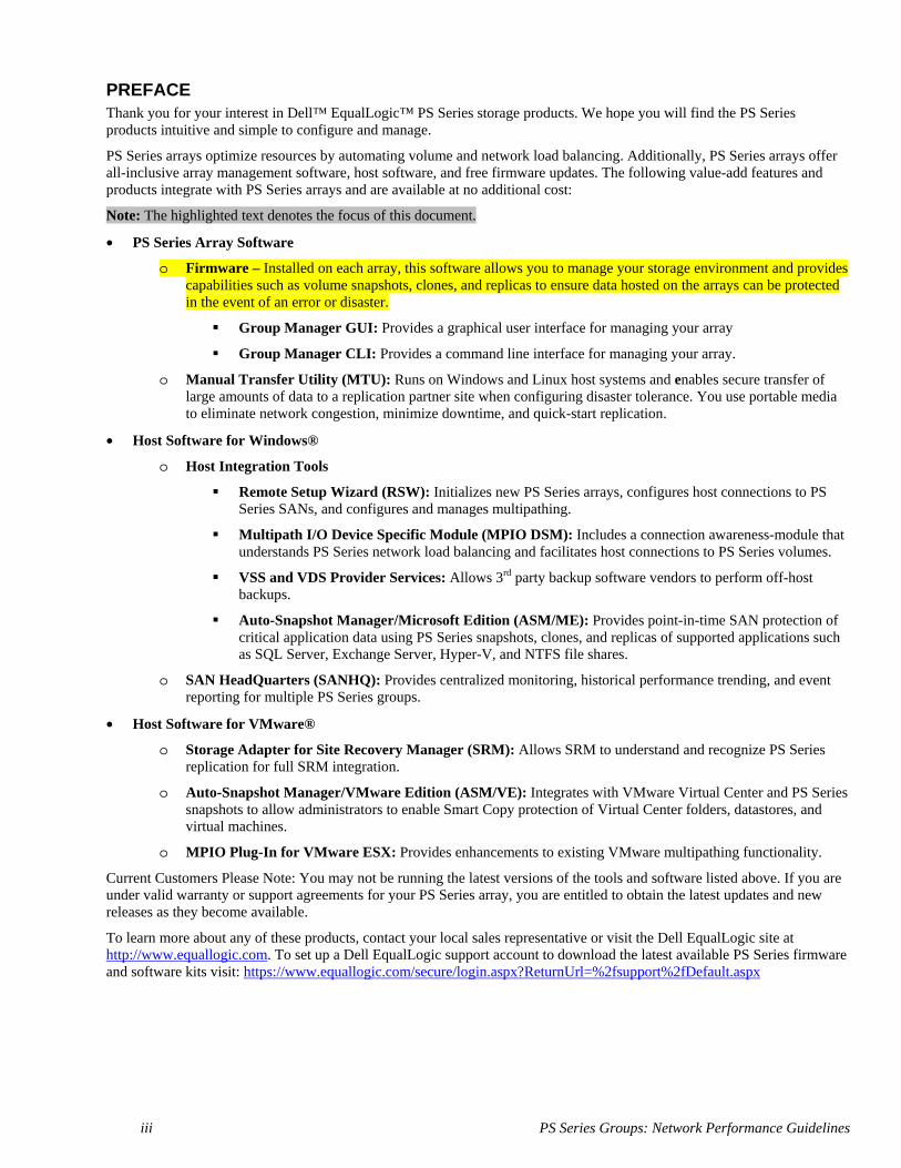
PREFACE Thank you for your interest in Dell™ EqualLogic™ PS Series storage products. We hope you will find the PS Series products intuitive and simple to configure and manage.
PS Series arrays optimize resources by automating volume and network load balancing. Additionally, PS Series arrays offer all-inclusive array management software, host software, and free firmware updates. The following value-add features and products integrate with PS Series arrays and are available at no additional cost:
Note: The highlighted text denotes the focus of this document.
• PS Series Array Software
o Firmware – Installed on each array, this software allows you to manage your storage environment and provides capabilities such as volume snapshots, clones, and replicas to ensure data hosted on the arrays can be protected in the event of an error or disaster.
Group Manager GUI: Provides a graphical user interface for managing your array
Group Manager CLI: Provides a command line interface for managing your array.
o Manual Transfer Utility (MTU): Runs on Windows and Linux host systems and enables secure transfer of large amounts of data to a replication partner site when configuring disaster tolerance. You use portable media to eliminate network congestion, minimize downtime, and quick-start replication.
• Host Software for Windows®
o Host Integration Tools
Remote Setup Wizard (RSW): Initializes new PS Series arrays, configures host connections to PS Series SANs, and configures and manages multipathing.
Multipath I/O Device Specific Module (MPIO DSM): Includes a connection awareness-module that understands PS Series network load balancing and facilitates host connections to PS Series volumes.
VSS and VDS Provider Services: Allows 3rd party backup software vendors to perform off-host backups.
Auto-Snapshot Manager/Microsoft Edition (ASM/ME): Provides point-in-time SAN protection of critical application data using PS Series snapshots, clones, and replicas of supported applications such as SQL Server, Exchange Server, Hyper-V, and NTFS file shares.
o SAN HeadQuarters (SANHQ): Provides centralized monitoring, historical performance trending, and event reporting for multiple PS Series groups.
• Host Software for VMware®
o Storage Adapter for Site Recovery Manager (SRM): Allows SRM to understand and recognize PS Series replication for full SRM integration.
o Auto-Snapshot Manager/VMware Edition (ASM/VE): Integrates with VMware Virtual Center and PS Series snapshots to allow administrators to enable Smart Copy protection of Virtual Center folders, datastores, and virtual machines.
o MPIO Plug-In for VMware ESX: Provides enhancements to existing VMware multipathing functionality.
Current Customers Please Note: You may not be running the latest versions of the tools and software listed above. If you are under valid warranty or support agreements for your PS Series array, you are entitled to obtain the latest updates and new releases as they become available.
To learn more about any of these products, contact your local sales representative or visit the Dell EqualLogic site at http://www.equallogic.com. To set up a Dell EqualLogic support account to download the latest available PS Series firmware and software kits visit: https://www.equallogic.com/secure/login.aspx?ReturnUrl=%2fsupport%2fDefault.aspx

iv PS Series Groups: Network Performance Guidelines
TABLE OF CONTENTS Preface .................................................................................................................................. iii Revision Information ............................................................................................................. v Introduction ............................................................................................................................ 1 Network Ports and Protocols ................................................................................................. 1
Required Ports and Protocols .......................................................................................... 1 Optional Ports and Protocols .......................................................................................... 1
Hardware Configuration Recommendations.......................................................................... 3 Redundant Network Connections ................................................................................... 3 Control Module Failover ................................................................................................ 3 Redundant Network Switches ......................................................................................... 3
Network Requirements and Recommendations ..................................................................... 4 Spanning-Tree Protocol .................................................................................................. 6 Flow Control ................................................................................................................... 6 Unicast Storm Control .................................................................................................... 7 Jumbo Frames ................................................................................................................. 7 VLANs ............................................................................................................................ 8 Quality of Service (QoS) ................................................................................................ 8
Network Hardware Configurations ........................................................................................ 9 Configuring a Network Interface ......................................................................................... 12 Technical Support and Customer Service ............................................................................ 14

v PS Series Groups: Network Performance Guidelines
REVISION INFORMATION The following table describes the release history of this Technical Report.
Report Date Document Revision
1.0 April 2005 Initial Release for PS Firmware Version 2.0 2.0 September 2006 Updated for PS Firmware Version 3.0 3.0 June 2008 Update with improved network guidelines 4.0 June 2009 Updated for PS Firmware Version 4.1; added protocol tables.
The following table shows the software and firmware used for the preparation of this Technical Report.
Vendor Model Software Revision
Dell EqualLogic All PS Series Firmware Version 4.1
The following table lists the documents referred to in this Technical Report. All PS Series Technical Reports are available on the Customer Support site at: support.dell.com
Vendor Document Title
-N/A-


1 PS Series Groups: Network Performance Guidelines
INTRODUCTION
A PS Series group is an iSCSI SAN consisting of one or more PS Series storage arrays (group members) connected to an IP network and managed as a single system. This Technical Report provides network requirements and performance recommendations for a PS Series group.
Detailed network configuration guidelines are beyond the scope of this document. All the usual rules for proper network configuration apply to the members (arrays) in a PS Series group.
NETWORK PORTS AND PROTOCOLS PS Series groups use a number of TCP and UDP protocols for group management, I/O operations, and internal communication. If you have switches or routers set to block these protocols, you may need to unblock them to allow management or I/O operations to work correctly. The required and optional protocols are listed in the following sections.
Required Ports and Protocols The protocols for iSCSI and inter-array communication are mandatory, and the group cannot function without them.
iSCSI Protocol Table 1 lists the iSCSI protocol, which is used between the iSCSI initiator and the PS Series group.
Table 1: iSCSI Protocols
Type Port Protocol Access
TCP 3260 iSCSI To the group IP address and all individual member IP addresses
EqualLogic Internal Protocols Table 2 lists the internal protocols that PS Series group members use to communicate with one another.
Table 2: EqualLogic Internal Protocols Type Port Protocol Access UDP 161 SNMP Management operations TCP 9876 Internal iSCSI intra-system control TCP 25555 Internal Group communication TCP 20002 Internal Event logging TCP 20003 Internal Internal event querying
Optional Ports and Protocols The following protocols, for management and alerts, are optional and depend on your management needs and security requirements. They are not required for correct array operation.
2 PS Series Groups: Network Performance Guidelines
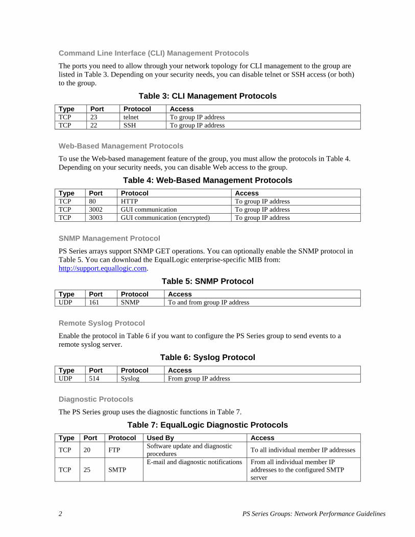
Command Line Interface (CLI) Management Protocols The ports you need to allow through your network topology for CLI management to the group are listed in Table 3. Depending on your security needs, you can disable telnet or SSH access (or both) to the group.
Table 3: CLI Management Protocols Type Port Protocol Access TCP 23 telnet To group IP address TCP 22 SSH To group IP address
Web-Based Management Protocols To use the Web-based management feature of the group, you must allow the protocols in Table 4. Depending on your security needs, you can disable Web access to the group.
Table 4: Web-Based Management Protocols Type Port Protocol Access TCP 80 HTTP To group IP address TCP 3002 GUI communication To group IP address TCP 3003 GUI communication (encrypted) To group IP address
SNMP Management Protocol PS Series arrays support SNMP GET operations. You can optionally enable the SNMP protocol in Table 5. You can download the EqualLogic enterprise-specific MIB from: http://support.equallogic.com.
Table 5: SNMP Protocol Type Port Protocol Access UDP 161 SNMP To and from group IP address
Remote Syslog Protocol Enable the protocol in Table 6 if you want to configure the PS Series group to send events to a remote syslog server.
Table 6: Syslog Protocol Type Port Protocol Access UDP 514 Syslog From group IP address
Diagnostic Protocols The PS Series group uses the diagnostic functions in Table 7.
Table 7: EqualLogic Diagnostic Protocols Type Port Protocol Used By Access
TCP 20 FTP Software update and diagnostic procedures To all individual member IP addresses
TCP 25 SMTP E-mail and diagnostic notifications From all individual member IP
addresses to the configured SMTP server

3 PS Series Groups: Network Performance Guidelines
HARDWARE CONFIGURATION RECOMMENDATIONS At a minimum, an array needs one network interface (Ethernet port) on one (active) control module connected to a network switch to provide connectivity between the array and the network. By default, when setting up a group or adding a member to a group, you configure Ethernet 0 on an array.
However, this is a single-point-of-failure configuration, and does not provide the best performance. A failure of the control module, the connected network interface, or the network switch will cause the array and any volumes with data on the array to be set offline. An array should not run in a minimum configuration for any length of time.
You can improve availability and performance by implementing the following recommendations:
• Use redundant network connections to provide interface failover • Use two control modules to provide control module failover • Use redundant network switches to provide switch failover
Redundant Network Connections To protect against a network interface failure and increases performance (network bandwidth), connect more than one network interface (Ethernet port) on a control module to a network.
For example, if you connect Ethernet 0 and Ethernet 1 on a control module to a network, then if Ethernet 0 fails, the traffic is automatically redirected to Ethernet 1 with no disruptions.
Recommendation: Connect all the iSCSI network interfaces (varies by array and control module model) to a network switch.
Control Module Failover To protect against control module failure, install a second control module and connect it to the network. If the active control module fails, the secondary control module becomes active with no disruptions.
Most PS Series arrays are shipped with two control modules of the same type. If your array has only one control module, you can order and install a second one (must be of the same type).
Note: Properly connected network cables are vital to array and group operation and performance. If you have a dual control module array, it is especially important that you use the correct cable configuration to take advantage of the array’s failover capabilities. For the highest performance and availability, follow the network cable connection recommendations described in the Hardware Maintenance manual for your array model.
Recommendation: Install a second control module and connect the ports for all the configured network interfaces to the network.
Redundant Network Switches For the best availability, failure protection and performance, distribute network connections across different network switches.
Recommendation: Connect all the configured network interfaces on both control modules to multiple network switches that are connected with interswitch links.

4 PS Series Groups: Network Performance Guidelines
NETWORK REQUIREMENTS AND RECOMMENDATIONS The networking requirements for group members are described in Table 8 (for hardware) and Table 9 (for software). Many of these requirements are described in more detail in later sections.
Table 8: Hardware Requirements and Recommendations
Item Description
Ethernet network Required: Ethernet network.
Recommended: Switched Gigabit Ethernet network.
Reason: Although an array can operate at 10 or 100 Megabits, performance will be slower than when using a Gigabit Ethernet switch.
Network connections Required: One configured, functioning, and enabled network interface on the active control module connected to the network.
Recommended: Connect, configure, and enabled all the network interfaces eligible for iSCSI traffic.
Reason: Improves availability and performance.
Note: The Group Manager GUI uses network ports 80, 3002, and 3003.
Control modules Required: One functioning control module per array.
Recommended: Install a second control module (if applicable) and connect the ports for all the configured network interfaces to the network.
Reason: Enables continued operation when one control module in an array fails.
Switches Required: Any standard Ethernet switch will work with a PS Series group.
Recommended: Distribute network connections across one or more switches, connected using interswitch links that have sufficient bandwidth to handle the iSCSI traffic.
Reason: Improves network availability and performance.
Note: When selecting a switch, performance is the most important consideration. Note that not all Gigabit Ethernet switches can run all ports at line speed.
Redundant network paths between computers and arrays
Required: (N/A)
Recommended: Configure redundant network paths between computers and arrays.
Reason: A multipathing solution helps to ensure that no single point of failure exists between hosts and arrays.

5 PS Series Groups: Network Performance Guidelines
Item Description
Network link for replication
Required: Network connection between two groups configured as replication partners. Make sure that the network link between the partners is reliable and provides sufficient bandwidth for copying data.
Reason: To ensure effective and predictable replication. (If network replication is not available, you can use the Manual Transfer Utility. See the support site for more information.)
Note: An array uses the standard iSCSI port 3260 to transmit iSCSI traffic.
Table 9: Software Requirements and Recommendations
Item Description
Group IP address connectivity
Requirement: In a multi-subnet group, each member must have at least one network interface on the same subnet as the group IP address and the group management address (if configured).
Default gateway (optional)
Network address for the device used to connect subnets and forward network traffic beyond the local network. Needed only if you want the array network interface to communicate outside the local network (for example, to allow access to volumes from computers outside the local network). Note: The default gateway must be on the same subnet as the array network interface.
Spanning-Tree Protocol (STP)
If possible, do not use STP on switch ports that connect end nodes (iSCSI initiators or storage array network interfaces).
However, if you must use STP or RSTP (preferable to STP), you should enable the port settings (available on some switches) that let the port immediately transition into STP forwarding state upon linkup. This functionality can reduce network interruptions that occur when devices restart, and should only be enabled on switch ports that connect end nodes.
You can use Spanning-Tree for a single-cable connection between switches, and you can use trunking for multi-cable connections between switches.
See Spanning-Tree Protocol on page 6 for more information.
Flow Control Enable Flow Control on each switch port and NIC that handles iSCSI traffic. PS Series storage arrays will correctly respond to Flow Control.
See Flow Control on page 6 for more information.
Unicast storm control Disable unicast storm control on each switch that handles iSCSI traffic if the switch provides this feature. However, the use of broadcast and multicast storm control is encouraged on switches.
See Unicast Storm Control on page 7 for more information.
Jumbo Frames Enable Jumbo Frames on each switch and NIC that handles iSCSI traffic.
See Jumbo Frames on page 7 for more information.

6 PS Series Groups: Network Performance Guidelines
Item Description
VLANs Configure switches to use VLANs to separate iSCSI SAN traffic from other network traffic.
See VLANs on page 8 for more information.
Quality of Service (QoS)
Do not use QoS rules on your network switch, as it can have unintended and undesirable consequences when used with iSCSI traffic. You can use QoS on the wide-area network.
See Quality of Service (QoS) on page 8 for more information.
Spanning-Tree Protocol Spanning-Tree Protocol (STP, defined in the IEEE 802.1d specification), is a link management protocol that prevents loops in an Ethernet network by ensuring that only one active path exists between switches. Upon linkup, a switch performs a 30 to 50 second or longer STP calculation to transition ports into forwarding or blocking state. During this time, no user data passes through the ports, resulting in a longer time for links to come online.
Because STP can increase the time it takes to recover from a PS Series array control module failover or a network switch failure, Dell recommends that you do not use STP on switch ports that connect end nodes (iSCSI initiators or storage array network interfaces).
Note: Dell encourages the use of STP for a single-cable connection between switches, and the use of trunking for multi-cable connections between switches.
If you must use STP, Dell recommends that you enable the switch port settings that allow the immediate transition of the port into STP forwarding state upon linkup. This functionality—not available on all switches—can reduce network interruptions that occur when devices restart. For example, Cisco enhanced the original STP 802.1d specification with a proprietary feature called PortFast, which immediately transitions a port into STP forwarding state upon linkup.
The settings should be enabled only on switch ports that connect end nodes (iSCSI initiators and storage array network interfaces). Do not connect other hubs, switches, concentrators, or bridges to these ports, because this may cause infinite packet loops.
It is also preferable to use Rapid Spanning Tree Protocol (RSTP, defined in the IEEE 802.1w specification) instead of STP. RSTP allows a switch port to bypass the Spanning-Tree listening and learning states and quickly enter the STP forwarding state. To achieve fast convergence on a port, RSTP relies upon two variables: edge ports and link type. Switch ports connecting end nodes (iSCSI initiators and storage array network interfaces) should be configured as edge ports to take advantage of RSTP features.
See your switch documentation for more information on STP.
Flow Control On many networks, there can be an imbalance in the network traffic between the devices that send traffic and the devices that receive the traffic. This is often the case in SAN configurations in which many servers (initiators) are communicating with storage devices (targets). If senders transmit data simultaneously, they may exceed the throughput capacity of the receiver. When this occurs, the receiver may drop packets, forcing senders to retransmit the data after a delay. Although this will

7 PS Series Groups: Network Performance Guidelines
not result in any loss of data, latency will increase because of the retransmissions, and I/O performance will degrade. Flow Control helps to eliminate this problem. When enabled, Flow Control allows the receiver to instruct the sender to “throttle back” when the receiver senses that it is being overwhelmed by packets. The receiver does this by sending “pause frames” to the sender, which causes the sender to slow packet transmission for a short period of time. This lets the receiver process its backlog so it can later resume accepting input. The amount of delay introduced by this action is dramatically less than the overhead caused by TCP/IP packet retransmission. Dell recommends that you enable Flow Control on the switch ports that handle iSCSI traffic. If a server is using a software iSCSI initiator and NIC combination to handle iSCSI traffic, you must also enable Flow Control on the NICs to obtain any performance benefit. PS Series storage arrays will automatically correctly respond to Flow Control. See your switch and NIC documentation for information about enabling Flow Control.
Unicast Storm Control A traffic “storm” occurs when a large outpouring of packets creates excessive network traffic that degrades network performance. Many switches have traffic storm control features that prevent ports from being disrupted by broadcast, multicast, or unicast traffic storms on physical interfaces. These features typically work by discarding network packets when the traffic on an interface reaches a percentage of the overall load (usually 80 percent, by default). Because iSCSI traffic is unicast traffic and can typically use the entire link, Dell recommends that you disable unicast storm control on switches that handle iSCSI traffic. However, you can use broadcast and multicast storm control on switches. See your switch documentation for information on disabling unicast storm control.
Note: Not all switches provide unicast storm control functionality.
Jumbo Frames Ethernet traffic is transported in frames. A standard Ethernet frame allows up to 1500 bytes of data to be transferred in a single Ethernet transaction. Jumbo Frames extend Ethernet frames to 9000 bytes and allow more data to be transferred with each Ethernet transaction. Jumbo Frames help reduce the interrupt overhead on the server. PS Series storage arrays support standard Ethernet frames and Jumbo Frames up to 9000 bytes (9018 including the TCP header itself). This is sometimes referred to as the “Alteon standard.” PS Series storage arrays also support path MTU, which is the ability to automatically detect the maximum frame size between TCP/IP end points. Dell recommends that you enable Jumbo Frames on each switch that handles iSCSI traffic. If your server is using a software iSCSI initiator and NIC combination to handle iSCSI traffic, you must also enable Jumbo Frames on the NICs to obtain any performance benefit and ensure consistent behavior. To simplify troubleshooting initial deployments, make sure that your iSCSI initiator, switches, and storage arrays are fully operational before enabling Jumbo Frames on the NICs.
Note: To obtain a performance benefit with Jumbo Frames and ensure consistent behavior, all devices in the network path between servers and the PS Series group⎯including the switches and the NICs used for iSCSI traffic⎯must have Jumbo Frames enabled. Switches configured for Jumbo Frames will support both standard Ethernet frames and Jumbo Frames. However, if a NIC is configured for Jumbo Frames, but the switch is not,

8 PS Series Groups: Network Performance Guidelines
you may experience inconsistent behavior. For example, the switch will function properly if the frames are small, but once the NIC attempts to send frames larger than 1500 bytes, the switch will not be able to handle the frames and will drop them. Also, if some switches are configured for Jumbo Frames, but others are not, you may experience inconsistent behavior if routing changes occur after the connection has been established.
Many low and mid-range network switches do not support Jumbo Frames. On switches that do support them, the feature is usually disabled by default, so you need to manually enable it. Usually, VLANs must be configured in order to enable Jumbo Frames on switches. See your switch documentation for details. Every initiator connection has a corresponding event message. The message indicates whether the connection is using standard or Jumbo Frames. Use the Group Manager GUI to look for connections with standard frames.
VLANs VLANs provide performance a benefit similar to those of separate network switches, but with fewer physical switches and less management overhead. Because VLANs use logical rather than physical connections, they are flexible to operate.
Using VLANs to separate iSCSI SAN traffic from LAN traffic also allows you to enable switch-based security enhancements, including port blocking and address filtering, on some switches.
Dell recommends that you configure virtual LANs (VLANs) on your switches to separate iSCSI SAN traffic from other network traffic.
Typically, VLANs are separate subnets in TCP/IP networks, so connectivity between VLANs usually requires L3 routing, which is not supported by all switches. VLANs also support different network settings, including Jumbo Frames.
Note: PS Series storage arrays do not support VLAN tagging.
See your switch documentation for information on configuring VLANs.
Quality of Service (QoS) Quality of service is described as either of the following:
• The ability to provide different priority levels to different applications, users, or data flows, or to guarantee a certain level of performance to a data flow.
• A network function implemented in some routers and switches that provides high priority for certain types of latency-sensitive traffic (for example, VoIP) and lower priority for other types of traffic (for example, web or http).
The type of traffic is often identified by the TCP/IP port it comes from. In networking terms, this corresponds to a protocol or application. Applications can support more than one protocol–for example, a web browser can send http, https, and ftp traffic through different ports. This is how the computer knows to send web traffic (using an IP address) to a browser (http uses port 80), and file sharing traffic (using CIFS) to Windows Explorer (ports 137, 138, and 139).
Quality of service guarantees are important if the network capacity is insufficient, and in networks where the capacity is a limited resource. In the absence of network congestion, QoS mechanisms are not required.

9 PS Series Groups: Network Performance Guidelines
A “best-effort” network or service does not support quality of service. With best-effort delivery service, a single bandwidth-intensive application can result in poor or unacceptable performance for all applications.
Network administrators might use QoS to guarantee throughout for mission-critical applications so that their transactions are processed in an acceptable amount of time.
PS Series arrays are designed to provide I/O as fast as your network can support it. Therefore, using QoS with iSCSI traffic does not produce expected or desirable results on the SAN. Also, QoS rules can affect how well–or even whether–replication succeeds between PS Series groups.
If you plan to use QoS, Dell recommends that you use it only on VLANs that do not carry iSCSI traffic, or on WANs, where bandwidth is shared with other applications and the PS Series array uses it for time-insensitive replication traffic. Dell recommends against using QoS on the SAN.
NETWORK HARDWARE CONFIGURATIONS A PS Series storage array must have at least one active network connection. Multiple network connections are strongly recommended for performance and availability.
See the Hardware Maintenance manual for your array model for detailed information about connecting network cables.
Figure 1 shows the recommended network configuration for single control module array with four iSCSI interfaces. If any one Ethernet port fails, initiators can be redirected to another Ethernet port. However, this configuration has two different single points of failure: the control module and the switch.
Figure 1: Single Control Module and Single Switch

10 PS Series Groups: Network Performance Guidelines
To provide failover for the switch, connect the Ethernet ports on the control module to different switches, connected with interswitch links, as shown in Figure 2. However, the control module is still a single point of failure.
Figure 2: Recommended Configuration for Single Control Module
Figure 3 shows the network configuration for a dual control module array and a single network switch. This configuration protects against the failure of a control module or a network interface, but not against the failure of the network switch.
Figure 3: Dual Control Modules and Single Switch

11 PS Series Groups: Network Performance Guidelines
Figure 4 shows the recommended network configuration for a dual control module array. This configuration provides the highest network availability, protection against the failure of a control module, an interface port, or a switch, and the maximum network bandwidth.
Figure 4: Recommended Configuration for Dual Control Modules
Figure 5 shows the recommended network configuration for a dual control module array that has a configured dedicated management network. The figure shows the management network on a separate physical switch; however, it can be configured on a VLAN on the same switches that carry the iSCSI traffic.
Figure 5: Recommended Configuration with Management Network

12 PS Series Groups: Network Performance Guidelines
CONFIGURING A NETWORK INTERFACE
After connecting a network interface to a network, as described in the Hardware Maintenance manual for your PS Series array model, you can configure the interface by assigning it an IP address and subnet mask. You can also modify an existing network interface configuration.
Note: Changing the IP address for a functioning network interface will disconnect all iSCSI initiators that are connected to that interface. However, all initiators should reconnect automatically.
1. To configure a network interface using the GUI, click:
Members → member_name → Network tab
The Member Network window appears, displaying the current network configuration for each network interface on the member. As shown in theFigure 6, eth2 (Ethernet Port 2) does not have an IP address assigned.
Figure 6: Member Network
2. Double-click the network interface in the IP Configuration panel
The Modify IP Settings dialog box appears (Figure 7).

13 PS Series Groups: Network Performance Guidelines
Figure 7: Modify IP Settings
3. Specify the following information about the network interface, then click OK:
• IP address. You must specify an IP address. In a multi-subnet group, each member must have at least one network interface that is on the same subnet as the group IP address.
• Subnet mask. You must specify a subnet mask (netmask) for the IP address.
• Default gateway. The default gateway is the same for all network interfaces on an array. You cannot modify the default gateway using the Modify IP Settings dialog box.
• Enable this interface. Click the checkbox to enable the interface. It starts to be used as soon as you click OK.
• Restrict to management interface. Leave the box unchecked. This setting applies only if you have already configured a dedicated management network, connected the cables appropriately, and want to use the interface only for group management traffic. See the Group Administration manual for more information.
You can also use the CLI to configure a network interface and set its status to up or down: member select member_name eth select port ipaddress ip_address netmask mask_ip
member select member_name eth select port up
Note: Depending on your control module type, you will have up to four port variables. On certain models, not all ports can be configured for iSCSI traffic. See the documentation for your array model for more information.
The following examples assign an IP address and netmask to eth2, and enable it for use: > member select lab23 eth select 2 ipaddress 152.17.2.144 netmask 255.255.255.0
> member select lab23 eth select 2 up

14 PS Series Groups: Network Performance Guidelines
TECHNICAL SUPPORT AND CUSTOMER SERVICE Dell’s support service is available to answer your questions about PS Series arrays. If you have an Express Service Code, have it ready when you call. The code helps Dell’s automated-support telephone system direct your call more efficiently.
Contacting Dell Dell provides several online and telephone-based support and service options. Availability varies by country and product, and some services may not be available in your area.
For customers in the United States, call 800-945-3355.
Note: If you do not have an Internet connection, you can find contact information on your purchase invoice, packing slip, bill, or Dell product catalog.
To contact Dell for sales, technical support, or customer service issues:
1. Visit support.dell.com.
2. Verify your country or region in the Choose A Country/Region drop-down menu at the bottom of the window.
3. Click Contact Us on the left side of the window.
4. Select the appropriate service or support link based on your need.
5. Choose the method of contacting Dell that is convenient for you.
Online Services You can learn about Dell products and services on the following websites:
• www.dell.com/
• www.dell.com/ap/ (Asian/Pacific countries only)
• www.dell.com/jp (Japan only)
• www.euro.dell.com (Europe only)
• www.dell.com/la (Latin American countries)
• www.dell.ca (Canada only)
You can access Dell Support through the following websites:
• support.dell.com
• support.dell.com/EqualLogic
• support.jp.dell.com (Japan only)
• support.euro.dell.com (Europe only)