Integrating EqualLogic PS6x10 Arrays with Existing...
19
Integrating EqualLogic PS6x10 Arrays with Existing SANs A Dell Technical White Paper Del l ™ EqualLogic ™ Storage Systems
Transcript of Integrating EqualLogic PS6x10 Arrays with Existing...
Integrating EqualLogic PS6x10 Arrays with Existing SANs A Dell Technical White Paper
Dell™ EqualLogic™ Storage Systems

Integrating EqualLogic™ PS6x10 Arrays with Existing SANs
Page ii
THIS WHITE PAPER IS FOR INFORMATIONAL PURPOSES ONLY, AND MAY CONTAIN TYPOGRAPHICAL ERRORS AND TECHNICAL INACCURACIES. THE CONTENT IS PROVIDED AS IS, WITHOUT EXPRESS OR IMPLIED WARRANTIES OF ANY KIND.
© 2010 Dell Inc. All rights reserved. Reproduction of this material, in any manner whatsoever, without the express written permission of Dell Inc, is strictly forbidden. For more information, contact Dell Inc.
Dell, the DELL logo, and the DELL badge, PowerConnect, EqualLogic and PowerVault are trademarks of Dell Inc.
All other trademarks are owned by their respective companies.
Integrating EqualLogic™ PS6x10 Arrays with Existing SANs
Page 1
Table of Contents
1 Introduction ........................................................................................................ 2
2 Ten Gigabit Ethernet Technology Overview ................................................................... 2
2.1 What is 10Gb Ethernet? .................................................................................... 2
2.2 How is this different from Data Center Bridging? ...................................................... 3
3 Integrating 10Gb PS Series Arrays ............................................................................... 4
3.1 The Starting Point ........................................................................................... 4
3.2 Strategies for Integrating 10Gb Switches ............................................................... 6
3.2.1 Replacing Existing 1GbE SAN Components ........................................................... 6
3.2.2 Integrate 10Gb w/ existing 1Gb ....................................................................... 7
3.3 Preparing the Network Infrastructure ................................................................... 7
3.3.1 10Gb Switches ............................................................................................ 8
4 Mixed Speed SAN Infrastructure ................................................................................ 10
4.1 Terminology ................................................................................................. 10
4.2 Recommended Connection Strategies .................................................................. 11
4.2.1 Attaching a single 10GbE Array to Existing 1GbE Modular Switches ............................ 11
4.2.2 Adding 10GbE Blades to Existing 1GbE Chassis Switches .......................................... 12
4.2.3 Adding Dedicated 10GbE Switches to the 1GbE Infrastructure .................................. 12
4.3 What About Blades? ........................................................................................ 16
5 Conclusion ......................................................................................................... 17
Integrating EqualLogic™ PS6x10 Arrays with Existing SANs
Page 2
1 Introduction With the introduction of 10Gb Ethernet-based EqualLogic™ PS 6x10 series of iSCSI arrays, administrators need to determine what is the best way to take advantage of this high performing storage solution. Should they build out separate storage area network (SAN) groups for their 10 gigabit arrays, or can they integrate their new arrays into their existing 1 gigabit EqualLogic SAN group.
Leveraging Dell’s award winning EqualLogic PS Series SAN array technology, the 10Gb Ethernet-based PS6010 and PS6510 series of arrays provide a scalable, high-performance, tiered storage solution to meet almost any application requirement. This paper describes strategies and best practices for integrating and managing the 10 gigabit Ethernet (10GbE) PS Series arrays into existing EqualLogic SANs consisting of one gigabit Ethernet (1GbE) PS Series arrays. While the recommendations described here are not the only possible architecture options, they are options that can provide the flexibility to grow the SAN as needed while continuing to leverage existing server and storage resources as administrators migrate to newer 10GbE solutions.
As a basis for the ensuing discussion, we will first review the 10GbEstandard and how 10GbE is different from future Enhanced Ethernet standards. Next, we will describe a basic 1GbE networked storage environment that consists of Dell™ PowerEdge™ Servers with 1GbE host adapters connected to an existing EqualLogic SAN group consisting of 1GbE switches and PS Series arrays. We will then discuss the requirements, recommendations and procedures for introducing 10GbE infrastructure components into the existing SAN switching infrastructure, integration of 10GbE PS Series into the existing EqualLogic SAN Group and finally adding 10GbE hosts to the SAN.
2 Ten Gigabit Ethernet Technology Overview
2.1 What is 10Gb Ethernet? Ethernet has been around since the mid 1970’s. Over that time, it has transformed itself in many areas including speed – moving from 1Mbps, 10Mbps, 100Mbps and then to 1Gbps – as well as in terms of features and functionality by adding extensions such as moving from a broadcast, bus architecture to a switched architecture, implementing vLANs, jumbo frames and full-duplex communications among many other innovations. Most of these features and improvements have been managed by the IEEE standards body and its 802 Working Group.
So, how is 10GbE different from the current implementation of the 1Gb Ethernet standard...other than speed? Not as much as you would probably think. At its core, 10GbE is still based on IEEE 802.3, the main standard for Ethernet. In its current implementation, the 802.3ae and later the 802.3an standards define how 10GbE must be implemented. In general, 10GbE added a new physical connection interface called SFP+ as well as introducing a 10Gbase-T standard along with more stringent cabling standards. Last, 10GbE now supports full-duplex communications only as opposed to half-duplex or shared, collision detection implementations.
The objectives for 10GbE had to meet the following requirements:
Preserve the 802.3 frame format Preserve the minimum and maximum frame size limitations Support forwarding between various speeds of previous Ethernet implementations…including
10Mbps Ethernet
Integrating EqualLogic™ PS6x10 Arrays with Existing SANs
Page 3
Support Full Duplex only (no CSMA/CD, or half-duplex) Support ISO 11801 media (Category 6A and Category 7 copper) Provide multiple Physical Layer implementations such as LR, SR fiber and copper
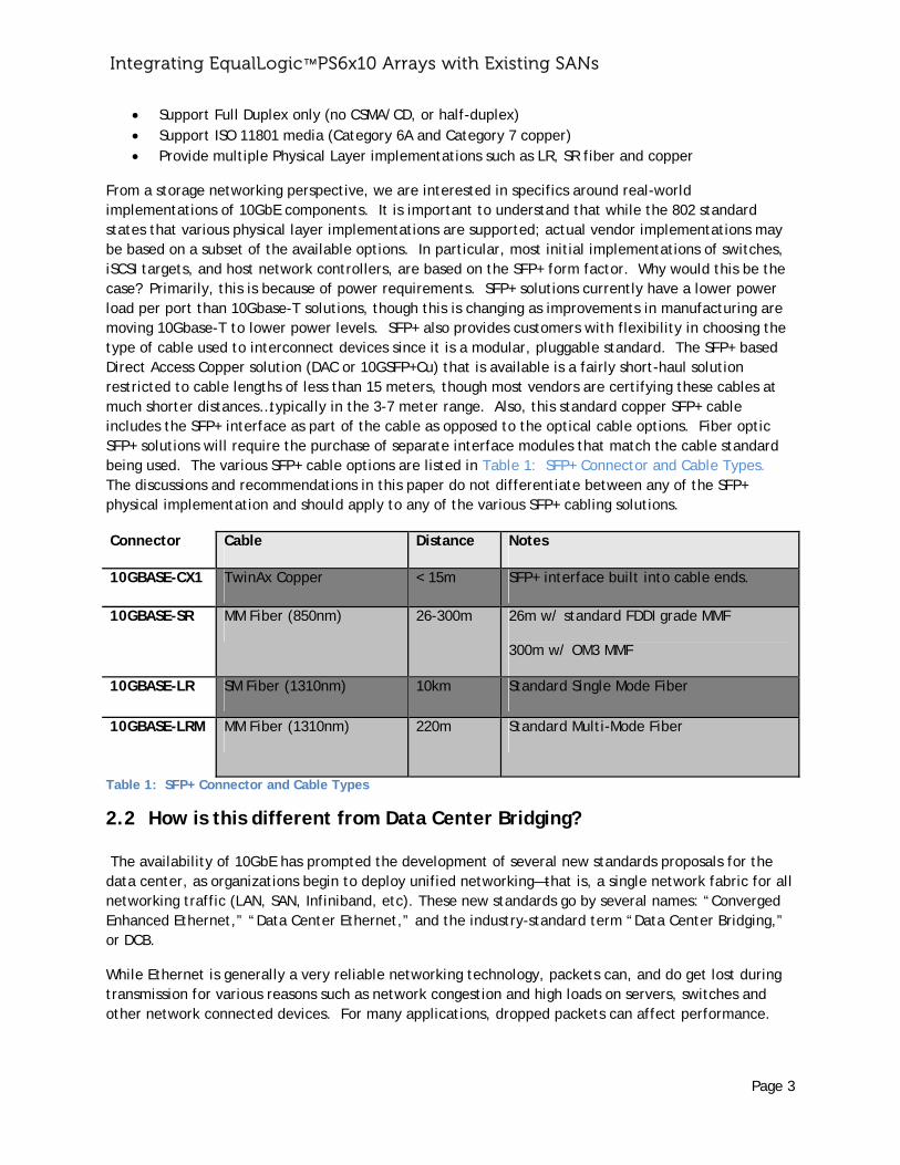
From a storage networking perspective, we are interested in specifics around real-world implementations of 10GbE components. It is important to understand that while the 802 standard states that various physical layer implementations are supported; actual vendor implementations may be based on a subset of the available options. In particular, most initial implementations of switches, iSCSI targets, and host network controllers, are based on the SFP+ form factor. Why would this be the case? Primarily, this is because of power requirements. SFP+ solutions currently have a lower power load per port than 10Gbase-T solutions, though this is changing as improvements in manufacturing are moving 10Gbase-T to lower power levels. SFP+ also provides customers with flexibility in choosing the type of cable used to interconnect devices since it is a modular, pluggable standard. The SFP+ based Direct Access Copper solution (DAC or 10GSFP+Cu) that is available is a fairly short-haul solution restricted to cable lengths of less than 15 meters, though most vendors are certifying these cables at much shorter distances…typically in the 3-7 meter range. Also, this standard copper SFP+ cable includes the SFP+ interface as part of the cable as opposed to the optical cable options. Fiber optic SFP+ solutions will require the purchase of separate interface modules that match the cable standard being used. The various SFP+ cable options are listed in Table 1: SFP+ Connector and Cable Types. The discussions and recommendations in this paper do not differentiate between any of the SFP+ physical implementation and should apply to any of the various SFP+ cabling solutions.
Connector Cable Distance Notes
10GBASE-CX1 TwinAx Copper < 15m SFP+ interface built into cable ends.
10GBASE-SR MM Fiber (850nm) 26-300m 26m w/ standard FDDI grade MMF
300m w/ OM3 MMF
10GBASE-LR SM Fiber (1310nm) 10km Standard Single Mode Fiber
10GBASE-LRM MM Fiber (1310nm) 220m Standard Multi-Mode Fiber
Table 1: SFP+ Connector and Cable Types
2.2 How is this different from Data Center Bridging? The availability of 10GbE has prompted the development of several new standards proposals for the data center, as organizations begin to deploy unified networking—that is, a single network fabric for all networking traffic (LAN, SAN, Infiniband, etc). These new standards go by several names: “Converged Enhanced Ethernet,” “Data Center Ethernet,” and the industry-standard term “Data Center Bridging,” or DCB.
While Ethernet is generally a very reliable networking technology, packets can, and do get lost during transmission for various reasons such as network congestion and high loads on servers, switches and other network connected devices. For many applications, dropped packets can affect performance.
Integra
This is espguarantee
DCB is a sthe Etherprovide a Ethernet Ethernet)the draft everywhe
3 IntNow that EqualLogiconsists oEqualLogi10GbE hoallow you
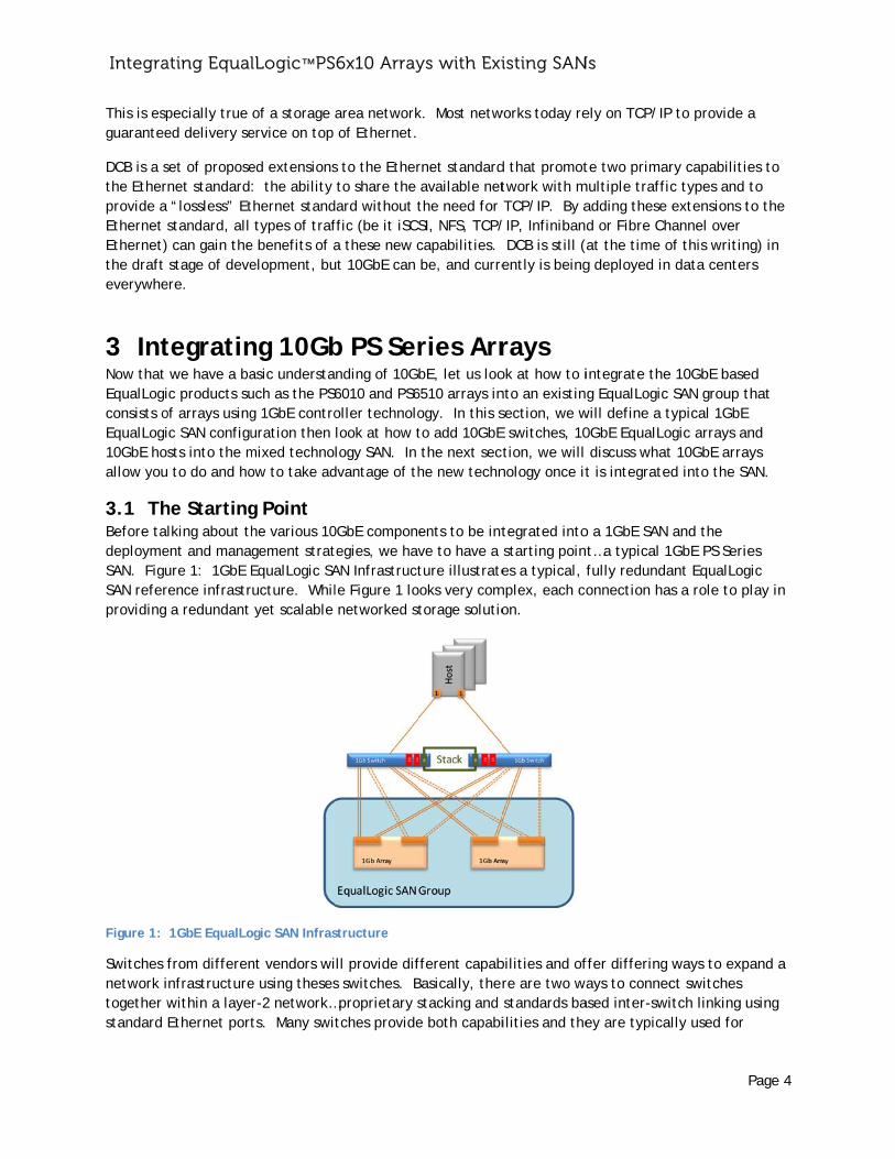
3.1 ThBefore tadeploymeSAN. FiguSAN referproviding
Figure 1:
Switches network itogether wstandard
ating Equal
pecially true ed delivery se
set of proposenet standard “lossless” Etstandard, all can gain the stage of deveere.
tegratin we have a bac products su
of arrays usingc SAN configusts into the m to do and ho
he Startinglking about th
ent and manaure 1: 1GbE Erence infrastr a redundant
1GbE EqualLo
from differennfrastructurewithin a layeEthernet port
lLogic™ PS
of a storage ervice on top
ed extensions: the ability thernet stand types of traf
e benefits of aelopment, bu
ng 10Gbasic understauch as the PS6g 1GbE controuration then mixed technoow to take ad
g Point he various 10gement stratEqualLogic SAructure. Whil yet scalable
ogic SAN Infras
nt vendors wie using thesesr-2 network…ts. Many swi
6x10 Array
area network of Ethernet.
s to the Ether to share the dard without tffic (be it iSCSa these new cut 10GbE can
b PS Sernding of 10G6010 and PS6oller technololook at how tlogy SAN. In
dvantage of th
0GbE componetegies, we havAN Infrastructle Figure 1 lo networked st
structure
ll provide difs switches. B
…proprietary stches provide
ys with Exi
k. Most netw
rnet standard available netthe need for SI, NFS, TCP/capabilities. be, and curre
ries ArrbE, let us loo
6510 arrays inogy. In this sto add 10GbE the next seche new techn
ents to be intve to have a ture illustrate
ooks very comtorage solutio
fferent capabBasically, therstacking and e both capabi
isting SAN
works today re
d that promottwork with m TCP/IP. By a/IP, Infiniban DCB is still (ently is being
rays ok at how to into an existinsection, we wE switches, 10tion, we will
nology once it
tegrated into starting poines a typical,
mplex, each coon.
bilities and ofre are two wa standards bailities and the
Ns
ely on TCP/IP
te two primarmultiple traffiadding these d or Fibre Chat the time og deployed in
integrate theg EqualLogic
will define a t0GbE EqualLo discuss whatt is integrate
o a 1GbE SAN t…a typical 1fully redundaonnection ha
ffer differing ays to connec
ased inter-swiey are typica
P
P to provide a
ry capabilitiec types and t extensions tohannel over of this writing data centers
e 10GbE based SAN group thtypical 1GbE ogic arrays ant 10GbE arrayed into the SA
and the GbE PS Serie
ant EqualLogias a role to pl
ways to expact switches itch linking u
ally used for
Page 4
a
es to to o the
g) in s
d hat
nd ys AN.
es ic ay in
and a
sing
Integrating EqualLogic™ PS6x10 Arrays with Existing SANs
Page 5
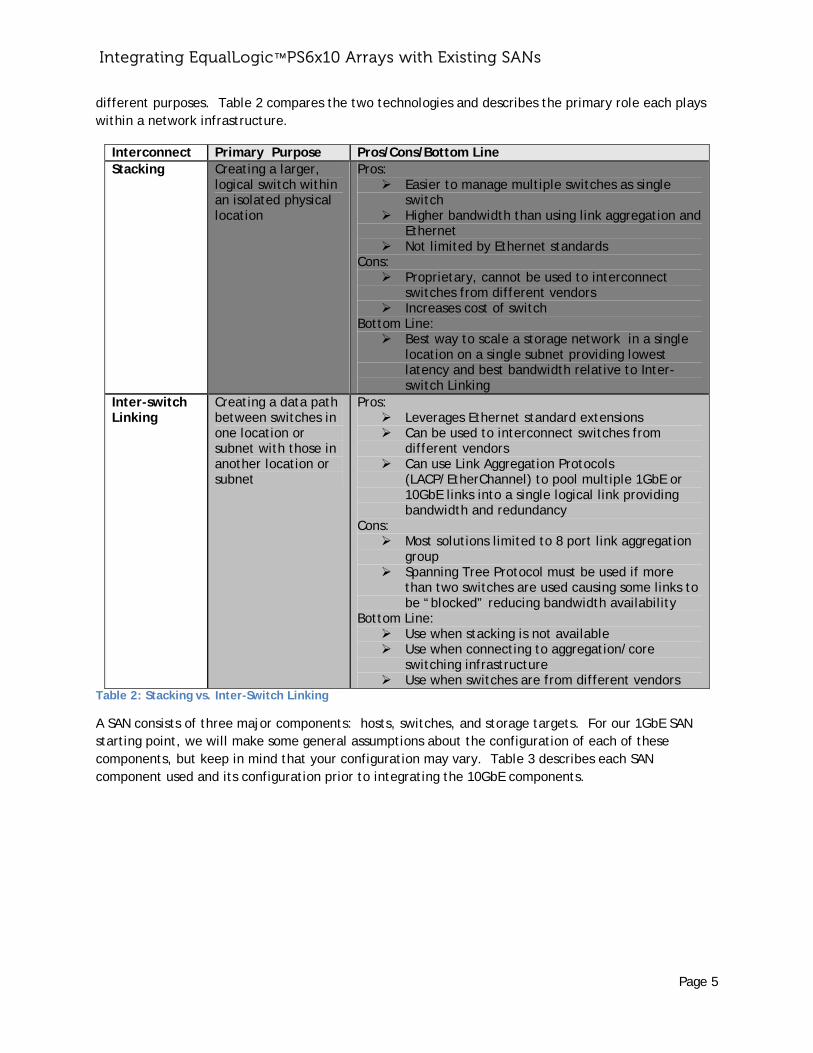
different purposes. Table 2 compares the two technologies and describes the primary role each plays within a network infrastructure.
Interconnect Primary Purpose Pros/Cons/Bottom Line Stacking Creating a larger,
logical switch within an isolated physical location
Pros: Easier to manage multiple switches as single
switch Higher bandwidth than using link aggregation and
Ethernet Not limited by Ethernet standards
Cons: Proprietary, cannot be used to interconnect
switches from different vendors Increases cost of switch
Bottom Line: Best way to scale a storage network in a single
location on a single subnet providing lowest latency and best bandwidth relative to Inter-switch Linking
Inter-switch Linking
Creating a data path between switches in one location or subnet with those in another location or subnet
Pros: Leverages Ethernet standard extensions Can be used to interconnect switches from
different vendors Can use Link Aggregation Protocols
(LACP/EtherChannel) to pool multiple 1GbE or 10GbE links into a single logical link providing bandwidth and redundancy
Cons: Most solutions limited to 8 port link aggregation
group Spanning Tree Protocol must be used if more
than two switches are used causing some links to be “blocked” reducing bandwidth availability
Bottom Line: Use when stacking is not available Use when connecting to aggregation/core
switching infrastructure Use when switches are from different vendors
Table 2: Stacking vs. Inter-Switch Linking
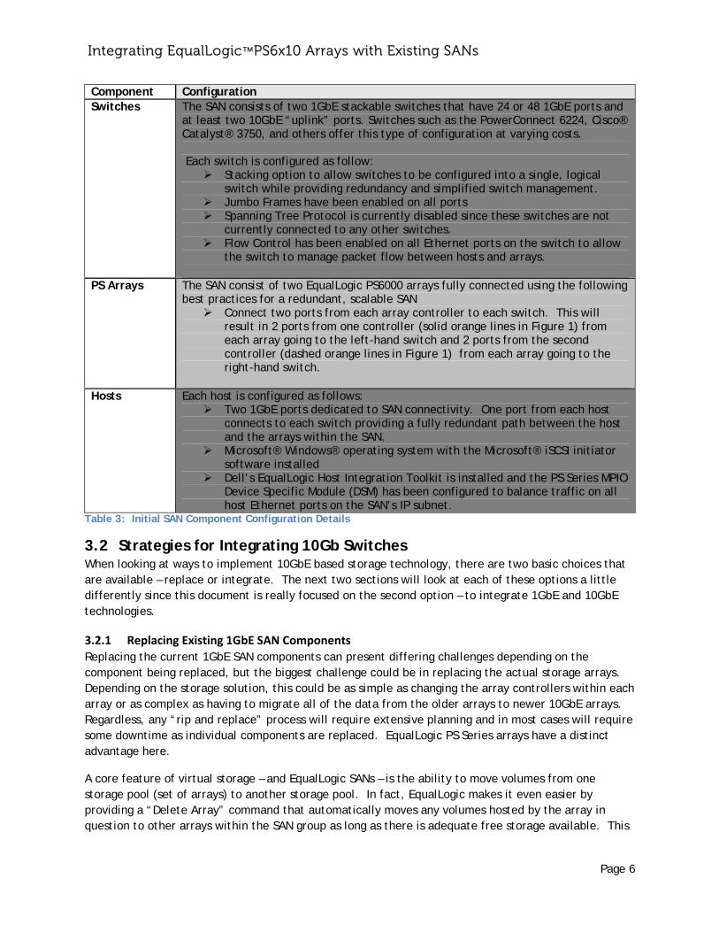
A SAN consists of three major components: hosts, switches, and storage targets. For our 1GbE SAN starting point, we will make some general assumptions about the configuration of each of these components, but keep in mind that your configuration may vary. Table 3 describes each SAN component used and its configuration prior to integrating the 10GbE components.
Integrating EqualLogic™ PS6x10 Arrays with Existing SANs
Page 6
Component Configuration Switches The SAN consists of two 1GbE stackable switches that have 24 or 48 1GbE ports and
at least two 10GbE “uplink” ports. Switches such as the PowerConnect 6224, Cisco® Catalyst® 3750, and others offer this type of configuration at varying costs. Each switch is configured as follow:
Stacking option to allow switches to be configured into a single, logical switch while providing redundancy and simplified switch management.
Jumbo Frames have been enabled on all ports Spanning Tree Protocol is currently disabled since these switches are not
currently connected to any other switches. Flow Control has been enabled on all Ethernet ports on the switch to allow
the switch to manage packet flow between hosts and arrays.
PS Arrays The SAN consist of two EqualLogic PS6000 arrays fully connected using the following best practices for a redundant, scalable SAN
Connect two ports from each array controller to each switch. This will result in 2 ports from one controller (solid orange lines in Figure 1) from each array going to the left-hand switch and 2 ports from the second controller (dashed orange lines in Figure 1) from each array going to the right-hand switch.
Hosts Each host is configured as follows: Two 1GbE ports dedicated to SAN connectivity. One port from each host
connects to each switch providing a fully redundant path between the host and the arrays within the SAN.
Microsoft® Windows® operating system with the Microsoft® iSCSI initiator software installed
Dell’s EqualLogic Host Integration Toolkit is installed and the PS Series MPIO Device Specific Module (DSM) has been configured to balance traffic on all host Ethernet ports on the SAN’s IP subnet.
Table 3: Initial SAN Component Configuration Details
3.2 Strategies for Integrating 10Gb Switches When looking at ways to implement 10GbE based storage technology, there are two basic choices that are available – replace or integrate. The next two sections will look at each of these options a little differently since this document is really focused on the second option – to integrate 1GbE and 10GbE technologies.
3.2.1 Replacing Existing 1GbE SAN Components
Replacing the current 1GbE SAN components can present differing challenges depending on the component being replaced, but the biggest challenge could be in replacing the actual storage arrays. Depending on the storage solution, this could be as simple as changing the array controllers within each array or as complex as having to migrate all of the data from the older arrays to newer 10GbE arrays. Regardless, any “rip and replace” process will require extensive planning and in most cases will require some downtime as individual components are replaced. EqualLogic PS Series arrays have a distinct advantage here.
A core feature of virtual storage – and EqualLogic SANs – is the ability to move volumes from one storage pool (set of arrays) to another storage pool. In fact, EqualLogic makes it even easier by providing a “Delete Array” command that automatically moves any volumes hosted by the array in question to other arrays within the SAN group as long as there is adequate free storage available. This
Integrating EqualLogic™ PS6x10 Arrays with Existing SANs
Page 7
feature, along with the ability to have 1Gb arrays in the same SAN with 10Gb arrays, means that EqualLogic provides a simpler process for migrating to a 10Gb solution than a complete replacement of the entire storage solution that is required with most vendors. Once the data has been migrated, the 1Gb arrays can be removed from the SAN group and repurposed.
While this is a viable option, many customers will want to continue to take advantage of their 1Gb arrays, whether for lower priority data storage, test/dev environments or archival disk-to-disk backup solutions. The primary way to do this is to take advantage of the same capability just mentioned – supporting Groups with both 1Gb and 10Gb arrays – to seamlessly integrate 10Gb arrays into the existing Group and immediately taking advantage of this higher performance storage in parallel with the existing storage.
3.2.2 Integrate 10Gb w/ existing 1Gb
In many customer environments, there will be a need to have 1Gb arrays and 10Gb arrays coexist in the same SAN infrastructure and same EqualLogic SAN group. There are many advantages to this solution. In many cases, only a small number of applications will need the additional performance that a 10Gb array will provide. By integrating 10Gb arrays into the existing SAN group with 1Gb arrays, the administrator will have the flexibility of advanced storage tiering capabilities providing the ability to migrate volumes supporting applications in need of additional performance from existing 1Gb arrays to new, higher-performance 10Gb arrays and allowing the administrator to continue to manage both types of storage arrays within the same SAN group. The next several sections will provide more insight into just how to integrate 10Gb arrays into your existing EqualLogic SAN group.
3.3 Preparing the Network Infrastructure When considering integrating 10Gb networking components into an existing 1Gb SAN infrastructure, planning is one of the most important steps for success. Several considerations must be made when planning this integration including:
How many 10Gb arrays will need to be integrated?
The number of arrays will help determine the number of ports need from the candidate switches. The number of ports required per array will vary by model, but in most cases, at least two 10Gb ports from each array controller for a total of four 10Gb ports per array (2 controllers per array) will need to be connected to the SAN infrastructure to ensure that all arrays and hosts have a redundant path through the SAN infrastructure.
How many 10GbE hosts will be connecting?
Again, this will help determine the number of ports that will be needed in the final solution. Each host will require two 10GbE ports.
Do the existing 1Gb switches have any 10Gb uplink ports and if so, are they SFP+ compatible?
Each switch vendor has many different models of their 1Gb switches. Each model family will have different features depending on the target market. One feature in more robust, higher performance switch families is the integration of several 10GbE ports that can be used as uplink ports to other switches or to support 10Gb edge devices (like a host or array). The number of 10GbE ports available and the socket/cable types supported will vary from vendor to vendor. In many cases, these switches will provide between two and four 10Gb ports. Older switch models may not support SFP+ as a connector type, while newer models may offer SFP+
Integrating EqualLogic™ PS6x10 Arrays with Existing SANs
Page 8
as an option. Since most newer 10GbE switches and EqualLogic arrays use the SFP+ standard for connections, the 1GbE switches currently in use will need to have this option available as well.
If the existing 1Gb switches do not have integrated 10Gb ports, integration of 10Gb will not be possible without replacing the existing 1Gb switches. Options in this scenario include purchasing 10Gb switches that have options to integrate multiple 1Gb ports or that have dual speed sensing ports and optional 1000Base-T SFP+ modules, or looking at 10Gb switches that have a stacking technology that is compatible with existing 1Gb switches. In most cases, the new 10Gb switches will have to be from the same vendor as the existing 1Gb switches.
3.3.1 10Gb Switches
When considering candidate 10Gb switches, it is helpful to understand the options and features that are typically available in the current offerings. As 10Gb standards progress and mature, additional features will be added over time by all of the switch vendors, but initial implementations will have some restrictions. If you compare the past transition from 100 megabit Ethernet to 1GbE, you will see a gradual expansion of new features and technologies that were introduced over time. Initial 1GbE switches, when first introduced, had very limited features and capabilities. Almost all of the switches were non-stacking, layer 2 switches. Many switches at the time did not offer 1GbaseT connections, but used proprietary connections.
The transition to 10GbE switches appears to be following a similar course. 10Gb ports were initially introduced as uplink ports on 1Gb switches and used a variety of non-standard physical connection types such as XFP, XENPAK, and X2. As the 10GbE standard has matured, an industry migration to a more standard SFP+ solution has taken place and over the next several years, the standard will more than likely migrate to a standard 10Gbase-T connection type for copper connections similar to current 1Gbase-T switches today.
Likewise, the set of features on current 10Gb switches is somewhat limited. There are few vendors offering switches in the “edge” switch segment that offer more advanced features such as dedicated stacking functionality, layer 3 routing and larger port counts. To get these features with current offerings will require purchasing more advanced “aggregate” or “core” switches. This will present some challenges when designing larger SANs that require more ports as some of these ports will need to be used to inter-connect switches to each other in a redundant fashion. With these limitations, we need to also look at how these limitations affect the overall SAN design with respect to EqualLogic. The next several sections will discuss the use of Link Aggregation Groups to connect switches together, how Spanning Tree will affect these inter-switch links (ISLs) and how EqualLogic PS Series design also affects ISL and other SAN design requirements.
3.3.1.1 LinkAggregationandInter‐SwitchLinkingSince most 10Gb switches currently do not provide any high bandwidth stacking functionality, these switches will need to be interconnected using the existing 10Gb ports on each switch in conjunction with industry standard link aggregation functionality to combine multiple ports into a single logical connection. This provides a single logical pipe that provides greater than 10 gigabits of bandwidth between switches. To create these link aggregation groups (LAG), switch vendors typically provide support for the link aggregation control protocol (LACP) as defined by IEEE standard 802.3ad (since upgraded to 802.3AX).
Integra
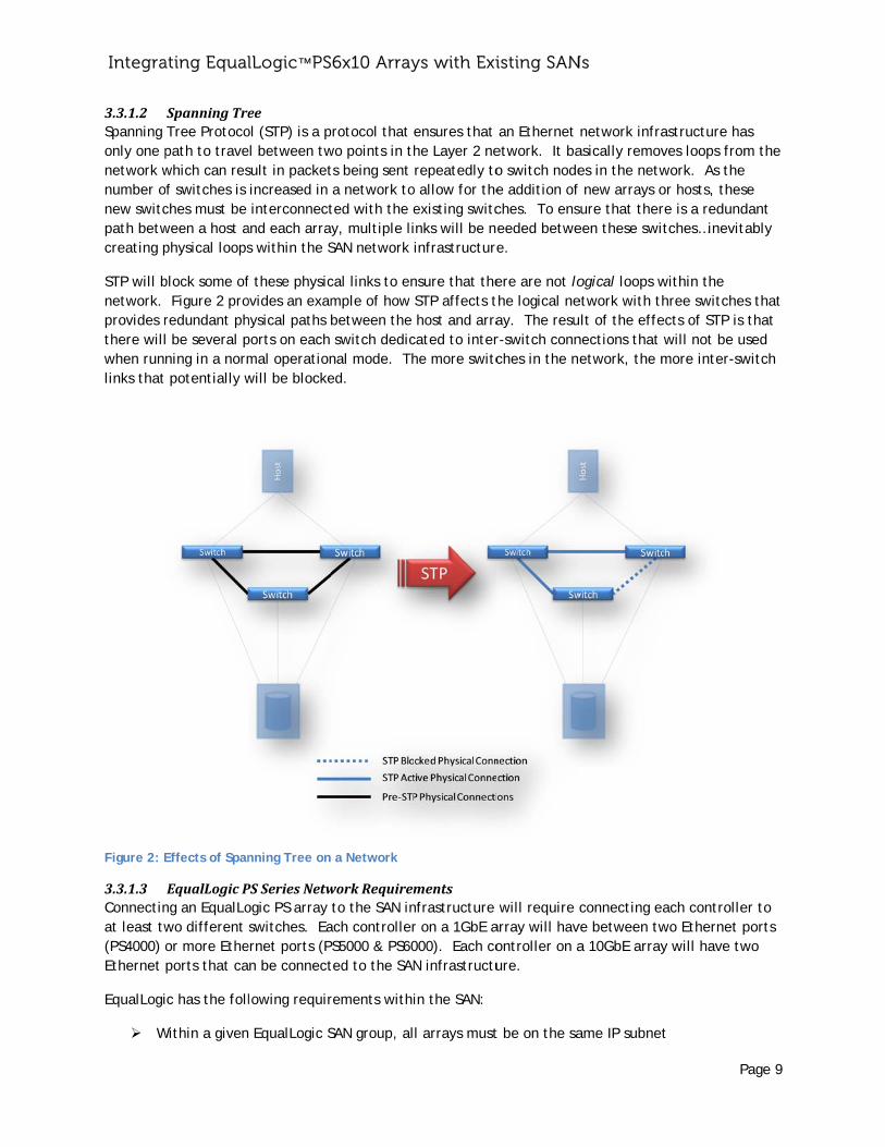
3.3.1.2 Spanning only one pnetwork wnumber onew switcpath betwcreating p
STP will bnetwork. provides rthere willwhen runlinks that
Figure 2: E
3.3.1.3 Connectinat least tw(PS4000) oEthernet
EqualLogi
W
ating Equal
SpanningTre Tree Protocopath to travewhich can resf switches is ches must be ween a host aphysical loops
block some of Figure 2 proredundant phl be several pning in a norm potentially w
Effects of Span
EqualLogicPng an EqualLowo different or more Etheports that ca
c has the foll
Within a given
lLogic™ PS
eeol (STP) is a pel between twsult in packet increased in interconnect
and each arras within the S
f these physicovides an examhysical paths bports on each mal operationwill be blocke
nning Tree on
PSSeriesNetwogic PS array switches. Ea
ernet ports (Pn be connect
lowing requir
EqualLogic S
6x10 Array
protocol that wo points in thts being sent a network toted with the ey, multiple liSAN network
cal links to enmple of how between the switch dedicnal mode. Thed.
a Network
workRequiremto the SAN in
ach controllerS5000 & PS60
ted to the SAN
rements withi
SAN group, al
ys with Exi
ensures that he Layer 2 nerepeatedly to
o allow for theexisting switcinks will be ninfrastructure
nsure that theSTP affects t host and arracated to interhe more switc
mentsnfrastructure r on a 1GbE a000). Each coN infrastructu
in the SAN:
l arrays must
isting SAN
an Ethernet etwork. It bao switch nodee addition of ches. To enseeded betwee.
ere are not lothe logical neay. The resur-switch connches in the ne
will require carray will havontroller on aure.
t be on the sa
Ns
network infraasically removes in the netw new arrays oure that ther
een these swi
ogical loops wetwork with thlt of the effe
nections that etwork, the m
connecting eve between twa 10GbE array
ame IP subnet
P
astructure haves loops fromwork. As theor hosts, thesre is a redundtches…inevit
within the hree switchesects of STP is will not be umore inter-sw
ach controllewo Ethernet py will have tw
t
Page 9
as m the
se dant ably
s that that sed
witch
er to ports wo
Integra
Fo A
Et W
m A
en Ju
ha Po
as
Poei
4 Mix
4.1 TeThe followconsiderePS Series candidate
Each illus
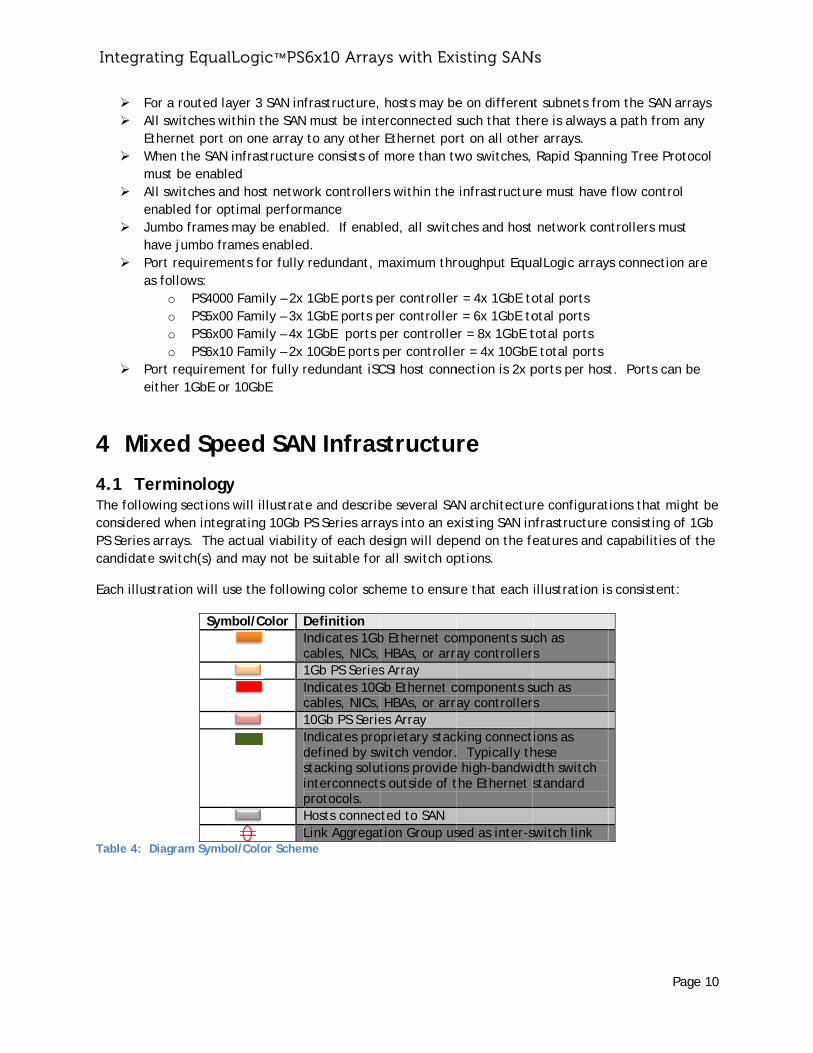
Table 4: D
ating Equal
or a routed lall switches wthernet port
When the SAN must be enablll switches annabled for opumbo frames ave jumbo fraort requiremes follows:
o PS4000o PS5x00o PS6x00o PS6x10
ort requiremeither 1GbE or
xed Spe
erminologywing sectionsed when integ arrays. The e switch(s) an
tration will u
Sym
Diagram Symb
lLogic™ PS
ayer 3 SAN inithin the SANon one array infrastructured nd host netwoptimal perform may be enabames enabledents for fully
0 Family – 2x 0 Family – 3x 0 Family – 4x 0 Family – 2x ent for fully rr 10GbE
eed SAN
y s will illustratgrating 10Gb actual viabili
nd may not be
use the follow
mbol/Color
c
c
dsip
ol/Color Schem
6x10 Array
frastructure,N must be inte to any otherre consists of
ork controllermance bled. If enabd. redundant, m
1GbE ports p 1GbE ports p 1GbE ports 10GbE ports redundant iSC
N Infras
te and describPS Series arraity of each dee suitable for
wing color sch
Definition Indicates 1Gbcables, NICs, 1Gb PS SeriesIndicates 10Gcables, NICs, 10Gb PS SerieIndicates prodefined by swstacking solutinterconnectsprotocols. Hosts connecLink Aggregatme
ys with Exi
hosts may beerconnected r Ethernet por more than tw
rs within the
led, all switc
maximum thr
per controllerper controllerper controlle per controlleCSI host conn
structu
be several SAays into an exesign will depr all switch op
heme to ensur
b Ethernet co HBAs, or arrs Array Gb Ethernet c HBAs, or arres Array prietary stac
witch vendor.tions provides outside of t
cted to SAN tion Group us
isting SAN
e on differensuch that thert on all othewo switches,
infrastructur
ches and host
roughput Equ
r = 4x 1GbE tor = 6x 1GbE toer = 8x 1GbE ter = 4x 10GbEnection is 2x p
re
AN architectuxisting SAN inpend on the fptions.
re that each
omponents suray controller
components sray controller
cking connect. Typically the high-bandwithe Ethernet
sed as inter-s
Ns
nt subnets froere is always er arrays. Rapid Spann
re must have
t network con
alLogic array
otal ports otal ports total ports E total ports ports per hos
re configuratnfrastructure features and c
illustration is
uch as rs
such as rs
tions as hese idth switch standard
switch link
Pa
om the SAN ar a path from a
ing Tree Prot
flow control
ntrollers must
ys connection
t. Ports can
tions that mig consisting ofcapabilities o
s consistent:
age 10
rrays any
tocol
t
are
be
ght be f 1Gb of the
Integrating EqualLogic™ PS6x10 Arrays with Existing SANs
Page 11
4.2 Recommended Connection Strategies
4.2.1 Attaching a single 10GbE Array to Existing 1GbE Modular Switches
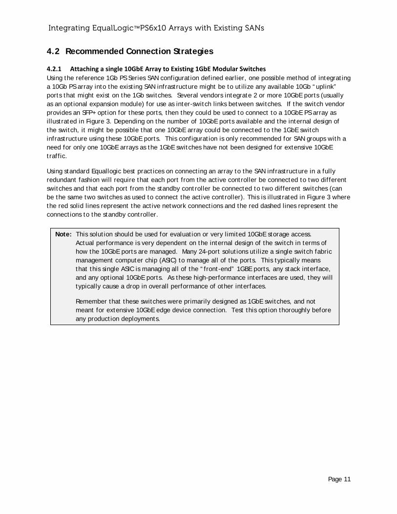
Using the reference 1Gb PS Series SAN configuration defined earlier, one possible method of integrating a 10Gb PS array into the existing SAN infrastructure might be to utilize any available 10Gb “uplink” ports that might exist on the 1Gb switches. Several vendors integrate 2 or more 10GbE ports (usually as an optional expansion module) for use as inter-switch links between switches. If the switch vendor provides an SFP+ option for these ports, then they could be used to connect to a 10GbE PS array as illustrated in Figure 3. Depending on the number of 10GbE ports available and the internal design of the switch, it might be possible that one 10GbE array could be connected to the 1GbE switch infrastructure using these 10GbE ports. This configuration is only recommended for SAN groups with a need for only one 10GbE arrays as the 1GbE switches have not been designed for extensive 10GbE traffic.
Using standard Equallogic best practices on connecting an array to the SAN infrastructure in a fully redundant fashion will require that each port from the active controller be connected to two different switches and that each port from the standby controller be connected to two different switches (can be the same two switches as used to connect the active controller). This is illustrated in Figure 3 where the red solid lines represent the active network connections and the red dashed lines represent the connections to the standby controller.
Note: This solution should be used for evaluation or very limited 10GbE storage access. Actual performance is very dependent on the internal design of the switch in terms of how the 10GbE ports are managed. Many 24-port solutions utilize a single switch fabric management computer chip (ASIC) to manage all of the ports. This typically means that this single ASIC is managing all of the “front-end” 1GBE ports, any stack interface, and any optional 10GbE ports. As these high-performance interfaces are used, they will typically cause a drop in overall performance of other interfaces.
Remember that these switches were primarily designed as 1GbE switches, and not meant for extensive 10GbE edge device connection. Test this option thoroughly before any production deployments.
Integra
Figure 3:
4.2.2 A
When theadd new s10GbE mocenter co10GbE arr
First, doeThese porNetwork Pcontrol, e
Second, alimitationthere is amodule tobetween inhibitor, this overswith lowe
4.2.3 A
If more threcommeability to available
ating Equal
Single 10Gb A
Adding 10GbE
e existing iSCSswitch modulodules to suppre-edge archrays or hosts.
es the switch rts must meetPerformance etc.
and just as imns on the size module thato chassis inteblade module it is importasubscription iser oversubscri
Adding Dedica
han one 10Gbnded that de do this with to provide in
lLogic™ PS
Array Using 10
E Blades to Ex
SI SAN infrastles that proviport higher bitectures, bu There are tw
support all tht the require Guidelines o
mportant, is co of the conne
t has ten 10Gbrface that caes within the nt to understs the lower thiption.
ated 10GbE S
bE arrays or ifdicated 10Gbexisting 1GbE
nter-switch co
6x10 Array
Gb Uplink Por
xisting 1GbE C
ructure conside 10GbE por
bandwidth intt these same
wo important
he standard Ements of a sw
on equallogic.
onsidering ovection betweebE ports (100
an support 50 switch chasstand the amohe overall po
witches to th
f hosts with 1bE switches bE switches wionnections be
ys with Exi
rts on 1Gb Swi
Chassis Switc
ists of scalabrts. Many 1Gerfaces for in
e ports may bet factors to co
Ethernet and witch for use .com). This i
versubscriptioen the blade 0Gb of bandwGb of bandwiis. While thi
ount of oversuotential perfo
he 1GbE Infra
0GbE NICs nee added to thill depend on etween the 1G
isting SAN
itches
ches
le chassis swiGb switch chanterconnectine used for 10onsider with t
iSCSI protoco with EqualLoncludes supp
on. Many cha module and
width within tidth, then ths may or mayubscription wormance of th
astructure
eed to be conhe current 1G these switchGbE and 10G
Ns
itches, it mayassis vendors png switches in0GbE edge cothis solution.
ols on these 1ogic arrays (seport for jumbo
assis switchesthe chassis bhe module), ere is a 2:1 oy not be a pe
within the chahe SAN compa
nnected to thGbE SAN infrahes having 10bE switches.
Pa
y be possibleprovide thesen many data nnections suc
10GbE ports? ee PS Series Ao frames, flow
s can have ackplane. If but only has
oversubscriptirformance
assis. The higared to a swit
he SAN, then iastructure. TGb uplink po Figure 4
age 12
to e
ch as
Array w
a ion
gher tch
it is The rts
Integrating EqualLogic™ PS6x10 Arrays with Existing SANs
Page 13
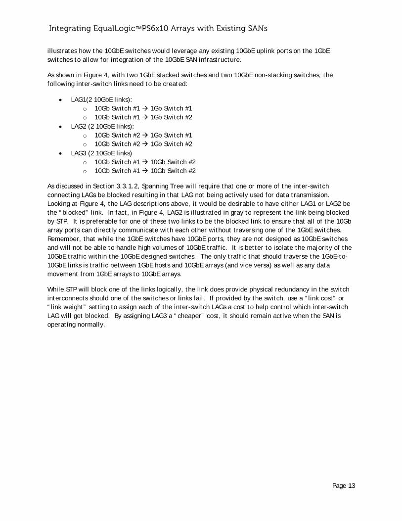
illustrates how the 10GbE switches would leverage any existing 10GbE uplink ports on the 1GbE switches to allow for integration of the 10GbE SAN infrastructure.
As shown in Figure 4, with two 1GbE stacked switches and two 10GbE non-stacking switches, the following inter-switch links need to be created:
LAG1(2 10GbE links): o 10Gb Switch #1 1Gb Switch #1 o 10Gb Switch #1 1Gb Switch #2
LAG2 (2 10GbE links): o 10Gb Switch #2 1Gb Switch #1 o 10Gb Switch #2 1Gb Switch #2
LAG3 (2 10GbE links) o 10Gb Switch #1 10Gb Switch #2 o 10Gb Switch #1 10Gb Switch #2
As discussed in Section 3.3.1.2, Spanning Tree will require that one or more of the inter-switch connecting LAGs be blocked resulting in that LAG not being actively used for data transmission. Looking at Figure 4, the LAG descriptions above, it would be desirable to have either LAG1 or LAG2 be the “blocked” link. In fact, in Figure 4, LAG2 is illustrated in gray to represent the link being blocked by STP. It is preferable for one of these two links to be the blocked link to ensure that all of the 10Gb array ports can directly communicate with each other without traversing one of the 1GbE switches. Remember, that while the 1GbE switches have 10GbE ports, they are not designed as 10GbE switches and will not be able to handle high volumes of 10GbE traffic. It is better to isolate the majority of the 10GbE traffic within the 10GbE designed switches. The only traffic that should traverse the 1GbE-to-10GbE links is traffic between 1GbE hosts and 10GbE arrays (and vice versa) as well as any data movement from 1GbE arrays to 10GbE arrays.
While STP will block one of the links logically, the link does provide physical redundancy in the switch interconnects should one of the switches or links fail. If provided by the switch, use a “link cost” or “link weight” setting to assign each of the inter-switch LAGs a cost to help control which inter-switch LAG will get blocked. By assigning LAG3 a “cheaper” cost, it should remain active when the SAN is operating normally.
Integra
Figure 4:
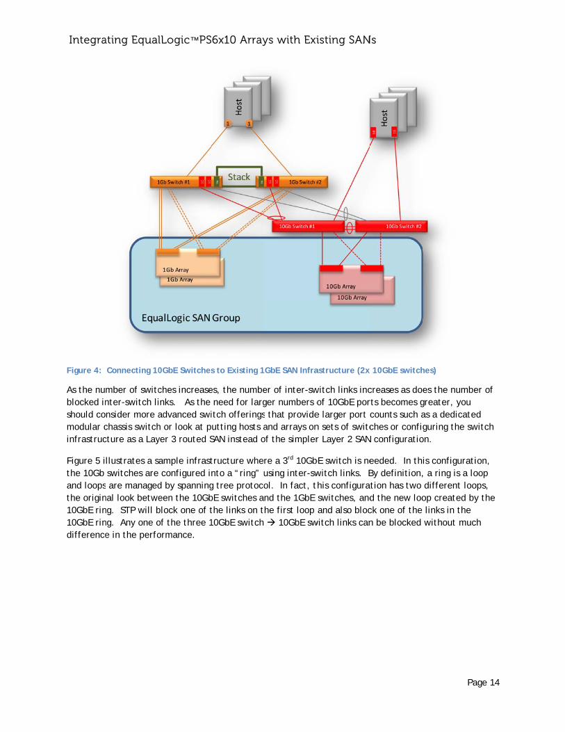
As the nublocked inshould comodular cinfrastruc
Figure 5 ithe 10Gb and loopsthe origin10GbE rin10GbE rindifference
ating Equal
Connecting 10
mber of switcnter-switch linsider more achassis switchcture as a Lay
llustrates a s switches are are managed
nal look betweng. STP will bng. Any one oe in the perfo
lLogic™ PS
0GbE Switches
ches increaseinks. As the advanced swih or look at pyer 3 routed S
ample infrast configured id by spanningeen the 10Gbblock one of tof the three 1ormance.
6x10 Array
s to Existing 1
es, the numbe need for largitch offeringsutting hosts aSAN instead o
tructure whento a “ring” ug tree protocobE switches athe links on t10GbE switch
ys with Exi
GbE SAN Infra
er of inter-swger numbers os that provideand arrays onof the simpler
re a 3rd 10Gbusing inter-swol. In fact, tnd the 1GbE he first loop 10GbE sw
isting SAN
astructure (2x
witch links incof 10GbE pore larger port cn sets of switcr Layer 2 SAN
bE switch is newitch links. Bhis configura switches, and and also bloc
witch links can
Ns
10GbE switch
creases as doerts becomes gcounts such aches or config
N configuratio
eeded. In thBy definition,tion has two d the new loock one of the n be blocked
Pa
hes)
es the numbegreater, you as a dedicateguring the sw
on.
is configurati, a ring is a lo different looop created by links in the without muc
age 14
er of
ed witch
ion, oop ops, y the
ch
Integra
Figure 5: C
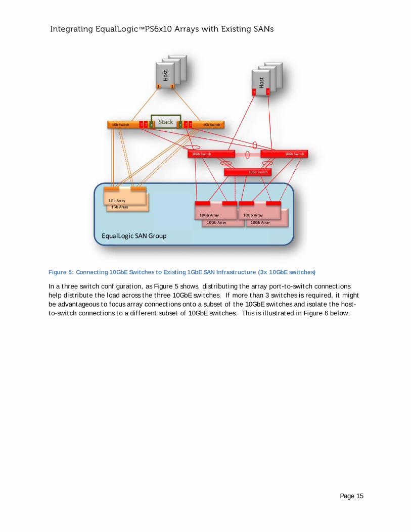
In a threehelp distrbe advantto-switch
ating Equal
Connecting 10
e switch confiribute the loatageous to fo connections
lLogic™ PS
0GbE Switches
iguration, as ad across the cus array con to a differen
6x10 Array
to Existing 1G
Figure 5 show three 10GbE nnections ontnt subset of 10
ys with Exi
GbE SAN Infras
ws, distributin switches. If to a subset of0GbE switche
isting SAN
structure (3x
ng the array more than 3 f the 10GbE swes. This is illu
Ns
10GbE switche
port-to-switc switches is rwitches and iustrated in Fi
Pa
es)
ch connectionrequired, it misolate the hoigure 6 below
age 15
ns might ost-w.
Integra
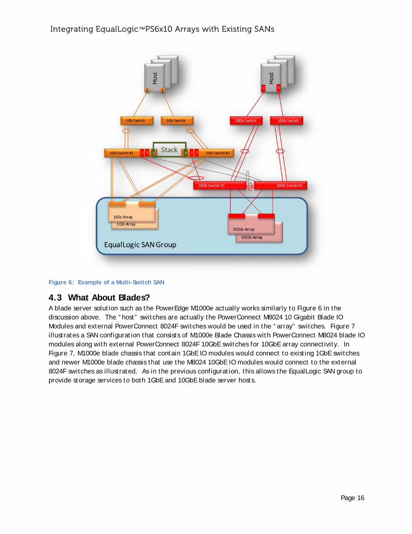
Figure 6:
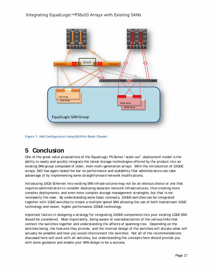
4.3 WhA blade sediscussionModules aillustratesmodules aFigure 7, and newe8024F swiprovide st
ating Equal
Example of a
hat Abouterver solutionn above. Theand external Ps a SAN configalong with ex M1000e bladeer M1000e blaitches as illustorage service
lLogic™ PS
Multi-Switch S
Blades? n such as the e “host” switcPowerConnecguration that
xternal Powere chassis that
ade chassis thstrated. As ines to both 1G
6x10 Array
SAN
PowerEdge Mches are actuct 8024F switct consists of MrConnect 8024t contain 1Gbat use the M8n the previouGbE and 10Gb
ys with Exi
M1000e actuaally the Poweches would b
M1000e Blade4F 10GbE swibE IO modules8024 10GbE IOs configuratio
bE blade serve
isting SAN
ally works simerConnect M8
be used in thee Chassis withitches for 10Gs would connO modules won, this allower hosts.
Ns
milarly to Figu8024 10 Gigabe “array” swith PowerConneGbE array connect to existinwould connectws the EqualL
Pa
ure 6 in the bit Blade IO tches. Figureect M8024 blannectivity. Inng 1GbE switct to the exterLogic SAN grou
age 16
e 7 ade IO n ches rnal up to
Integra
Figure 7: S
5 CoOne of thability to existing Sarrays, Deadvantage
Introducinrequires acomplex dnecessariltogether wtechnolog
Importantshould beconnect tswitches bactually bdiscussed with some
ating Equal
SAN Configura
nclusioe great value easily and quAN group comell has again e of by imple
ng 10Gb Etheadministratordeployments,ly the case. with 1GbE swgy and newer
t factors in dee considered. the switches tbeing, the febe possible an here will woe guidance an
lLogic™ PS
ation Using M1
on e propositionsuickly integramposed of oldraised the bamenting som
rnet into exisrs to consider, and even moBy understan
witches to cre, higher perfo
esigning a str Most importtogether and atures they pnd how you work with all swnd enable you
6x10 Array
000e Blade Ch
s of the Equalate the latestder, even muar on performe straightforw
sting SAN infrr deploying seore complex
nding some baeate a multiplormance 10G
rategy for inttantly, being understandinprovide, and twould interconwitches, but uur SAN design
ys with Exi
hassis
lLogic PS Seri storage techlti-generationance and scaward network
rastructures meparate netwo storage manaasic conceptsle speed SAN bE technolog
egrating 10Gaware of oveng the affectsthe internal dnnect the swiunderstandingn to be a succ
isting SAN
ies “scale outhnologies offen arrays. Witalability that k modificatio
may not be aork infrastrucagement stras, 10GbE switc allowing the
gy.
bE componenersubscriptions of spanningdesign of the itches. Not ag the concepcess.
Ns
t” deploymenered by the pth the introdu administratoons.
n obvious choctures, thus c
ategies, but thches can be i
e use of both
nts into your n of the variog tree. Depen switches wilall of the recopts here shoul
Pa
nt model is thproduct into auction of 10Grs can take
oice or one thcreating morehat is not integrated mainstream 1
existing 1GbEous links that nding on the l dictate whaommendationld provide you
age 17
he an GbE
hat e
1GbE
E SAN
at will ns u