Defining Domain Specific Operational Semantics for ... · PDF fileDefining Domain Specific...
20
Defining Domain Specific Operational Semantics for Activity Diagrams Christoph Knieke, Björn Schindler, Ursula Goltz and Andreas Rausch IfI Technical Report Series IfI-12-04
Transcript of Defining Domain Specific Operational Semantics for ... · PDF fileDefining Domain Specific...
Defining Domain Specific OperationalSemantics for Activity DiagramsChristoph Knieke, Björn Schindler, Ursula Goltz andAndreas Rausch
IfI Technical Report Series IfI-12-04

Impressum
Publisher: Institut für Informatik, Technische Universität ClausthalJulius-Albert Str. 4, 38678 Clausthal-Zellerfeld, Germany
Editor of the series: Jürgen DixTechnical editor: Federico SchlesingerContact: [email protected]
URL: http://www.in.tu-clausthal.de/forschung/technical-reports/
ISSN: 1860-8477
The IfI Review Board
Prof. Dr. Jürgen Dix (Theoretical Computer Science/Computational Intelligence)Prof. i.R. Dr. Klaus Ecker (Applied Computer Science)Prof. Dr. Sven Hartmann (Databases and Information Systems)Prof. i.R. Dr. Gerhard R. Joubert (Practical Computer Science)apl. Prof. Dr. Günter Kemnitz (Hardware and Robotics)Prof. i.R. Dr. Ingbert Kupka (Theoretical Computer Science)Prof. i.R. Dr. Wilfried Lex (Mathematical Foundations of Computer Science)Prof. Dr. Jörg Müller (Business Information Technology)Prof. Dr. Niels Pinkwart (Business Information Technology)Prof. Dr. Andreas Rausch (Software Systems Engineering)apl. Prof. Dr. Matthias Reuter (Modeling and Simulation)Prof. Dr. Harald Richter (Technical Informatics and Computer Systems)Prof. Dr. Gabriel Zachmann (Computer Graphics)Prof. Dr. Christian Siemers (Embedded Systems)PD. Dr. habil. Wojciech Jamroga (Theoretical Computer Science)Dr. Michaela Huhn (Theoretical Foundations of Computer Science)
Defining Domain Specific Operational Semantics forActivity Diagrams
Christoph Knieke, Björn Schindler, Ursula Goltz and Andreas Rausch
C. Knieke, B. Schindler, A. Rausch at Technische Universität Clausthal,Clausthal-Zellerfeld, Germany, (christop.knieke, bjoern.schindler,
andreas.rausch)@tu-clausthal.deU. Goltz at Technische Universität Braunschweig, Braunschweig, Germany,
Abstract
Since the major revision 2 of the Unified Modeling Language (UML), ac-tivity diagrams have acquired many new features, e.g. hierarchy, dataflow and signals. Thus, UML 2 activity diagrams are one of the mostversatile formalisms, and can be applied in different domains. Activitydiagrams are supported by a number of tools enabling for instance theexecution of activity models. Based on the domain these tools have spe-cific requirements and need an adequate interpretation of the informalUML semantics. Wepropose a foundation for a frameworkwhich enablescomposition of operational semantics out of fundamental semantic con-structs. These constructs provide options for domain specific variants.As an example, we introduce two different tool developments based onparticular operational semantics composed by our approach. One toolfocuses on the modeling of information systems whereas the other toolis aimed at the modeling of reactive systems.
1 Introduction
In the recent years, the importance of requirements engineering in largesoftware development projects is increasing significantly. Many approachesfor requirements elicitation and specification of software systems are basedon the development of formal requirements models instead of informal tex-tual descriptions. One of the most common modeling languages support-ing a graphical description of software systems is the UnifiedModeling Lan-guage (UML) [OMG, 2009]. Processes and system behavior are modeled bybehavior diagrams of the UML, e.g. by activity diagrams.
Since the major revision 2 of the UML [OMG, 2009], activity diagramshave acquiredmanynew features, e.g. hierarchy, data flowand signals. Thus,
1
Introduction
UML2 activity diagrams are one of themost versatile formalisms, and can beapplied in different domains, e.g. for the modeling of business processes, al-gorithms, reactive systems, and web applications. In comparison to UML1.x, activity diagrams of version 2 have a token flow semantics based on Petrinets, which is described by informal text.
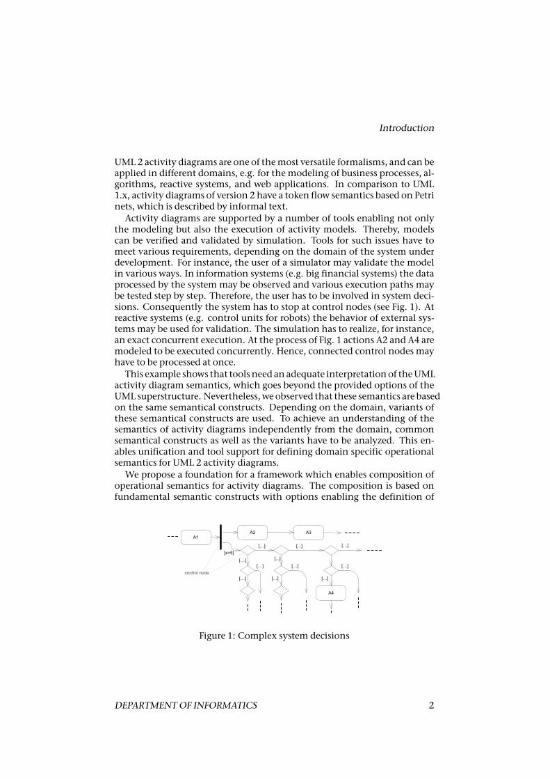
Activity diagrams are supported by a number of tools enabling not onlythe modeling but also the execution of activity models. Thereby, modelscan be verified and validated by simulation. Tools for such issues have tomeet various requirements, depending on the domain of the system underdevelopment. For instance, the user of a simulator may validate the modelin various ways. In information systems (e.g. big financial systems) the dataprocessed by the system may be observed and various execution paths maybe tested step by step. Therefore, the user has to be involved in system deci-sions. Consequently the system has to stop at control nodes (see Fig. 1). Atreactive systems (e.g. control units for robots) the behavior of external sys-tems may be used for validation. The simulation has to realize, for instance,an exact concurrent execution. At the process of Fig. 1 actions A2 and A4 aremodeled to be executed concurrently. Hence, connected control nodes mayhave to be processed at once.
This example shows that tools need an adequate interpretationof theUMLactivity diagram semantics, which goes beyond the provided options of theUML superstructure. Nevertheless, weobserved that these semantics are basedon the same semantical constructs. Depending on the domain, variants ofthese semantical constructs are used. To achieve an understanding of thesemantics of activity diagrams independently from the domain, commonsemantical constructs as well as the variants have to be analyzed. This en-ables unification and tool support for defining domain specific operationalsemantics for UML 2 activity diagrams.
We propose a foundation for a framework which enables composition ofoperational semantics for activity diagrams. The composition is based onfundamental semantic constructs with options enabling the definition of
A2 A3
[x>5]
[…] [...]
[…] [...]
[…] […]
[…] […] […]
[…]
A4
A1
[…]
control node
Figure 1: Complex system decisions
DEPARTMENTOF INFORMATICS 2
OPERATIONAL SEMANTICS FOR ACTIVITY DIAGRAMS
domain specific variants. By our approach, a clear and intuitive operationalsemantics for tool development can be composed which conforms to the in-formal semantics description of the UML.
As an example, we introduce two tool developments based on particularoperational semantics composed in our approach. In both cases, activity di-agrams are considered for the specification of system requirements duringthe early development phase, which is used for validation. The semantics aswell as the tools are well evaluated at research projects and used for realisticsystem developments. The first tool environment focuses on the modelingof information systembehavior [Deynet et al., 2010]whereas the second toolaims at the modeling of reactive system behavior [Knieke and Goltz, 2010].
2 Abstract Syntax of UML 2 Activity Diagrams
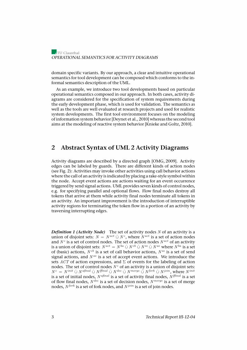
Activity diagrams are described by a directed graph [OMG, 2009]. Activityedges can be labeled by guards. There are different kinds of action nodes(see Fig. 2): Activities may invoke other activities using call behavior actionswhere the call of an activity is indicatedbyplacing a rake-style symbolwithinthe node. Accept event actions are actions waiting for an event occurrencetriggered by send signal actions. UML provides seven kinds of control nodes,e.g. for specifying parallel and optional flows. Flow final nodes destroy alltokens that arrive at them while activity final nodes terminate all tokens inan activity. An important improvement is the introduction of interruptibleactivity regions for terminating the token flow in a portion of an activity bytraversing interrupting edges.
Definition 1 (Activity Node) The set of activity nodes N of an activity is aunion of disjoint sets: N = N act ∪̇ N c, where N act is a set of action nodesand N c is a set of control nodes. The set of action nodes N act of an activityis a union of disjoint sets: N act = N ba ∪̇ N cb ∪̇ N ss ∪̇ N ae where N ba is a setof (basic) actions, N cb is a set of call behavior actions, N ss is a set of sendsignal actions, and N ae is a set of accept event actions. We introduce thesets ACT of action expressions, and Σ of events for the labeling of actionnodes. The set of control nodes N c of an activity is a union of disjoint sets:N c = N init ∪̇ N afinal ∪̇ Nffinal ∪̇ N dec ∪̇ Nmerge ∪̇ N fork ∪̇ N join , where N init
is a set of initial nodes, N afinal is a set of activity final nodes, Nffinal is a setof flow final nodes, N dec is a set of decision nodes, Nmerge is a set of mergenodes,N fork is a set of fork nodes, andN join is a set of join nodes.
3 Technical Report IfI-12-04
Fundamental Semantic Constructs
Definition 2 (Activity) An activity α ∈ A is a tuple1 〈N, E, IAR, source,target, action, guard, event, iar, interr 〉, where N denotes a set of activity nodesand E a set of activity edges. IAR denotes a set of assigned interruptible ac-tivity regions. source : E → N gives the source node of an activity edge,and target : E → N gives the target node of an activity edge. The functionaction : N ba → ACT gives an action expression a ∈ ACT as the labeling of anaction. An activity edgemay have a guard. The guard defines a condition forthe control flow. guard : E ⇀ B gives a boolean expression b ∈ B as the guardon an edge. event : N ss ∪ N ae → Σ is a function for the labeling of a sendsignal action/accept event action by an event σ ∈ Σ. The partial functioniar : N ∪ IAR ⇀ IAR returns for an activity node the interruptible activityregion by which it is directly surrounded. The function iar is also appliedon interruptible activity regions to support the modeling of nested regions.interr : E ⇀ IAR is a partial function, which maps an interrupting edge tothe assigned interruptible activity region. The source node of an interrupt-ing edgemust be in the region that is interrupted by the edge.
Definition 3 (Activity Diagram Specification) An activity diagram specifi-cation AS is defined as a pair: AS = 〈A, p〉 where A is a finite set of activities,and p is a function p : N cb → A from call behavior actions into activities ofA.
1Notational conventions: Symbol → denotes a function, symbol ⇀ denotes a partial func-tion, symbol↔ denotes a bijective function, and⇒ denotes an implication.
Control nodes
Fork node / Join node
Initial node
Activity final node
Flow final node
Decision node / Merge node
Event
Event
(Partition name)
Action
Action nodes
Activity name
Action (with activity partition)
Call behavior action
Send signal action
Accept event action
Activity edges
Activity groups
Interruptible activity region
With guard[result==true]
Interrupting edge
Activity nameActivity
Figure 2: Graphical elements of activity diagrams
DEPARTMENTOF INFORMATICS 4
OPERATIONAL SEMANTICS FOR ACTIVITY DIAGRAMS
3 Fundamental Semantic Constructs
The semantics of activity diagrams is explained in terms of token flow rulesinspired by Petri nets [OMG, 2009]. Tokens of the UML activity specificationare located on elements of the abstract syntax. We use the term location todescribe places where tokens can reside. If a token is placed on a location, itis called active location. Depending on the domain, locationsmay bemappedto different positions.
Definition 4 (Locations) For an activity α, let L be the set of locations in α.The assignment of a location to elements of the abstract syntax is done by adomain-dependent bijective function loc (cf. Section 4).
Definition 5 (Enabled Edge) An activity edge e ∈ E may be enabled, (i.e. ecanbe traversed), if all assigned locations are active (according to the concepttraverse to completion). Depending on the domain, an edgemay be realizedas compound edge. A compound edge consists of a set of edges connected bycontrol nodes.
Definition 6 (Enabled Node) An activity node n ∈ N may be enabled, (i.e.n can be executed), if relevant e ∈ E with n = target(e) are enabled.
3.1 Activity Invocation and Status
UML activities may be invoked by behavioral features (e.g. methods andmessages) or directly by other activities. During execution an activity hasa specific state. This state is defined among others by the active locations.Concurrent execution may lead to multiple activations of a location at thesame time. Thus, we introduce a multisetM of active locations for describ-ing the state of an executed activity.
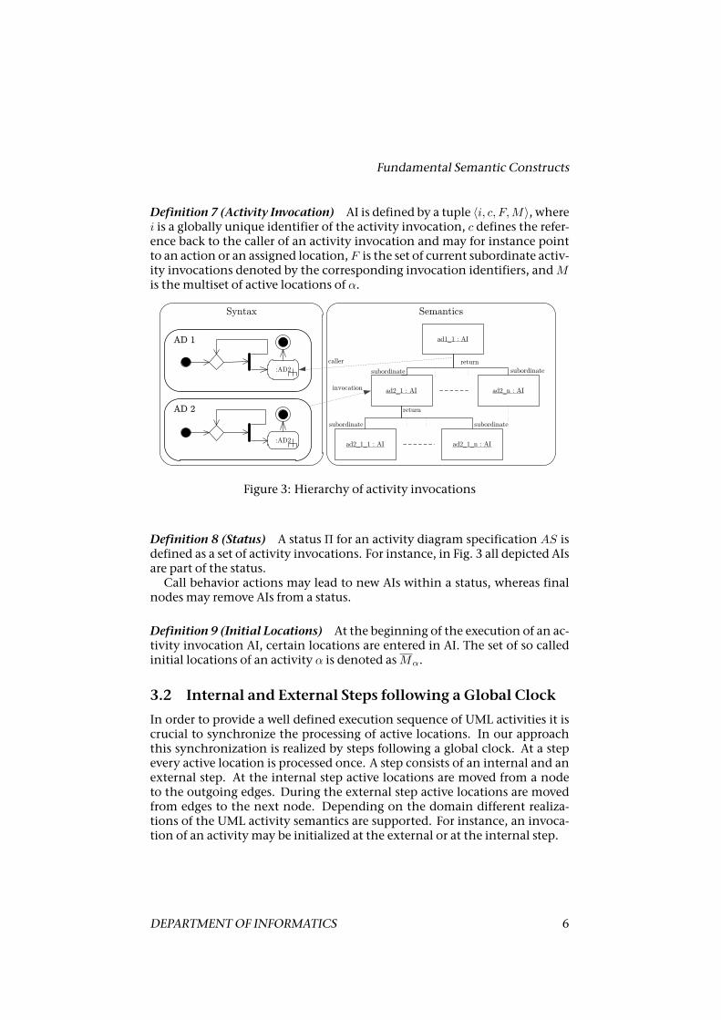
An activitymaybe invokedmore thanonce concurrently. In our approachthe state of invoked activities is described by the term activity invocation (AI).At execution of a call behavior action a subordinate AI is executed. One AImay have more than one subordinate activity invocation. This is the caseat parallel execution. As depicted in Fig. 3 AIs and their relationships forma hierarchy. When the execution of an activity is finished the control flowreturns to the caller.2 An activitymay call itself recursively. At this, activitiesoccur on various layers of the hierarchy. These prerequisites result in thefollowing semantic construct:
2For lack of space, we give a semantics for synchronous call behavior actions only.
5 Technical Report IfI-12-04
Fundamental Semantic Constructs
Definition 7 (Activity Invocation) AI is defined by a tuple 〈i, c, F,M〉, wherei is a globally unique identifier of the activity invocation, c defines the refer-ence back to the caller of an activity invocation and may for instance pointto an action or an assigned location, F is the set of current subordinate activ-ity invocations denoted by the corresponding invocation identifiers, andMis the multiset of active locations of α.
:AD2
Syntax
ad1_1 : AI
ad2_1 : AI ad2_n : AI
:AD2ad2_1_1 : AI ad2_1_n : AI
invocation
return
subordinate subordinate
subordinatesubordinate
return
caller
AD 1
AD 2
Semantics
Figure 3: Hierarchy of activity invocations
Definition 8 (Status) A status Π for an activity diagram specification AS isdefined as a set of activity invocations. For instance, in Fig. 3 all depicted AIsare part of the status.
Call behavior actions may lead to new AIs within a status, whereas finalnodes may remove AIs from a status.
Definition 9 (Initial Locations) At the beginning of the execution of an ac-tivity invocation AI, certain locations are entered in AI. The set of so calledinitial locations of an activity α is denoted asMα.
3.2 Internal and External Steps following a Global Clock
In order to provide a well defined execution sequence of UML activities it iscrucial to synchronize the processing of active locations. In our approachthis synchronization is realized by steps following a global clock. At a stepevery active location is processed once. A step consists of an internal and anexternal step. At the internal step active locations are moved from a nodeto the outgoing edges. During the external step active locations are movedfrom edges to the next node. Depending on the domain different realiza-tions of the UML activity semantics are supported. For instance, an invoca-tion of an activity may be initialized at the external or at the internal step.
DEPARTMENTOF INFORMATICS 6
OPERATIONAL SEMANTICS FOR ACTIVITY DIAGRAMS
3.3 Step Algorithm
The execution of an activity model is described by a step algorithm. A stepis divided into two phases: Leaving nodes (internal step) and traversing en-abled edges (external step). The main realization of the global clock withan external and internal step is described by algorithm 1. The order of theinternal and external step is undeterminded.
Algorithm 1Global clock with an external and internal step phase1: while TRUE do2: Step preparation3: Compute the contents of the internal step4: Execute the internal step5: Compute the contents of the external step6: Execute the external step7: endwhile
3.4 Interruptible Activity Regions
An important concept of UML activities supported by our approach is theconcept of interruptible activity regions (IAR). At the interruption of an IARby an interrupting edge, all included active locations are removed from themultiset M of the associated activity invocation. Additionally all subordi-nate activity invocations invoked by an included call behavior action are re-moved from the status. IARs are allowed to be nested and several interrupt-ing edges may be passed concurrently. In this case it is crucial to prioritizethe handling of interrupting edges. In our approach this is done by theirnesting. Inner IARs have less priority.
Algorithm 2 describes the computation of the external step. The compu-tation is defined by the handling of enabled interrupting edges.
Algorithm 2Compute the contents of the external step1: Compute themultisetEE of enabled edges2: Compute themultiset IE of enabled interrupting edges3: Remove all enabled interrupting edges, for which enabled interrupting edges
with a higher priority exist, from IE4: if IE is not empty then5: IE constitutes the step6: else ifEE is not empty then7: EE constitutes the step8: else9: external step is empty10: end if
7 Technical Report IfI-12-04
Domain Specific Semantics
The realization of the step preparation and execution depends on the se-mantic options assigned to locations, activity invocations and the domainspecific definition of the external and internal step.
4 Domain Specific Semantics
4.1 Operational Semantics for Specifying Information Sys-tems
At the validation of activity models for information systems the user of thesimulator may want to be involved at system decisions. To enable a track-ing of the current decision locations have to be mapped to control nodes.The following semantic options of the fundamental semantic constructs de-scribed in Section3define the operational semantics for the information sys-tem domain:
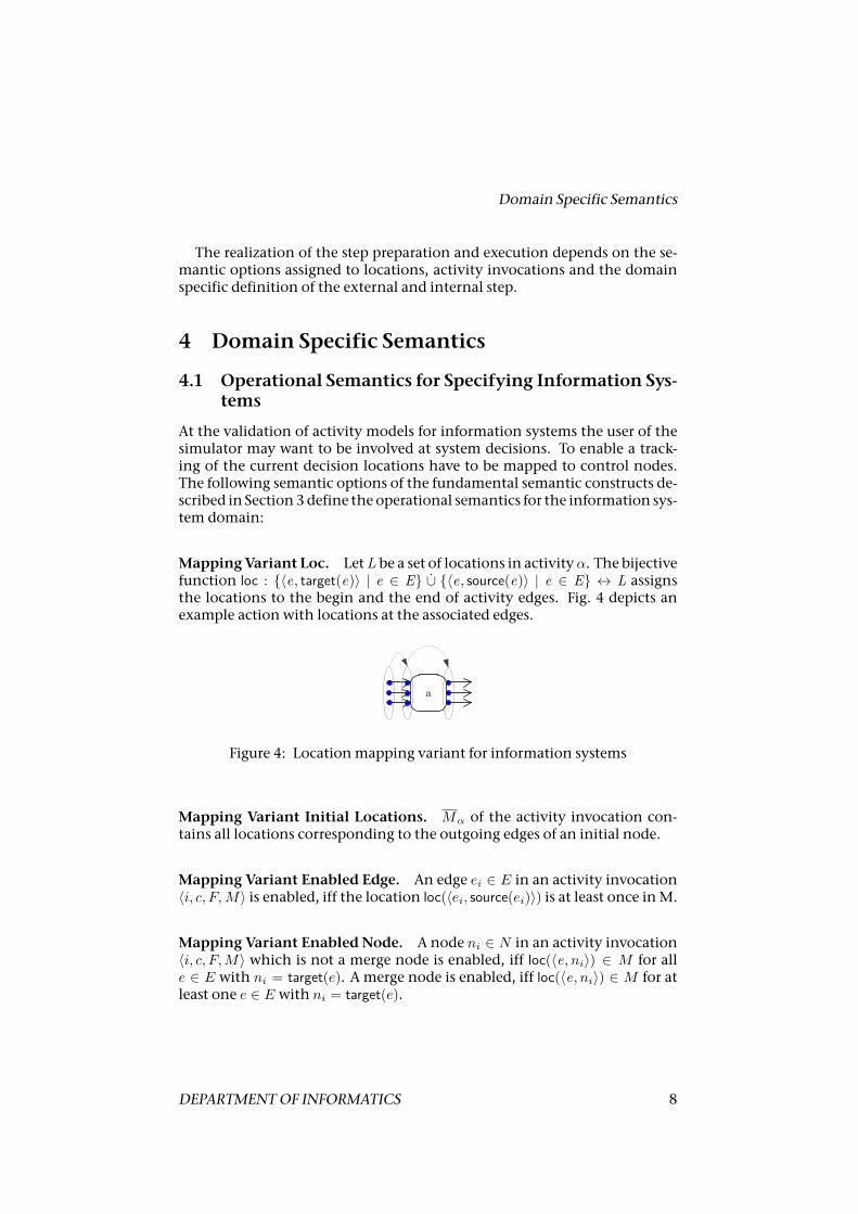
MappingVariant Loc. LetL be a set of locations in activityα. The bijectivefunction loc : {〈e, target(e)〉 | e ∈ E} ∪̇ {〈e, source(e)〉 | e ∈ E} ↔ L assignsthe locations to the begin and the end of activity edges. Fig. 4 depicts anexample action with locations at the associated edges.
a
Figure 4: Locationmapping variant for information systems
Mapping Variant Initial Locations. Mα of the activity invocation con-tains all locations corresponding to the outgoing edges of an initial node.
Mapping Variant Enabled Edge. An edge ei ∈ E in an activity invocation〈i, c, F, M〉 is enabled, iff the location loc(〈ei, source(ei)〉) is at least once inM.
Mapping Variant Enabled Node. A node ni ∈ N in an activity invocation〈i, c, F,M〉 which is not a merge node is enabled, iff loc(〈e, ni〉) ∈ M for alle ∈ E with ni = target(e). A merge node is enabled, iff loc(〈e, ni〉) ∈ M for atleast one e ∈ E with ni = target(e).
DEPARTMENTOF INFORMATICS 8
OPERATIONAL SEMANTICS FOR ACTIVITY DIAGRAMS
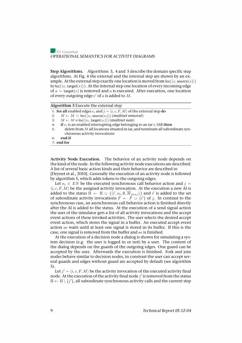
StepAlgorithms. Algorithms 3, 4 and 5 describe the domain specific stepalgorithms. At Fig. 4 the external and the internal step are shown by an ex-ample. At the external step exactly one location ismoved from loc(〈e, source(e)〉)to loc(〈e, target(e)〉). At the internal step one location of every incoming edgeof a = target(e) is removed and a is executed. After execution, one locationof every outgoing edge e′ of a is added toM .
Algorithm 3 Execute the external step1: for all enabled edges ei and j = 〈i, c, F,M〉 of the external step do2: M ←M loc(〈ei, source(ei)〉) (multiset removal )3: M ←M ] loc(〈ei, target(ei)〉) (multiset sum)4: if ei is an enabled interrupting edge belonging to an iar ∈ IAR then5: delete fromM all locations situated in iar, and terminate all subordinate syn-
chronous activity invocations6: end if7: end for
Activity Node Execution. The behavior of an activity node depends onthe kindof thenode. In the following activity node executions are described:A list of several basic action kinds and their behavior are described in[Deynet et al., 2010]. Generally the execution of an activity node is followedby algorithm 5, which adds tokens to the outgoing edges.
Let ni ∈ EN be the executed synchronous call behavior action and j =〈i, c, F,M〉 be the assigned activity invocation. At the execution a new AI isadded to the status Π ← Π ∪ {〈i′, ni, ∅,M p(ni )〉} and i′ is added to the setof subordinate activity invocations F ← F ∪ {i′} of j. In contrast to thesynchronous case, an asynchronous call behavior action is finished directlyafter the AI is added to the status. At the execution of a send signal actionthe user of the simulator gets a list of all activity invocations and the acceptevent actions of these invoked activities. The user selects the desired acceptevent action, which stores the signal in a buffer. An executed accept eventaction ae waits until at least one signal is stored in its buffer. If this is thecase, one signal is removed from the buffer and ae is finished.
At the execution of a decision node a dialog is shown for simulating a sys-tem decision (e.g. the user is logged in or not) by a user. The content ofthe dialog depends on the guards of the outgoing edges. One guard can beaccepted by the user. Afterwards the execution is finished. Fork and joinnodes behave similar to decision nodes, in constrast the user can accept sev-eral guards and edges without guard are accepted by default (see algorithm5).
Let j′ = 〈i, c, F,M〉 be the activity invocation of the executed activity finalnode. At the execution of the activity final node j′ is removed from the statusΠ← Π \ {j′}, all subordinate synchronous activity calls and the current step
9 Technical Report IfI-12-04
Domain Specific Semantics
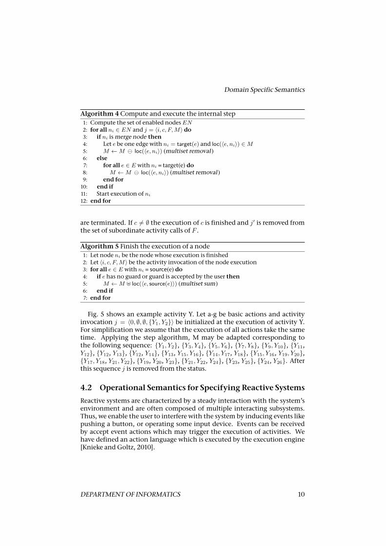
Algorithm 4Compute and execute the internal step1: Compute the set of enabled nodesEN2: for all ni ∈ EN and j = 〈i, c, F,M〉 do3: if ni ismerge node then4: Let e be one edge with ni = target(e) and loc(〈e, ni〉) ∈M5: M ←M loc(〈e, ni〉) (multiset removal )6: else7: for all e ∈ E with ni = target(e) do8: M ←M loc(〈e, ni〉) (multiset removal )9: end for10: end if11: Start execution of ni
12: end for
are terminated. If c 6= ∅ the execution of c is finished and j′ is removed fromthe set of subordinate activity calls of F .
Algorithm 5 Finish the execution of a node1: Let node ni be the node whose execution is finished2: Let 〈i, c, F,M〉 be the activity invocation of the node execution3: for all e ∈ E with ni = source(e) do4: if e has no guard or guard is accepted by the user then5: M ←M ] loc(〈e, source(e)〉) (multiset sum)6: end if7: end for
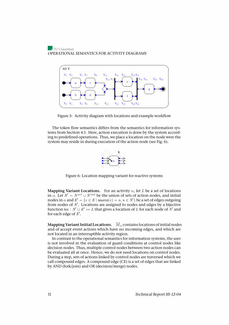
Fig. 5 shows an example activity Y. Let a-g be basic actions and activityinvocation j = 〈0, ∅, ∅, {Y1, Y2}〉 be initialized at the execution of activity Y.For simplification we assume that the execution of all actions take the sametime. Applying the step algorithm, M may be adapted corresponding tothe following sequence: {Y1, Y2}, {Y3, Y4}, {Y5, Y6}, {Y7, Y8}, {Y9, Y10}, {Y11,Y12}, {Y12, Y13}, {Y12, Y14}, {Y13, Y15, Y16}, {Y14, Y17, Y18}, {Y15, Y16, Y19, Y20},{Y17, Y18, Y21, Y22}, {Y19, Y20, Y23}, {Y21, Y22, Y24}, {Y23, Y25}, {Y24, Y26}. Afterthis sequence j is removed from the status.
4.2 Operational Semantics for Specifying Reactive Systems
Reactive systems are characterized by a steady interaction with the system’senvironment and are often composed of multiple interacting subsystems.Thus, we enable the user to interfere with the system by inducing events likepushing a button, or operating some input device. Events can be receivedby accept event actions which may trigger the execution of activities. Wehave defined an action language which is executed by the execution engine[Knieke and Goltz, 2010].
DEPARTMENTOF INFORMATICS 10
OPERATIONAL SEMANTICS FOR ACTIVITY DIAGRAMS
a c e
f
g
AD Y
Y1 Y3 Y9
Y8 Y12
Y14
Y16Y10
Y7 Y11
Y13
Y15
b d
Y6Y2 Y4
Y5 Y17
Y18
Y19
Y20
Y21
Y23
Y22
Y24 Y25 Y26
Figure 5: Activity diagramwith locations and example workflow
The token flow semantics differs from the semantics for information sys-tems from Section 4.1. Here, action execution is done by the system accord-ing to predefined operations. Thus, we place a location on the nodewere thesystemmay reside in during execution of the action node (see Fig. 6).
a
Figure 6: Locationmapping variant for reactive systems
Mapping Variant Locations. For an activity α, let L be a set of locationsin α. Let N′ = N act ∪ N init be the union of sets of action nodes, and initialnodes in α and E′ = {e ∈ E | source(e) = n,n ∈ N′} be a set of edges outgoingfrom nodes of N′. Locations are assigned to nodes and edges by a bijectivefunction loc : N′ ∪ E′ ↔ L that gives a location of L for each node of N′ andfor each edge of E′.
MappingVariant Initial Locations. Mα contains locations of initial nodesand of accept event actions which have no incoming edges, and which arenot located in an interruptible activity region.
In contrast to the operational semantics for information systems, the useris not involved in the evaluation of guard conditions at control nodes likedecision nodes. Thus, multiple control nodes between two action nodes canbe evaluated all at once. Hence, we do not need locations on control nodes.During a step, sets of actions linked by control nodes are traversed which wecall compound edges. A compound edge (CE) is a set of edges that are linkedby AND (fork/join) and OR (decision/merge) nodes.
11 Technical Report IfI-12-04
Domain Specific Semantics
• If an edge in a compound edge enters or leaves an AND node, then ev-ery edge that leaves or enters the AND node is part of the compoundedge.
• If an edge in a compound edge enters (leaves) an OR node, then thereis exactly one edge in the compound edge that leaves (enters) the ORnode.
Mapping Variant Enabled Edge. Let AS be an activity diagram specifica-tion and Π a status ofAS. A CE in an activity invocation 〈i, c, F,M〉 (denotedby cei) is enabled, iff its locations are at least once inM and the guard is eval-uated to TRUE.
The set of locations associated with the edges of ce is denoted by •ce andce• denotes the set of locations entered after ce has been traversed.
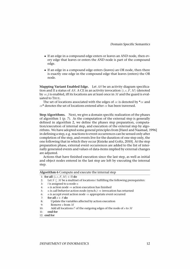
Step Algorithms. Next, we give a domain specific realization of the phasesof algorithm 1 (p. 7). As the computation of the external step is generallydefined in algorithm 2, we define the phases step preparation, computa-tion/execution of internal step, and execution of the external step by algo-rithms. Wehave adopted somegeneral principles from [Harel and Naamad, 1996]in defining a step, e.g. reactions to event occurrences canbe sensed only aftercompletion of the step, and events live for the duration of one step only, theone following that in which they occur [Knieke and Goltz, 2010]. At the steppreparation phase, external event occurrences are added to the list of inter-nally generated events and values of data-items implied by external changesare adjusted.
Actions that have finished execution since the last step, as well as initialand object nodes entered in the last step are left by executing the internalstep.
Algorithm 6Compute and execute the internal step1: for all 〈i, c, F,M〉 ∈ Π do2: Let S ⊆M be amultiset of locations l fulfilling the following prerequisites:3: l is assigned to a node n4: n is action node⇒ action execution has finished5: n is call behavior action node (synch.) ⇒ invocation has returned6: n is accept event action node⇒ appropriate event occurred7: for all s ∈ S do8: Update the variables affected by action execution9: Remove s fromM10: Add all locations l′ of the outgoing edges of the node of s toM11: end for12: end for
DEPARTMENTOF INFORMATICS 12
OPERATIONAL SEMANTICS FOR ACTIVITY DIAGRAMS
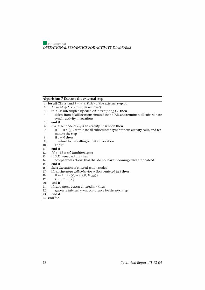
Algorithm 7 Execute the external step1: for allCEs cei and j = 〈i, c, F,M〉 of the external step do2: M ←M •cei (multiset removal )3: if IAR is interrupted by enabled interrupting CE then4: delete fromM all locations situated in the IAR, and terminate all subordinate
synch. activity invocations5: end if6: if a target node of cei is an activity final node then7: Π ← Π \ {j}, terminate all subordinate synchronous activity calls, and ter-
minate the step8: if c 6= ∅ then9: return to the calling activity invocation10: end if11: end if12: M ←M ] ce•i (multiset sum)13: if IAR is enabled in j then14: accept event actions that that do not have incoming edges are enabled15: end if16: Start execution of entered action nodes17: if synchronous call behavior action t entered in j then18: Π← Π ∪ {〈i′, loc(t), ∅,M p(t)〉}19: F ← F ∪ {i′}20: end if21: if send signal action entered in j then22: generate internal event occurrence for the next step23: end if24: end for
13 Technical Report IfI-12-04
RelatedWork
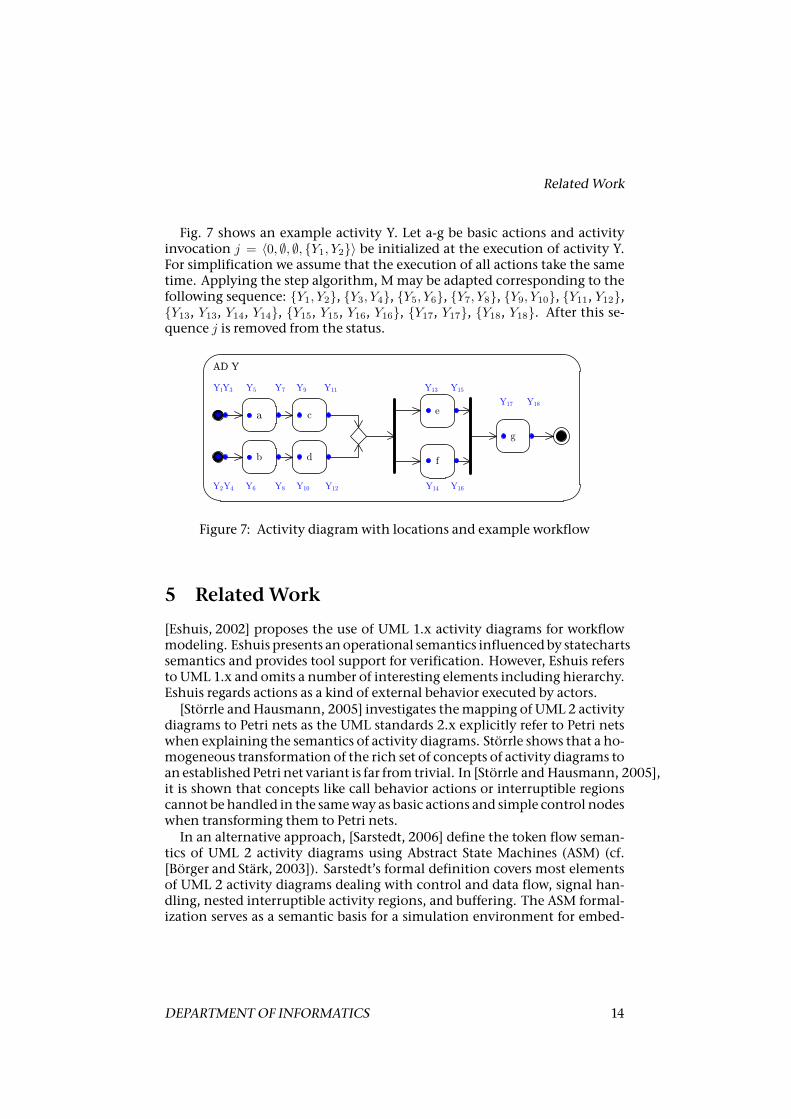
Fig. 7 shows an example activity Y. Let a-g be basic actions and activityinvocation j = 〈0, ∅, ∅, {Y1, Y2}〉 be initialized at the execution of activity Y.For simplification we assume that the execution of all actions take the sametime. Applying the step algorithm, Mmay be adapted corresponding to thefollowing sequence: {Y1, Y2}, {Y3, Y4}, {Y5, Y6}, {Y7, Y8}, {Y9, Y10}, {Y11, Y12},{Y13, Y13, Y14, Y14}, {Y15, Y15, Y16, Y16}, {Y17, Y17}, {Y18, Y18}. After this se-quence j is removed from the status.
a c e
f
g
AD Y
Y1Y3 Y9
Y8 Y10
Y7 Y11
b d
Y6Y2Y4
Y5 Y13
Y14
Y15
Y16
Y17 Y18
Y12
Figure 7: Activity diagramwith locations and example workflow
5 RelatedWork
[Eshuis, 2002] proposes the use of UML 1.x activity diagrams for workflowmodeling. Eshuis presents anoperational semantics influencedby statechartssemantics and provides tool support for verification. However, Eshuis refersto UML 1.x and omits a number of interesting elements including hierarchy.Eshuis regards actions as a kind of external behavior executed by actors.
[Störrle and Hausmann, 2005] investigates themapping of UML 2 activitydiagrams to Petri nets as the UML standards 2.x explicitly refer to Petri netswhen explaining the semantics of activity diagrams. Störrle shows that a ho-mogeneous transformation of the rich set of concepts of activity diagrams toan establishedPetri net variant is far from trivial. In [Störrle and Hausmann, 2005],it is shown that concepts like call behavior actions or interruptible regionscannot be handled in the sameway as basic actions and simple control nodeswhen transforming them to Petri nets.
In an alternative approach, [Sarstedt, 2006] define the token flow seman-tics of UML 2 activity diagrams using Abstract State Machines (ASM) (cf.[Börger and Stärk, 2003]). Sarstedt’s formal definition covers most elementsof UML 2 activity diagrams dealing with control and data flow, signal han-dling, nested interruptible activity regions, and buffering. The ASM formal-ization serves as a semantic basis for a simulation environment for embed-
DEPARTMENTOF INFORMATICS 14
OPERATIONAL SEMANTICS FOR ACTIVITY DIAGRAMS
ded system design: [Sarstedt, 2006]models the structure of embedded appli-cations by UML 2 class diagrams. The behavior of a class is specified in anassociated ActiveChart.
[Engels et al., 2007, Engels et al., 2009] use dynamicmetamodeling to de-scribe the behavioral semantics of UML activity diagrams. Dynamic metamodeling extends the metamodel defining the syntax of a modeling no-tation [Soltenborn and Engels, 2009]. The extended metamodel – the so-called runtime metamodel – provides concepts for describing states (configu-rations) of an executedmodel: The configurations are described by themod-els itself extended by information on the currently active elements. Thegraph transformation rules specify how to transit to the next configurationby modifying instances of the runtime metamodel. Thus, the graph trans-formation rules correspond to the step algorithm defined in the previoussection.
In [Staines, 2010] a formal mapping from activity diagrams to Petri netsbased on Triple Graph Grammar (TGG) rules is defined as an extension ofStörrles approach. Unlike Störrles simple mapping, TGG rules constitute amodel-to-model transformation. In addition, the transformation is executableand allows for the construction of complex rules for supporting semanticallyintricate constructs. [Staines, 2010] define the mapping for simple place/transition nets. For applying the TGG approach to the complete language el-ements of activity diagrams, additional classes of Petri nets have to be takeninto account. However, it is still an open question, whether a unique classof Petri nets exists that can serve as a foundation for the transformation sup-porting all elements of UML 2 activity diagrams and for which analysis toolsare available.
[Grönniger et al., 2010] define a formal semantics for a subset of activitydiagrams which allows for a domain-specific interpretation of activity di-agrams: variants determine which system entities make up a diagram in-stance. They focus on rather low-level interpretations of activity diagramsas simple action or method executions. Advanced constructs like interrupt-ible activity regions are currently not supported. The semantics is encodedin a theorem prover as a basis for verification [Grönniger et al., 2010, p. 5].In contrast, our algorithmic definitions of the semantics aim at tool devel-opment for fully executable models. [Grönniger et al., 2010] do not handleconflicts/interferences whichmay arise if multiple instances of activities areexecuted concurrently [Grönniger et al., 2010, p. 8]. Furthermore, their vari-ation points concerning the token flow semantics are not able to support theconcept of compound edges w.r.t. complex concatenations of control nodes(e.g. decision and fork) which will not be traversed instantaneously accord-ing to [Grönniger et al., 2010].
Finally, wemention approaches defining a composable semantics formodel-based notations (e.g. [Niu et al., 2002]). In [Esmaeilsabzali and Day, 2010]a formal framework to define the semantics of Big-Step Modelling Languages
15 Technical Report IfI-12-04
References
(BSMLs) is described. A BSML is a language in which a model can respondto an input of the environment via a sequence of small steps, each of whichmay consist of the concurrent execution of a set of transitions[Esmaeilsabzali and Day, 2010]. The semantics ofmany BSMLs can be decon-structed into eight high-level semantic aspects and their semantic options.As an example, a set of semantic options of the STATEMATE-semantics of stat-echarts is given [Esmaeilsabzali and Day, 2010]. The semantic framework forderiving a formal semantics of a BSML defined in[Esmaeilsabzali and Day, 2010] contains a set of parameters. By adjusting theseparameters, an executable BSML-semantics can be derived.
6 Conclusion
In this paper, we analyzed common semantical constructs and possible op-tions for the definition of operational semantics for activity diagrams. Atthis, we introduced a foundation for a framework, which uses these funda-mental semantic constructs for the composition of operational semantics.The provided options of these contructs go beyond the capabilities of theUML superstructure. Two examples demonstrate the applicability of the ap-proach. For the information system domain locations at control nodes en-able an involvement of the user in system decisions. The semantics for thereactive systems domain enable, for instance, an exact concurrent executionby the definition of compound edges. Both semantics supports new UML2.0 features like hierarchy and signals. This paper focuses on control flowof activity diagrams. As a future work common semantic constructs for thedescription of data flow will be considered in detail.
References
[Börger and Stärk, 2003] Börger, E. and Stärk, R. (2003). Abstract State Ma-chines: AMethod for High-Level SystemDesign and Analysis. Springer-Verlag.
[Deynet et al., 2010] Deynet, M., Niebuhr, S., Rausch, A., and Schindler, B.(2010). Enhancing Validation with Prototypes out of Requirements Mod-els. In 21st Australian Software Engineering Conference (ASWEC2010 IndustryTrack).
[Engels et al., 2009] Engels, G., Fisseler, D., and Soltenborn, C. (2009). Im-proving Reusability of Dynamic Meta Modeling Specifications with RuleOverriding. In Proc. of IEEE Symposium on Visual Languages and Human-Centric Computing, VL/HCC 2009, pages 39–46.
DEPARTMENTOF INFORMATICS 16
OPERATIONAL SEMANTICS FOR ACTIVITY DIAGRAMS
[Engels et al., 2007] Engels, G., Soltenborn, C., and Wehrheim, H. (2007).Analysis of UML Activities Using Dynamic Meta Modeling. In Proc. ofthe 9th IFIP WG 6.1 Intern. Conf. on Formal Methods for Open Object-BasedDistributed Systems (FMOODS 2007), volume 4468 of LNCS, pages 76–90.Springer-Verlag.
[Eshuis, 2002] Eshuis, H. (2002). Semantics and Verification of UML ActivityDiagrams forWorkflowModelling. PhD thesis, CTIT, University of Twente.
[Esmaeilsabzali and Day, 2010] Esmaeilsabzali, S. and Day, N. A. (2010). Pre-scriptive Semantics for Big-Step Modelling Languages. In Proc. of the 13thIntern. Conf. on Fundamental Approaches to Software Engineering (FASE 2010),volume 6013 of LNCS, pages 158–172. Springer-Verlag.
[Grönniger et al., 2010] Grönniger, H., Reiss, D., and Rumpe, B. (2010). To-wards a Semantics of Activity Diagrams with Semantic Variation Points.In Petriu, D. C., Rouquette, N., and Haugen, Ø., editors, MODELS 2010,volume 6394 of LNCS, pages 331–345. Springer.
[Harel and Naamad, 1996] Harel, D. and Naamad, A. (1996). The STATEM-ATE Semantics of Statecharts. ACM Transactions on Software Engineeringand Methodologies, 5(4):293–333.
[Knieke and Goltz, 2010] Knieke, C. and Goltz, U. (2010). An Executable Se-mantics forUML2ActivityDiagrams. In ECOOP2010Workshop Proc. of theIntern. Workshop on Formalization of Modeling Languages (FML 2010), pages11–15. ACM Press.
[Niu et al., 2002] Niu, J., Atlee, J. M., and Day, N. A. (2002). ComposableSemantics for Model-based Notations. SIGSOFT Softw. Eng. Notes, 27:149–158.
[OMG, 2009] OMG (2009). UML, Version 2.2. OMG Specification Super-structure and Infrastructure, http://www.omg.org.
[Sarstedt, 2006] Sarstedt, S. (2006). Semantic Foundation and Tool Support forModel-Driven Development with UML 2 Activity Diagrams. PhD thesis, Uni-versität Ulm.
[Soltenborn and Engels, 2009] Soltenborn, C. and Engels, G. (2009). To-wards Test-Driven Semantics Specification. In Proc. of the 12th Intern. Conf.onModelDriven Engineering Languages and Systems (MODELS 2009), volume5795 of LNCS, pages 378–392. Springer-Verlag.
[Staines, 2010] Staines, A. (2010). A TripleGraphGrammarMapping ofUML2 Activities into Petri Nets. International Journal of Computers, 4(1):27–35.
17 Technical Report IfI-12-04

References
[Störrle and Hausmann, 2005] Störrle, H. and Hausmann, J. H. (2005). To-wards a Formal Semantics of UML 2.0 Activities. In Software Eng. 2005,Fachtagung des GI-Fachbereichs Softwaretechnik, volume 64 of LNI, pages117–128. Springer-Verlag.
DEPARTMENTOF INFORMATICS 18