Feature Diagrams: A Survey and a Formal Semantics
10
Feature Diagrams: A Survey and a Formal Semantics Pierre-Yves Schobbens, Patrick Heymans, Jean-Christophe Trigaux University of Namur, Computer Science Department 5000 Namur, Belgium fps,phe,jtrg@infofundp. ac.be Yves Bontemps SMALS MvM/ eGOV 1050 Brussels, Belgium Yves. [email protected] Abstract Feature Diagrams (FD) are a family of popular mod- elling languages used for engineering requirements in sof- ware product lines. FD were first introduced by Kang as part of the FODA (Feature Oriented Domain Analysis) method back in 1990. Since then, various extensions of FODA FD were devised to compensate for a purported am- biguity and lack of precision and expressiveness. Howevel; they never received a proper formal semantics, which is the hallmark of precision and unambiguity as well as a prereq- uisitefor eflcient and safe tool automation. In this paper, we first survey FD variants. Subsequently, we generalize the various syntaxes through a generic con- struction called Free Feature Diagrams (FFD). Formal se- mantics is defined at the FFD level, which provides unam- biguous definition for all the surveyed FD variants in one shot. All formalization choices found a clear answer in the original FODA FD definition, which proved that although informal and scattered throughout many pages, it suffered no ambiguity problem. Our dejinition has several additional advantages: it is formal, concise and generic. We thus argue that it con- tributes to improve the definition, understanding, compar- ison and reliable implementation of FD languages. 1. Introduction Software Product Line (PL) engineering is "a paradigm to develop software applications (software-intensive sys- tems and software products) using platforms and mass cus- tomisation" [17]. Central to the PL paradigm is the mod- elling and management of variability, i.e. the commonali- ties and dlferences in the applications in terms of require- ments, architecture, components, and test artefacts [17]. At all those levels, but especially at the requirement level, vari- ability is commonly modelled through Feature Diagrams (FD). In the last 15 years or so, research and industry have de- veloped several FD languages. The first and seminal pro- posal was introduced as part of the FODA method back in 1990 [12]. An example of a FODA FD is given in Fig. 1. It is inspired from a case study defined in [4] and indicates the allowed combinations of features for a family of sys- tems intended to monitor the engine of a car. As is illus- trated, FODA features are nodes of a graph represented by strings and related by various types of edges. On top of the figure, the feature Monitor Engine System is called the rootfeature, or concept. The edges are used to progressively decompose it into more detailed features. In FODA, there are and- and xor- decompositions (where edges are linked by a line segment, as between Measures and its sons in Fig. 1). The exact meaning of these and other constructs will be discussed extensively throughout the paper. In the sequel, we will refer to FODA FD as Original Feature Trees or OFT for short. "Tree" is because in OFT, FD are structured as trees vs. single-rooted directed acyclic graphs (DAG) as in FORM [13]. Since Kang et ale's initial proposal, several extensions of OFT have been devised as part of the following meth- ods: FORM [ 131, FeatureRSEB [ 101, Generative Program- ming [7], PLUSS [8], and in the work of the following authors: Riebisch et al. [19, 181, van Gurp et al. [24], van Deursen et al. [23], Czarnecki et al. [S, 61, Batory [I] and Benavides et al. [2]. While few authors have recently started to better define their semantics [23, 6, 1, 21, most proponents of FD [13, 10, 7, 19, 18, 24, 81 have not. Still, most of them have argued for an "improved expressive- ness". However, without a formal semantics, they have 14th IEEE International Requirements Engineering Conference (RE'06) 0-7695-2555-5/06 $20.00 © 2006
-
Upload
truongxuyen -
Category
Documents
-
view
220 -
download
1
Transcript of Feature Diagrams: A Survey and a Formal Semantics

Feature Diagrams: A Survey and a Formal Semantics
Pierre-Yves Schobbens, Patrick Heymans, Jean-Christophe Trigaux University of Namur, Computer Science Department
5000 Namur, Belgium fps,phe,jtrg@infofundp. ac. be
Yves Bontemps SMALS MvM/ eGOV
1050 Brussels, Belgium Yves. Bontemps@smnls-mvm. be
Abstract
Feature Diagrams (FD) are a family of popular mod- elling languages used for engineering requirements in sof- ware product lines. FD were first introduced by Kang as part of the FODA (Feature Oriented Domain Analysis) method back in 1990. Since then, various extensions of FODA FD were devised to compensate for a purported am- biguity and lack of precision and expressiveness. Howevel; they never received a proper formal semantics, which is the hallmark of precision and unambiguity as well as a prereq- uisite for eflcient and safe tool automation.
In this paper, we first survey FD variants. Subsequently, we generalize the various syntaxes through a generic con- struction called Free Feature Diagrams (FFD). Formal se- mantics is defined at the FFD level, which provides unam- biguous definition for all the surveyed FD variants in one shot. All formalization choices found a clear answer in the original FODA FD definition, which proved that although informal and scattered throughout many pages, it suffered no ambiguity problem.
Our dejinition has several additional advantages: it is formal, concise and generic. We thus argue that it con- tributes to improve the definition, understanding, compar- ison and reliable implementation of FD languages.
1. Introduction
Software Product Line (PL) engineering is "a paradigm to develop software applications (software-intensive sys- tems and software products) using platforms and mass cus- tomisation" [17]. Central to the PL paradigm is the mod- elling and management of variability, i.e. the commonali- ties and dlferences in the applications in terms of require-
ments, architecture, components, and test artefacts [17]. At all those levels, but especially at the requirement level, vari- ability is commonly modelled through Feature Diagrams (FD).
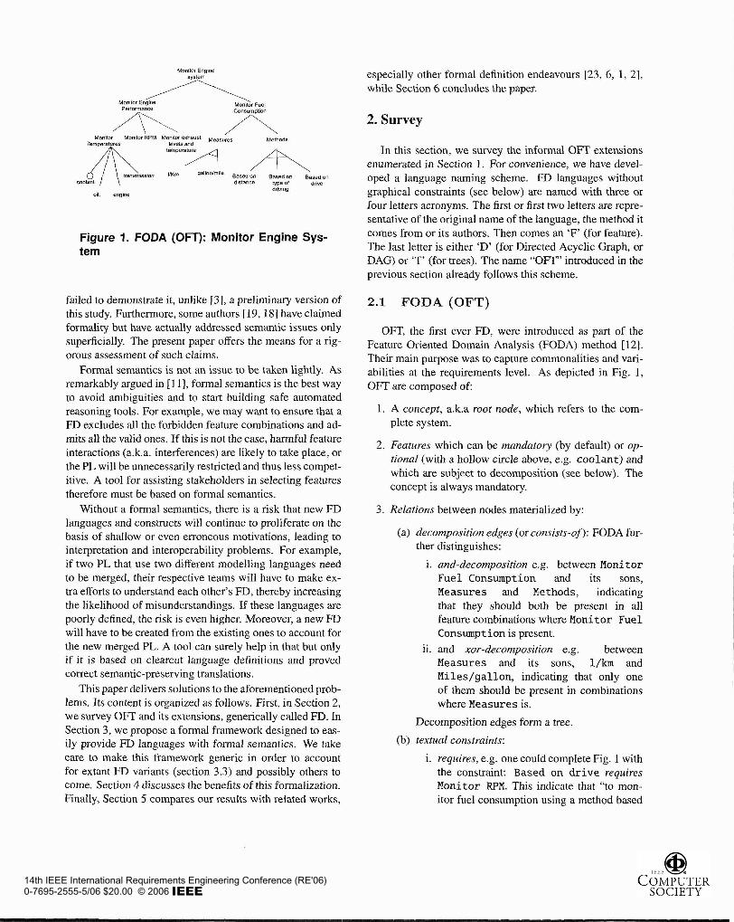
In the last 15 years or so, research and industry have de- veloped several FD languages. The first and seminal pro- posal was introduced as part of the FODA method back in 1990 [12]. An example of a FODA FD is given in Fig. 1. It is inspired from a case study defined in [4] and indicates the allowed combinations of features for a family of sys- tems intended to monitor the engine of a car. As is illus- trated, FODA features are nodes of a graph represented by strings and related by various types of edges. On top of the figure, the feature Monitor Engine System is called the root feature, or concept. The edges are used to progressively decompose it into more detailed features. In FODA, there are and- and xor- decompositions (where edges are linked by a line segment, as between Measures and its sons in Fig. 1). The exact meaning of these and other constructs will be discussed extensively throughout the paper.
In the sequel, we will refer to FODA FD as Original Feature Trees or OFT for short. "Tree" is because in OFT, FD are structured as trees vs. single-rooted directed acyclic graphs (DAG) as in FORM [13].
Since Kang et ale's initial proposal, several extensions of OFT have been devised as part of the following meth- ods: FORM [ 131, FeatureRSEB [ 101, Generative Program- ming [7], PLUSS [8], and in the work of the following authors: Riebisch et al. [19, 181, van Gurp et al. [24], van Deursen et al. [23], Czarnecki et al. [S, 61, Batory [I] and Benavides et al. [2]. While few authors have recently started to better define their semantics [23, 6, 1, 21, most proponents of FD [13, 10, 7, 19, 18, 24, 81 have not. Still, most of them have argued for an "improved expressive- ness". However, without a formal semantics, they have
14th IEEE International Requirements Engineering Conference (RE'06)0-7695-2555-5/06 $20.00 © 2006
Mnnttor Engine system
Petiormanca Monitor Fuel Consumplion
Monitor Monitor RPM Monitor exhaust Measures Temperatures Wvds and
Memods
Based on dbsiance type of
oil. engtne drnrlng
\ Based on
drive
Figure 1. FODA (On): Monltor Engine Sys- tem
failed to demonstrate it, unlike 131, a preliminary version of this study. Furthermore, some authors [19,18] have claimed formality but have actually addressed semantic issues only superficially. The present paper offers the means for a rig- orous assessment of such claims.
Formal semantics is not an issue to be taken lightly. As remarkably argued in [I I], formal semantics is the best way to avoid ambiguities and to start building safe automated reasoning tools. For example, we may want to ensure that a FD excludes all the forbidden feature combinations and ad- mits all the valid ones. If this is not the case, harmful feature interactions (a.k.a. interferences) are likely to take place, or the PL will be unnecessarily restricted and thus less compet- itive. A tool for assisting stakeholders in selecting features therefore must be based on formal semantics.
Without a formal semantics, there is a risk that new FD languages and constructs will continue to proliferate on the basis of shallow or even erroneous motivations, leading to interpretation and interoperability problems. For example, if two PL that use two different modelling languages need to be merged, their respective teams will have to make ex- tra efforts to understand each other's FD, thereby increasing the likelihood of misunderstandings. If these languages are poorly defined, the risk is even higher. Moreover, a new FD will have to be created from the existing ones to account for the new merged PL. A tool can surely help in that but only if it is based on clearcut language definitions and proved correct semantic-preserving translations.
This paper delivers solutions to the aforementioned prob- lems. Its content is organized as follows. First, in Section 2, we survey OFT and its extensions, generically called FD. In Section 3, we propose a formal framework designed to eas- ily provide FD languages with formal semantics. We take care to make this framework generic in order to account for extant FD variants (section 3.3) and possibly others to come. Section 4 discusses the benefits of this formalization. Finally, Section 5 compares our results with related works,
especially other formal definition endeavours [23, 6, 1, 21, while Section 6 concludes the paper.
2. Survey
In this section, we survey the informal OFT extensions enumerated in Section I . For convenience, we have devel- oped a language naming scheme. FD languages without graphical constraints (see below) are named with three or four letters acronyms. The first or first two letters are repre- sentative of the original name of the language, the method it comes from or its authors. Then comes an 'F' (for feature). The last letter is either 'D' (for Directed Acyclic Graph, or DAG) or 'T' (for trees). The name "OFT" introduced in the previous section already follows this scheme.
2.1 FODA (OFT)
OM: the first ever FD, were introduced as part of the Feature Oriented Domain Analysis (FODA) method [12]. Their main purpose was to capture commonalities and vari- abilities at the requirements level. As depicted in Fig. 1, OFT are composed of:
1. A concept, a.k.a root node, which refers to the com- plete system.
2. Features which can be mandatoly (by default) or op- tional (with a hollow circle above, e.g. coolant) and which are subject to decomposition (see below). The concept is always mandatory.
3. Relations between nodes materialized by:
(a) decomposition edges (or consists-of): FODA fur- ther distinguishes:
i. and-decomposition e.g. between Monitor Fuel Consumption and its sons, Measures and Methods, indicating that they should both be present in all feature combinations where Monitor Fuel Consumption is present.
ii. and xor-decomposition e.g. between Measures and its sons, I/km and Miles/gallon, indicating that only one of them should be present in combinations where Measures is.
Decomposition edges form a tree.
(b) textual constraints:
i. requires, e.g. one could complete Fig. 1 with the constraint: Based on d r i v e requires Monitor RPM. This indicate that "to mon- itor fuel consumption using a method based
14th IEEE International Requirements Engineering Conference (RE'06)0-7695-2555-5/06 $20.00 © 2006

on drive, we need to monitor the engine's RPM". Thus, the former feature cannot be present if the latter is not.
ii. mutex, an abbreviation for "mutually exclu- sive with", indicates that two features cannot be present simultaneously.
2.2 FORM (OFD)
Kang et al. have proposed the Feature-Oriented Reuse Method (FORM) [13] as an extension of FODA. Their main motivation was to enlarge the scope of feature modelling. They argue that feature modelling is not only relevant for requirements engineering but also for software design. In terms of FD, several changes occurred:
1. FD are not necessarily trees but can be DAG.
2. Each feature pertains to one of four layers: the ca- pability layer, the operating environment layer, the domain technology layer or the implementation tech- nique layer.
3. In addition to the composed-of relationship (equiva- lent to consists-of in OFT), two types of graphical re- lationships were added: generalization,fspecializa~ion and implemented-by.
4. Feature names appear in boxes.
We call the abstract syntax of such diagrams "Original Feature Diagrams" (OFD).
In this paper, we only consider the constructs which have an influence on the feature combinations allowed in the fi- nal products (see Def. 3.5). Therefore, only the first change (trees becomes DAG) is relevant for us. In our running ex- ample, the FD is a tree, so the FORM version of it is similar to Fig. 1, except that features would be boxed.
2.3 FeatuRSEB (RFD)
The FeatuRSEB method [lo] is a combination of FODA and the Reuse-Driven Software Engineering Busi- ness (RSEB) method. RSEB is a use-case driven systematic reuse process, where variability is captured by structuring use cases and object models with variation points and vari- ants. FeatuRSEB FD have the following characteristics:
1. They are DAG.
2. Decomposition operator or (black diamond) is added to xor (white diamond) and and. Features which sons are decomposed through or or xor are called variation points and those sons are called variants.
3. They possess a graphical representation (dashed ar- rows) for the constraints requires and mutex.
We call such diagrams "RSEB Feature Diagrams" (RFD). An example is given in Fig. 2.
Monitor Engine
71
\ distance type of drive
Oil, englne driving
\ requlras
I
Figure 2. FeatuRSEB (RFD): Monitor Engine System
2.4 van Gurp et at. (VBFD)
van Gurp, Bosch and Svahnberg define another FD lan- guage in [24]. This language extends FeatuRSEB (RFD) to deal with binding times, indicating when features can be selected, and external features, which are technical possi- bilities offered by the target platform of the system. Their E D have the following characteristics:
1 . Binding times are used to annotate relationships be- tween features.
2. Features are boxed, as in FORM (OFD).
3. External features are represented in dashed boxes.
4. xor and or variation points are represented as white and black triangles, respectively.
We call such diagrams "van Gurp and Bosch Feature Di- agrams" (VBFD). These changes mainly concern concrete syntax, and certainly have no influence on feature combina- tions. Thus we consider them equal to RFD.
2.5 Generative Programming (GPFT)
Czarnecki and Eisenecker [7] have studied and adapted FD in the context of Generative Programming (GP), a new programming paradigm that aims to automate the software development process for product families. Their FD are simply OFT with the addition of or-decomposition.
We call such diagrams "Generative Programming Fea- ture Trees" (GPFT).
Recently, the authors have further augmented their ap- proach with concepts such as staged conjiguration 151, dis- tinguishing between group and feature cardinalities (see
14th IEEE International Requirements Engineering Conference (RE'06)0-7695-2555-5/06 $20.00 © 2006
Section 2.6) and formalizing their language [6]. These latter works will be discussed in Section 5.
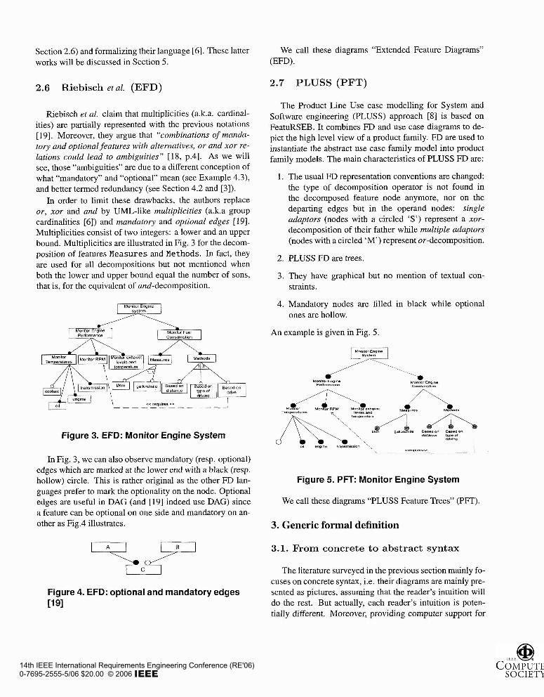
2.6 Riebisch et al. (EFD)
Riebisch et al. claim that multiplicities (a.k.a. cardinal- ities) are partially represented with the previous notations [19]. Moreover, they argue that "combinations of manda- tory and optional features with alternatives, or and xor re- lations could lead to ambiguities" [18, p.41. AS we will see, those "ambiguities" are due to a different conception of what "mandatory" and "optional" mean (see Example 4.3), and better termed redundancy (see Section 4.2 and [3]).
In order to limit these drawbacks, the authors replace or, xor and and by UML-like multiplicities (a.k.a group cardinalities [6]) and mandatory and optional edges [19]. Multiplicities consist of two integers: a lower and an upper bound. Multiplicities are illustrated in Fig. 3 for the decom- position of features Measures and Methods. In fact, they are used for all decompositions but not mentioned when both the lower and upper bound equal the number of sons, that is, for the equivalent of and-decomposition.
Monitor Engtne El Monltor Englne Performance
Monltor Fuel
cc requires ,s _ _ _ _ _ _ - _ _ - - - A
Figure 3. EFD: Monitor Engine System
In Fig. 3, we can also observe mandatory (resp. optional) edges which are marked at the lower end with a black (resp. hollow) circle. This is rather original as the other FD lan- guages prefer to mark the optionality on the node. Optional edges are useful in DAG (and [I91 indeed use DAG) since a feature can be optional on one side and mandatory on an- other as Fig.4 illustrates.
Figure 4. EFD: optional and mandatory edges 11 91
We call these diagrams "Extended Feature Diagrams" (EFD).
2.7 PLUSS (PFT)
The Product Line Use case modelling for System and Software engineering (PLUSS) approach [8] is based on FeatuRSEB. It combines FD and use case diagrams to de- pict the high level view of a product family. FD are used to instantiate the abstract use case family model into product family models. The main characteristics of PLUSS FD are:
I . The usual FD representation conventions are changed: the type of decomposition operator is not found in the decomposed feature node anymore, nor on the departing edges but in the operand nodes: single adaptors (nodes with a circled 'S') represent a xor- decomposition of their father while multiple adaptors (nodes with a circled 'M') represent or-decomposition.
2. PLUSS FD are trees.
3. They have graphical but no mention of textual con- straints.
4. Mandatory nodes are filled in black while optional ones are hollow.
An example is given in Fig. 5.
Monitor Engine
H..
Figure 5. PFT: Monitor Engine System
We call these diagrams "PLUSS Feature Trees" (PFT).
3. Generic formal definition
3.1. From concrete to abstract syntax
The literature surveyed in the previous section mainly fo- cuses on concrete syntax, i.e. their diagrams are mainly pre- sented as pictures, assuming that the reader's intuition will do the rest. But actually, each reader's intuition is poten- tially different. Moreover, providing computer support for
14th IEEE International Requirements Engineering Conference (RE'06)0-7695-2555-5/06 $20.00 © 2006
these notations requires to make everything explicit. The first step in this chain is to have a bidirectional conversion from the concrete syntax (what the user sees), to the data structures stored in the computer, called abstract syntax1.
The abstract syntax is usually a graph. It is thus essential to specify exactly what are the allowed graphs. There are two common ways to provide this information: (1) mathe- matical notation (set theory) or (2) meta-model (usually, a UML Class Diagram complemented with OCL constraints). In this paper, we follow [I I] and adopt the former for its improved conciseness, rigour and suitability for performing mathematical proofs (see [20]). The latter might be more readable and facilitate some implementation tasks such as building a repository.
All FD are graphs whose nodes are features. They were drawn as (boxed) strings or filled circles in the concrete FD languages. Many authors use the word "feature" ambigu- ously, sometimes to mean a node, sometimes a leaf (a node that is not further decomposed), and sometimes as a real- world feature. Here, we use the term "feature" as a syn- onym of "node".
We further distinguish "primitive" and "compound fea- t~res".~"rimitive features are "features" that are of in- terest per se, and that will influence the final product. On the contrary, compound features are just intermediate nodes used for decomposition. For generality, we leave it to the modeler to define which nodes in the FD have such a pur- pose. Primitive features are thus not necessarily equivalent to leaves, though it is the most common case.
What we call edges is an abstraction for the arrows and line segments we find in concrete FD. Edges always relate two nodes. We further distinguish between decomposition edges and constraint edges. The former are the edges used to relate a node bearing an operator such as or, xor or and to one of its operand nodes. The latter are used to repre- sent "graphical constraints" between two nodes, such as "re- quires" or "mutex". To determine whether a FD is a tree or a DAG, only decomposition edges are taken into account. More edge types can be found in the literature, but only edges that influence the allowed combinations of features are considered in this work.
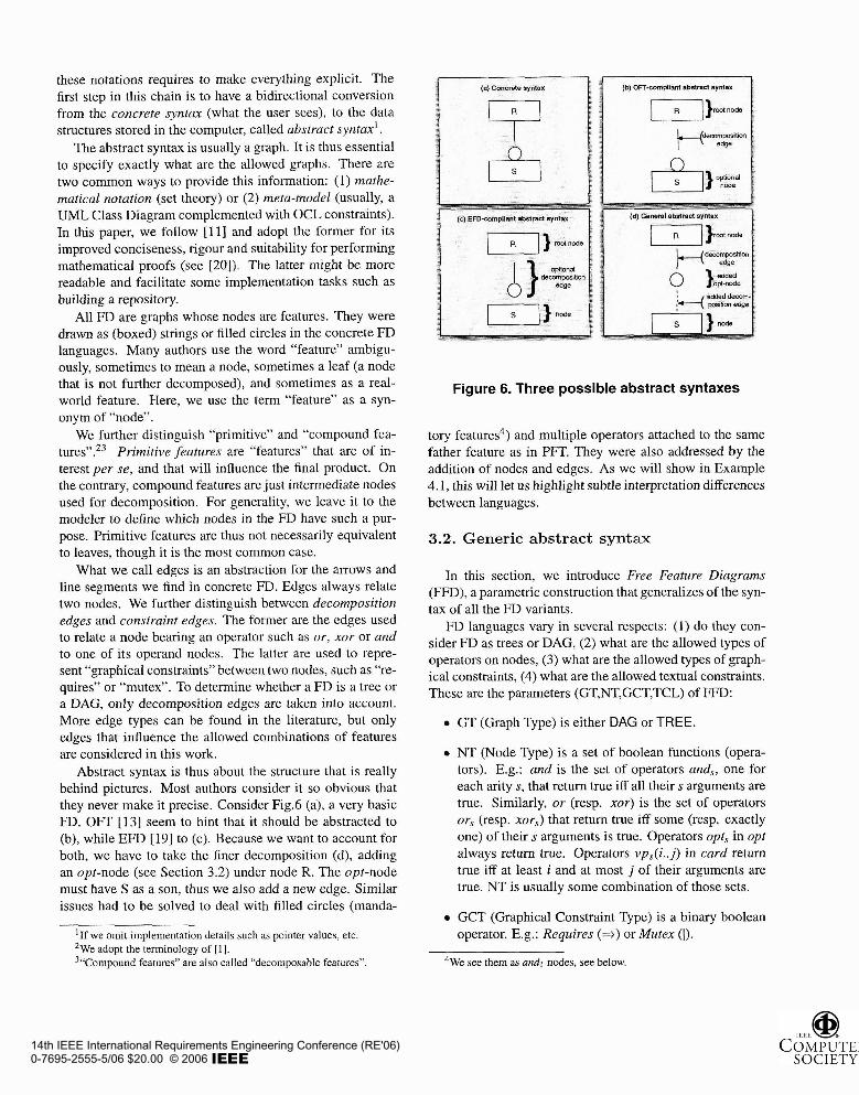
Abstract syntax is thus about the structure that is really behind pictures. Most authors consider it so obvious that they never make it precise. Consider Fig.6 (a), a very basic FD. OFT [13] seem to hint that it should be abstracted to (b), while EFD [19] to (c). Because we want to account for both, we have to take the finer decomposition (d), adding an opt-node (see Section 3.2) under node R. The opt-node must have S as a son, thus we also add a new edge. Similar issues had to be solved to deal with filled circles (manda-
'1f we omit implementation details such as pointer values, etc. *we adopt the terminology of [I]. 3"~ornpound features" are also called "decomposable features".
Figure 6. Three possible abstract syntaxes
tory features4) and multiple operators attached to the same father feature as in PFT. They were also addressed by the addition of nodes and edges. As we will show in Example 4.1, this will let us highlight subtle interpretation differences between languages.
3.2. Generic abstract syntax
In this section, we introduce Free Featztre Diagrams (FFD), a parametric construction that generalizes of the syn- tax of all the FD variants.
FD languages vary in several respects: (1) do they con- sider FD as trees or DAG, (2) what are the allowed types of operators on nodes, (3) what are the allowed types of graph- ical constraints, (4) what are the allowed textual constraints. These are the parameters (GT,NT,GCT,TCL) of FFD:
GT (Graph Type) is either DAG or TREE.
NT (Node Type) is a set of boolean functions (opera- tors). E.g.: and is the set of operators and,, one for each arity s, that return true iff all theirs arguments are true. Similarly, or (resp. xor) is the set of operators or, (resp. xor,) that return true iff some (resp. exactly one) of their s arguments is true. Operators opt, in opt always return true. Operators ~ p , ~ ( i . . j) in card return true iff at least i and at most j of their arguments are true. NT is usually some combination of those sets.
GCT (Graphical Constraint Type) is a binary boolean operator. E.g.: Requires (j) or Mutex (I).
4 ~ e see them as and, nodes, see below.
14th IEEE International Requirements Engineering Conference (RE'06)0-7695-2555-5/06 $20.00 © 2006
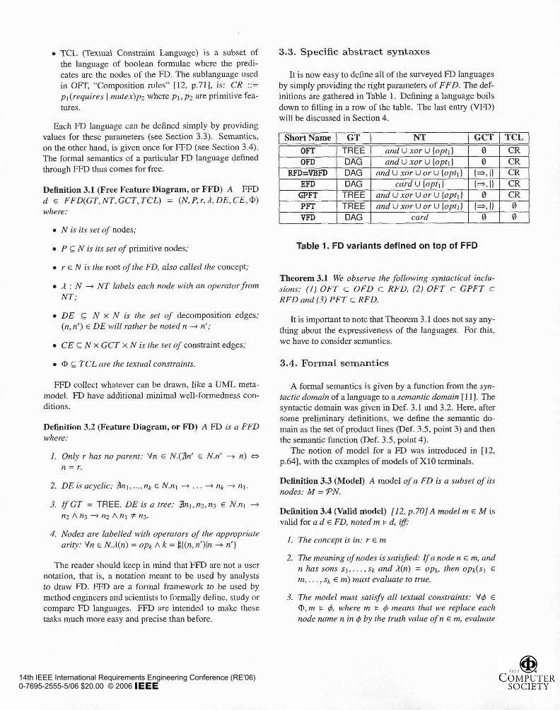
TCL (Textual Constraint Language) is a subset of the language of boolean formulae where the predi- cates are the nodes of the FD. The sublanguage used in OFT, "Composition rules" [12, p.711, is: CR ::= p1 (requires ) mutex)pz where pl, p2 are primitive fea- tures.
Each FD language can be defined simply by providing values for these parameters (see Section 3.3). Semantics, on the other hand, is given once for FFD (see Section 3.4). The formal semantics of a particular FD language defined through FFD thus comes for free.
Definition 3.1 (Free Feature Diagram, or FFD) A FFD d G FFD(GT,NT,GCT,TCL) = (N,P,r,R,DE,CE,@) where:
N is its set of nodes;
P c N is its set of primitive nodes;
r E N is the root of the FD, also called the concept;
R : N -t NT labels each node with an operator from NT;
DE c N x N is the set of decomposition edges; (n, n') E DE will rather be noted n + n';
CE G N x GCT x N is the set of constraint edges;
CD TCL are the textual constraints.
FFD collect whatever can be drawn, like a UML meta- model. FD have additional minimal well-formedness con- ditions.
Definition 3.2 (Feature Diagram, or FD) A FD is a FFD where:
I . Only r has no parent: Vn G N.($nf E N.nt + n) a n = r.
2. DE is acyclic: $nl, ..., nk E N.nl -t . . . -t nk -+ n ~ .
3. I f GT = TREE, Dl? is a tree: $nl, n2,n3 E N.nl -t
n2 A n3 + n2 A nl # n3.
4. Nodes are labelled with operators of the appropriate arify: Vn E N./l(n) = opk /\ k = #((n, n')Jn -+ n')
The reader should keep in mind that FFl3 are not a user notation, that is, a notation meant to be used by analysts to draw FD. FFD are a formal framework to be used by method engineers and scientists to formally define, study or compare FD languages. FFD are intended to make these tasks much more easy and precise than before.
3.3. Specific abstract syntaxes
It is now easy to define all of the surveyed FD languages by simply providing the right parameters of FFD. The def- initions are gathered in Table 1. Defining a language boils down to filling in a row of the table. The last entry (VFD) will be discussed in Section 4.
1 Short Name 1 GT 1 NT I GCT I TCL
I . - -
EFD I DAG I card U (optl) (*,I) ( CR GPFT 1 TREE 1 and u x o r Uor U loot~l 1 0 1 CR
- - - - - . - .. -
OFT OFD
RFD=VBFD
1 I . * -.
PFT I TREE I and U xor Uor U loot11 1 (*.I1 1 0 1 I I . . A , I . , . , ,
VFD I DAG 1 card 1 ° 1 0
. -
TREE DAG DAG
Table 1. FD variants defined on top of FFD
Theorem 3.1 We observe the following syntactical inclu- sions: (1) OFT c OFD c RFD, (2) OFT c GPFT c RFD and (3) PFT c RFD.
and U xor U {opt]) and U xor U (opt])
and U xor U or u {optl)
It is important to note that Theorem 3.1 does not say any- thing about the expressiveness of the languages. For this, we have to consider semantics.
3.4. Formal semantics
0 0
(*, I)
A formal semantics is given by a function from the syn- tactic domain of a language to a semantic domain [ I I ] . The syntactic domain was given in Def. 3.1 and 3.2. Here, after some preliminary definitions, we define the semantic do- main as the set of product lines (Def. 3.5, point 3) and then the semantic function (Def. 3.5, point 4).
The notion of model for a FD was introduced in [12, p.641, with the examples of models of XI0 terminals.
CR CR CR
Definition 3.3 (Model) A model of a FD is a subset of its nodes: M = PN.
Definition 3.4 (Valid model) [I 2, p. 701 A model m E M is valid for a d E FD, noted m k d, i f i
I . The concept is in: r E rn
2. The meaning of nodes is satisfied: Ifa node n E m, and n has sons sl , . . . , sk and R(n) = opk, then opk(sI E m, . . . , sk E m) must evaluate to true.
3. The model must satisfy all textual constraints: V4 E @, m K 4, where m K 4 means that we replace each node name n in 4 by the truth value of n E m, evaluate
14th IEEE International Requirements Engineering Conference (RE'06)0-7695-2555-5/06 $20.00 © 2006

q5 and get true. For example, if we call $1 the CR con- straint pl requires p ~ , we say that m k 41 when pl E m + p2 E m is true.
4. The model must satisSy all graphical constraints: V(n1, o p ~ , nz, ) E CE, opz(nr E m, n2 E m) must be true.
5. I f s is in the model and s is not the root, one of its parents n, called its justification, must be too: V s E
N . s ~ m A s f r : 3 n € N : n € m A n - + s .
Note that in [20] we also give a simplified version of the above definition for the specific case of tree languages. It has the advantage of being compositional, which highly facilitates implementation. However, it is less generic since it does not account for DAG.
Definition 3.5 (Product and Product Line, or PL) We define:
I . A product c is a set of primitive nodes: c E PP.
2. The product named by a model m, noted Em]], is m n P.
3. A product line (PL) pl is a set of products: pl E W P .
4. The product line of a FD d consists of the products named by its valid models: Ed] = (in n Plm I: d )
4. Discussion
Defining a formal semantics, as we just did, provides several significant benefits.
4.1. Shared understanding of FD
First, it gives the opportunity to uncover some important issues that might well remain unnoticed with only an infor- mal semantics. Here are a few examples:
Figure 7. Node- vs. edge-based semantics
Example 4.1 According to our semantics, the two FD in Fig. 7 are not eguivalenp. The left one (in OFTsyntax) has models and products (r, x, y, 1, n) and {r, x, y, m ) while the right one (in EFD syntax) has the additional models and products (r, x, y, I, m) and {r, x, y, m, n ) which is the "edge- based" semntics hinted in [19].
Example 4.2 In our semantics, Fig. 3 admits a model with neither l/km nor gallon/mile. This is clearly not the se- mantics intended in [19]. We simply suggest to remove the harmful hollow circles.
Example 4.3 Our semantics also contradicts the sentence: "All mandatory features are part of all [models]"[22, p.21. Our notion of "mandatory" is only relative to the incoming edge(s), thus a mandatory feature (node) will not be part of the model if none of its fathers is. However, in the same papel; the authors seem to agree with our interpretation. Indeed, in Fig. 8, extracted from /22, Fig. 31, Email is mandatory, but they make clear that it is not included in models where Net is not present.
lyiy Video System ,
'. Concept Node
Figure 8. RFD example from [22, Fig.31
If such issues are not made explicit and solved before a language is made public (resp. building tools), interpre- tations of the user (resp. developer) might differ from the intended one, possibly leading to misunderstandings and faulty developments, as already pointed out in the introduc- tion. It is important to note, however, that we do not claim to have provided the right semantics for all languages. We have followed OFT, which turned out to be free of ambigui- ties. OFT'S variants are not that precise nor arnbiguity-free. We therefore had to make decisions which, maybe, are not the intended ones. But at least, we have exposed them pre- cisely, concisely and hopefully without ambiguity. Now, they can thus be discussed constructively by their propo- nents and their respective user communities.
4.2. Comparing FD languages
A second advantage of formal semantics is that it makes it possible to compare languages according to formally de-
- - -
5~ssuming all features are primitive.
14th IEEE International Requirements Engineering Conference (RE'06)0-7695-2555-5/06 $20.00 © 2006

fined criteria instead of loosely defined ones. In this section and in Section 4.3, we mention some of the results that were obtained on the basis of our formalization. The full devel- opments, including mathematical proofs, can be found in [20] but are skipped here for sake of space.
One important criteria is expressiveness. Unlike most of the surveyed authors, we use the formal, well established definition of expressiveness of a language as the part of its semantic domain that it can express.
Definition 4.1 (Expressiveness) The expressiveness of a language f is the set E(C) = {[aid E L], also noted [LJ. A Language f1 is more expressive than a language C2 if E(Ll) 3 E(L2). A language L: with semantic domain M (i.e. its semantics is I[.] : L: -t M) is fully expressive if E(C) = M.
The usual way to prove that a language L2 is at least as expressive as L1 is to provide a translation from L1 to f 2:
Definition 4.2 (Translation) A translation is a tofal func- tion T : L1 -t L2 that is correct, i.e. preserves semantics: UT(d)ll = Ildll-
The semantic domain of FD are product lines (Def. 3.5). Thus, every FD expresses a PL. Now, we can ask the con- verse question: Can every PL be expressed by a FD of a given kind? Stated otherwise: is this language fully expres- sive?
In 1201, we have proved formally that this is usually false for tree languages (OFT, GPFT, PFT), and true when shar- ing is allowed, that is in DAG (OFD, EFD, RFD). This important point has been largely overlooked in literature. More precisely, our result shows that the disjunction of fea- tures cannot be expressed in OFT. In [lo], Griss et al. have proposed to solve this problem by (I) adding or-nodes, and (2) considering FD as single-rooted DAG rather than trees. We proved that the second extension alone guarantees full expressiveness while adding or-nodes only does not. It should also be noted that the limited expressiveness of tree languages can be seen as a weakness of the constraint lan- guage. If nesting of constraints were allowed, Sheffer [21] has shown that mutex alone is complete, even on primitive features only. So, using propositional logic with feature trees as in [I] provides full expressiveness.
As we just saw, DAG are fully expressive. We thus need a finer yardstick than expressiveness to compare them. The situation is similar for programming languages, that are al- most all Turing-complete and therefore have the same ex- pressiveness. Two finer criteria are well established: suc- cinctness and naturalness (a.k.a. embeddability). Intu- itively, a language L is embeddable into C2 iff a semantic- and structure-preserving translation exists from L1 to L2 29, 141. When a language Ll is embeddable into a sublanguage
L2 c L1 with the same expressiveness, L1 is said to be harmully redundant. Stated otherwise: L1 is unnecessar- ily complex because it contains at least one construct that is easily definable using only a strict subset of its own con- structs. In [20], we have shown that Om) have harmfully redundant optional nodes and textual mutual exclusion con- straints. Similarly, EFD have redundant optional edges and textual mutual exclusion constraints. Also, and-, or-, xor- and opt-nodes as well as mutex constraints are harmfully redundant wrt vp-nodes (see Table 2).
Table 2. Embedding RFD into VFD
With succinctness, we formally measure the blow-up caused by a change of notation. The most important result here is that a notation that uses vp as node operators (e.g. EFD) is more succinct than OFD, RFD or VBFD.
These results have lead us to propose a new language, called VFD (Varied Feature Diagrams) defined so as to have the best ranking on all criteria: its is fully expressive, harm- fully irredundant and can embed all other known variants and is at the same level of succinctness as EFD. It is de- fined on the last line of Table 1 and further discussed in the conclusion.
4.3. Implementing decision procedures
Finally, formalization also allows to clearly define some decision problems that need to be solved to automate FD re- lated activies and to study their computational complexity. Three recurrent PL engineering activities are: (1) modelling a PL, (2) determining a product to be built and (3) manag- ing PL evolution.
During activities 1 and 2, a FD is edited. In particular, in activity 2, the FD is "pruned" by adding constraints that eventually will lead to a single product. In both cases, from time to time, it is important to check whether the modified FD can still lead to some product. This problem is called checking sati.$ability (i.e. whether [dl # 0). The problem is NP-complete for all useful fully expressively notations, but with linear-time algorithms for some degenerated cases e.g. for trees with and-, xor-, vp-, or-nodes.
For activity 2, it is also possible for the customer or mar- ket expert to select in advance the features of the prod- uct and to check whether it is allowed or not in the PL, i.e. whether it contains feature interferences. This prob- lem (c E [dl) is called product checking and is also NP- complete.
14th IEEE International Requirements Engineering Conference (RE'06)0-7695-2555-5/06 $20.00 © 2006
The evolution of a PL (activity 3) can also be supported by tools. For example, one might want to refactor an overly complex FD into a simpler one. Or, two (versions of the same) FD representing the same PL that coexist must now be merged. In both cases, it is important to be able to check the equivalence of two FD ([Id,] = [ I d2 ] ) Deciding it turned out to be nl -complete6.
Evolution also makes it necessary to be able to merge PL but this has a rather broad meaning. More rigorously, and depending on how conservative the engineers want to be about the result, one of three operations must be chosen: in- tersection, union (a.k.a. disjunction) or reduced product of two FD. Intersection ([dl] n (Idzn) excludes all the feature interactions already excluded in each of the source FD. It is the safest option and can be used, for example, to combine the contributions of two feature interference engineers who have worked in parallel. Conversely, union ([dl] U Idz]) creates a FD that encompasses all the products of the two originating PL. It can be judged safe in some cases but may require interference checking in critical settings. A third op- tion is the reduced product ({cl U c21c1 E [dl], cz E [d2]}): it delivers a FD that not only accepts all the products from each source PL but it also generates all possible new feature combinations. The validity of these new combinations must of course be checked by feature interference engineers. The remaining combinations will allow offering the customer a wider choice. All three operations (intersection, union and reduced product) produce a FD and were proved to be com- putable in linear time and size.
Still in the context of activity 3, it may be decided at some point to change the FD language used for the PL project, for convenience or for merging it with another project that uses another language. Algorithms to translate between FD languages can be derived immediately from our embeddability and succinctness results (see e.g. Table 2). It is also important to note that these can also be applied prior to equivalence checking or merging which implies that these latter operations can be easily carried out between two FD written in different languages.
5. Related work
In this paper, we have studied the formal underpinnings of a family of languages in the line of the original feature trees [12], that have not yet received a formal definition, but where a product line semantics is clearly intended. More recently, however, a few more formally defined notations have surfaced. We briefly examine them.
van Deursen et al. 1231 define the semantics of a textual FD language by coding rewriting rules in the ASF+SDF meta-environment. Hence, contrary to ours, their semantics
6Ti1 is the first level of the polynomial hierarchy, just above NP.
is not tool-independent, nor self-contained. Another major difference is that they preserve the order of features.
Batory [I) provides a translation of FD to both grammars and propositional formulae. His goal is to use off-the-shelf Logic-Truth Maintenance Systems and SAT solvers in fea- ture modelling tools. The semantics of grammars is a set of strings, and thus order and repetition are kept. The seman- tics of propositional formulae is closer to our products but [I] differs in two respects: (i) decomposable features are not eliminated, and (ii) the translation of operators by an equiv- alence leads to (we suspect) a counter-intuitive semantics.
In [6], Czarnecki et al. define a new FD language to account for staged configuration. They introduce feature cardinality (the number of times a feature can be repeated in a product) in addition to the more usual (group) cardinal- ity. Foremost, a new semantics is proposed where the full shape of the unordered tree is important, including repeti- tion and decomposable features. The semantics is defined in a 4-stage process where FD are translated in turn into an extended abstract syntax, a context-free grammar and an al- gebra. In 151, the authors provide an even richer syntax. The semantics of the latter is yet to be defined, but is intended to be similar to [6).
Benavides et al. [2] propose to use constraint program- ming to reason on feature models. They extend the m> lan- guage of [6] with extra-functional features, attributes and relations between attributes. Subsequently, they describe tool-support based on mapping those FD to Constraint Sat- isfaction Problems (CSP).
In general, we can argue that related approaches do not rank as good as ours on generality, abstraction, conciseness and intuitiveness. For some approaches [23, 1, 21 the se- mantics is tool-driven, while on the contrary tools should be built according to a carefully chosen and well-studied semantics. For the others [6, 51, we could not find a justifi- cation. Our approach is justified by our goals: make funda- mental semantic issues of FD languages explicit in order to study their properties and rigorously evaluate them before adopting them or implement CASE tools. A finer compar- ison of the semantic options taken in the aforementioned related approaches wrt ours is a topic for future work.
A current limit of our endeavour is the scope of for- malization. As mentioned repeatedly, we focussed on PL semantics i.e. what are the allowed and forbidden feature combinations. Further formalization of aspects such as lay- ers [I 31 or binding times [24] should be further investigated.
Moreover, formality is only one specific quality of lan- guages. For example, Krogstie [I 51 proposes a comprehen- sive quality framework covering such notions as domain appropriateness (i.e. is the language considered adequate to convey the relevant information on the subject domain). A complete evaluation and comparison of FD languages should also take such aspects into account. To the best of
14th IEEE International Requirements Engineering Conference (RE'06)0-7695-2555-5/06 $20.00 © 2006
our knowledge, this remains to be done.
6. Conclusion
Throughout this paper, we have tried to clarify feature di- agrams. Feature diagrams are a popular and valuable tool to engineer software product lines. In particular, they are cen- tral to the requirements engineering process and are used by a variety of stakeholders. However, after surveying past research, we have concluded that most of it had not looked enough at the foundations necessary to avoid ambiguities and to build safe and efficient took. We have thus proposed a generic formalization of the syntax and semantics of fea- ture diagrams which, we hope, can be the basis for more rigorous investigations in the area. We have started such investigations ourselves by formally comparing languages and studying decision procedures. On these grounds, a nat- ural further step is the development of tools. Such tools will be able to operate on multiple feature diagram languages and support a large spectrum of activities. They will be cen- tered around VFD (Varied Feature Diagrams), suggested in this paper, but which need more work in several respects including a concrete syntax and empirical validation.
References
[I] D. S. Batory. Feature Models, Grammars, and Propositional Formulas. In Obbink and Pohl [16], pages 7-20.
[2] D. Benavides, P. Trinidad, and A. R. CortCs. Automated Reasoning on Feature Models. In 0. Pastor and J. F. e Cunha, editors, CAiSE, volume 3520 of Lecture Notes in Computer Science, pages 491-503. Springer, 2005.
[3] Y. Bontemps, P. Heymans, P.-Y. Schobbens, and J.-C. Tri- gaux. Semantics of feature diagrams. In T. Mannisto and J. Bosch, editors, Proc. of Workshop on Software Variabil- ity Management for Product Derivation (Towards Tool Sup- port), Boston, August 2004.
[4] S. Cohen, B. Tekinerdogan, and K. Czarnecki. A case study on requirement specification: Driver Monitor. In Workshop on Techniques for Exploiting Commonality Through Vari- ability Management at the Second Intemational Conference on Software Product Lines (SPLC2), 2002.
[S] K. Czarnecki, S. Helsen, and U. Eisenecker. Staged Config- uration Using Feature Models. Software Process Improve- ment and Practice, special issue on Software Variability: Process and Management, 10(2):143 - 169,2005.
[6] K. Czarnecki, S. Helsen, and U. W. Eisenecker. Formal- izing cardinality-based feature models and their specializa- tion. Software Process: Improvement and Practice, 10(1):7- 29, 2005.
[7] U. W. Eisenecker and K. Czarnecki. Generative Program- ming: Methods, Tools, and Applications. Addison-Wesley, 2000.
[8] M. Eriksson, J. Borstler, and K. Borg. The PLUSS Approach - Domain Modeling with Features, Use Cases and Use Case Realizations. In Obbink and Pohl[16], pages 33-44.
[9] M. Felleisen. On the expressive power of programming lan- guages. In N. D. Jones, editor, Proceedings of the Third European Symposium on Programming, volume 432 of Lec- ture Notes in Computer Science, pages 134-151. Springer Verlag, 1990.
[lo] M. Griss, J. Favaro, and M. dlAlessandro. Integrating Fea- ture Modeling with the RSEB. In Proceedings of the Fifth International Conference on Software Reuse, pages 76-85, Vancouver, BC, Canada, June 1998.
[I 11 D. Harel and B. Rumpe. Meaningful Modeling: What's the Semantics of "Semantics"? IEEE Computer, 37(10):64-72, October 2004.
[12] K. Kang, S. Cohen, J. Hess, W. Novak, and S. Peter- son. Feature-Oriented Domain Analysis (FODA) Feasibility Study. Technical Report CMU/SEI-90-TR-21, Software En- gineering Institute, Carnegie Mellon University, Nov. 1990.
[I31 K. C. Kang, S. Kim, J. Lee, and K. Kim. FORM: A Feature- Oriented Reuse Method. In Annals of Software Engineering 5, pages 143-168,1998.
[14] S. C. Kleene. Introduction to Metamathematics, volume 1 of Bibliotheca Mathematica. North-Holland, Amsterdam, 1952.
[15] J. Krogstie. A Semiotic Approach to Quality in Require- - - ments Specifications. In Organizational Semiotics, pages 231-249,2001.
[16] J. H. Obbink and K. Pohl, editors. SofnYare Product Lines, 9th Intemational Conference, SPLC 2005, Rennes, France, September 26-29, 2005, Proceedings, volume 3714 of Lec- ture Notes in Computer Science. Springer, 2005.
[17] K. Pohl, G. Bockle, and F. van der Linden. Software Product Line Engineering: Foundations, Principles and Techniques. Springer, july 2005.
[18] M. Riebisch. Towards a More Precise Definition of Feature Models. Position Papel: In: M. Riebisch, J. 0. Coplien, D. Streitferdt (Eds.): Modelling Variability for Object-Oriented Product Lines, 2003.
[19] M. Riebisch, K. Bollert, D. Streitferdt, and I. Philippow. Ex- tending Feature Diagrams with UML Multiplicities. In Pro- ceedings of the Sixth Conference on Integrated Design and Process Technology (IDPT2002), Pasadena, CA, June 2002.
[20] I?-Y. Schobbens, P. Heymans, J.-C. Trigaux, and Y. Bon- temps. Generic Semantics of Feature Diagrams. Techni- cal report, Computer Science Institute, University of Namur, 2005.
[21] H. M. Sheffer. A set of five independent postulates for boolean algebras, with application to logical constants. Trans. AMS, 14:481-488, 1913.
[22] D. Streitferdt, M. Riebisch, and I. Philippow. Formal Details of Relations in Feature Models. In Proceedings 10th IEEE Symposium and Workshops on Engineering of Computer- Based Systems (ECBS'03), Huntsville, Alabama, USA, April 7-11, 2003, pages 297-304. IEEE Computer Society Press, 2003.
[23] A. van Deursen and P. Klint. Domain-Specific Language Design Requires Feature Descriptions. Journal of Comput- ing and Information Technology, 10(1):1-17,2002.
[24] J. van Gurp, J. Bosch, and M. Svahnberg. On the Notion of Variability in Software Product Lines. In Proceedings of the Working IEEEPFIP Conference on Software Architec- ture (WZCSA'OI), 2001.
14th IEEE International Requirements Engineering Conference (RE'06)0-7695-2555-5/06 $20.00 © 2006