Defense Technical Information Center Compilation Part Notice were performed under a joint research...
25
UNCLASSIFIED Defense Technical Information Center Compilation Part Notice ADP010723 TITLE: Selected Data Set from Static and Rolling Experiments on a 65 Deg. Delta Wing at High Incidence DISTRIBUTION: Approved for public release, distribution unlimited This paper is part of the following report: TITLE: Verification and Validation Data for omputational Unsteady Aerodynamics [Donnees de verification et de valadation pour 1'aerodynamique instationnaire numerique] To order the complete compilation report, use: ADA390566 The component part is provided here to allow users access to individually authored sections f proceedings, annals, symposia, ect. However, the component should be considered within he context of the overall compilation report and not as a stand-alone technical report. The following component part numbers comprise the compilation report: ADPO10704 thru ADPO10735 UNCLASSIFIED
-
Upload
nguyencong -
Category
Documents
-
view
212 -
download
0
Transcript of Defense Technical Information Center Compilation Part Notice were performed under a joint research...

UNCLASSIFIED
Defense Technical Information CenterCompilation Part Notice
ADP010723TITLE: Selected Data Set from Static and RollingExperiments on a 65 Deg. Delta Wing at HighIncidence
DISTRIBUTION: Approved for public release, distribution unlimited
This paper is part of the following report:
TITLE: Verification and Validation Data for
omputational Unsteady Aerodynamics [Donnees deverification et de valadation pour1'aerodynamique instationnaire numerique]
To order the complete compilation report, use: ADA390566
The component part is provided here to allow users access to individually authored sections
f proceedings, annals, symposia, ect. However, the component should be considered within
he context of the overall compilation report and not as a stand-alone technical report.
The following component part numbers comprise the compilation report:
ADPO10704 thru ADPO10735
UNCLASSIFIED

383
16E. SELECTED DATA SET FROM STATIC AND ROLLING EXPERIMENTSON A 650 DELTA WING AT HIGH INCIDENCE
X.Z. Huang, T.C. Lui and E.S. HanffIAR/NRC, Canada
INTRODUCTION
This data set is selected from an extensive set of experimental results obtained for configurations with a 650delta wing under static as well as large-amplitude high-rate rolling or pitching conditions at high incidence. Theexperiments were performed under a joint research program on "Non-Linear Aerodynamics under DynamicManeuvers" by the National Research Council of Canada (NRC (IAR)), the U.S. Air Force (USAF (AFOSR,AFRL)) and the Canadian Dept. for National Defence (DND). NASA Ames informally participated in the programthrough its substantial CFD work on specific test conditions. The experimental results provide both detail pressuremeasurements and a wide range of flow conditions covering from simple attached flow, through fully developedvortex and vortex burst flow, up to fully-stalled flow at very high incidence. Since this data set includes differentlevels of physical difficulty, the computational researchers working in unsteady aerodynamics can use it as astaircase approach to the problem of validating their corresponding code. Four schematic and representativeconfigurationsI were selected in the experiments (Fig. I to Fig. 3):
1) 65' delta wing;2) 80/65' double delta wing;3) 650 delta wing with a single vertical tail and a circular ogive forebody,4) 650 delta wing with a single vertical tail and an elliptical cross section forebody whose major axis could be
installed either horizontally or vertically.
Experiments with the above models include the following test parameters:
1) motion variables (rolling or pitching),2) modes (static or dynamic),3) motion waveform (harmonic, ramp-and-hold, free-to-roll and "forced" free-to-roll),4) observed variables (flow visualization, motion history, steady and unsteady loads and surface pressure),5) wind tunnel interference assessment (by repeat tests in different wind tunnels),6) support interference assessment (by repeat tests with different supports).
The words of "forced" free-to-roll refer to the experiments performed in the forced mode with the same motionas observed under free-to-roll condition so that the unsteady surface pressures prevailing during free-to-roll motionscould be obtained.
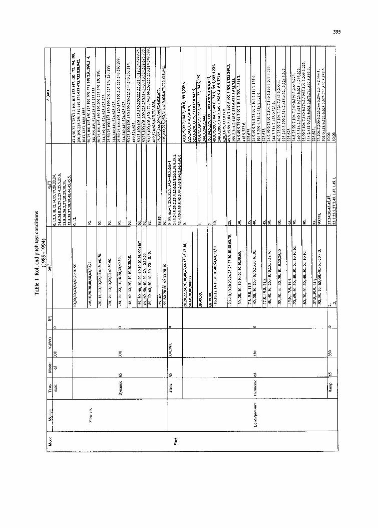
Fig. 4 to Fig. 7 show the installation and support arrangements in the two wind tunnels. The models, rolling rigand pitching rig were designed by IAR. Experiments were conducted both at the IAR and AFRL wind tunnels(LSWT and SARL respectively) and Table 1 summarizes the test matrix. A complete list of tests withcorresponding conditions can be found in Ref. 1-4. The comparisons of repeat tests conducted in different windtunnels and supports shown in Ref. 1 confirm that both wind-tunnel as well as support interference are negligible.
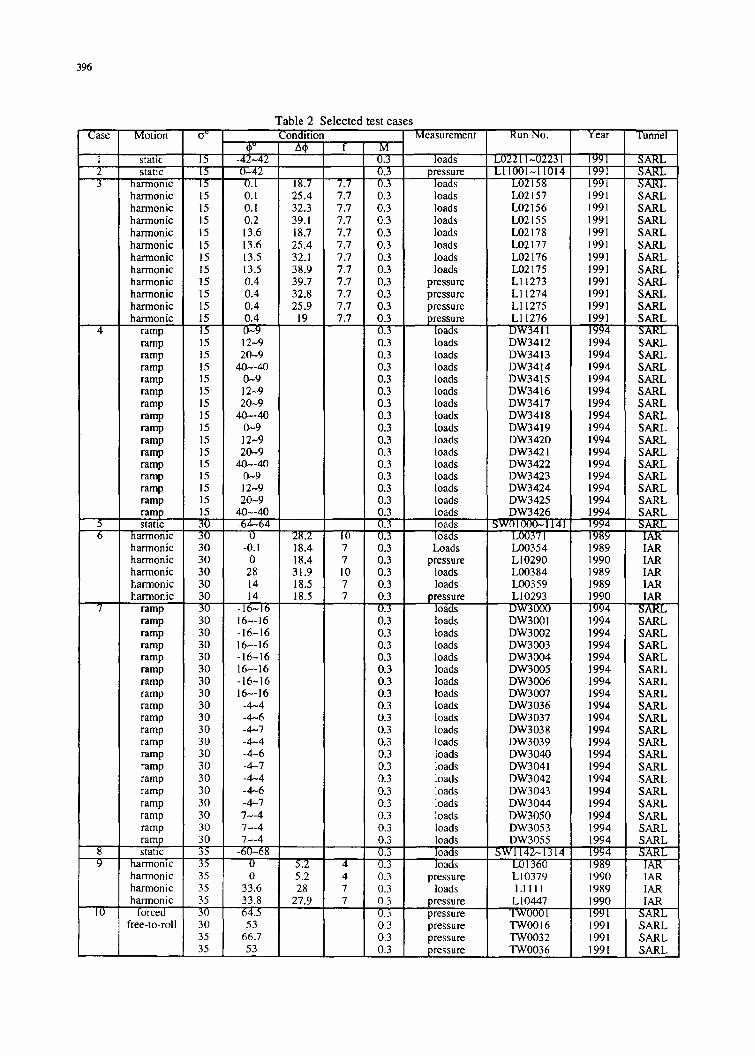
Due to large number of tests conducted, this data set contains only ten typical cases for the 65' delta wing,listed in Table 2. These cases were selected to cover typical sets of tests such as static tests and harmonic, ramp-and-hold, free-to-roll and "forced" free-to-roll dynamic tests. Seven spanwise-distributed surface pressuretransducers on the up surface of the port wing were used to measure the instantaneous surface pressure during themotion. Three typical sting angles: 7=15°, 30' and 350 were selected as being representative of different leading-edge vortex behavior. In the absence of sideslip, at 7=150 the leading-edge vortex is intact over the full length ofthe model, leading to small non-linearities and time dependence; at 0Y=30' vortex breakdown occurs over the aftpart of the wing leading to severe non-linearities and time dependence; and finally, at <T=35' vortex breakdown ispresent over the forward portion of the wing resulting in different characteristics.
LIST OF SYMBOLS AND DEFINITIONS
B wing span, (in)
c chord, (in)
co mean aerodynamic chord, (in)

384
CP pressure coefficient =(p-p0)/qs
CPi pressure coefficient measured from transducer at '"T station
C, rolling moment coefficient =I/qsB
C,. pitching moment coefficient =mrqsco
CN normal force coefficient =N/qs
CP pressure coefficient =(p-po)/qs
CPi pressure coefficient measured from transducer at "i" station
f frequency, (Hz)
k reduced frequency =nfB/Vo
t rolling moment, (lbs-in)
M Mach number
m pitching moment related to 35% MAC, (lbs-in)
N normal force, (lbs)
n yawing moment related to 35% MAC, (lbs-in)
p pressure, (psi)
PO free stream static pressure, (psi)
Pam• atmospheric pressure (psi)
q dynamic pressure, (psi)
s wing area, (in2)
S local semi-span, (in)
TO static temperature, (°C)
t time, (sec)
V0 free stream velocity, (ft/sec)
x,y,z body axes coordinates
XcP center of pressure in x axis, (in)
Ycp center of pressure in y axis, (in)
Y side force, (lbs)
a angle of attack, (0)
a sting angle (between body axis and tunnel axis), (0)
Vo roll angle, (0)
00 mean roll angle or initial roll angle, (°)
01 roll angle at end of ramp-and-hold motion, (0)
4ý roll angle in free-to-roll motion at wind-off condition, (0)
0, roll angle in free-to-roll motion at wind-on condition, (0)
AO amplitude, (0)
* roll angular rate, (rad/sec)
non-dimensional rolling frequency = ýB / 2Vo
FORMULARY
General Description of model
1.1 Designation IAR/AFRL 650 delta wing
1.2 Type Full model
1.3 References Ref. 1 (Fig. 1 to Fig. 3)

385
2 Model Geometry
2.1 Planform Delta wing
2.2 Aspect ratio 1.866
2.3 Leading edge sweep 650
2.4 Trailing edge sweep 00
2.5 Span 22.835 in
2.6 Root chord 24.485 in
2.7 Area of planform 279.486 in2
2.8 Twist 00
2.9 Leading-edge bevel (leeward) 100 (perpendicular to leading-edge)
2.10 Leading-edge bevel (windward) 10' (perpendicular to leading-edge)
2.11 Trailing edge bevel (leeward) 10' (perpendicular to trailing edge)
2.12 Trailing edge bevel (windward) 10' (perpendicular to trailing edge)
2.13 Area of planform 279.486 in2
2.14 Leading-edge radius 0.020 in
2.15 Tolerance of leading-edge radius ±10%
2.16 Mean aerodynamic chord 16.323 in
2.17 Thickness of flat area 0.375 in
2.18 Reference center 13.875 aft of the apex
2.19 Center-body diameter 3.150 in
2.20 Radius of forebody r = V24.1032 - (12.243- x) 2 - 22.528 in
3 Wind Tunnel
3.1 Designation LSWT (IAR)
3.1.1 Type of tunnel Close-circuit atmospheric type
3.1.2 Test section dimensions Height: 6 ft, width: 9ft, length: 15 ft
3.1.3 Type of roof and floor Solid with large optical quality plexiglass windows
3.1.4 Maximum speed 390 ft/sec
3.1.5 Contraction ratio 9
3.1.6 Turbulence in empty tunnel • 0.12% at free stream speed of 100 ft/sec
3.1.7 Support Sting attached to wind tunnel strut (Fig. 4)
3.1.8 Type of side walls Solid with large optical quality plexiglass windows
3.1.9 Type of roof Solid with large optical quality plexiglass windows
3.1.10 Tunnel resonance No evidence of resonance in present test
3.1.11 Reference Ref. 5
3.2 Designation SARL wind tunnel (AFRL)
3.2.1 Type of tunnel Open-circuit atmospheric type
3.2.2 Test section dimensions Height: 10 ft, width: 7ft, length: 15 ft
3.2.3 Maximum speed 660 ft/sec
3.2.4 Contraction ratio 36
3.2.5 Turbulence in empty tunnel < 0.1%
3.2.6 Type of side walls Solid with large optical quality plexiglass windows

386
3.2.7 Type of roof Solid with large optical quality plexiglass windows
3.2.8 Support Roll rig is shown in Fig. 4 and Fig. 5 while pitch rig isshown in Fig. 6 and Fig. 7
3.2.9 Tunnel resonance No evidence of resonance in present test
3.2.10 Reference Ref. 6
4 Model motion
4.1 General description Rolling about body axis with following motions:Sinusoidal (§4.6)Ramp-and-hold (§4.7)Free-to-roll and "forced" free-to-roll (§4.8)
4.2 Method of applying motion Inexorable hydraulic system (3,000 psi, 50 hp)
4.3 Model deformation Negligible
4.4 Roll angle precision 0.1750
4.5 Sting angle precision 0.10
4.6 Sinusoidal motion
4.6.1 Maximum oscillation amplitude 400
4.6.2 Maximum mean roll angle ± 500
4.6.3 Maximum frequency 18 Hz
4.7 Ramp-and hold motion
4.7.1 Waveform Constant velocity with constant acceleration at both ends,or Only constant acceleration at both ends (doubleparabola)
4.7.2 Maximum of angular rate 4500 °/sec
4.7.3 Maximum of angular acceleration 500,000 0/sec2
4.8 Free-to-roll and "forced" free-to-roll
4.8.1 Maximum initial roll angle 900
4.8.2 Tare friction Approximately constant (independent of rate)
5 Test Conditions
5.1 Model planform area/tunnel area 0.0296 (SARL) and 0.0357 (LSWT)
5.2 Model span/tunnel height 0.300 (LSWT)
5.3 Model span/tunnel width 0.272 (SARL)
5.4 Model center chord/ tunnel height 0.204 (SARL)
5.5 Model center chord/ tunnel width 0.227 (LSWT)
5.6 Blockage at a=30' 0.0148 (SARL) and 0.0179 (LSWT)
5.7 Position of model in tunnel Standard side position (LSWT)Standard upright position (SARL)
5.8 Rolling moment of inertia 0.15 lbs-in-sec 2
5.9 Range of tunnel total pressure Atmospheric (SARL)Atmospheric static pressure (LSWT)
5.10 Definition of model sting angle Angle between body axis and tunnel axis
5.11 Sting deformation under static loads Negligible in (LSWT) and lVat c7=30' in (SARL)

387
6 Measurements and Observations
6.1 Steady pressure for static conditions Yes
6.2 Unsteady pressures for dynamic Yesconditions
6.3 Steady forces for static conditions Measured directly
6.4 Unsteady forces for dynamic conditions Measured directly
6.5 Measurement of actual motion of Yesmodel
6.6 Measurement of free-to-roll motion Yeshistory
6.7 Observation or measurement of Yesboundary layer properties
6.8 Visualisation of surface flow Yes
6.9 Visualization of off-surface flow Yes
6.10 Wind tunnel interference assessment Yes
6.11 Support interference assessment Yes
7 Instrumentation
7.1 Steady pressure
7.1.1 Position of orifices spanwise and see Fig. Ichordwise
7.1.2 Type of measuring system Kulite pressure transducers (LQ-47-25A) with "B" screenOperation mode AbsoluteSensitivity range 3.21-4.46 mv/psiZero pressure output: <-5% full scale
7.1.3 Installation of transducers Using RTV adhesive flush ( .O-O ) to upper surface.
Fill trough with clear epoxy filler fair to upper surface.
7.1.4 Principle and accuracy of Kulite: static calibration at beginning of tunnel entry,calibration offset measurement every 30 minutes.
7.2 Unsteady pressure
7.2.1 Position of orifices See Fig. 1
7.2.2 Type of transducers Same as §7.1.1
7.2.3 Method and accuracy of calibration Kulite: static calibration at beginning of tunnel entry,offset measurement every 30 minutes
7.3 Steady loads7.3.1 Type of transducers Strain gauge7.3.2 Type of measuring system Five components balance with maximum range:
Normal force N=2,000 lbsSide force Y=1,000 lbsRolling moment t=3,000 lb-in
7.3.3 Method and accuracy of calibration Maximum and relative deviations:Normal force ANmax --+2 lbs, 5Nma--0.1%
Pitch moment Am ,---±5 lbs-in (Ax,,m= 0.005 in)Side force AYma, ---_2 lbs, 8Yma,=0.1%Yawing moment Anma--+5 lbs-in (Aymax= 0.005 in)Rolling moment Atma---•6 lbs-in Wte_=0.2%
7.4 Unsteady loads

388
7.4.1 Type of transducers Strain gauge
7.4.2 Measurement method Ensemble average of coherent samples taken over severalcycles
7.4.3 Method and accuracy of calibration
7.5 Model motion
7.5.1 Method of measurement Angular encoder on driveshaft aft end
7.5.2 Accuracy ±0.10
7.5.3 Sting acceleration (horiz. and vert.) Accelerometer EGA-125*-10DNon-linearity: ±1%Range: :10 gLimit: ±50 gThem.Z ±l%FSf1000 FTSS ±2.5% /100 0F
7.6 Processing of unsteady measurements
7.6.1 Pressure signal acquisition See Fig. 8a (up to 1991)
7.6.2 Loads signal acquisition See Fig. 8b (up to 1991)
7.6.3 Processing data Ensemble average over more than 30 (harmonic motion),or 9 cycles (ramp-and-hold motion)
8 Data presentation
8.1 Test cases for which data could be Table 1made available
8.2 Test cases for which data are included Table 2in this document
8.3 Data presentation See CD-ROM (in Tecplot format)
8.4 Electronic data file index Table 3
8.5 Examples of lay-out of data files Table 4 at page 23
8.6 Some illustration of results See page 17 to 22
9 Personal contact for further information
Xing Zhong Huang and Ernest S. Hanff, Aerodynamics Laboratory, Institute for Aerospace Research,National Research Council of Canada, Montreal Rd. Ottawa, Canada, K1A 0R6.e-mail address: xingzhong.huan&@nrc.ca and [email protected]
10 List of references
[1]. Hanff, E.S. and Huang, X.Z., "Rolling and Pitching Experiments on Configurations with a 650 Delta Wing at HighIncidence" NRC/IAR LTR-A-013, 1997.
[2]. Jenkins, J.E. and Hanff, E.S., "Highlights of the IARIWL Delta Wing Program" AIAA Atmospheric FlightMechanics Conference, Workshop III, August 1995
[3]. Hanff, E.S. and Jenkins, S.B., "Large-Amplitude High-Rate Roll Experiments on a Delta and Double Delta Wing,"AIAA Paper 90-0224, 1990.
[4]. Hanff, E.S., Kapoor, K, Anstey, C.R. and Prini, A., "Large-Amplitude High-Rate Roll Oscillation System for theMeasurement of Non-Linear Airloads," AIAA Paper 90-1426, 1990.
[5]. Brown, T.R., "Description of the 6-ft x 9-ft Low Speed Wind Tunnel." NRC, NAE LTR-LA-285, Nov. 1986.
[6]. Presdorf, T.A., "Subsonic Aerodynamic Research Laboratory," USAF WL-TR-92-3053, Aug., 1992.

389
Si - )r Coordinates of pressure transducers
STA. x y.13.385 -7.857
\ 4 /A \2 18.388 -7.161
65' 3 18.378 -6.5354 1-373 -5.844
C / \ 5 18.382 -5.1146/ \ 18.374 -4.442
- - 20" 7 18.381 -3.755R1 8 1i.374 +3.823
19 !8.372 +4.44903\ 0.378 +5128
11 18.379 +5.810I, 12 18.377 +8.505
/ 13 18.382 +7.13414 18.378 +7.854
STA1 ST A?7 STA.8 STA.14
PRESSURE TRANSDIUCER
12.5RGo.020 MAX.
ONCE DEFINED, TOL.=±1O%
0.3750 L 9.320
03.1 50 22,835
Mean Aerodynamic Chord =16.323 in. . 011 234 56Fig. ~ ~ ~ 0 1 15 2ct 3i~ 4 5 6
Fig. 1 65 delta wing 0SCALE (INCHES)
Coordinates of pressure transducers
STA. x Y1 18.385 -7.857
80 •2 18.388 -7.16'1
. 3 18.378 -8.5354 18.373 -5.844Y 6 ,- 1,8.382 -5 .1146 18.374 -4.4427 18.361 -317558 18.374 +3.823
65" 9 18.372 +4.449
10 18.378 +5.128•"_L1 I 18.379 +5.818
12 \i 18.377 +6.505o _M• 3_ 18.382 +7.134
d 20" 14 18.378 +7.854
0.A- 8 750 1
S03.150 2.3
Mean Aerodynamic Chord = 17.468 in. v R•15 •01 23456
D315 22.835 I
Fig. 2 800/650 double delta wing SCALE (INCHES)

390
Coordjnatau of preaaur 6.000tranuducers 40s
STA. X Y1 6.121 +7.850 20'2 6.121 +7.170 E 0
3 6.121 +48.490 2.0008
4 6.121 +5.8105 6.121 +5.1306 6.121 +4 450
7 6.121 3.770 LO8 11.347 149.8919 1.347 +?. 321 0 _ _
10 1.347 +4.75011 6121 -5.810
12 12.242 +5.233018 12.242 + 3.87314 12.242 .42513
STA.
STA.1
9 2 3STA.12
31.55 REF 4*PRESSURE TRANSDUCER
0 6 13o .7
o12.5 14
BALANCE REF. CENTRE
200
R0120'
0.98065
ONCE DEFINED, TOL.=±10Z
24.485
37.134
16.M00 16.0002.000 2.000
major body axis horizontal major body axis vertical
0 12 345 6
Fig. 3 Forebody/wing/tail model SCALE (INCHES)

391
TUNNEL CEILING
TURN TABLE CENTRE-UNE
49.57
000
I"-
24.485
TUNNEL FLOOR
0 6 12
Fig. 4 Side view of roll rig in the IAR 6 x 9 foot tunnel IS CL II,,, INCSCALE (/NCH.S)
TUNNEL CEILING
REF. CENTER & ROTATION CENTER
- __ -~ o ~?QUADRANT
00
84
Front View Side View
0 8 16 24 32
Fig. 5 Installation of roll rig in the SARL tunnel SCALE (INCHES)

392
TUNNEL CELINGR
BALA RE' F.ECTREE
0OEN REF 16E24ER
0.18 STUT 2,83Fi.7 Ge1a.ve6f1ic0rgSAL IC IS

393
PRE-GAIN BAND PASS 6 POLE POST-GAIN
AC AMPLIFIER BUTTERWORTH AC AMPLIFIER
BALANCESURPRESSURE
SIGNAL SIGNALAC-DC SIGNAL SEPERATION
INSTRUMENTATION AMPILIFIER
DC SIGNAL
ELECTRICALCALIBRATION
SIGNALPRE-GAIN LOW PASS E POLE POST-GAIN
DC AMPLIFIER BUTTERWORTH DC AMPLIFIERFILTER
Fig. 8a Signal conditioning for data acquisition used up to 1991
TEMPERATURE CONTROLLED
PRESSURE
SIGNAL
ISOLATION PRE-G.ASN
ELIETRICAL ]
Fig. 8b Signal conditioning for data acquisition used after 1991

394
0 5 A
vi o6U
on n IQn~
TL~ 0-ee~~ec4 aO 00
140 004 onc00
o? 6 n onq
-z c00
tf n 'O~n on c
ono
no- >600~ .d ', .00',oneltOS7 70 0 o
0.
000~~c 0 0
oon
onon.6 onc0
In n L ono .On~~onon ~ 1- on 00 0 1 01 N N 00~~aenen ~~ 11 fo n onL _
Acono
7800o 0o
o0 qoqT-
395
I "' IC~ 0'ý nS o6
r4 7t w0 ~0 :W 6
0~- c4 I I-I0 or I n ;
00N 4. .ý 00
I , . In0Ili In
a 00 ~ .6n~n nnn O~~ 00. -
0000 0 - cý
-:~o 0.. 1?~
.6C 025
-~ 0-is 0
396
Table 2 Selected test casesCase Motion o° Condition Measurement Run No. Year Tunnel
01° AO f M
1 static 15 -42~42 - .3 loads L02211-02231 199 SARLT2 static 15 U-=2 0.3 pressure L1T1001-1T014 T99 SRL3 harmonic 73 -- D7 18.7 -7.7 0.3 Toads L02158 1971 RL
harmonic 15 0.1 25.4 7.7 0.3 loads L02157 1991 SARLharmonic 15 0.1 32.3 7.7 0.3 loads L02156 1991 SARLharmonic 15 0.2 39.1 7.7 0.3 loads L02155 1991 SARLharmonic 15 13.6 18.7 7.7 0.3 loads L02178 1991 SARLharmonic 15 13.6 25.4 7.7 0.3 loads L02177 1991 SARLharmonic 15 13.5 32.1 7.7 0.3 loads L02176 1991 SARLharmonic 15 13.5 38.9 7.7 0.3 loads L02175 1991 SARLharmonic 15 0.4 39.7 7.7 0.3 pressure LI 1273 1991 SARLharmonic 15 0.4 32.8 7.7 0.3 pressure LI 1274 1991 SARLharmonic 15 0.4 25.9 7.7 0.3 pressure LI 1275 1991 SARLharmonic 15 0.4 19 7.7 0.3 pressure Li 1276 1991 SARL
ramp 15 0-9 0.3 loads DW3411 1994 SARLramp 15 12~9 0.3 loads DW3412 1994 SARLramp 15 20-9 0.3 loads DW3413 1994 SARLramp 15 40,,-40 0.3 loads DW3414 1994 SARLramp 15 0-9 0.3 loads DW3415 1994 SARLramp 15 12-9 0.3 loads DW3416 1994 SARLramp 15 20-9 0.3 loads DW3417 1994 SARLramp 15 40--40 0.3 loads DW3418 1994 SARLramp 15 0-9 0.3 loads DW3419 1994 SARLramp 15 12-9 0.3 loads DW3420 1994 SARLramp 15 20-9 0.3 loads DW3421 1994 SARLramp 15 40-40 0.3 loads DW3422 1994 SARLramp 15 0-9 0.3 loads DW3423 1994 SARLramp 15 12-9 0.3 loads DW3424 1994 SARLramp 15 20-9 0.3 loads DW3425 1994 SARLramp 15 40-40 0.3 loads DW3426 1994 SARLstatic 30 -64-64 0.3 loads SW01000-1141 1994 SARL
6 harmonic 3 28. 1 0 . loads L00371 1989 ITAYharmonic 30 -0.1 18.4 7 0.3 Loads L00354 1989 IARharmonic 30 0 18.4 7 0.3 pressure L10290 1990 IARharmonic 30 28 31.9 10 0.3 loads L00384 1989 IARharmonic 30 14 18.5 7 0.3 loads L00359 1989 IARharmonic 30 14 18.5 7 0.3 su L10293 1990 IAR
ramp 30 -16-16 0.3 ads DW3000 1994 SRramp 30 16-16 0.3 loads DW3001 1994 SARLramp 30 -16-16 0.3 loads DW3002 1994 SARLramp 30 16--16 0.3 loads DW3003 1994 SARLramp 30 -16-16 0.3 loads DW3004 1994 SARLramp 30 16--16 0.3 loads DW3005 1994 SARLramp 30 -16-16 0.3 loads DW3006 1994 SARLramp 30 16--16 0.3 loads DW3007 1994 SARLramp 30 -4-4 0.3 loads DW3036 1994 SARLramp 30 -4-6 0.3 loads DW3037 1994 SARLramp 30 -4-7 0.3 loads DW3038 1994 SARLramp 30 -4-4 0.3 loads DW3039 1994 SARLramp 30 -4-6 0.3 loads DW3040 1994 SARLramp 30 -4-7 0.3 loads DW3041 1994 SARLramp 30 -4-4 0.3 loads DW3042 1994 SARLramp 30 -4-6 0.3 loads DW3043 1994 SARLramp 30 -4-7 0.3 loads DW3044 1994 SARLramp 30 7--4 0.3 loads DW3050 1994 SARLramp 30 7--4 0.3 loads DW3053 1994 SARLramp 30 7--4 1 0.3 loads DW3055 1994 SARL
8 static 35 -60-68 0.3 loads SW1142-1314 1994 SARL9 harmonic 35 -T -7 0.3 loads L1360 1989 IAR
harmonic 35 0 5.2 4 0.3 pressure L10379 1990 IARharmonic 35 33.6 28 7 0.3 loads LI I 11 1989 IARharmonic 35 33.8 27.9 7 0.3 pressure L10447 1990 IAR
.forced 5 pressure TW000 I 191 SAR9free-to-roll 30 53 0.3 pressure TWOO16 1991 SARL
35 66.7 0.3 pressure TW0032 1991 SARL35 53 0.3 pressure TW0036 1991 SARL

397
Table 3 Electronic data file index
Page Case Motion Data Measurement Run No. File Name
I I static Case I (Data and Test Conditions) loads L02211-L02231 data-cs3-1-2-32 static Case 2 (Data and Test Conditions) pressure LI 1000-LI 10143 harmonic Case 3 (Test Conditions) loads/pressure
2-6 Case 3 (Data Run No. L02158) loads L02158 data-case3 / c3-27-11 Case 3 (Data Run No. L02157) loads L0215712-16 Case 3 (Data Run No. L02156) loads L0215617-21 Case 3 (Data Run No. L02155) loads L02155
22-26 Case 3 (Data Run No. L02178) loads L0217827-31 Case 3 (Data Run No. L02177) loads L02177
32-36 Case 3 (Data Run No. L02176) loads L02176
37-41 Case 3 (Data Run No. L02175) loads L0217542-46 Case 3 (Data Run No. LI 1273) pressure LI 1273 data-case3 1 c3-3
47-51 Case 3 (Data Run No. LI 1274) pressure LI 127452-56 Case 3 (Data Run No. LI 1275) pressure LI 127557-61 Case 3 (Data Run No. LI 1276) pressure LI 1276
62 4 ramp Case 4 (Test Conditions) loads data-case4 / c4-163-67 Case 4 (Data Run No. DW0341 1) loads DW03411 data-case4/ c4-268-72 Case 4 (Data Run No. DW03412) loads DW03412
73-77 Case 4 (Data Run No. DW03413) loads DW0341378-82 Case 4 (Data Run No. DW03414) loads DW0341483-87 Case 4 (Data Run No. DW03415) loads DW03415
88-92 Case 4 (Data Run No. DW03416) loads DW03416
93-97 Case 4 (Data Run No. DW03417) loads DW0341798-102 Case 4 (Data Run No. DW03418) loads DW0341 8103-107 Case 4 (Data Run No. DW03419) loads DW03419108-112 Case 4 (Data Run No. DW03420) loads DW03420
113-117 Case 4 (Data Run No. DW03421) loads DW03421118-122 Case 4 (Data Run No. DW03422) loads DW03422123-127 Case 4 (Data Run No. DW03423) loads DW03423128-132 Case 4 (Data Run No. DW03424) loads DW03424133-137 Case 4 (Data Run No. DW03425) loads DW03425138-142 Case 4 (Data Run No. DW03426) loads DW03426143-146 5 static Case 5 (Data and Test Conditions) loads SWOIOOO-01316 data-case5 / c5-1
147 6 harmonic Case 6 (Test Conditions) loads/pressure data-case6 I c6-1148-152 Case 6 (Data Run No. L00371) loads L00371 data-case6 / c6-2153-157 Case 6 (Data Run No. L00354) loads L00354158-162 Case 6 (Data Run No. L10290) pressure LI 0290 data-case6 / c6-3163-167 Case 6 (Data Run No. L00384) loads L00384 data-case6 / c6-4168-172 Case 6 (Data Run No. L00359) loads L00359173-177 Case 6 (Data Run No. L10293) pressure L10293 data-case6 / c6-5
178 7 ramp Case 7 (Test Conditions) loads data-case7 / c7-1179-183 Case 7 (Data Run No. DW03000) loads DW03000 data-case7 / c7-2184-188 Case 7 (Data Run No. DW03001) loads DW03001
189-193 Case 7 (Data Run No. DW03002) loads DW03002194-198 Case 7 (Data Run No. DW03003) loads DW03003199-203 Case 7 (Data Run No. DW03004) loads DW03004204-208 Case 7 (Data Run No. DW03005) loads DW03005209-213 Case 7 (Data Run No. DW03006) loads DW03006214-218 Case 7 (Data Run No. DW03007) loads DW03007219-223 Case 7 (Data Run No. DW03036) loads DW03036224-228 Case 7 (Data Run No. DW03037) loads DW03037

398
Table 3(cont.) Electronic data file index
Page Case Motion Data Measurement Run No. File Name
229-233 7 ramp Case 7 (Data Run No. DW03038) loads DW03038 data-case7 / c7-2
234-238 _Case 7 (Data Run No. DW03039) loads DW03039
239-243 - .Case 7 (Data Run No. DW03040) loads DW03040
244-248 Case 7 (Data Run No. DW03041) loads DW03041
249-253 Case 7 (Data Run No. DW03042) loads DW03042
254-258 Case 7 (Data Run No. DW03043) loads DW03043
259-263 Case 7 (Data Run No. DW03044) loads DW03044
264-268 Case 7 (Data Run No. DW03050) loads DW03050
269-273 Case 7 (Data Run No. DW03053) loads DW03053
274-278 ICase 7 (Data Run No. DW03055) loads DW03055
279-281 8 static Case 8 (Data and Test Conditions) SW0I 142-01262 data-case8 / c8-1
282 9 harmonic Case 9 (Test Conditions) loads/pressure data-case9 / c9- I283-287 Case 9 (Data Run No. LOl1360) loads L01360 data-case9 / c9-2
288-292 Case 9 (Data Run No. L10379) pressure L10379 data-case9 / c9-3
293-297 Case 9 (Data Run No. LO I11) loads LO 1111 data-case9 / c9-4
298-302 Case 9 (Data Run No. L10447) pressure L10447 data-case9 / c9-5
303 10 forced Case 10 (Test Conditions) pressure data-caselO / elO-1
free-to-roll 1
304-309 Case 10 (Data Run No. pressure TWOOO1 I data-case 10 / c10-2TWOOOl1 /1 T"OOOO1) TTOOCO1
310-315 Case 10 (Data Run No. pressure TW00009 / data-casel0 / c10-2
TWOOO09 / TTrOO09) "T!3OO009
316-321 Case 10 (Data Run No. pressure TW00032 / data-casel0 / c10-2
TW00032 / TT00040) ITT00040
322-327 Case 10 (Data Run No. pressure TW00046 / data-easel 0 / c 10-2
_ TWO0046 / TT00034) I TF00034_

399
0.03 2.0
C-Cp = -42
0.02 0
1.0 0
000.01 00
00 0
o0 00.5 7
0.00- oO o
0.00
-0.010 -0.5 . . .
_0.0-1 -0,5 0 0.5 i Iy/S-0.020
2.0
-0.03 I I I I I I I I -28-50 -40 -30 -20 -10 0 10 20 30 40 50 -- 0
1.5
00
0.000 00 0 00 0
Cm 0.50 0
-0.002 0 000.0
-0.004 00.5 .S-0/.5 0 0.5 S
0 0
-0.006 2.00 0 0 -Cp 0 -14
1 .5
-0.0080 0
1,0 0 0: 0 0o
-0.01 I I I I I I I I"950 -40 -30 -20 -10 0 10 20 30 40 50 0.5 0
0 000°0
0.0
1.0--0.5 I I I
CN -0.5 0 0.5 y/S
0.8
O 0 2.0
0.-CP 0 0=000.6 -1.5
0 0
04 1.00 0 0 0 0 0
0.5
0.2 0 0
0.0SI J I , I t I i I ,I I I I iI I I .
0050 -40 -30 -20 -10 0 10 20 30 40 50 -0. -0.5 0 0.5 ,I I
Fig.Case 1 Run No. L02211 - L02231 Fig.Case 2-1 Run No. 11000 - LI 1014
c= 15' P,,=13.355 psi y = 150 Po = 13.427 psi0 =-42°0- +420 T(, = 22.20 q = 0.806 psiM 0.29 M = 0.29 Patm = 14.254 psi

400
00go -*5070°
640 25
20
-20
-40 -25
-60
-80 0-05 0.1 0.15 -500 0.5 1 1.5 2t (s") t (s")
0.06 0.03CI C
0.04 0.02
0.02 0.01
0.00 0.00
-0.02 -0.01
-0.04 -0.02
- A50 40 _30 _20 _10 0 10 20 30 40 50 60 1 1.5 200t (sec)
0.04 0_000
Cm C,-0.002
0.02
0.00-0.004
-0.02
-0.02-.08!
-60 -50 -40 -30 .20 -10 0 10 20 30 40 5060 0 0.5 1 1.5 2CI (sM)
1.4 0.75CN
1.2 0.70
1.0
0.87 0.8 •0.607
0.60.55
0.4
0.2 0.50
0• �1,1I t IIIrI Ii I I I0I4560 -5 -4 -2 -I 0 0 6 I II'!'! t 0 .4 t I I 15 1 1.52- -50 -40-30-20 -100 10 20 30 40 5060 0.5Ie52o
Fig.Case 3-7 Run No. L02176 Fig.Case 4-8 Run No. DW03418
S=15' f = 7.7 cy = 15' 0 = 1 rad/sec4o= 13.645" P. = 13.427 psi 41•= 40- P0 = 13.378 psiAO = 32.176- M = 0.29 C0= -400 M = 0.29

401
006 80.00.o6 - €0.o
C, -cb.60.0
004 0
0% 40.00.02 Ao
20.0
00VL 0.0
-0.02 v C 0 -00- L...L' L-0.2 : -t 0G I I , I I I
000 0.02 0.04 0.06 0.08 0.1 0 12-0.04 o0.8t (sec)
CO 0.08
-0.06 -60 -40 -20 0 20 40 60
0.04
0.06- 0.00
Cm0.04-0.04
-
0.02- I,,1ý8O% -10 0 10 20 30 40 50 60 0.70
0.00 ; o o o
0 0 0.04- ,-0.0 2 0 0000 0 CO O 0 0. 2
o002 -ooo
-0.04-
006 I I I I I 0.00-0 -60 -40 -20 0 20 40 60
0°-0.02
2.0-
CN -10 0 10 20 30 40 50 60 70
1.6
C.0
1.2 - 2 C\j :z N. 1.5
dXI %b0.4 -. 5
0 0 I I i II I I I I I i I il , t . . I * , . . I . . l l l 1 1-60 -40 -20 0 20 40 60 0010 0 1O 20 30 40 50 60 70
Fig.Case 5 Run No. SWO1000 - 01141 Fig.Case 6-4 Run No. L00384SW01290- 01420 =300 f=10
0 = 300 P. = 13.355 psi 0,o= 27.359- Po = 14.602 psi0 = -64"- +64" M = 0.29-0.31 AO = 31.502" M = 0.264

402
20
1o
to@0
-10
20 0.2 0.4 0.6 0.8 1 1.2 1.4t (sc,:)
0.03 - 0.03CI CI
0.02 0.02
0.01 0.01
0.00 0.00
-0.01 -0.01
-0.02 -0.02
0.2 0.4 0.6 0.8 1 1-2 1.4 -0120
0.04 -0.04Cm, Cm
0.02 •0.02
0.00- 0.00
-0.02 -0.02
0 0.2 0.4 0.6 0.8 1 1.2 1.4 -20 -15 -10 -5 0 5 1o 15 020t (Se)
1.6 - 1.6
CN CN1.5 71.5
1.4 1.4
1.3 1.3
1.2d 1.2
1.1 1.1
0.2 0.4 06 08 1 1.2 1.4 -20 -15 -10 -5 0 5 10 15 20t (see) @0
Fig.Case 7-1 Run No. DW03000
y = 30' ý = 0.5 rad/sec0o= -16- Po = 13.574 psi0, = 16' M = 0.30

403
0.08 80
Cl 60
0.04 40
20-
0.00 0oj ¢O 0
-20 I I-0.040 .15-0.04 - 0.05 0.1 t0.1)
eeoo
- ~0.08t t I I t I i i l I t i I t I l C
-20 0 20 40 60 80
0.04
0.08 0.00
Cm0.04 -0.04 ,
0.04-- OY 0
Soo -10 0 10 20 30 40 50 60 700.0 1 OD ,'
%00 0.04
-0 Cm-0.04 0.02
•o0O0,002
-20 0 20 40 60 80
@0
-0.02
2.0
CN -10 0 10 20 30 40 50 60 0o70
1.6C2.00 CN
1.21.5
0.8008 1.0
00
0.4 0.5
-20 0 20 40 60 , , 80 10. 0 10 . 20 L 30 LO 401 . 501 .... 601 .'70@0.@
Fig.Case 8 Run No. SWO 1142 - 01262 Fig.Case 9-3 Run No. LO 111
350 M =-0.30 a=35° f=7-12- +68" o=28.176" Po= 14.672 psi
Po = 13.342 -13.432 psi AO = 33.646 0 M = 0.264
404
80- 0.0-
60 ~-0.5-1.0 -
40- 000-1.5 00
20- 0-2.0
02.0--~ - -2.520 100 200 300 400 500 600 ''0 10 20 30 40 500 600
t ( c)t (m sec)
0.0 0.0
-0.5 -0.5
4.0O 0000
-1.5 -1.500
-. -- 2.0 Z-00
-2.5 -2.5
03OEIiI 1OO 10 12-0101 1 3100 .... 400 500 600 0% 10 -LI 200 300 40 1* 5100' 16100t~rse t (m se
0.0- 0.0-
CP2.5 CP6-0 -0.5
-1.0 -1.0
0-1.5
0
-2.0 Z- -2.0 Z
-2.5 -2.5
-3.0 J-' -3.0 L0 100 200 300 40 500 600 0 100 200 300 400 500 600
t (m See) t (m see)
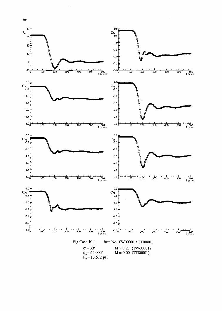
-2.5 13.525p

405
Table 4 Examples of lay-out of data files
Case I (Data and Test Conditions)
Run No. a ' C, C. CN CY C, To (°C) Po (psi) M Vo (ft/sec) q (psi) atm (psi)
L02211 15 -41.995 0.0224 -0.0054 0.502 0.01275 -0.00007 20.5 13.355 0.29 329.0 0,799 14.181
L02212 15 -28.044 0.0184 -0.0042 0.623 0.01009 -0.00025 20.5 13.355 0.29 329.0 0.799 14.181
L02213 15 -13.912 0.0113 -0.0062 0.713 0.00491 0.0003 20.5 13.355 0.29 329.0 0.799 14.181
Case 2 (Data and Test Conditions)
Run No. e' * Cp, CP2 Cp3 Cp4 Cp, Cp[ Cp7 To0 C Po(psi) M Vo(ft/sec) q (psi) atm (psi)
LII1000 151 -41.881 -0.6722 -0.7502 -0.94371 -1.3365 -0.84491 -0.1978 -0.0265 22.2 13.427 0.29 331.0 0.806 14.254
LI1001 15 -27.975 .0.7451 -0.8353 -0.9074 -1.6457 -1.0368 -0.3017 -0.0835 22.2 13.427 0.29 331.0 0.806 14.254
L11002 15 -13.909 -0.8262 -0.8823 -0.9569 -1.6905 -0.9928 -0.3431 -0.1414 22.2 113.427 0.29 331.0 0.806 14.254
Case 3 (Data Run No. L02158)
O f P. (psi) M Vo(ft/sec) q (psi)
15 -0.046 18.752 7.7 13.398 0.29 329 0.856
No. Time (sec) V0t) C, C, C C, C,
1 0.000000 18.704 -0.0163 -0.0064 0.654 -0.02070 0.001772 0.000507 18.690 -0.0165 -0.0064 0.654 -0.02088 0.00176
3 0.001015 18.666 -0.0167 -0.0064 0.654 -0.02104 0.00175
Case 3 (DataRun No. LI 1273)
00* 40,O AO0 f T. (*C) Po (psi) M V (ft/see) q (psi) atm (psi)
15 -0.397 39.759 7.7 24.9 13.456 0.29 333.05 0.813 14.297
No. Time (see) ()0 CpO Cp2 Cp Cp4 CP5 CpO Cp71 0.000000 39.326 -0.5731 -0.6263 -0.8655 -0.4511 -0.1785 -0.1421 -0.13352 0.000507 39.272 -0.5755 -0.6297 -0.8688 -0.4543 -0.1804 -0.1437 -0.1349
3 0.001015 39.193 -0.5780 -0.6331 -0.8725 -0.4579 -0.1825 -0.1454 -0.1363
Case 4 (Data Run No. DWO3413)
,0.04~ 0Z(rad/sec) Po (psi) M I Vo(ft/sec) q (psi)
15 20 9 0.5 13.378 0.30 336.4 0.856
No. Time (see) COO C, Cý CN C, C
1 0.00000 19.978 -0.0150 -0.0057 0.671 -0.00668 0.000332 0.00357 19.978 -0.0150 -0.0057 0.671 -0.00574 0.000613 0.00714 19.978 -0.0150 -0.0057 0.671 -0.00798 0.00048
Case 5 (Data and Test Conditions)
Run No. G O 0 C, C. CN C, C. To (*C) Po (psi) M Vo (ft/sec) q (psi) atm (psi)
SWO01000 30 -15.978 -0.0107 -0.0210 1.207 -0.03297 0.00314 19.3 13.401 0.30 330.5 0.825 14.181SW01001 30 -13.981 -0.0132 -0.0144 1.215 -0.11537 -0.00040 19.0 13.407 0.30 330.1 0.824 14.426
SW01002 30 -11.998 -0.0159 -0.0017 1.227 -0.05010 0.00196 18.9 13.400 0.30 331.5 0.830 14.263
Case 10 (Data Run No. TWO00011 Tr0o001)
Run No. 0. C. TO(°C) M P (psi) Vo(ftisec) q (psi) atm (psi)TWOOOI 30 64.000 21.27 + 0.27 13.572 300.0 1.421 14.268TT0oooo1 30 64.000 25.65 0.00 13.572 0.0 0.000 13.543
Time (ms)I4 o 0,0 Cpi Cp 2 Cp3 Cp 4 Cp5 Cp 6 Cp72 64.512 64.152 -0.3090 -0.1860 -0.2060 -0.1270 -0.0610 -0.0990 -0.03504 64.512 64.116 -0.3080 -0.1860 -0.2070 -0.1240 -0.0590 -0.0990 -0.03706 64.512 64.116 -0.3090 -0.1870 -0.2060 -0.1260 -0.0610 -0.0990 -0.0360

406