
DDAQ Hardware Architecture
24
DAQ WS02 Feb 2006 Jean-Sébastien Graulich Slide 1 DDAQ Hardware Architecture DDAQ Hardware Architecture o General Architecture o Tracker Baseline o TOF Baseline & Options o EmCal Baseline & Options o Trigger Baseline o Summary Jean-Sebastien Graulich, Geneva
-
Upload
maxine-lester -
Category
Documents
-
view
26 -
download
1
description
DDAQ Hardware Architecture. Jean-Sebastien Graulich, Geneva. General Architecture Tracker Baseline TOF Baseline & Options EmCal Baseline & Options Trigger Baseline Summary. DAQ Architecture. Trigger. distribution. Tracker. EmCal. TOF. VME Crates. Trigger + Ckovs. Optical link. - PowerPoint PPT Presentation
Transcript of DDAQ Hardware Architecture
DAQ WS02 Feb 2006
Jean-Sébastien Graulich Slide 1
DDAQ Hardware ArchitectureDDAQ Hardware Architecture
o General Architecture
o Tracker Baseline
o TOF Baseline & Options
o EmCal Baseline & Options
o Trigger Baseline
o Summary
Jean-Sebastien Graulich, Geneva
DAQ WS02 Feb 2006
Jean-Sébastien Graulich Slide 2
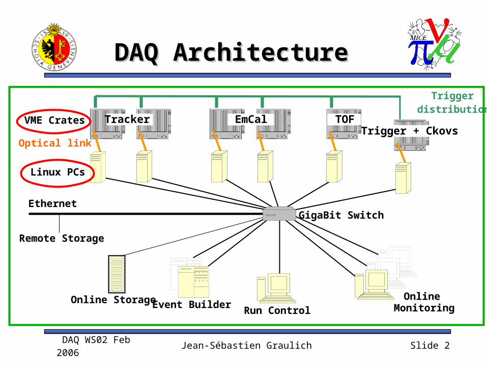
DAQ ArchitectureDAQ Architecture
Trigger distribution
Optical link
Online Monitoring
Tracker EmCal TOFTrigger + Ckovs
Ethernet
Linux PCs
GigaBit Switch
Run ControlEvent BuilderOnline Storage
VME Crates
Remote Storage

DAQ WS02 Feb 2006
Jean-Sébastien Graulich Slide 3
Hardware Hardware ConsequencesConsequences
PCs are sitting in the MICE LCRPCs are sitting in the MICE LCR -> VME crates are also sitting in the -> VME crates are also sitting in the
MICE LCRMICE LCRCable transmission of Analog Signal or Digital Signal

MICE layout
Drawing by Tony Jones

DAQ WS02 Feb 2006
Jean-Sébastien Graulich Slide 5
Tracker Tracker
Sensors: VLPCSensors: VLPC Front End Electronics (without AFE-Front End Electronics (without AFE-
t):t): Analog to Digital: AFE II boards sitting on the
cryo-cooler Digital Data Buffer: VLSB (512 ch/module, 4
modules/cryo-cooler) Number of ChannelsNumber of Channels
2 x 4096 ADC
DAQ WS02 Feb 2006
Jean-Sébastien Graulich Slide 6
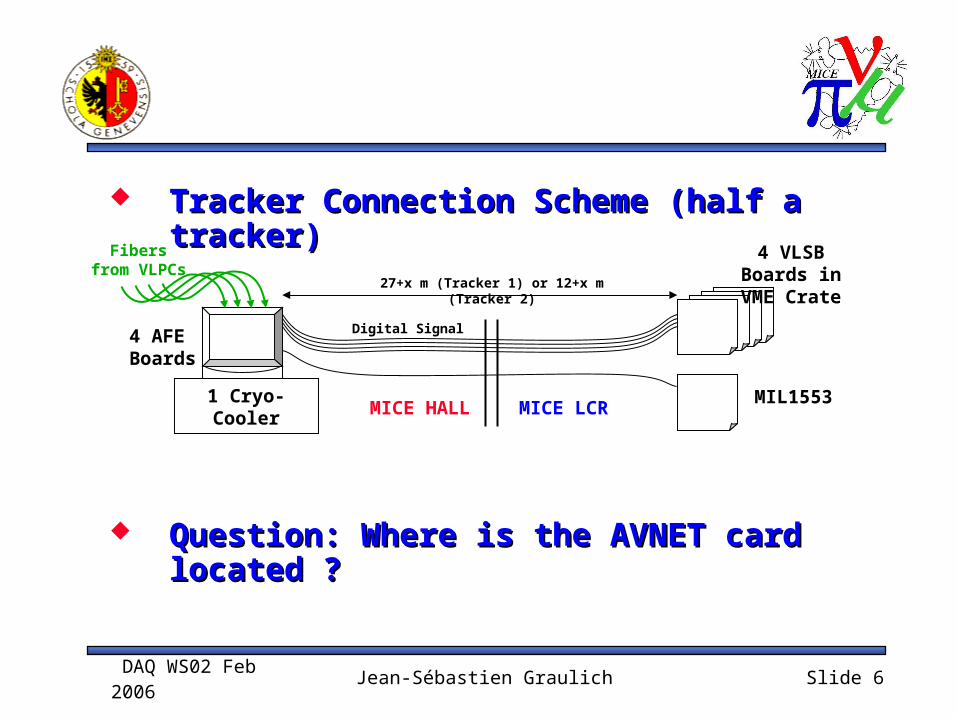
Tracker Connection Scheme (half a Tracker Connection Scheme (half a tracker)tracker)
4 VLSB Boards in VME Crate
MICE LCRMICE HALL1 Cryo-Cooler
4 AFE Boards
Fibers from VLPCs
Digital Signal
27+x m (Tracker 1) or 12+x m (Tracker 2)
Question: Where is the AVNET card Question: Where is the AVNET card located ?located ?
MIL1553
DAQ WS02 Feb 2006
Jean-Sébastien Graulich Slide 7
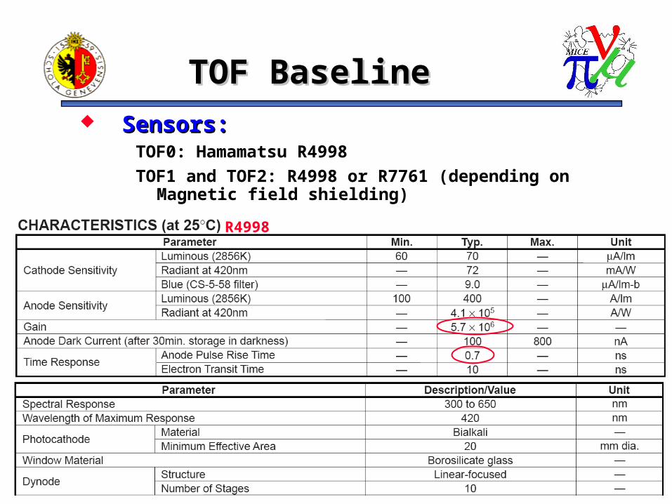
TOF Baseline TOF Baseline Sensors: Sensors:
TOF0: Hamamatsu R4998TOF1 and TOF2: R4998 or R7761 (depending on
Magnetic field shielding)
R4998
DAQ WS02 Feb 2006
Jean-Sébastien Graulich Slide 8
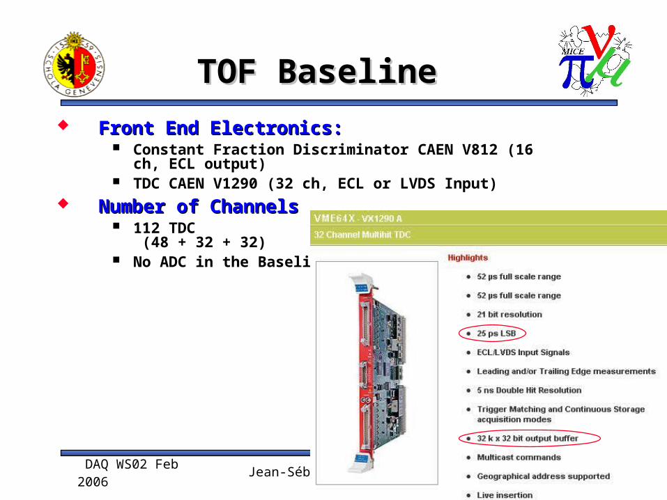
TOF BaselineTOF Baseline Front End Electronics:Front End Electronics:
Constant Fraction Discriminator CAEN V812 (16 ch, ECL output)
TDC CAEN V1290 (32 ch, ECL or LVDS Input) Number of ChannelsNumber of Channels
112 TDC (48 + 32 + 32)
No ADC in the Baseline

DAQ WS02 Feb 2006
Jean-Sébastien Graulich Slide 9
TOF BaselineTOF Baseline
TOF Connection Scheme (1 Station)TOF Connection Scheme (1 Station)
Question: Is CFD going to be precise enough ?Question: Is CFD going to be precise enough ? See other options
3 CFD in VME Crate
BNC Cable (RG213) TriggerLogic
MICE LCRMICE HALL
48 PMTs
1.5 TDC in VMESHV Cable
HV Power Supply
30+x m (TOF 0) or 27+x m (TOF 1) or 12+x m (TOF 2)

DAQ WS02 Feb 2006
Jean-Sébastien Graulich Slide 10
Timing is affected by the signal amplitudeTiming is affected by the signal amplitude
2 Usual Solutions: 2 Usual Solutions: Use Constant Fraction Discriminator (CFD) Measure amplitude and correct
TOF OptionsTOF Options
TimeWalk
Time over threshold
Thresh.
Tim
e W
alk
Co
rre
ctio
nExample from Harp

DAQ WS02 Feb 2006
Jean-Sébastien Graulich Slide 11
TOF OptionsTOF Options
Option 1. Constant Fraction Discriminator (CFD)Option 1. Constant Fraction Discriminator (CFD)The time walk is corrected automatically in the discriminator
Threshold value depends on the amplitude
Advantage: Advantage: Easy CablingEasy Cabling and and No ADCNo ADC
DrawbackDrawback No information at all on the charge (Energy
Deposit) Cost: TDC +Cost: TDC + ~ 125 EUR/ch (CFD)~ 125 EUR/ch (CFD)
PMT CFDBNC Cable
TDC
Trigger Logic
DAQ WS02 Feb 2006
Jean-Sébastien Graulich Slide 12
TOF OptionsTOF Options
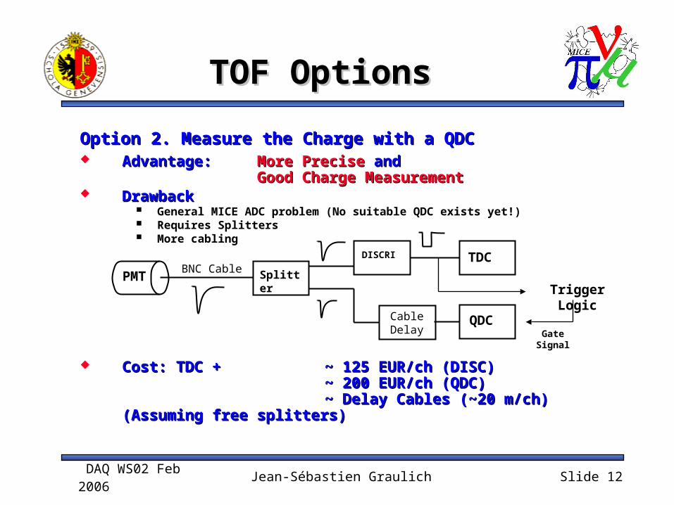
Option 2. Measure the Charge with a QDCOption 2. Measure the Charge with a QDC Advantage: Advantage: More PreciseMore Precise and and
Good Charge MeasurementGood Charge Measurement DrawbackDrawback
General MICE ADC problem (No suitable QDC exists yet!) Requires Splitters More cabling
Cost: TDC +Cost: TDC + ~ 125 EUR/ch (DISC)~ 125 EUR/ch (DISC) ~ 200 EUR/ch (QDC)~ 200 EUR/ch (QDC)
~ Delay Cables (~20 m/ch)~ Delay Cables (~20 m/ch)(Assuming free splitters)(Assuming free splitters)
Gate Signal
PMT
DISCRI
CableDelay
TDC
Trigger LogicSplitter
QDC
BNC Cable
DAQ WS02 Feb 2006
Jean-Sébastien Graulich Slide 13
TOF OptionsTOF Options
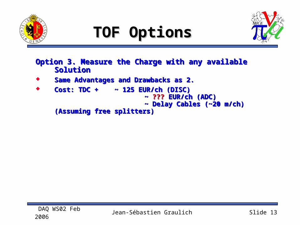
Option 3. Measure the Charge with any available Option 3. Measure the Charge with any available SolutionSolution
Same Advantages and Drawbacks as 2.Same Advantages and Drawbacks as 2. Cost: TDC +Cost: TDC + ~ 125 EUR/ch (DISC)~ 125 EUR/ch (DISC)
~ ~ ?????? EUR/ch (ADC) EUR/ch (ADC)~ Delay Cables (~20 m/ch)~ Delay Cables (~20 m/ch)
(Assuming free splitters)(Assuming free splitters)

DAQ WS02 Feb 2006
Jean-Sébastien Graulich Slide 14
TOF OptionsTOF Options
Option 4. Measure the Charge with Time Over Threshold Option 4. Measure the Charge with Time Over Threshold PrinciplePrinciple
Advantage: Advantage: Easy CablingEasy Cabling and and Charge Measurement Charge Measurement (not linear though)(not linear though)
Good PrecisionGood Precision for Time Walk Correction for Time Walk Correction
NINO = ASIC developed by CERN/MIC for Alice TOFNINO = ASIC developed by CERN/MIC for Alice TOF Discriminator with ToT “proportional” to the Charge (at low Discriminator with ToT “proportional” to the Charge (at low amplitude)amplitude) Proven technique, providing 50 ps resolution Proven technique, providing 50 ps resolution (IEE TNS Vol 51-5 (2004) 1974-(IEE TNS Vol 51-5 (2004) 1974-1978)1978)
Very Cheap: 2 EUR/chVery Cheap: 2 EUR/ch
Drawback Drawback Requires Board development !
Cost: TDC +Cost: TDC + Discri. board production (~50 EUR/ch) Discri. board production (~50 EUR/ch)
PMT NINO TDC
Trigger LogicWidth ~Charge
Rising edge + Trailing edge Time Measurement

DAQ WS02 Feb 2006
Jean-Sébastien Graulich Slide 15
EmCal Baseline EmCal Baseline Sensors: Sensors:
Hamamatsu R1355 (100 in hand, Ludovico is trying to find the other 140…)
Modified for differential output (100 Ohms)

DAQ WS02 Feb 2006
Jean-Sébastien Graulich Slide 16
EmCAl BaselineEmCAl Baseline
Front End Electronics:Front End Electronics: Splitters Discriminators TDC: CAEN V1190 (128 ch, ECL or LVDS input) ADC: No Baseline defined yet
Number of ChannelsNumber of Channels 240 ADC 120 TDC in the BaselineTime information is useful for
Hit Position information in the direction // to the slab Suppression of muon decay background (the muons
are stopped in the EmCal and ready to decay when the next muon arrives, disturbing PID)
-> My personal feeling: TDC needed for all the channels

DAQ WS02 Feb 2006
Jean-Sébastien Graulich Slide 17
EmCal BaselineEmCal Baseline
EmCal Connection Scheme (Half EmCal)EmCal Connection Scheme (Half EmCal)
Twisted Pair Cable
MICE LCRMICE HALL
120 PMTs Splitter
SHV Cable
HV Power Supply
12+x m
4 Discriin VME
Charge measurement
1 TDC in VME
Transformer
Delay

DAQ WS02 Feb 2006
Jean-Sébastien Graulich Slide 18
EmCal OptionsEmCal Options
TransformerTransformer Needed to adapt the differential output of the
PMt (twisted pair, 100 Ohm) to the Coaxial (Lemo, 50 Ohm) of the Splitter.
SplitterSplitter It is possible to reuse active splitters
developed in Sofia for HARP. 200 channels available
If we have enough charge, the transformer can also be made as a passive splitter with 1 differential input and two coaxial ouputs.
DAQ WS02 Feb 2006
Jean-Sébastien Graulich Slide 19
EmCal Charge Measurement EmCal Charge Measurement OptionsOptions
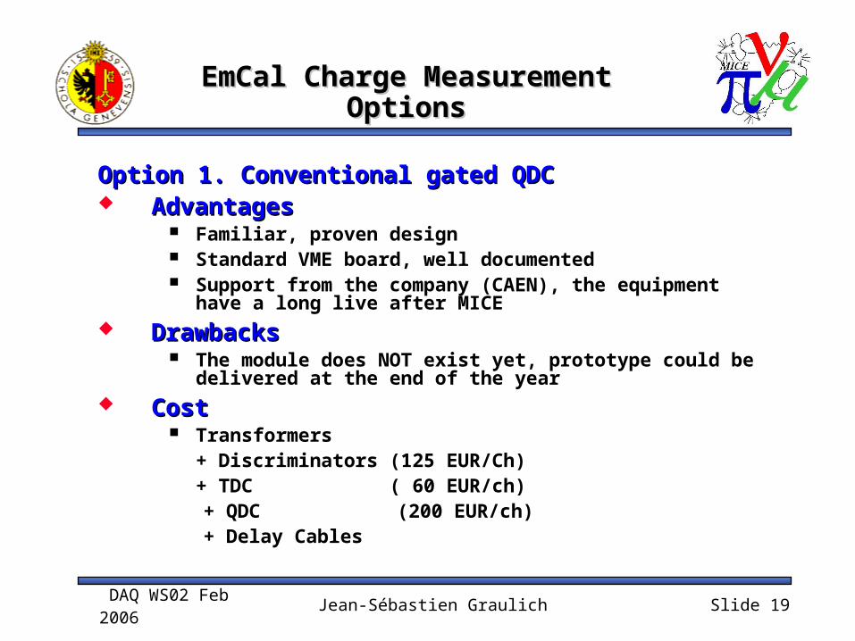
Option 1. Conventional gated QDCOption 1. Conventional gated QDC AdvantagesAdvantages
Familiar, proven design Standard VME board, well documented Support from the company (CAEN), the equipment
have a long live after MICE DrawbacksDrawbacks
The module does NOT exist yet, prototype could be delivered at the end of the year
CostCost Transformers
+ Discriminators (125 EUR/Ch)+ TDC ( 60 EUR/ch)
+ QDC (200 EUR/ch) + Delay Cables

DAQ WS02 Feb 2006
Jean-Sébastien Graulich Slide 20
EmCal Charge Measurement EmCal Charge Measurement OptionsOptions
Option 2. QIE (TeV IPM)Option 2. QIE (TeV IPM) AdvantagesAdvantages
Probably no need for delay cable The transformer can probably be included in the
front end board (if we re-layout the board…) Could be used for TOF (or CKOV) charge
measurement DrawbacksDrawbacks
Development Risk Not VME readout, makes the DAQ more tricky.
Probably OK but who knows… CostCost
+ QIE FEB (??? EUR/ch)+ PC BC (??? EUR/ch)+ Discriminators (125 EUR/Ch)+ TDC ( 60 EUR/ch)

DAQ WS02 Feb 2006
Jean-Sébastien Graulich Slide 21
EmCal Charge Measurement EmCal Charge Measurement OptionsOptions
Option 3. 200 MHz Flash ADCs Option 3. 200 MHz Flash ADCs
AdvantagesAdvantages No Splitter, no delay, no discri, no TDC ! Cabling very easy Equipment has a long after MICE life
DrawbacksDrawbacks Transformer -> Shaper Time resolution ?
CostCost Flash ADC (450 EUR/ch) + Shaper ( ??? EUR/ch) + VME Crate (6 kEUR)
2 ns rise time
ShaperVthr
tthr >30 ns rise time
If we can fit the rising edge, time resolution can be much higher than the 5 ns of the sampling rate.

DAQ WS02 Feb 2006
Jean-Sébastien Graulich Slide 22
Readout Trigger Readout Trigger BaselineBaseline
6 Event Types:6 Event Types: Normal Event (RF ON or RF OFF) Start of Spill
make sure the DAQ is ready for Normal Event End of Spill
should Contain the relevant MCM data Empty Event (Pedestals) Pulser Events Cosmic/Source Events
1 trigger receiver input per Event Type1 trigger receiver input per Event Type 1 trigger receiver output per Event Type 1 trigger receiver output per Event Type
(busy) + 1 common(busy) + 1 common Trigger receiver is a simple VME IO Register Trigger receiver is a simple VME IO Register
(4 kEUR/Unit)(4 kEUR/Unit)

DAQ WS02 Feb 2006
Jean-Sébastien Graulich Slide 23
Particle Trigger Particle Trigger BaselineBaseline
3 Particle Trigger conditions for Normal Events3 Particle Trigger conditions for Normal Events Beam: Burst x TOF0
Timing given by TOF0
Upstream: Beam x TOF1 Timing given by TOF1
Traversing: Upstream x TOF2 Timing given by Upstream
TOFn is defined by a twofold coincidence of the OR of the 12 (8) slabs of a single layer
Should be possible to add Traversing Muon, using Should be possible to add Traversing Muon, using EmCal informationEmCal information
If it’s really only these 4 conditions, there is no need If it’s really only these 4 conditions, there is no need for PLU. One simple I/O register is enoughfor PLU. One simple I/O register is enough
Option: CMAC PLU (available in Geneva). Requires CAMAC-VME or CMAC PCi Interface
For Empty and Pulser Events, the particle trigger is For Empty and Pulser Events, the particle trigger is generated by the DAQ systemgenerated by the DAQ system
For Cosmic Events, the particle trigger is set up locally For Cosmic Events, the particle trigger is set up locally by the subsystem who wants it by the subsystem who wants it

DAQ WS02 Feb 2006
Jean-Sébastien Graulich Slide 24
SummarySummary
Tracker Baseline has to be updated Tracker Baseline has to be updated for AFEtfor AFEt
TOF Baseline is well defined and TOF Baseline is well defined and several options will be testedseveral options will be tested
EmCal Baseline is not clear (Charge EmCal Baseline is not clear (Charge measurement)measurement)
Trigger Baseline is well defined, no Trigger Baseline is well defined, no problem expected thereproblem expected there


![03d ZXG10 B8018 Hardware Architecture[1]](https://static.fdocuments.us/doc/165x107/577cc2ad1a28aba711945a53/03d-zxg10-b8018-hardware-architecture1.jpg)


