DBL-PBL manual rev 1.1 - Cole-Parmer · 5.3 External Power Supply / Charger (PBL Only) ..... 19 5.4...
28
Nova-Strobe DBL and Nova-Strobe PBL Deluxe and Phaser LED Stroboscopes MONARCH INSTRUMENT Instruction Manual 15 Columbia Drive Amherst, NH 03031 USA Phone: (603) 883-3390 Fax: (603) 886-3300 E-mail: [email protected] Website: www.monarchinstrument.com
Transcript of DBL-PBL manual rev 1.1 - Cole-Parmer · 5.3 External Power Supply / Charger (PBL Only) ..... 19 5.4...

Nova-Strobe DBL
and
Nova-Strobe PBLDeluxe and Phaser LED Stroboscopes
MONARCH INSTRUMENT
Instruction Manual
15 Columbia Drive
Amherst, NH 03031 USA
Phone: (603) 883-3390
Fax: (603) 886-3300
E-mail: [email protected]
Website: www.monarchinstrument.com

Safeguards and Precautions
1. Read and follow all instructions in this manual carefully, and retain
this manual for future reference.
2. Do not use this instrument in any manner inconsistent with these
operating instructions or under any conditions that exceed the
environmental specifi cations stated.
3. Certain strobe frequencies can trigger epileptic seizures in those
prone to that type of attack.
4. Users should not stare directly at the light source.
5. Prolonged exposure to the light can cause headaches in some
people.
6. Objects viewed with this product may appear to be stationary when
in fact they are moving at high speeds. Always keep a safe distance
from moving machinery and do no touch the target.
7. There are no user serviceable parts in this instrument. Refer service
to a qualifi ed technician.
8. Do not allow liquids or metallic objects to enter the ventilation holes
on the stroboscope as this may cause permanent damage and void
the warranty.
9. Do not allow cables extending from unit to come into contact with
rotating machinery, as serious damage to the equipment, or severe
personal injury or death may occur as a result.
10. This instrument may not be safe for use in certain hazardous
environments, and serious personal injury or death could occur
as a result of improper use. Please refer to your facility’s safety
program for proper precautions.

TABLE OF CONTENTSTABLE OF CONTENTS
1.0 OVERVIEW ..............................................................................1
1.1 Modes of Operation ...........................................................1 1.1.1 Internal Mode .................................................................. 2
1.1.2 External Mode ................................................................. 2
1.1.3 Charging Mode ............................................................... 2
1.2 Brightness ..........................................................................31.2.1 Degree of Rotation Adjustment..................................... 4
1.2.2 Pulse Duration Adjustment ........................................... 4
2.0 PREPARATION FOR USE ......................................................52.1 Power ..................................................................................5
2.2 Input / Output Connections ...............................................6
11. Nova-Strobe LED units contain Nickel Metal Hydride batteries which
must be disposed of in accordance with Federal, State, & Local
Regulations. Do not incinerate. Batteries should be shipped to a
reclamation facility for recovery of the metal and plastic components
as the proper method of waste management. Contact distributor
for appropriate product return procedures.
In order to comply with EU Directive 2002/96/EC on Waste
Electrical and Electronic Equipment (WEEE): This product
may contain material which could be hazardous to human health
and the environment. DO NOT DISPOSE of this product as
unsorted municipal waste. This product needs to be RECYCLED
in accordance with local regulations, contact your local authorities for more
information. This product may be returnable to your distributor for recycling -
contact the distributor for details.
Monarch Instrument’s Limited Warranty applies. See www.
monarchinstrument.com for details.
Warranty Registration and Extended Warranty coverage available online
at www.monarchinstrument.com.

3.0 LED STROBE OPERATION ....................................................7
3.1 Adjusting the Flash Rate - RPM ...................................73.1.1 Using the Knob ............................................................... 7
3.1.2 Using the Keypad ........................................................... 7
3.1.3 Decade Adjustment ........................................................ 8
3.1.4 Multiply or Divide By 2 ................................................... 8
3.1.5 Fixed Increment N Adjustment...................................... 9
3.2 Adjusting the Flash Duration (Brightness) .................93.2.1 Flash Duration - Degrees ............................................... 9
3.2.2 Flash Duration - Microseconds ................................... 10
3.3 Display Units ...............................................................10
3.4 Tachometer Mode ........................................................10
3.5 Mode Selection ............................................................ 11
3.6 Memory ........................................................................ 11
3.7 Phase Delay .................................................................12
3.7.1 Internal Phase Delay .................................................... 12
3.7.2 External Delay (PBL Model ONLY) .............................. 12
3.8 Menu .............................................................................13
3.8.1 Decimal Places ............................................................. 13
3.8.2 Backlight ....................................................................... 14
3.8.3 Input Pulse Edge .......................................................... 14
3.8.4 Output Pulse Polarity ................................................... 14
3.8.5 Blanking ........................................................................ 15
4.0 USING THE STROBOSCOPE TO MEASURE RPM ............15
5.0 BATTERIES ...........................................................................17
5.1 Low Battery Indication ................................................18
5.2 Charging the Batteries ................................................18
5.3 External Power Supply / Charger (PBL Only) ...........19
5.4 Stroboscope Disposal ................................................19
6.0 SPECIFICATIONS .................................................................20
7.0 OPTIONS AND ACCESSORIES / SENSORS ......................22

1
Figure 1 LED Strobe
Control Panel
1.0 OVERVIEW
The Nova-Strobe Deluxe DBL and Phaser PBL LED (Light Emitting Diode)
are rugged portable battery powered LED Stroboscopes used for inspection
and to stop motion to determine the speed of rotating objects. The units have
a pistol grip with lockable trigger switch and wrist strap for comfortable
hand held operation or they may be mounted on a tripod using the integral
¼ -20 UNC thread at the base of the handle. Although the DBL and PBL
are similar, the PBL has the additional ability to phase shift the image with
respect to an external signal and can animate the image in slow motion
rotation for inspection purposes. The PBL can also run continuously from
an external power supply.
The Deluxe and Phaser LED
Strobes have a two line backlit
alpha-numeric liquid crystal
display (LCD) and a 12 key keypad
enables the user to simply enter
data and control the operation
of the unit. The keys have dual
functions – the primary function is
shown by the black printing on the
blue background on the top half of
the key. The secondary function
is as a numeric keypad and the
numerics are shown against a
white background on the bottom
half of the key – 0 to 9, period and ENTER. The LCD display has several
icons which will be explained later in this manual.
1.1 Modes of Operation
The stroboscope has two basic modes of operation – INTERNAL and
EXTERNAL.

2
1.1.1 Internal Mode
The strobe is in the Internal Mode when nothing is plugged into
the input jack or when manually set using the INPUT button. In
the internal mode the strobe generates its own timing signals and
the users can enter the fl ash rate using several different methods
– see Section 3.1.
1.1.2 External Mode
In the External Input Mode the user can’t make any fl ash rate
adjustments with the knob. The fl ash rate is a function of the input
signal. This mode is used to synchronize the fl ash to an external
event (for example, from an optical sensor) to stop or freeze motion.
The fl ash will be triggered on the rising or falling edge (menu
selectable) of the external input pulse. The strobe is in the External
Input Mode whenever there is a plug in the input jack. When the
strobe is in the External Input Mode, EXT will be displayed.
When an external input is applied to the unit and the strobe is put
in the Tachometer Mode, the unit will read the signal from the
external input (sensor) and display the reading on the LCD display
without fl ashing the lamp. The strobe will not fl ash in the Tach
(Tachometer) Mode.
1.1.3 Charging Mode
The Charging Mode is when the strobe has the battery recharger
plugged into it. The strobe will continuously display the state of
the battery charge while being recharged.

3
1.2 Brightness
GLOSSARY:
LED – Light Emitting Diode
msec – millisecond = 1/1,000 of a second
µsec – microsecond = 1/1,000,000 of a second
° = degree. One rotation = 360°
The strobe’s brightness depends on how wide the LED fl ash pulse is;
the wider the pulse, the brighter the visual output from the LEDs. Since
the strobe is primarily used on reciprocating or rotating targets there is a
downside to the wider fl ashes. All strobes work by giving short bursts of
light (the pulse width) at a rapid repetition rate (the fl ash rate). Strobes
rely on the persistence of the human eye (the ability to remember and
image) and its response to bright light to give an apparent stop motion
image. Imagine a shaft rotating at 6000 RPM or one rotation every 1/100
of a second (10 msec). If the strobe fl ashes once every 10 msec for a brief
moment, the user sees the fl ash at the same spot in the rotation of the
shaft and the persistence of the eye remembers this until the next fl ash
making the shaft appeared to be stopped. As the target is rotating there
is some movement evident during the strobe fl ash. The longer the fl ash
duration, the more obvious the rotation is and this increases the blur.
This blur can be calculated – if the shaft takes 10 msec to complete
one revolution and the strobe fl ash duration is 100 µsec (1/100 of a
millisecond), the shaft will turn:
(fl ash duration/time per rotation) x 360°, which is (.0001/.01) x 360 = 3.6°.
So you will see the shaft move 3.6°. As the fl ash pulse widens you will
see greater degrees of rotation which results in more blur and a brighter
perceived illumination (the LEDs are on longer so the average light the
eyes see is greater). The trade-off is blur versus brightness. One also has

4
to take into account tangential velocity (rotational speed) – the further
away the rotating point is from the center axis the faster the tangential
velocity and the worse the blur appears to be – it is always the same
number of degrees of rotation but the physical length of the blur gets
bigger as the point moves faster. The strobe adjusts the width of the pulse
automatically to keep the degree of rotation visible constant.
There are two methods of adjusting the fl ash pulse width and hence the
brightness and consequently the blur.
1.2.1 Degree of Rotation Adjustment
The fi rst method is to adjust the fl ash pulse width for degree of
rotation visible (blur). The user can set this from 0.2 to 14 degrees
out of 360. The higher the setting the brighter the strobe appears to
be but the more blurred the target is. Optimal setting to stop motion
is 1.8 to 3.6°. The number of degrees is a proportional amount
and remains constant as the fl ash rate increases or decreases. The
strobe automatically calculates how wide the pulse width should
be at different fl ash rates to keep the blur constant – the faster the
fl ash rate the narrower the pulse width. The pulse width equals:
(setting in degrees/360) x (1/fl ash rate in Hz).
Thus the blur remains constant no matter what the fl ash rate*.
1.2.2 Pulse Duration Adjustment
The second method is to adjust the fl ash pulse width to a fi xed
number of microseconds. Here the user sets the fl ash pulse width
in microseconds not degrees. As the fl ash rate increases the pulse
width stays the same and the image will get brighter and more
blurred as the fl ash width remains constant*. The degree of rotation
visible changes to keep the pulse width of the fl ash constant*.
*Note: There are two limits maintained by the strobe – the pulse
can never be greater than 3000 µs nor can it exceed 14° of rotation.

5
The strobe automatically adjusts these values as the fl ash rate is
increased or decreased to maintain these limits at all times. For
example - at a fl ash rate of 600 fl ashes per minute 14° of blur
represents a fl ash pulse width of 3800 µsec. The Strobe will limit
this value to 3000 µsec or 10.8° of rotation (blur).
2.0 PREPARATION FOR USE
The Stroboscope may be hand held or mounted on a tripod or other user
supplied bracket using the ¼-20 UNC bushing at the base of the handle.
2.1 Power
The LED Strobe is battery powered and has internal rechargeable
batteries. The unit should be charged before use (see Section 5.0).
The actual operating time of the stroboscope depends on the fl ash pulse
width. Narrower fl ash widths increase the operating time. Note that the
DBL strobe will not operate from the recharger supplied with the unit.
The PBL will run continuously from the supplied AC powered charger
(PSC-PBXU).
To turn on the stroboscope, depress and hold the trigger. The trigger
may be locked in position using the side locking button. To lock the
stroboscope on, depress the trigger as far as it will go and then press
the locking button. Once the locking button is set you may release the
trigger and the trigger will be held in place. To unlock the stroboscope,
simply depress the trigger and then release.
NOTE: Unit must power down completely (OFF will be displayed
and then disappear) before unit will power on again. This is
normal operation. Wait 2 seconds before turning the unit back
on again.

6
2.2 Input / Output Connections
The strobe has input and output jacks on the left side of the stroboscope.
These can be used for external triggering or synchronization (daisy-
chaining two or more strobes). These jacks accept 1/8” (3.5mm) phone
plugs (input - stereo, output - mono). The input and output signals are
TTL compatible. See Figures 2 and 3 for connector connection detail.
The input jack (p pointing into socket) enables an external signal to
trigger the strobe. Inserting a plug into the input jack will automatically
put the strobe into the external mode. The INPUT button can be used
to toggle between External Input Mode and Internal Mode. When the
plug is removed, the strobe will be put back into the Internal Mode.
Signal Input
+6V Out to
Sensor
Common
(GND)
Common
(GND)
+6V Out to
Sensor
Signal Input
Figure 2 Input Connector Detail (Stereo plug)
Pulse Output
from Strobe
Common
(GND)
Common
(GND)
Pulse Output
from Strobe
Figure 3 Output Connector Detail (Mono plug)

7
The polarity of the input pulse can be set in the MENU options. In the
external mode the knob cannot be used to change the fl ash rate.
With no external input, the output jack (q pointing away from socket)
provides a TTL compatible pulse from the strobe’s internal oscillator.
If an external input is applied, the output pulse is in sync with the input
pulse. This output pulse may be used to trigger a second stroboscope
synchronously to illuminate larger areas. Many strobes can be “daisy
chained”. The output jack of one strobe is connected to the input jack of
the next strobe causing all the strobes to fl ash together and be controlled
by the fi rst strobe in the chain. The polarity of the output pulse can be
set in the MENU options.
3.0 LED STROBE OPERATION
3.1 Adjusting the Flash Rate - RPM
There are several ways to adjust the fl ash rate of the Strobe:
3.1.1 Using the Knob
The fl ash rate can be adjusted by turning the knob on the side of the
unit – counter clockwise to increase the fl ash rate and clockwise
to decrease the fl ash rate. The knob is rate sensitive, the faster you
turn the knob the greater the change in fl ash rate. The smallest
adjustment is to add or subtract one from the least signifi cant (right
most) digit on the display.
3.1.2 Using the Keypad
It is possible to enter the required fl ash rate as a number
by entering the value using the keypad as you would
with a calculator. Press the NUMber key shown right
followed by the numeric keys representing the fl ash
rate (eg 1234), using the secondary key functions –
numbers 0 to 9 and the period, then press the ENTER

8
button. Note: The system will round the display to the nearest least
signifi cant digit displayed. If the display has no decimal places and
you enter 1234.6 the display will show 1235 and the strobe will
fl ash at 1234.6 fl ashes per minute.
3.1.3 Decade Adjustment
The fl ash rate can be adjusted in decade steps eg: 1, 10,
100 etc. by pressing the � button shown right. This
will start a digit on the display blinking. If the knob is
turned this digit will increment or decrement with rollover and roll
under features. Each time the � button is pressed the blinking digit
moves one position to the right, the decade decreases by 10 until
the digits stop blinking. Pressing the � button again will cause the
left most digit to start blinking.
To exit the decade adjustment mode while a digit is blinking press
any key other than the � button.
3.1.4 Multiply or Divide By 2
The strobe fl ash rate can be instantly doubled (x2) or
halved (÷2) by pressing the x2 and ÷2 buttons shown
right. This is useful in determining actual rotational
speed. Refer to the section on speed measurement –
Section 4.0. Note that if doubling or halving the fl ash
rate will cause the strobe to exceed its capability, the
display will show OVER or UNDER respectively and the fl ash
rate will remain at the current fl ash value.
�
������� > > > > > > > >

9
3.1.5 Fixed Increment N Adjustment
The strobe fl ash rate can be incremented or decremented
in fi xed increments. To do this, adjust the fl ash rate to
the required adjustment value, say 300, which we will
refer to as N. Then press the ±N button shown right (Note: – N is
the displayed value at the time the button is pressed). The display
will show ALT in the bottom left hand corner which indicates
the knob is in the ALTernate function mode. Turning the knob
counterclockwise will increase the fl ash rate by N (300 in this
example) for each click or turning it clockwise will decrease the
fl ash rate by N. It is not possible to decrement the fl ash rate below
30 FPM.
3.2 Adjusting the Flash Duration (Brightness)
The fl ash duration, the width of the LED fl ash, can be adjusted by the
user to be a preset number of degrees of rotation (DEGS) or a fi xed with
in microseconds (uSEC). The result is a more or less bright image at
the expense of less or more image blur. Read the section on Brightness
- Section 1.2.
3.2.1 Flash Duration - Degrees
To view or adjust the fl ash duration press the BRIGHT
button shown on the right. The display will show the
current fl ash duration in degrees of rotation – note
that there are 360° in a complete rotation. The
degrees shown is the amount of rotation visible
during the fl ash. The higher the degrees the
brighter the image and the more apparent the
blur. Use the knob to increase or decrease the fl ash duration in
degrees of rotation. Adjusting the degrees will cause this to be the
controlling parameter for pulse width. As the fl ash rate increases
or decreases the strobe will adjust the fl ash duration to keep it at
1.2DEGS

10
the preset number of degrees provided this does not exceed the
strobe specifi cations. Press any key other than BRIGHT to exit
or press BRIGHT again to go to MICROSECOND adjustment.
3.2.2 Flash Duration - Microseconds
To view or adjust the fl ash duration in microseconds
press the BRIGHT button again after viewing degrees
or press the BRIGHT button twice from normal
operation. The display will show the current
fl ash duration in microseconds (uSECS) – this
may be calculated from phase degrees set above.
Use the knob to increase or decrease the fl ash
duration in microseconds. Adjusting the microseconds will cause
this to be the controlling parameter for pulse width. As the fl ash
rate increases or decreases the strobe will keep the fl ash duration
at the preset width in microseconds provided this does not exceed
the strobe specifi cations. Press the BRIGHT button to exit the
fl ash duration adjustment.
3.3 Display Units
The display can show the fl ash rate in revolutions per minute
(RPM) or per second (RPS or Hertz). To switch between
display modes press the DISPlay button shown right. The
display units will toggle at each press (RPM < > RPS).
3.4 Tachometer Mode
The stroboscope can be used as a programmable pulse
generator or as a tachometer by pressing the TACH button
shown right. When an external input is supplied to the unit
and the strobe is put in the Tachometer Mode, the unit will read the
signal from the external input (sensor) and display the reading on the
LCD display without fl ashing the lamp. The TACH icon will show on
1234uSECS
11
the display. There is also an ON TARGET INDICATOR shown
right which illuminates when a valid external signal is received.
If there is no external input and the TACH button is pressed
the strobe will stop fl ashing but will still output a pulse at the rate
indicated on the display. This rate may be adjusted as described in
Section 3.1 above.
To exit the Tachometer mode press the TACH button again.
3.5 Mode Selection
The INPUT button, shown right, toggles between the
INTERNAL and EXTERNAL Modes as described in Section
1.1. When in the external mode the display will show EXT
and the stroboscope will only fl ash with an external input. Plugging
in an external source will cause the unit to automatically switch to
the EXTERNAL mode. Removing an external source while in the
EXTERNAL mode will cause the unit to switch to the INTERNAL
mode.
3.6 Memory
The Stroboscope has the ability to save and recall up to 5
values. This is done by pressing the MEMory button shown
right. The fi rst time the button is pressed the display will show
READ, if pressed again it will show SAVE. If the knob is turned while
READ or SAVE is displayed, the display will cycle through memory
locations 1 to 5 (indicated as RM1 to RM 5 where RM is Recall Memory
or SM1 to SM 5 where SM is Save Memory). To actually SAVE or
READ the selected memory location, press the MEM button again.
The ENTER button works as well. The display will show DONE. Note
that the value saved will be the current fl ash rate prior to pressing the
MEM button the fi rst time.

12
3.7 Phase Delay
The DELAY button adjusts the phase shift of the fl ash with
respect to time. There are two modes: INTERNAL and
EXTERNAL (PBL model only).
3.7.1 Internal Phase Delay
Also referred to as JOG. Once the fl ash rate has been adjusted to
give a stopped motion image, the PHASE DELAY button may be
used to increase or decrease the phase of the image with respect
to its original position. Use the PHASE DELAY button to bring a
reference mark, such as a key way, into your line of sight.
To adjust the phase or jog the image, press the DELAY button.
PHASE will be displayed on the bottom line of the LCD display
and the current fl ash rate will be displayed on the top line. Turning
the knob adjusts the phase of the stopped image. It is a relative
adjustment. Press the DELAY button again to exit this mode.
3.7.2 External Delay (PBL Model ONLY)
The DELAY button has no function in External mode on the DBL
model stroboscope.
On the PBL model stroboscope there are three External Delay
Modes: Phase Delay, Time Delay, and Auto (Virtual RPM).
These modes are only active if an external trigger source is plugged
into the unit. The EXTernal icon must appear on the display.
Pressing the DELAY button cycles through the following modes:
In the External Phase Delay mode the fl ash is delayed 0.1 to 359.9
degrees after each external trigger pulse. The display will show
the delay in degrees on the top line and will indicate PHASE on
the lower line. The knob adjusts the amount of delay in degrees,
counterclockwise to increase and clockwise to decrease.

13
In the External Time Delay mode the fl ash is delayed 0.01 to
1000 msec after each external trigger pulse. The display will show
the TIME icon, the delay in milliseconds on the top line and will
indicate MSECS on the lower line. The knob adjusts the amount of
delay in milliseconds, counterclockwise to increase and clockwise
to decrease.
In the Auto (Virtual RPM) mode the fl ash is automatically
delayed in increasing amounts after the external trigger pulse so
that the image appears to rotate at a slow (Virtual) speed, RPM.
The display will show the AUTO icon, the virtual speed in RPM
on the top line and will indicate VRPM (Virtual RPM) on the lower
line. The knob adjusts the virtual speed in RPM, counterclockwise
to increase and clockwise to decrease.
3.8 Menu
The Menu allows settings of basic setup options – displayed
decimal places, backlight on or off, positive or negative edge
for input and output signal and blanking. The menu is entered
by pressing the MENU button and using the knob to scroll through the
menu options as described below. The top display line shows Setup.
To select a menu option, press the MENU button again.
3.8.1 Decimal Places
Sets the number of decimal places shown on the display for
numeric. After pressing the MENU button rotate the knob until the
display bottom line shows DECPT and press the MENU button
again. The top line of the display will show the number of decimal
places (2, 1, none) selected by rotating the knob. Press the MENU
button to select, then any other key to exit. The display will show
DONE and return to the normal readout.

14
3.8.2 Backlight
Enables the display backlight to be turned on or off. After pressing
the MENU button rotate the knob until the display bottom line
shows BLITE and press the MENU button again. The top line
of the display will show Yes or No selected by rotating the knob
counterclockwise (yes) or clockwise (no). The backlight will turn
on and off accordingly. Press the MENU button to select, then
any other key to exit. The display will show DONE and return to
the normal readout.
3.8.3 Input Pulse Edge
Sets the input pulse edge that triggers the stroboscope. After
pressing the MENU button rotate the knob until the display bottom
line showsINPUT and press the MENU button again. The top line
of the display will show the PoS (for positive edge triggered) or
nEg (for negative edge triggered) selected by rotating the knob
counterclockwise (PoS) or clockwise (nEg). Press the MENU
button to select, then any other key to exit. The display will show
DONE and return to the normal readout.
3.8.4 Output Pulse Polarity
Sets the polarity of the output pulse. After pressing the MENU
button rotate the knob until the display bottom line shows OUTPT
(Output) and press the MENU button again. The top line of
the display will show the PoS (for positive edge triggered) or
nEg (for negative edge triggered) selected by rotating the knob
counterclockwise (PoS) or clockwise (nEg). Press the MENU
button to select, then any other key to exit. The display will show
DONE and return to the normal readout.

15
3.8.5 Blanking
Blanking is used to reject the strobe’s own fl ash when using an
external optical sensor and prevent double triggering. After pressing
the MENU button rotate the knob until the display bottom line
shows BLANK and press the MENU button again. The top line
of the display will show Yes or No selected by rotating the knob
counterclockwise (yes) or clockwise (no). Yes enables blanking, no
disables it. Press the MENU button to select, then any other key to
exit. The display will show DONE and return to the normal readout.
4.0 USING THE STROBOSCOPE TO MEASURE
RPM
The primary use for a stroboscope is to stop motion for diagnostic inspection
purposes. However the stroboscope can be used to measure speed (in RPM
/ RPS). In order to do this several factors need to be considered. First, the
object being measured should be visible for all 360° of rotation (e.g. The
end of a shaft). Second, the object should have some unique part on it, like a
bolt, key way or imperfection to use as a reference point. If the object being
viewed is perfectly symmetrical, then the user needs to mark the object with
a piece of tape or paint in a single location to be used as a reference point.
Look only at the reference point.
If the speed of rotation is within the range of the stroboscope, start at a
higher fl ash rate and adjust the fl ash rate down. At some point you will stop
the motion with only a single reference point of the object in view. Note that
at a fl ash rate twice the actual speed of the image you will see two images
(reference points). As you approach the correct speed you may see three,
four or more images at harmonics of the actual speed. The fi rst SINGLE
image you see is the true speed. To confi rm the true speed, note the reading
and adjust the stroboscope to exactly half this reading, or just press the ÷2

16
button. You should again see a single image (which may be phase shifted
with respect to the fi rst image seen).
For example, when viewing a shaft with a single key way you will see one
stationary image of the key way at the actual speed and at 1/2,1/3,1/4, etc, of
the actual speed. You will see 2 images of the key way at 2 times the actual
speed, 3 key way at 3 times, etc. The FPM equals the shafts Revolutions Per
Minute (RPM) at the highest fl ash rate that gives only one stationary image
of the key way.
Example: Object rotating at 3000 RPM
If the speed is outside the full scale range of the stroboscope (500,000
FPM), it can be measured using the method of harmonics and multipoint
calculation. Start at the highest fl ash rate and adjust the fl ash rate down.
You will encounter multiple images so be aware of these. Note the fl ash rate
of the fi rst SINGLE image you encounter, call this speed “A”. Continue
decreasing the fl ash rate until you encounter a second SINGLE image. Note
this speed as “B”. Continue decreasing the speed until you reach a third
SINGLE image at speed “C”.
For a two point calculation the actual speed is given by:
RPM = AB/(A-B)
For a three point calculation:
RPM = 2XY(X+Y)/(X-Y)2 where
X = (A-B) and Y = (B-C)
Stopped Image 1/4 times 1/2 times 1 time 2 times 3 times 4 times
Flash Rate (FPM) 1000 1500 3000 6000 9000 12000
Actual RPM

17
If a Remote Optical Sensor or Magnetic Sensor is used to sense one pulse per
revolution (External mode), the readout will display directly in RPM (FPM)
without any adjustment required.
In instances when you can shut down the device and install a piece of refl ective
tape, then an optical tachometer is easier to use for RPM measurement.
Stroboscopes must be used when you can’t shut down the device. The
human eye is not easily tricked into seeing a stopped image by a stroboscope
when the fl ash rate is slower than 300 FPM. Therefore, stroboscopes are just
about impossible to use below 300 FPM for inspection or to measure RPM.
5.0 BATTERIES
The Nova-Strobe LED is fi tted with rechargeable NiMH (Nickel Metal
Hydride) batteries. These batteries contain fewer toxic metals than NiCd
(Nickel Cadmium) and are currently classifi ed “environmentally friendly”.
They also have 30% more capacity than NiCd batteries of the same size.
Like NiCds, NiMH batteries are prone to self-discharge - 10 to 15% of
charge is lost in the fi rst 24 hours then continues at a rate of 0.5 to 1% per
day. For maximum performance, charge the batteries just prior to use.
When not in use, the batteries should be charged at least every three months,
otherwise the battery capacity will be reduced or the batteries may become
unusable.
Charge the batteries before use and allow 3-5 cycles of charging and
discharging for batteries to reach full capacity.
The enclosure contains control electronics to properly and safely charge
the batteries. Never remove the batteries from the enclosure and attempt to
charge externally. Always use the recharger supplied (PSC-2U for the
DBL and PSC-PBXU for the PBL).

18
5.1 Low Battery Indication
When the batteries are charged, there will be no battery icon indication.
When the batteries are low, the Low Battery icon will blink in the display.
The strobe may still be used for a short time.
Low Battery Icon = Outline blinking (very little time left)
The strobe has a protection feature that prevents the strobe from
operating if the battery voltage is too low. This condition is indicated
by no fl ash and the display shows “LO BAT”. At this time the batteries
must be recharged. Remember to release the trigger switch.
5.2 Charging the Batteries
The unit may be recharged at any time. You do not need to wait until
the low battery condition is indicated.
To charge the strobe with the recharger:
1. Release the trigger so the strobe is off.
2. Plug the recharger cable into the recharger socket (located below
the display panel behind the handle).
3. Plug the recharger into an AC mains wall outlet (115/230 Vac).
CAUTION: Use of rechargers other than the one supplied
(PSC-2U for the DBL and PSC-PBXU for the PBL)
will damage the stroboscope and void the warranty.
When the recharger plug is inserted into the recharger jack, the strobe
will go into the Charging Mode. Make sure the trigger switch is not
depressed. The DBL strobe will not do anything else when charging
(e.g. it will not fl ash and the buttons have no function).
When charging, the strobe will indicate CHRGE in the bottom of the
display. The recharger will fast charge the batteries for about 4-5 hours
and then trickle charge the batteries.

19
Allow the recharger to charge the batteries until the display shows
DONE for peak battery life performance. If the batteries are not charged
to 100% regularly, the batteries will lose capacity.
5.3 External Power Supply/Charger (PBL only)
The PBL will run continuously from the external power supply/charger
(PSC-PBXU) powered by the AC mains (115 – 230 Vac).
To run the PBL from the external power supply/charger
(PSC-PBXU):
1. Plug the recharger cable into the recharger socket (located below
the display panel behind the handle).
2. Plug the recharger into an AC mains wall outlet (115/230 Vac).
3. Press the trigger switch to operate as normal. If the trigger switch
is not pressed, the strobe will start charging. The batteries ARE
NOT charged while the strobe is operational and running off the
power supply/charger.
5.4 Stroboscope Disposal
Prior to disposing of the battery-powered strobe, the user
must remove the Nickel-Metal Hydride batteries. To do this,
remove the LED assembly fi rst. This will expose four (4)
screws that must be removed so the refl ector housing can be
dismantled. There are four (4) additional screws in the case half opposite
the input and output jacks that must be removed. The case halves can
now be separated, exposing the batteries. Remove the cables from the
batteries and place tape over the battery terminals to prevent them from
shorting. The batteries should be sent to a recycling center or returned
to the factory. The rest of the parts may now be disposed of.

20
6.0 SPECIFICATIONS
Internal Mode:
Flash Range 30 - 500,000 FPM (Flashes Per Minute), 0.5 to
8333.33 Hz
Flash Rate Accuracy 0.004% of setting or ± last digit
Flash Rate Resolution 0.01 to 1 FPM (menu selectable), 0.1 FPM resolution
above 9,999.99 FPM, 1 FPM resolution above
99,999.9
Display Update Rate Instantaneous
External Modes:
Flash Range 0 - 500,000 FPM (Flashes Per Minute) 0.5 to
8333.33Hz
Tachometer Mode 5 to 500,000 RPM
Accuracy: ±0.001% of reading or ± last digit
Display Update Rate 0.5 second typical
Trigger to Flash Delay < 5 µsec
External Input TTL Compatible (24V pk max), 500 nanosec min
pulse width, Positive or Negative edge triggered
(menu selectable)
Output Pulse 5V pulse – positive or negative (menu selectable)
One pulse per fl ash
Time Base Ultra Stable Crystal Oscillator
Display LCD display with 6 numeric 0.506 inch [12.85 mm]
high digits and 5 alphanumeric 0.282 inch [7.17
mm] high digits
Indicators Battery level, On Target, ALT, TACH, and EXT
icons
Knob Adjustment Digital Rotary switch with 36 detents per revolution;
velocity sensitive
21
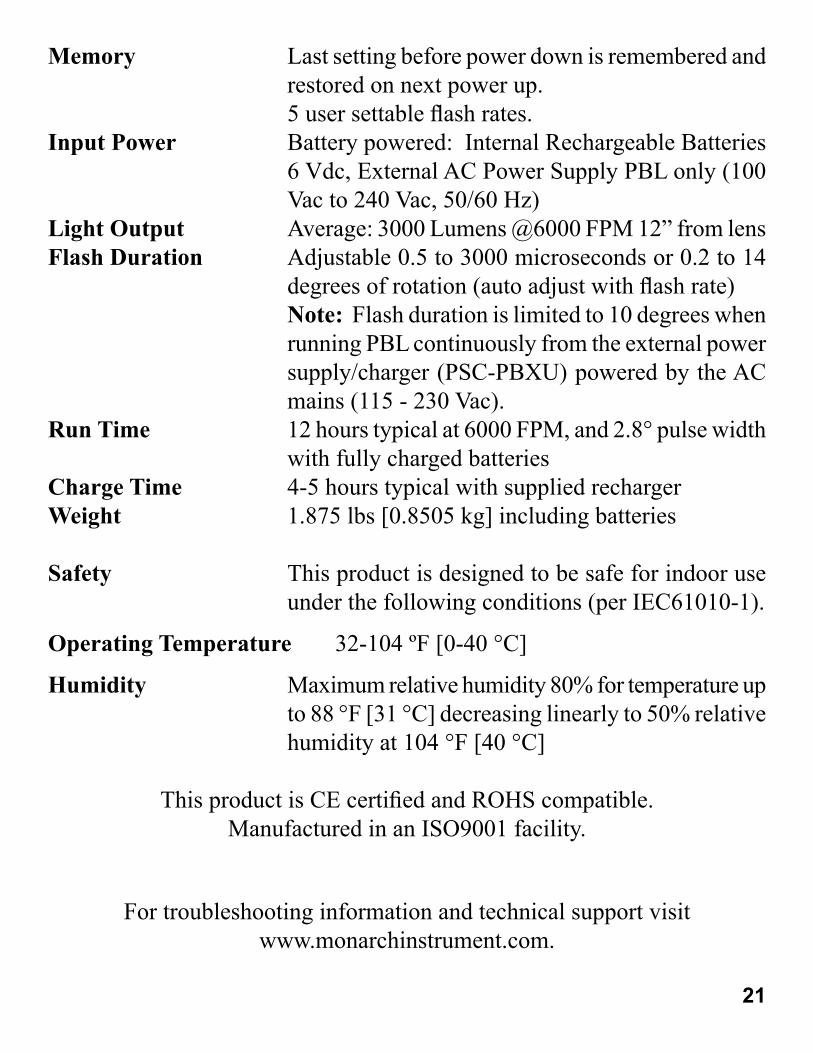
Memory Last setting before power down is remembered and
restored on next power up.
5 user settable fl ash rates.
Input Power Battery powered: Internal Rechargeable Batteries
6 Vdc, External AC Power Supply PBL only (100
Vac to 240 Vac, 50/60 Hz)
Light Output Average: 3000 Lumens @6000 FPM 12” from lens
Flash Duration Adjustable 0.5 to 3000 microseconds or 0.2 to 14
degrees of rotation (auto adjust with fl ash rate)
Note: Flash duration is limited to 10 degrees when
running PBL continuously from the external power
supply/charger (PSC-PBXU) powered by the AC
mains (115 - 230 Vac).
Run Time 12 hours typical at 6000 FPM, and 2.8° pulse width
with fully charged batteries
Charge Time 4-5 hours typical with supplied recharger
Weight 1.875 lbs [0.8505 kg] including batteries
Safety This product is designed to be safe for indoor use
under the following conditions (per IEC61010-1).
Operating Temperature 32-104 ºF [0-40 °C]
Humidity Maximum relative humidity 80% for temperature up
to 88 °F [31 °C] decreasing linearly to 50% relative
humidity at 104 °F [40 °C]
This product is CE certifi ed and ROHS compatible.
Manufactured in an ISO9001 facility.
For troubleshooting information and technical support visit
www.monarchinstrument.com.

7.0 OPTIONS AND ACCESSORIES / SENSORS
PSC-2U Universal Recharger, 115/230 Vac with USA, U.K., AUS, Euro
Adapter Plugs for battery operated Nova-Strobes (included
with DBL)
PSC-PBXU Universal Power Supply/Charger, 115/230 Vac with USA,
U.K., AUS and Euro Adapter Plugs (included with PBL)
CC-7 Latching carrying case for Strobe with provision for
accessories (included with DBL Kit)
CC-12 Deluxe water-tight latching carrying case for Strobe with
provision for accessories (included with PBL Kit)
SPC-1 Splash proof Protective vinyl Cover for Battery Powered
Strobes ONLY
C-4027 Set of mating 1/8 inch (3.5mm) stereo phone plugs (to provide
TTL signal and sensor power)
CA-4044-6 6 foot [1.8 m] Input / Output cable, 1/8 inch [3.5 mm] male
phone plug to male BNC connector
CA-4045-6 6 foot [1.8 m] Input / Output cable, 1/8 inch [3.5 mm] male
phone plug to 1/8 inch [3.5 mm] male phone plug for daisy
chaining strobes together
CAL-N.I.S.T N.I.S.T. Traceable Certifi cate of Calibration / Re-calibration
Protective Rubber cover that fi ts over refl ector housing to protect
strobe
ROLS-P Remote Optical Laser Sensor with 8 foot [2.5 m] cable for
triggering strobe
ROS-P Remote Optical Sensor with 8 foot [2.5 m] cable for triggering
strobe
22
Rubber Cover

ROS-P-25 Remote Optical Sensor with 25 foot [7.6 m] cable for
triggering strobe
IRS-P Infrared Sensor with 8 foot [2.5 m] cable for use without
refl ective target at 0.5 inch [12 mm] gap for triggering strobe
MT-190P Magnetic Trigger Sensor/Amplifi er with 8 foot [2.5 m] cable
for triggering strobe
T-5 Refl ective tape - 5 foot [1.5 m] roll, 0.5 inch [12.7 mm] wide
23

Printed in the U.S.A.
Copyright 2013 Monarch Instrument, all rights reserved
1071-4231-111R-0513