Visualizing Mode shapes with a stroboscope and cola … · PAGE 1 | CRYSTAL INSTRUMENTS Visualizing...
3
VISUALIZING MODE SHAPES WITH A STROBOSCOPE AND COLA OUTPUT CI PRODUCT NOTE | No. 029 WWW.CRYSTALINSTRUMENTS.COM
-
Upload
duongthien -
Category
Documents
-
view
219 -
download
0
Transcript of Visualizing Mode shapes with a stroboscope and cola … · PAGE 1 | CRYSTAL INSTRUMENTS Visualizing...
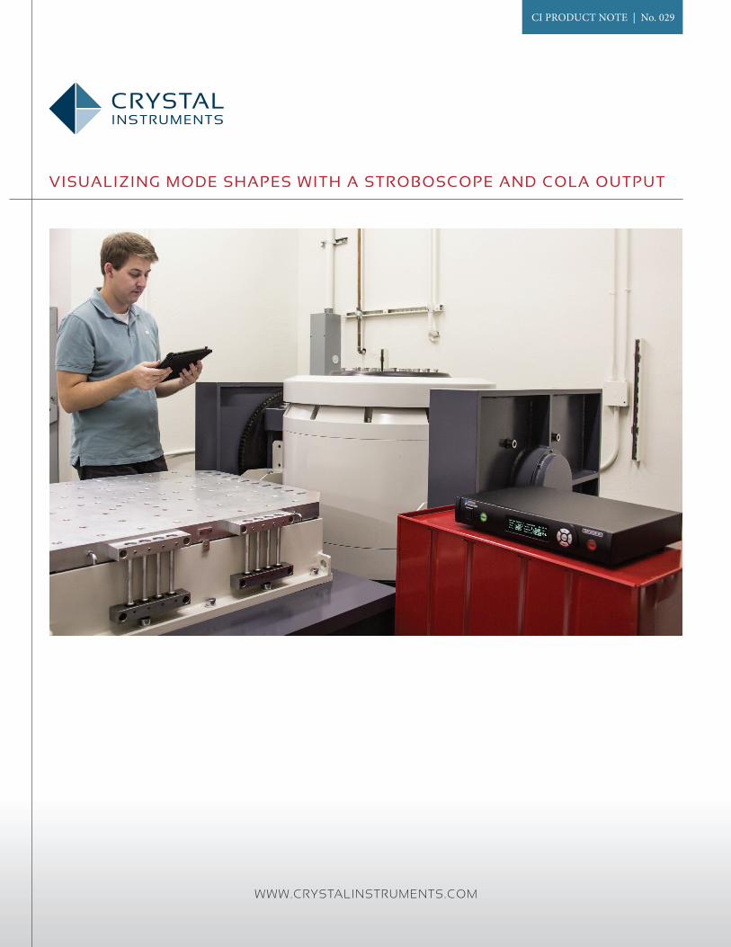
Visualizing Mode shapes with a stroboscope and cola output
CI PRODUCT NOTE | No. 029
WWW.CRYSTALINSTRUMENTS.COM
PAGE 1 | CRYSTAL INSTRUMENTS
Visualizing Mode shapes with a stroboscope and cola output
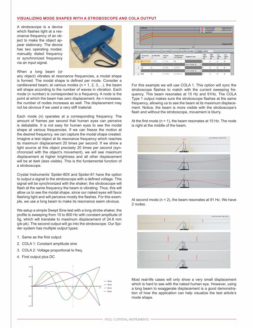
A stroboscope is a device which flashes light at a res-onance frequency of an ob-ject to make the object ap-pear stationary. The device has two operating modes: manually dialed frequency or synchronized frequency via an input signal.
When a long beam (or any object) vibrates at resonance frequencies, a modal shape is formed. The modal shape is defined per mode. Consider a cantilevered beam; at various modes (n = 1, 2, 3,…), the beam will shape according to the number of waves in vibration. Each mode (n number) is corresponded to a frequency. A node is the point at which the beam has zero displacement. As n increases, the number of nodes increases as well. The displacement may not be obvious if we used a very stiff material.
Each mode (n) operates at a corresponding frequency. The amount of frames per second that human eyes can perceive is debatable. It is not easy for human eyes to see the modal shape at various frequencies. If we can freeze the motion at the desired frequency, we can capture the modal shape created. Imagine a test object at its resonance frequency which reaches its maximum displacement 20 times per second. If we shine a light source at this object precisely 20 times per second (syn-chronized with the object’s movement), we will see maximum displacement at higher brightness and all other displacement will be at dark (less visible). This is the fundamental function of a stroboscope.
Crystal Instruments’ Spider-80X and Spider-81 have the option to output a signal to the stroboscope with a defined voltage. This signal will be synchronized with the shaker; the stroboscope will flash at the same frequency the beam is vibrating. Thus, this will allow us to see the modal shape, since our naked eyes will favor flashing light and will perceive mostly the flashes. For this exam-ple, we use a long beam to make its resonance seem obvious.
We setup a simple Swept Sine test with a long strobe shaker, the profile is sweeping from 10 to 800 Hz with constant amplitude of 5g, which will translate to maximum displacement of 24.8 mm (pk-pk). The second output will go into the stroboscope. Our Spi-der system has multiple output types:
1. Same as the first output
2. COLA 1: Constant amplitude sine
3. COLA 2: Voltage proportional to freq.
4. First output plus DC
For this example we will use COLA 1. This option will sync the stroboscope flashes to match with the current sweeping fre-quency. This beam resonates at 15 Hz and 91Hz. The COLA Type 1 output makes sure the stroboscope flashes at the same frequency, allowing us to see the beam at its maximum displace-ment. Notice, the beam is more visible with the stroboscope’s flash and without the stroboscope, movement is blurry.
At the first mode (n = 1), the beam resonates at 15 Hz. The node is right at the middle of the beam.
At second mode (n = 2), the beam resonates at 91 Hz. We have 2 nodes.
Most real-life cases will only show a very small displacement which is hard to see with the naked human eye. However, using a long beam to exaggerate displacement is a good demonstra-tion of how the application can help visualize the test article’s mode shape.

CRYStAL INStRUMENtS2370 OwEN StREEtSANtA CLARA, CA 95054UNItEd StAtES Of AMERICA
Phone: +1 (408) 968 - 8880 | Fax: +1 (408) 834 - 7818 | www.CRYSTaLInSTRUMenTS.CoM | [email protected]
© 2016 Crystal Instruments, All Rights Reserved. 03/2016
Notice: This document is for informational purposes only and does not set forth any warranty, expressed or implied, concerning any equipment, equipment feature, or service offered or to be offered by Crystal Instruments. Crystal Instruments reserves the right to make changes to this document at any time, without notice, and assumes no responsibility for its use. This informational document describes features that may not be currently available. Contact a Crystal Instruments sales representative for information on features and product availability.