Day 1 Item N 4-3--Presentation--Inspectability Of Piping ...
16
9/23/14 1 Review of Piping Inspec0on Programs at the VMT Your Integrity Management Partner From wellhead to burner 6p, Dynamic Risk’s integrity management solu6ons provide you the informa6on to make effec6ve decisions for your en6re asset base. Sept 25, 2014 Confiden6al / Dynamic Risk Project Team Work Product • Project Drivers – APSC assessments iden6fied areas of interest (TAPS 2012 Annual Report Pipeline and VMT Facili:es Corrosion Monitoring) – Includes 36inch relief piping (included in PHMSA Consent Agreement) • Framing Session Highlights – Perform Risk Assessment – Pursue pigging alterna6ve – 36inch relief line plus 48inch A and B header inspec6on is ini6al priority • Recommended strategy for design development – Modify piping to enable inspectability, including ILI tools Alyeska’s Project Z716* VMT Below Ground Crude Oil Piping Summary * This slide is adapted from Alyeska’s presenta6on to Dynamic Risk May 7, 2014.
Transcript of Day 1 Item N 4-3--Presentation--Inspectability Of Piping ...

9/23/14
1
Review of Piping Inspec0on Programs at the VMT
Your Integrity Management Partner From wellhead to burner 6p, Dynamic Risk’s integrity management solu6ons provide you the informa6on to make effec6ve decisions for your en6re asset base.
Sept 25, 2014
Confiden6al / Dynamic Risk Project Team Work Product
• Project Drivers – APSC assessments iden6fied areas of interest (TAPS 2012
Annual Report Pipeline and VMT Facili:es Corrosion Monitoring) – Includes 36-‐inch relief piping (included in PHMSA Consent Agreement)
• Framing Session Highlights – Perform Risk Assessment – Pursue pigging alterna6ve – 36-‐inch relief line plus 48-‐inch A and B header inspec6on is ini6al priority
• Recommended strategy for design development – Modify piping to enable inspectability, including ILI tools
Alyeska’s Project Z716* VMT Below Ground Crude Oil Piping Summary
* This slide is adapted from Alyeska’s presenta6on to Dynamic Risk May 7, 2014.

9/23/14
2
Table 1: Current Inspec6on Ac6vi6es at the VMT Asset Name Ac0vity Status Dynamic Risk Commentary
EMB to East Tank Farm (ETF)(near tanks 1 & 3) Pipe is inspected every 6me it is exposed.
Cathodic protec6on records/ coupon measurements not available. No record of pipe exposure and inspec6on.
• Detailed review of historical coupon and cathodic protec6on records should be conducted.
• Planned for ILI-‐ Specific ILI procedures required.
ETF Headers A & B Annual 3-‐hr sta6c head pressure test. Pipe is inspected every 6me it is exposed.
Cathodic protec6on records/ coupon measurements not available. No record of pipe exposure and inspec6on. Pressure test records not
available.
• Detailed review of historical coupon and cathodic protec6on records should be conducted.
• Planned for ILI-‐ Specific ILI procedures required.
• Pressure tes6ng being performed of pipe body not to recognized industry prac6ce.
ETF to West Metering Building (WMB)
Annual 3-‐hr sta6c head pressure test. Pipe is inspected every 6me it is exposed.
Cathodic protec6on records/ coupon measurements not available. No record of pipe exposure and inspec6on. Pressure test records not
available.
• Detailed review of historical coupon and cathodic protec6on records should be conducted.
• Planned for ILI-‐ Specific ILI procedures required.
• Pressure tes6ng being performed of pipe not to recognized industry prac6ce.
WMB to near shore line Annual 3-‐hr sta6c head pressure test. Pipe is inspected every 6me it is exposed.
Cathodic protec6on records/ coupon measurements not available. No record of pipe exposure and inspec6on. Pressure test records not
available.
• Detailed review of historical coupon and cathodic protec6on records should be conducted.
• Pressure tes6ng being performed of pipe not to recognized industry prac6ce.
• Addi6onal supplementary inspec6ons between all girth welds should be considered.
• Should be considered for ILI program to achieve opera6ng confidence.
Over water piping to Berths 4 & 5
Annual 3-‐hr sta6c head pressure test. By the end of 2014, 100% of the girth welds will be externally inspected, por6ons of insula6on will be permanently removed, and girth welds will be inspected by Visual, UT, EMAT and/or GWT technologies.
Pressure test records not available. External Inspec6on
program is In progress.
• Girth weld inspec6on technology is appropriate and acceptable.
• Pressure tes6ng being performed of pipe is not to recognized industry prac6ce.
• Addi6onal supplementary inspec6ons between all girth welds should be considered.
• Should be considered for ILI program to achieve opera6ng confidence.
VMT Assets Proposed for ILI

9/23/14
3
Alyeska Pipeline Project
Management Process
Identify(FEL 0)
Approve?
STOP
Appraise(FEL 1)
Approve?
Develop(FEL 2)
Approve?
Appraise(FEL 3)
Approve?
Execute
Close
FEL: Front End Loading is a formalized process to develop communicate and reach stakeholder alignment for a definitive project scope to improve the efficiency and reliability of project delivery.
START: Year 0
Year 1
END: Year 2
GATE: An approval process after each FEL step to reduce the number of changes in later project stages.
STOP: Each gate in the process allows for the project to be cancelled or shelved. N
O
NO
NO
NO
Review
Review
Review
Review
2 Years: The Project Management Process is implemented in 2 year cycles
Alyeska Pipeline Project Management Process
IFR: Issue for ReviewIFC: Issue for Construction
Table 2: Drai Plan of Inspec6on Ac6vi6es at the VMT
* Pressure testing to 49CFR195.Subpart E
Asset Name
Relief Piping (36”)
Process Piping (24”)
Process Piping (48”)
Notes
Schedule Estimate* Dynamic Risk Commentary
East Metering Bldg (EMB) 455’ 425’ Abandon below ground piping
Install above ground piping FEL 1: 9/2013 FEL 2: 12/2014 FEL 3: 7/2015 IFR: 11/2015 IFC: 12/2015
Implementation: 4/2015-‐10/2017
• Review procedures for piping abandonment-‐ ensure compliance with best industry practice and evaluate for long term issues.
• Review procedures for ILI.
EMB to East Tank Farm (ETF)(near tanks 1 & 3)
1,100’ 2 x 1,100’ Install (3) pig launchers Modify (2) valves Install (1) 36” pig receiver
East Tank Farm Headers A & B 2 x 2,135’
ETF to West Metering Building
(WMB) 2 x 2,900’ Install (2) pig receivers
WMB to near shore line ~1,300’
~1,000’ (information not available to Dynamic Risk)
• Review pressure test procedure. Consider conducting hydrostatic test program to industry standards*.
• Review configuration of piping for ILI of this segment.
Over water piping to Berths 4 & 5 (girth welds and
saddles)
1,000’ 1,500’
100% girth weld inspection, annual spot inspections, annual 3-‐hour leak test at service pressure, EMAT, GWT and/or UT**
Expect completion end of 2014
• Review pressure test procedure. Consider conducting hydrostatic test program to industry standards.
• Review girth weld inspection results.
• Ensure inspection activities account for technology limitations.
• Review piping configuration for ILI/ internal inspection program acceptability.

9/23/14
4
Table 3: In-‐Line Inspec6on Program at the VMT
Ac0vity Program
Development Status
Implementa0on
Status Dynamic Risk Commentary
East Metering Bldg to East Tank Farm
(ETF) (near tanks 1 & 3)
Install above ground 36” piping to replace 36” below ground piping. 36” relief header and (2) 48” headers are planned for ILI
Engineering Design
Pipe replacement in
progress.
• Ini6al approach is acceptable; Plan needs to account for piping configura6on, flow veloci6es and valida6on of results.
• Consider supplementary inspec6ons during interim period leading up to ILI program.
ETF Headers A & B (2) 48” headers planned for ILI Engineering Design
ETF to West Metering Building
(WMB) (2) 48” headers planned for ILI Engineering
Design
1) In-‐Line Inspec6on
A cleaning pig
These cleaning and inspec6on tools are propelled within the pipeline by the product stream
An MFL pig

9/23/14
5
Replace Valves and “T”
Expansion Loop Downstream of East Metering Building
• Loca6on of exis6ng 48-‐inch spool pieces between flanges – convert-‐able to a launch site
Looking west Looking east

9/23/14
6
Spool Piece Concept
• Hot tap reroute for pipe removal • Valves for reroute, stopple isola6on • Pup removed as a spool piece
Stopples • Hot tap and valve isola6on – Add flange and cut through pipe – Mechanical flow blockage

9/23/14
7
Typical Pipeline Valves
• Welded Valve in Construc6on
Cut Away Image
Valve with Manual Operator
Table 4: VMT Assets Not Included in the Proposed ILI Program
Asset Name Ac6vity Status
Dynamic Risk Commentary
West Metering Bldg to Berths 4
& 5 Considered a possible candidate for an ILI. Modifica6ons to piping required. (Discussion only)
Unknown
Over water piping to Berths 4
& 5
By the end of 2014, 100% of the over-‐water girth welds will be externally inspected, por6ons of insula6on will be permanently removed, and girth welds will be inspected by Visual, UT, EMAT and/or GWT technologies. Considered a possible candidate for an internal crawler inspec6on tool. (Discussion only)
In progress
• Review external piping inspec6on findings rela6ve to GWT, EMAT and UT limita6ons.

9/23/14
8
VMT ILI Program Considera6ons
• Excessive tool velocity increases the uncertainty in sizing depth and length of anomaly – Pump sta6ons and valves on TAPS mainline are u6lized to control ILI tool velocity
– VMT has no pumps, just gravity and valves to control ILI tool velocity
– VMT has steep eleva6on changes and short ILI segments
An6cipated Loca6on of Pig Receiver by WMB

9/23/14
9
Table 5 : Reference Anomalies
Reference Anomaly (length by width) as a
func0on of wall thickness (t)
Detec0on Threshold
Probability of Detec0on (POD)
Qualifiers and Limita0ons
5t by 5t 10% 90% Extended metal loss Length and width > 3t
2t by 2t 15% 90% Pits
t < Length and width < 3t
5t by 1t 35% 90% Axial Grooves Width < t, length > 3t
Table 5 was taken from API 1163
2) Internal Inspec6on • Access Needed – hot tap required or other entry
– One Point Launcher / Receiver – must be reversible – Pipe must be open to air – stops product flow
• Mo6ve Power -‐ Tool not driven by product flow • Internal robo6c tools provide baqery power plus tractor • Tethered tools (cable/ umbilical / extension cord), pulled or tractor
for mo6on • Naviga6on
– Reduced diameters (valves), 6ght bends, dead legs – Reverse direc6on, enter “T”s and dead legs
• Communica6ons by tether, wire, fiber op6c, or radio link (WiFi) • Real 6me evalua6on by operator not later

9/23/14
10
Preparing Access to Pipe over the Water
3) External Inspec6on
• Corrosion coupons used to monitor internal corrosion suscep6bility – Coupon weight loss indicates internal
corrosion, can be used to es6mate corrosion rate
• Ultrasonic tes6ng to measure wall thickness (external and internal corrosion)

9/23/14
11
Findings
1. Documenta6on provided to date for review by the Dynamic Risk
project team has not been of sufficient detail to conduct a full and complete industry standard or “best industry prac6ce” procedure review and comparison.
2. The VMT has been in opera6on since 1977, and the majority of the crude oil transport lines have not been fully assessed for external or internal corrosion. This dura6on of 6me exceeds accepted industry 6melines for pipe inspec6ons as required for effec6ve assessment of industry recognized pipeline threats, i.e., external and internal corrosion.
Findings 3. An ILI program at the VMT is being developed for the 36-‐inch
and 48-‐inch piping from the East Metering Building to the West Metering Building.
4. The 48-‐inch piping downstream of the West Metering Building
to Berths 4 and 5 is not included in the proposed ILI program at the VMT and limited informa6on rela6ng to confirmed inspec6on plans and approaches for this segment was provided for review.
9/23/14
12
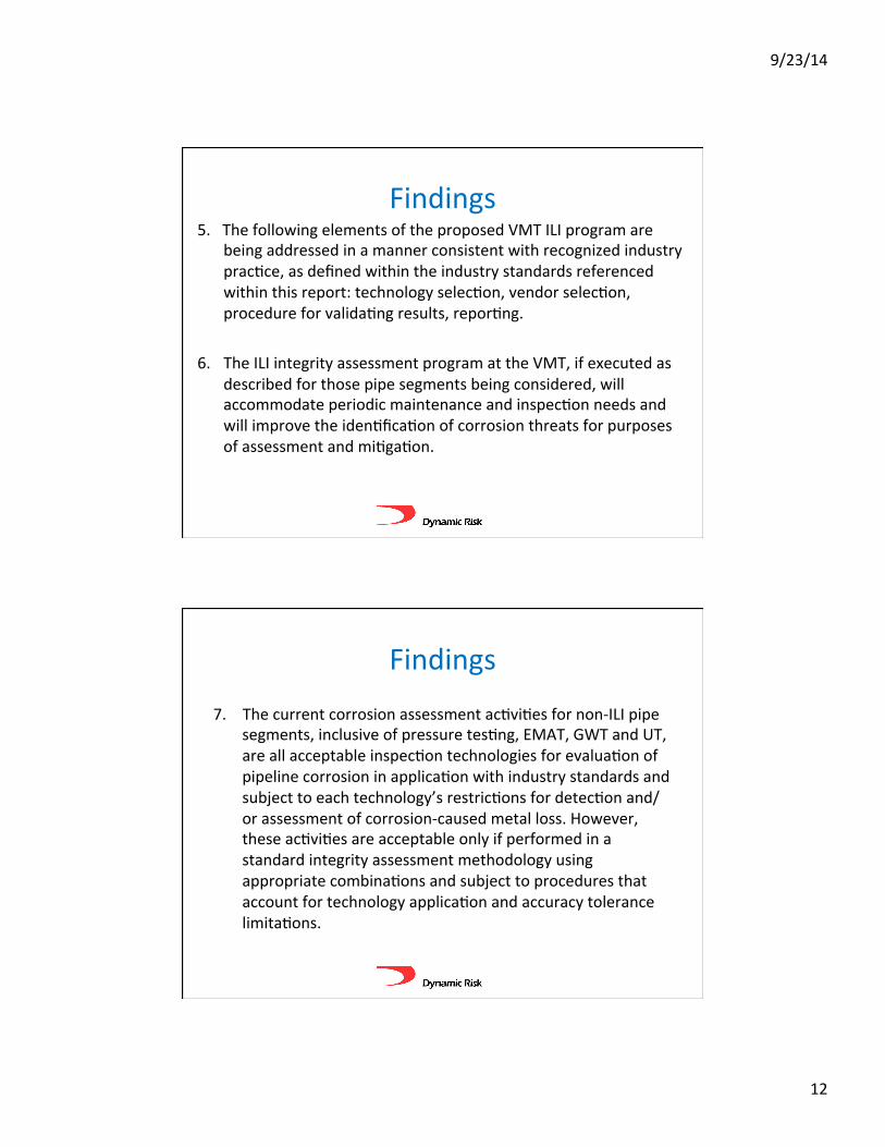
Findings 5. The following elements of the proposed VMT ILI program are
being addressed in a manner consistent with recognized industry prac6ce, as defined within the industry standards referenced within this report: technology selec6on, vendor selec6on, procedure for valida6ng results, repor6ng.
6. The ILI integrity assessment program at the VMT, if executed as
described for those pipe segments being considered, will accommodate periodic maintenance and inspec6on needs and will improve the iden6fica6on of corrosion threats for purposes of assessment and mi6ga6on.
Findings 7. The current corrosion assessment ac6vi6es for non-‐ILI pipe
segments, inclusive of pressure tes6ng, EMAT, GWT and UT, are all acceptable inspec6on technologies for evalua6on of pipeline corrosion in applica6on with industry standards and subject to each technology’s restric6ons for detec6on and/or assessment of corrosion-‐caused metal loss. However, these ac6vi6es are acceptable only if performed in a standard integrity assessment methodology using appropriate combina6ons and subject to procedures that account for technology applica6on and accuracy tolerance limita6ons.

9/23/14
13
Findings 8. The planned external inspec6ons of over water girth welds
on Berths 4 and 5 with UT, EMAT, and/or GWT will appropriately address the corrosion threats documented on these piping segments.
9. The annual sta6c head pressure test (per 33CFR156.70) of
the piping from the East Tank Farm to the ends of Berths 4 & 5 is not in alignment with accepted industry standards for pipeline pressure tes6ng, rela6ve to pressure, monitoring, and test dura6on. Considera6on should be given to the undertaking of addi6onal assessment measures (49 CFR 195 Subpart E).
Recommenda6ons -‐ VMT Inspec6on Program
• Consider 49 CFR Part 195 regula6ons along with industry standards as incorporated by reference, as guidance when developing the inspec6on program for the VMT piping.
• In order to provide increased opera6ng confidence,
undertake piping configura6on modifica6ons necessary to perform an ILI of the pipe segments downstream of the West Metering Building and/or to perform a hydrosta6c test program to pressures that will exceed normal opera6ng pressure, as per guidelines based upon 49 CFR Part 195 requirements.
9/23/14
14
Recommenda6ons -‐ VMT Inspec6on Program
• Determine piping system ILI and supplementary inspec6on periodicity requirements through assessment of ILI and other inspec6on results that can be combined with predicted corrosion growth rate calcula6ons. Periodicity requirements, as developed should be applied within future inspec6on program planning.
• Review 2014 inspec6on results of girth welds over water to
determine if girth weld integrity is an issue that needs to be addressed within the VMT facility inspec6on planning. Ensure that piping over water (or other piping) inspec6on ac6vity (EMAT, GWT and/or UT) procedures and repor6ng account for personnel qualifica6ons and technology limita6ons.
Recommenda6ons -‐ VMT Inspec6on Program • API 1163 and Alyeska TAPS experience can be applied as
guidelines when developing ILI procedures for the VMT; however, challenges specific to the VMT (short distances, extreme eleva6on changes and absence of pumps to control tool speed) will challenge the ability to keep the ILI tool within a required velocity threshold and will need to be addressed. Development of a VMT-‐specific ILI prac6ce document is required of Alyeska, who should communicate the development of this document.

9/23/14
15
Recommenda6ons -‐ VMT Inspec6on Program • Inves6gate methods and technology for applica6on of
supplementary inspec6ons on pipe segments designated for inclusion within the proposed ILI program. Results can provide con6nued opera6ng confidence during the interim 6me period leading up to ini6a6on of the ILI program and receipt of final repor6ng, which may take up to 6 months following comple6on of the pipe segment inspec6on.
• Review the facility specific risk and integrity assessment
methodologies outlined in API 1160, and supported by CEPA recommended prac6ce for Facili6es Integrity Management when next upda6ng the MP-‐166 series of integrity documents to include ILI as a new integrity assessment methodology.
Recommenda6ons -‐ VMT Inspec6on Program Monitoring
• Con6nue to monitor the VMT ILI integrity assessment program and prac6ce developments with specific focus on the ILI vendor selec6on process, applied ILI technologies, ILI data valida6on procedures and the corrosion assessment and repor6ng process.

9/23/14
16
Ques6ons – Original Construc6on Overview