CITY OF SUNNYVALE · CITY OF SUNNYVALE Addendum No. 2 DATE ... Item No. 2.12 Technical...
28
Addendum No. 2 Page 1 of 7 CITY OF SUNNYVALE Addendum No. 2 DATE ISSUED ON March 13, 2015 Invitation for Bids No. PW 15-01 Hypochlorite Conversion and Continuous Recycled Water Production Facilities Public Works Project No. UY-12/09-15 The above-referenced bid invitation is modified, as follows: Changes to Specifications: Item No. 2.01 Technical Specification, Table of Contents, ADD the following before 02072 DEMOLITION, CUTTING, PATCHING AND ITEMS TO BE SALVAGED: “02000 SOIL INVESTIGATION DATA Item No. 2.02 Technical Specification, Table of Contents, ADD the following after 16120 WIRE AND CABLE: 600 VOLT AND BELOW: “16125 PROCESS PIPING HEAT TRACING” Item No. 2.03 Technical Specification, Section 02000, Soil Investigation Data, which is attached to this addendum and consisting of 17 pages, ADD this new section to the Contract Documents.
Transcript of CITY OF SUNNYVALE · CITY OF SUNNYVALE Addendum No. 2 DATE ... Item No. 2.12 Technical...
Addendum No. 2 Page 1 of 7
CITY OF SUNNYVALE
Addendum No. 2
DATE ISSUED ON March 13, 2015
Invitation for Bids No. PW 15-01
Hypochlorite Conversion and Continuous Recycled Water Production Facilities
Public Works Project No. UY-12/09-15
The above-referenced bid invitation is modified, as follows:
Changes to Specifications:
Item No. 2.01
Technical Specification, Table of Contents, ADD the following before 02072 DEMOLITION,
CUTTING, PATCHING AND ITEMS TO BE SALVAGED:
“02000 SOIL INVESTIGATION DATA
Item No. 2.02
Technical Specification, Table of Contents, ADD the following after 16120 WIRE AND CABLE:
600 VOLT AND BELOW:
“16125 PROCESS PIPING HEAT TRACING”
Item No. 2.03
Technical Specification, Section 02000, Soil Investigation Data, which is attached to this
addendum and consisting of 17 pages, ADD this new section to the Contract Documents.

Addendum No. 2 Page 2 of 7
Item No. 2.04
Technical Specification, Section 15060, Paragraph 3.5 B.1.a. Table, DELETE in its
entirety and in its place, ADD the following Table:
“PIPE LINE SIZE GRAVITY OR PUMPED SPECIFIED TEST PRESSSURE TESTING MEDIUM
Up to and including 48 IN Gravity 25 psig or less Air or Water
All sizes Pumped 250 psig or less Water”
Item No. 2.05
Technical Specification, Section 15060, Paragraph 3.9 A.1.a., DELETE in its entirety
and in its place, ADD the following:
“a. “Piping symbol and service:
1) SHY – Sodium Hypochlorite. (Specification Section 15064 - carrier
tubing.)
2) D – Drain.
3) V – Vent.
4) OVF – Overflow.
5) PSO – Polymer solution.
6) SBS – Sodium Bisulfite.
7) SD – Storm Drain.
8) WP – Potable Water.
9) WR – Recycled Water.
10) Containment Pipe. (Specification Section 15065 - double containment
pipe.)”
Item No. 2.06
Technical Specification, Section 15060, Paragraph 3.9 B., DELETE in its entirety
and in its place, ADD the following:
“B. PIPING SPECIFICATION SCHEDULE – SYSTEM 2
1. General:
a. Piping symbol and service:
1) BW – Backwash Water.
2) FW – Filtered Water.
3) SE – Secondary Effluent/Applied Water.
b. Test Requirements:
1) Medium: Water.
2) Pressure:
a) BW: 30 psi.

Addendum No. 2 Page 3 of 7
b) FW: 50 psi.
c) SE: 30 psi.
3) Duration: 120 minutes.
c. Gaskets:
1) Flange: Compressed gasketing consisting of organic fibers
(Kevlar) and neoprene binder.
2) Push-on and mechanical sleeve couplings: Nitrile or neoprene.
2. System components:
a. Pipe size 4 IN through 42 IN:
1) Exposed service:
a) Material: Fabricated steel.
b) References:
(1) AWWA C200.
(2) Section 15061.
c) Lining: Fusion bonded epoxy (per AWWA C213), 12 mils
TDFT.
d) Coating: Fusion bonded epoxy (per AWWA C213), 12 mils
TDFT. Top coat per Section 09905.
e) Fittings:
(1) Fabricated steel.
(2) AWWA C208.
(3) Section 15061.
f) Joints: butt welded or grooved end couplings on approved
systems, mechanical sleeve couplings, or flanges are
indicated on the Drawings.
g) Valves for BW, FW, SE:
(1) Butterfly, see Section 15103.
(2) For valves requiring electric actuators, see Section
15100.
2) Buried service:
a) Material: Fabricated steel.
b) References:
(1) AWWA C200.
(2) Section 15061.
c) Lining: Fusion bonded epoxy (per AWWA C213), 12 mils
TDFT.
d) Coating: Fusion bonded epoxy (per AWWA C213), 12 mils
TDFT.
e) Fittings:
(1) Fabricated steel.

Addendum No. 2 Page 4 of 7
(2) AWWA C208.
(3) Section 15061.
f) Joints: Welded, except where mechanical sleeve
couplings, grooved end couplings, bell and spigot, or
flanges are indicated on the Drawings.
3. Notes:
a) Omit cement mortar coating of piping to be installed beneath
structures. This piping will be concrete encased.”
Item No. 2.07
Technical Specification, Section 15065, Paragraph 2.2 A., ADD the following
paragraph after paragraph 2.2 A.2:
“3. Provide split fittings for exposed hypochlorite pipes.”
Item No. 2.08
Technical Specification, Section 15100, Paragraph 1.1 B., ADD the following Table
after the first table:
“ACTUATOR TYPE SERVICE DEFINITION
EMTT Throttling (Modulating) Electric Motor Multi - Turn
EQTT Throttling (Modulating) Electric Motor Quarter - Turn
EMTI Isolating (Open – Close) Electric Motor Multi – Turn
EQTI Isolating (Open – Close) Electric Motor Quarter - Turn
EQTI-1 Isolating (Open – Spring Return to Close) Electric Motor Quarter – Turn”
Item No. 2.09
Technical Specification, Section 15100, Paragraph 1.1 B., ADD the following
paragraph after the two tables:
“2. Gates SG-93201, SG-93202, SG-93301, SG-93302, SG-93401, SG-93402,
SG-93501 and SG-93502 are existing. Replace actuators with electrical
actuators:
a. Gates:
1) Material: field verify.
2) Seating head: 12.5 FT.
3) Unseating head: 4 FT.
4) Invert elevation: 100.45. (Contractor to verify.)
5) Operating floor elevation: 114.95. (Contractor to verify.)
6) Stem diameter: Field verify.”
Addendum No. 2 Page 5 of 7
Item No. 2.10
Technical Specification, Section 15115, Paragraph 1.1 B, DELETE the following text
“SC” in row 2, column 3 of the Table:
Item No. 2.11
Technical Specification, Section 15115, Paragraph 2.2 E, DELETE the paragraph in
its entirety, and in its place, ADD the following paragraph:
“E. Design replacement gate SG-73503 to same layout dimensions as existing
gate.”
Item No. 2.12
Technical Specification, Section 15115, Paragraph 2.2 E.1 and 2., DELETE the
paragraph in its entirety.
Item No. 2.13
Technical Specification, Section 15115, Paragraph 2.3 D, DELETE the paragraph in
its entirety.
Item No. 2.14
Technical Specification, Section 15183, Paragraph 3.3 A. 1, DELETE the paragraph
in its entirety, and in its place, ADD the following paragraph:
“1. PVC Piping jackets for:
a. Potable water (3 IN and less).
b. Sodium hypochlorite (2 IN and less).
c. Sodium bisulfite (2 IN and less).”
Item No. 2.15
Technical Specification, Section 16125, Process Piping Heat Tracing, which is
attached to this addendum and consisting of 3 pages, ADD this new section to the
Contract Documents.
Changes to Plans:
Item No. 2.16
Sheet No. G-04, ADD the following to REFERENCE PIPING ABBREVIATIONS
“SE SECONDARY EFFLUENT/APPLIED WATER”

Addendum No. 2 Page 6 of 7
Item No. 2.17
Sheet No. C-05, at Grid 3-B DELETE call outs “3”-PSO” and in its place, ADD “3/4”-
PSO”.
Item No. 2.18
Sheet No. C-05, Note 4, DELETE in its entirety and in its place ADD:
“4. REPLACE EXISTING ¾” PSO PIPE TO NEW CHEMICAL VAULT AND CAP
EXISTING 1” AL AND 2” CLS PIPES. SEE SHEET X-02a FOR
DEMOLLITION.”
Item No. 2.19
Sheet No. C-12, at Grid 2-C ADD call outs “2”-WR” to irrigation and water supply.
Item No. 2.20
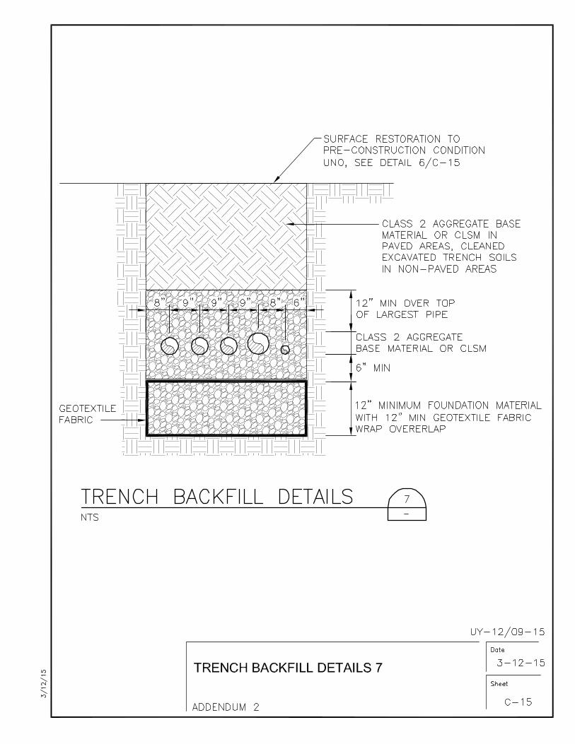
Sheet No. C-15, ADD Detail 7, which is attached to this addendum.
Item No. 2.21
Sheet No. P-06, ADD the following note:
“1. SLIDE GATES SG-93201, SG-93202, SG-93301, SG-93302, SG-93401, SG-
93402, SG-93501 AND SG-93502 ARE EXISTING. REPLACE EXISTING
GATE ACTUATORS WITH ELECTRIC ACTUATORS. SEE SHEET E-06 AND
SPECIFICATION SECTION 15100.”
Item No. 2.22
Sheet No. P-20, Detail 1, ADD the following notes:
“1. PROVIDE AIR/VACUUM VALVE (1/2”), MANUFACTURED BY VALMATIC,
FLOMATIC OR EQUAL.”
2. PROVIDE PVC ISOLATION BALL VALVE.”
Item No. 2.23
Sheet No. E-03, DELETE Note 4 in its entirety, and in its place, ADD the following:
“4. Replace existing age and operator with new gate and electric actuator, and
connect to I/O Box.”

Addendum No. 2 Page 7 of 7
All other terms and conditions remain the same.
This Addendum consists of seven (7) pages (Addendum Items 2.01 through 2.23,
plus attachments) and forms a part of the Bid Documents and modifies the original
documents Dated February 2015.

City Project No. UY-12/09-15 Invitation for Bids #PW 15-01 City of Sunnyvale Hypochlorite Conversion and Continuous Recycled Water Production Facilities Technical Specifications Addendum No. 2 Page TS – 02000-1 TS – (Corrected page numbering to be assigned in Conformed Documents)
SOIL INVESTIGATION DATA 02000
SECTION 02000
SOIL INVESTIGATION DATA
PART 1 - GENERAL
1.1 INVESTIGATION
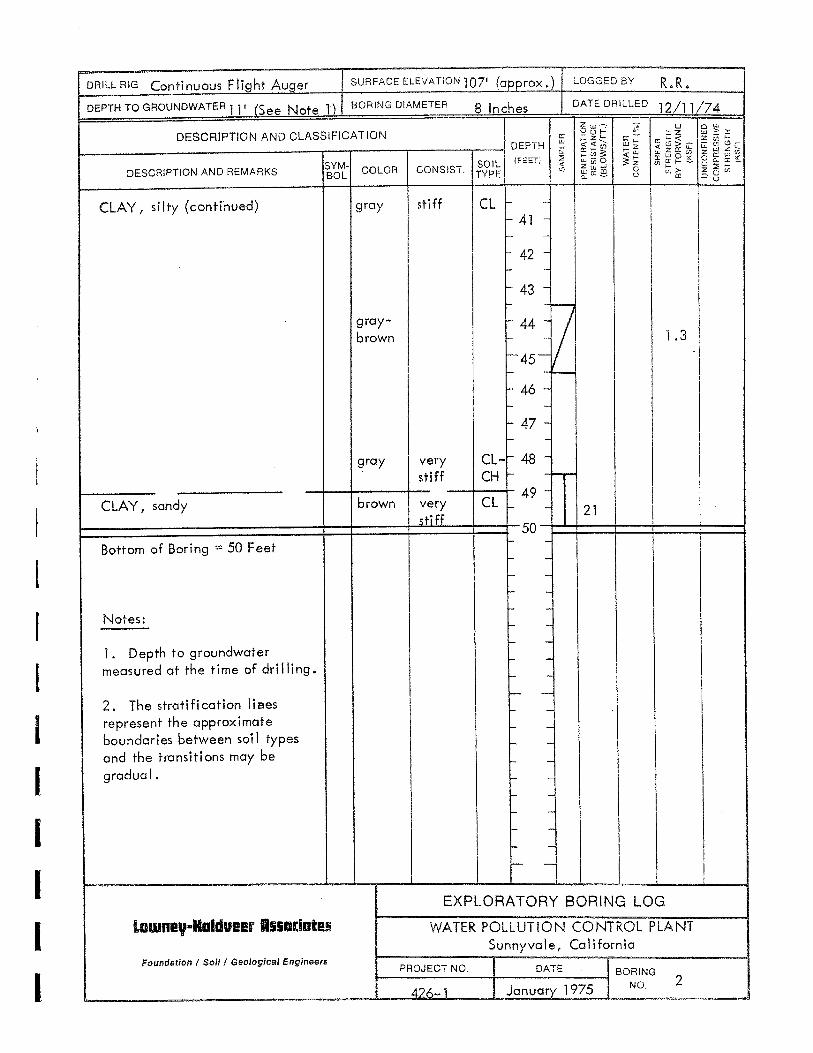
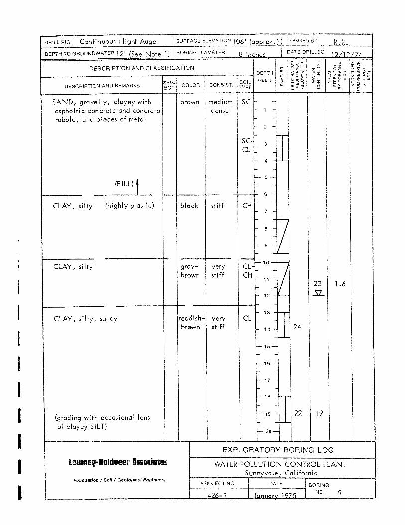
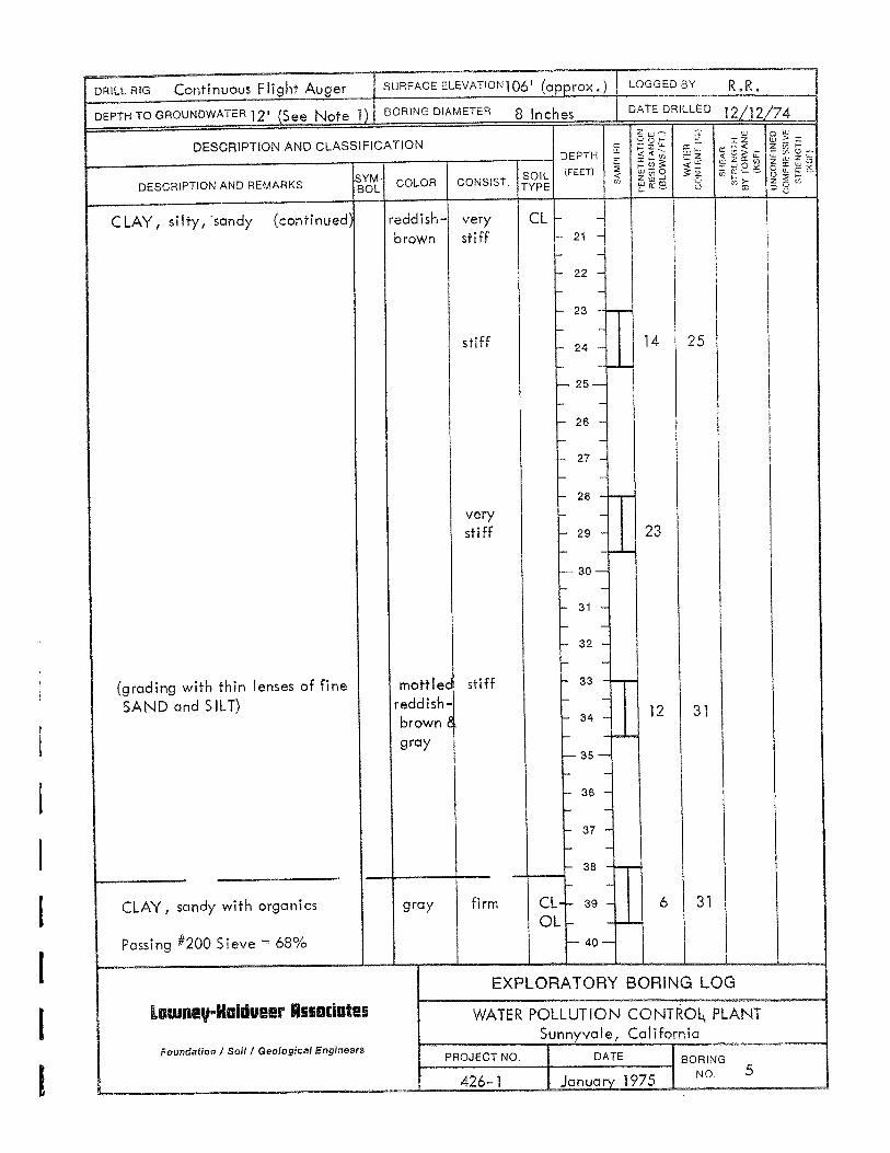
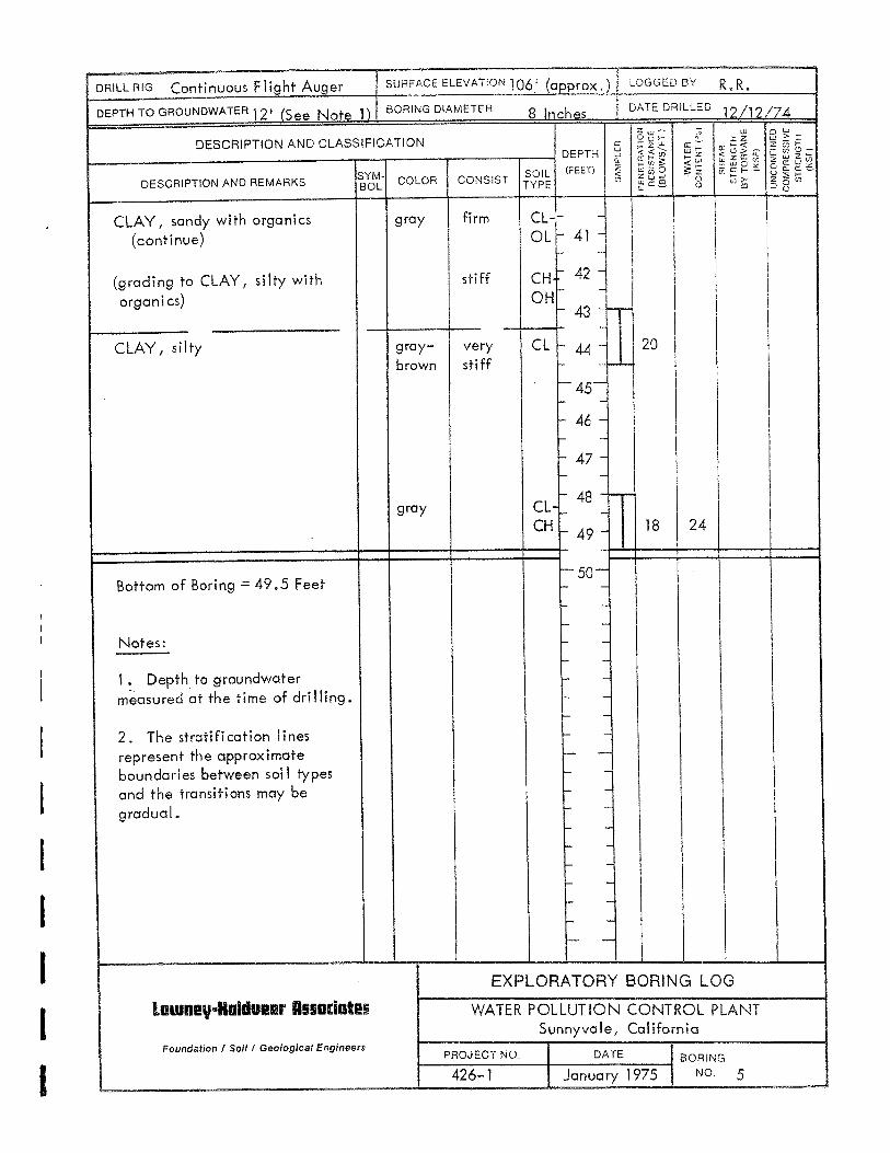
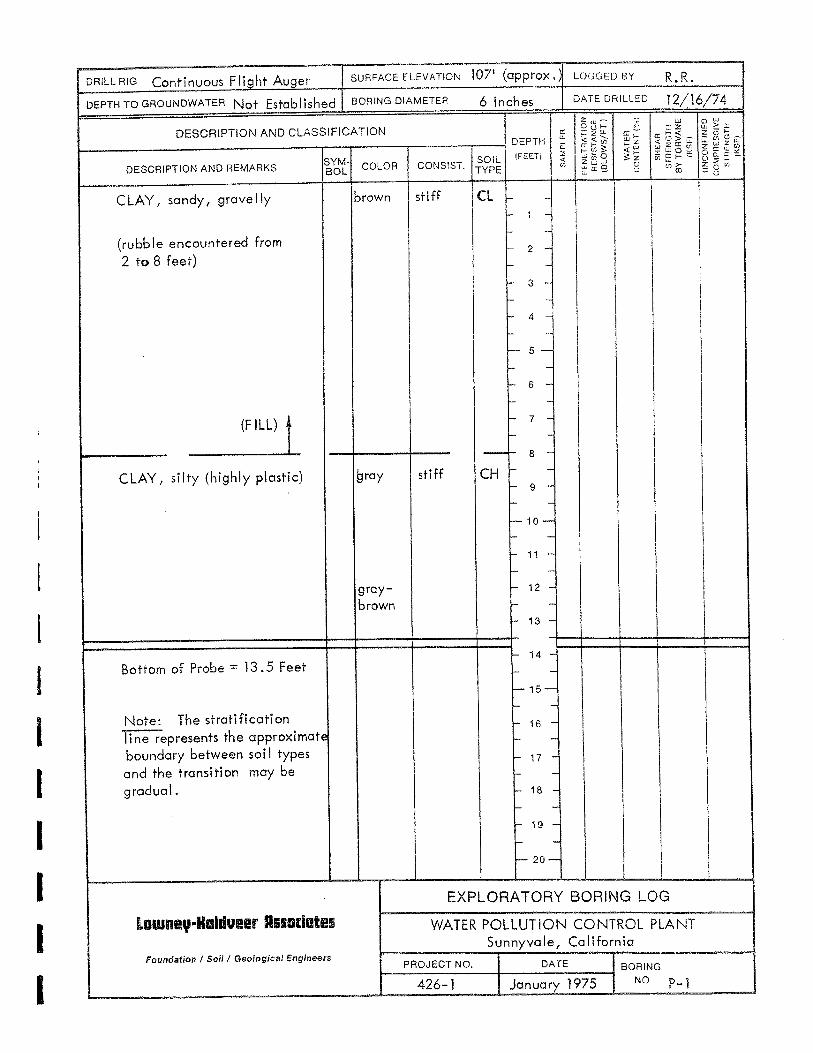
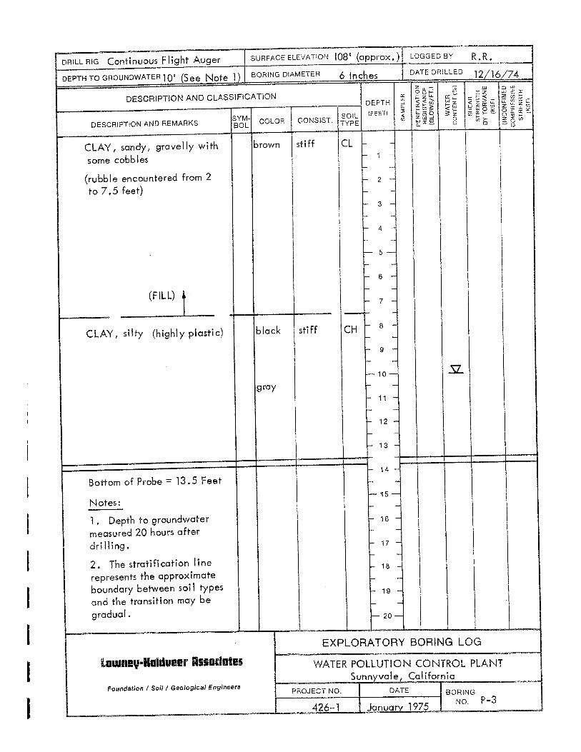
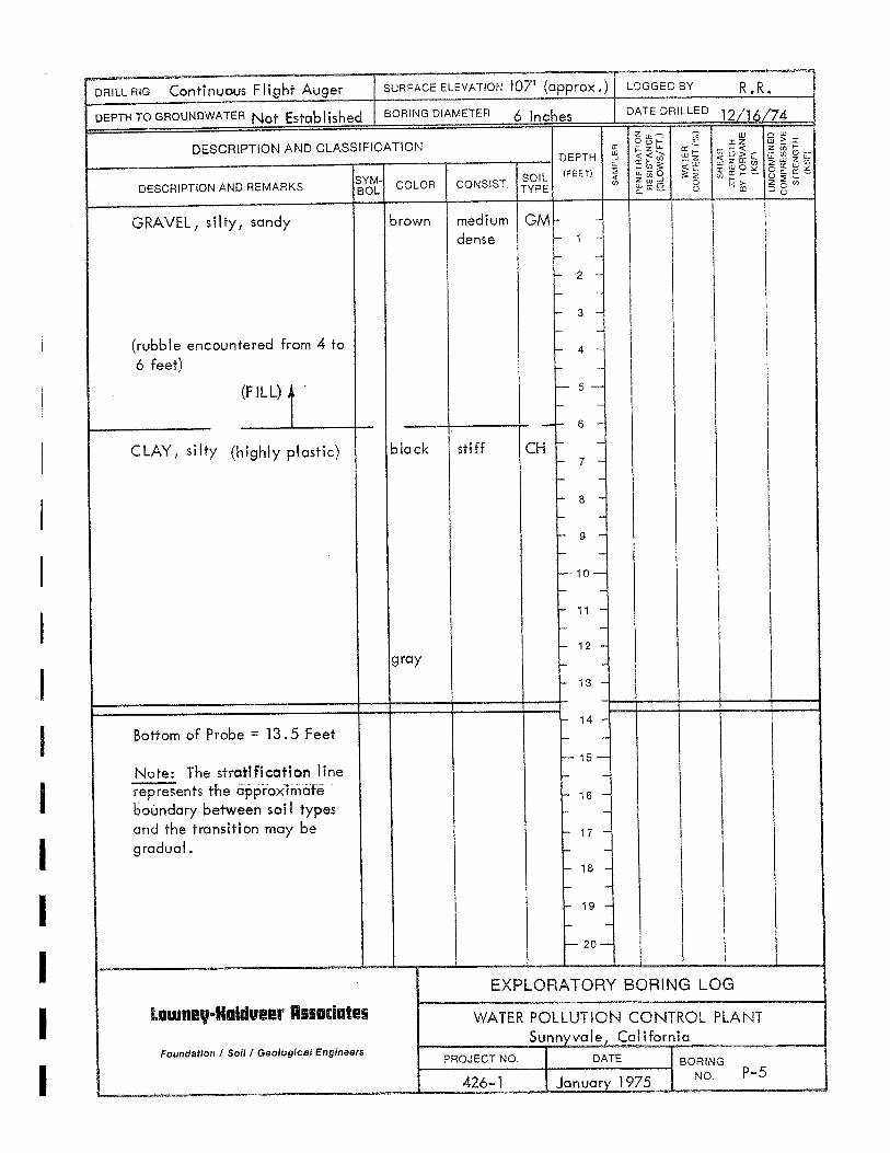
A. Soil and subsurface investigations were conducted at the plant site for previous projects. A Geotechnical Memorandum was prepared for this project: 1. Title: Geotechnical Memorandum, Sodium Hypochlorite Disinfection System Project,
Sunnyvale Water Pollution Control Plant. 2. Date: June 21, 2013 3. Author: Jacobs Associates, Engineers/Consultants
B. A copy of the soils boring logs is included at the end of this section.
C. Reproductions of information will NOT be available or made at the office of the Engineer.
D. This report of explorations and tests of subsurface conditions at the site has been utilized by the Engineer in preparation of the Contract Documents. Bidder may rely upon the accuracy of the "technical" data contained in such reports but not upon nontechnical data, interpretations or opinions contained therein or for the completeness thereof for the purposes of bidding or construction.
E. This memorandum is not part of the Contract Documents but the technical data contained therein upon which Bidder is entitled to rely are incorporated therein by reference. Such technical data is boring method, location and logs; and laboratory test methods and results.
F. Before submitting a Bid, each Bidder will, at Bidder's own expense, make or obtain any additional examinations, investigations, explorations, tests and studies and obtain any additional information and data, which pertain to the physical conditions, surface or subsurface, at or contiguous to the site or otherwise which may affect cost, progress, performance or furnishing of the Work and which Bidder deems necessary to determine its Bid for performing and furnishing the Work in accordance with the time, price and other terms and conditions of the Contract Documents.
END OF SECTION
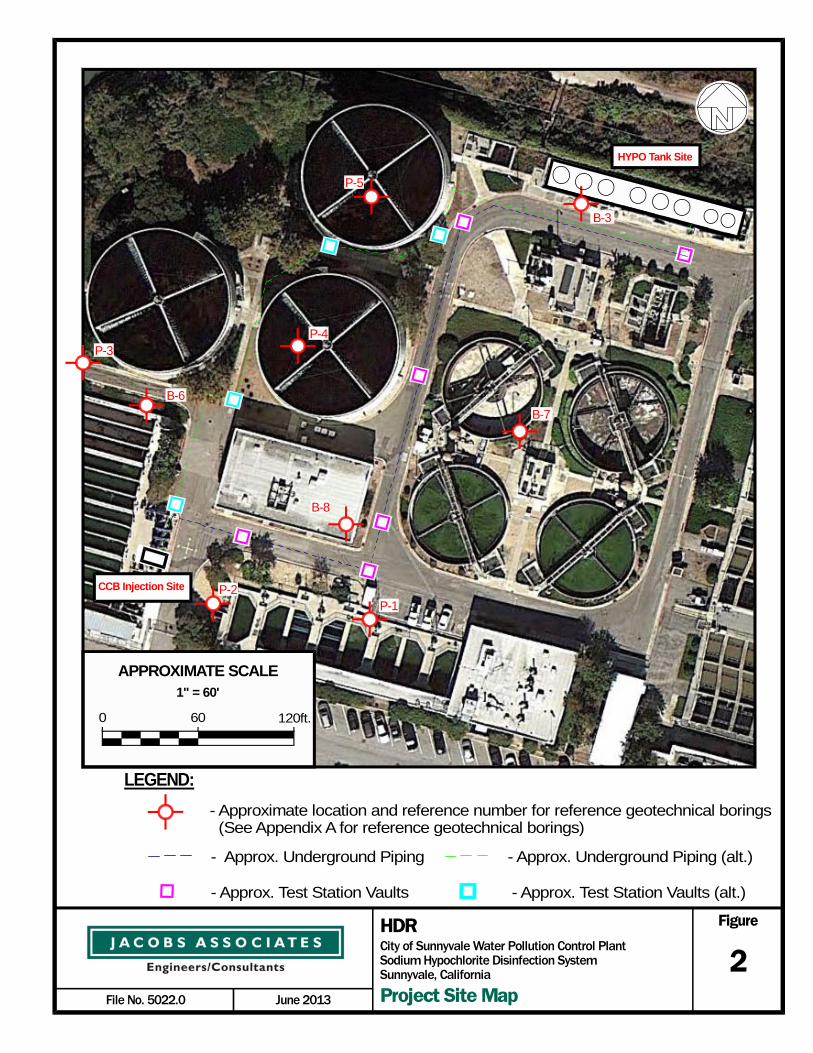
Figure
2June 2013File No. 5022.0
City of Sunnyvale Water Pollution Control PlantSodium Hypochlorite Disinfection SystemSunnyvale, California
HDR
Project Site Map
CCB Injection Site
LEGEND:
- Approximate location and reference number for reference geotechnical borings (See Appendix A for reference geotechnical borings)
- Approx. Underground Piping
0 60
1" = 60'
APPROXIMATE SCALE
120ft.
B-3
HYPO Tank Site
P-5
B-7
B-8
B-6
P-2P-1
P-4P-3
- Approx. Test Station Vaults - Approx. Test Station Vaults (alt.)
- Approx. Underground Piping (alt.)


City Project No. UY-12/09-15 Invitation for Bids #PW 15-01 City of Sunnyvale Hypochlorite Conversion and Continuous Recycled Water Production Facilities Technical Specifications Addendum No. 2 Page TS – 16125-1
TS – (Corrected page numbering to be assigned in Conformed Documents)
PROCESS PIPING HEAT TRACING 16125
SECTION 16125
PROCESS PIPING HEAT TRACING
PART 1 - GENERAL
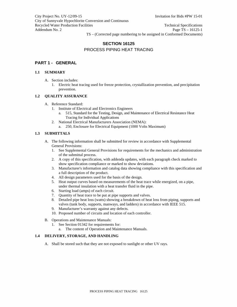
1.1 SUMMARY
A. Section includes: 1. Electric heat tracing used for freeze protection, crystallization prevention, and precipitation
prevention.
1.2 QUALITY ASSURANCE
A. Reference Standard: 1. Institute of Electrical and Electronics Engineers
a. 515, Standard for the Testing, Design, and Maintenance of Electrical Resistance Heat Tracing for Individual Applications
2. National Electrical Manufacturers Association (NEMA): a. 250, Enclosure for Electrical Equipment (1000 Volts Maximum)
1.3 SUBMITTALS
A. The following information shall be submitted for review in accordance with Supplemental General Provisions: 1. See Supplemental General Provisions for requirements for the mechanics and administration
of the submittal process. 2. A copy of this specification, with addenda updates, with each paragraph check marked to
show specification compliance or marked to show deviations. 3. Manufacturer's information and catalog data showing compliance with this specification and
a full description of the product. 4. All design parameters used for the basis of the design. 5. Heat output curves based on measurements of the heat trace while energized, on a pipe,
under thermal insulation with a heat transfer fluid in the pipe. 6. Starting load (amps) of each circuit. 7. Quantity of heat trace to be put at pipe supports and valves. 8. Detailed pipe heat loss (watts) showing a breakdown of heat loss from piping, supports and
valves (tank body, supports, manways, and ladders) in accordance with IEEE 515. 9. Manufacturer’s warranty against any defects. 10. Proposed number of circuits and location of each controller.
B. Operations and Maintenance Manuals: 1. See Section 01342 for requirements for:
a. The content of Operation and Maintenance Manuals.
1.4 DELIVERY, STORAGE, AND HANDLING
A. Shall be stored such that they are not exposed to sunlight or other UV rays.

City Project No. UY-12/09-15 Invitation for Bids #PW 15-01 City of Sunnyvale Hypochlorite Conversion and Continuous Recycled Water Production Facilities Technical Specifications Addendum No. 2 Page TS – 16125-2
PROCESS PIPING HEAT TRACING 16125
PART 2 - PRODUCTS
2.1 GENERAL
A. For “or equal” items, refer to Item 19 Substitutions and Item 20 Specified “Or Equal” Items in Supplemental General Provisions.
2.2 OPERATING CONDITIONS
A. Maintain piping and tank and contents at 60 DegF with 20 DegF ambient temperature, a 20 mph wind speed and minimum 10 percent safety factor with the lines full and at no flow conditions.
2.3 HEAT TRACE CABLE
A. Acceptable Product: 1. Thermon model BSX with accessories; Raychem series BTV with accessories; or equal,
modified as required to meet the specifications.
B. Material: 1. Heat trace cable shall be parallel, self-regulating type, designed for indoor and outdoor
exposures. Cable shall be radiation cross linked. Ground braid shall be tin plated copper wire. The outer jacket shall provide complete, continuous coverage over the braid to prevent corrosion of the braid. Provide a two pass cable with banding tape that is compatible with sodium bisulfite exposure.
2. Outer Jacket Material: fluoropolymer 3. Heat output: 3 watts/ft @ 50 DegF; 110 VAC-1 phase. Include power connection kits,
splice and tee kits, end seals, application tapes, warning labels, and other accessories required for a complete system. UL Listed.
2.4 HEAT TRACE CONTROLLER
A. Acceptable Products: 1. Thermon model TC 101a and TC 202a; or equal, modified as required to meet the
specifications.
B. Materials/Equipment: 1. Microprocessor-based controller with digital information display shall provide continuous
monitoring of heat trace circuit analyzing temperature through a hard-wired RTD. Controller shall energize if temperature drops below a preset point. Controller shall provide a soft start feature, with a 3 minute ramp up from 0-100 percent. Controller shall be equipped with local alarm to alert maintenance personnel if heat trace circuit is interrupted. Controller shall have the capability of performing a self-diagnostic check on the system and advising maintenance personnel of the exact nature of any circuit problems. Controller shall be fully compatible with heat trace cable.
2. Controller shall provide monitoring and control for one or two circuits, per Drawings. 3. Controller power supply shall be 110V, 1-phase, 60 Hz with adjustable ground fault
detection. Heat sinks for the solid state relays shall be internal. Unit shall be enclosed in a NEMA 4X stainless steel panel. Controller shall have battery back-up system to retain programmed parameters in the event of a power failure. Controller shall have network capabilities enabling monitoring and programming form a central location.
City Project No. UY-12/09-15 Invitation for Bids #PW 15-01 City of Sunnyvale Hypochlorite Conversion and Continuous Recycled Water Production Facilities Technical Specifications Addendum No. 2 Page TS – 16125-3
PROCESS PIPING HEAT TRACING 16125
2.5 CONNECTION KITS, END SEALS, SPLICE AND TEE KITS
A. Materials: 1. Heat trace connection, end, splice, and tee kits shall be designed to meet or exceed the life
of the heat trace cable. Non-metallic connection kits shall be rated NEMA 4X. Temperature sensors shall be RTD. End of circuit continuity shall be accomplished with lighted end seals, utilizing high intensity green LED lamps with domed covers for day and night visibility.
PART 3 - EXECUTION
3.1 INSTALLATION
A. Install electric heat tracing systems to bisulfite piping in accordance with the Drawings, and piping specification Section, and the manufacturer’s recommendations.
B. Insulation shall be provided over all heat tracing per the Specification Section 15183.
C. Install standard labels on each pipeline traced, at intervals not to exceed 10 FT, to indicate that the pipe is electrically heat traced.
3.2 TESTING
A. Megger the cables at the manufacturer’s recommended voltage level three (3) times: 1. Before installation. 2. After attachment to pipe, but before insulation is installed. 3. After pipe insulation is installed, but before energizing.
3.3 TRAINING
A. Training shall conform to Specification Section 01650. The number of training sessions and hours for each craft shall conform to the requirements of the Specification Section 01650.
END OF SECTION