David Hausheer, Jayesh Pandey, Burkhard Stiller The ... · Origin: ETH Zürich, TIK Doc ID:...
43
Eidgenössische Technische Hochschule Zürich Swiss Federal Institute of Technology Zurich TIK-Report Nr. 150, August 2002 Institut für Technische Informatik und Kommunikationsnetze Computer Engineering and Networks Laboratory David Hausheer, Jayesh Pandey, Burkhard Stiller The Implementation of the CPS Scenario
Transcript of David Hausheer, Jayesh Pandey, Burkhard Stiller The ... · Origin: ETH Zürich, TIK Doc ID:...
Eidgenössische Technische Hochschule ZürichSwiss Federal Institute of Technology Zurich
TIK-ReportNr. 150, August 2002
Institut für Technische Informatik und KommunikationsnetzeComputer Engineering and Networks Laboratory
David Hausheer, Jayesh Pandey,Burkhard Stiller
The Implementation of the CPS Scenario
David Hausheer, Jayesh Pandey, Burkhard Stiller:The Implementation of the CPS ScenarioAugust 2002Version 1TIK-Report Nr. 150
Computer Engineering and Networks Laboratory,Swiss Federal Institute of Technology (ETH) Zurich
Institut für Technische Informatik und Kommunikationsnetze,Eidgenössische Technische Hochschule Zürich
Gloriastrasse 35, ETH-Zentrum, CH-8092 Zürich, Switzerland

Fifth Framework Project 11429 The Implementation of the CPS Scenario
© Copyright 2002, the Members of the M3I Consortium
Version 1.0 Page 1 of 41
Market Managed Multi-service Internet
M3IEuropean Fifth Framework Project IST-1999-11429
Deliverable 15.3 Part IIThe Implementation of the CPS Scenario
The M3I Consortium
Hewlett-Packard Ltd, Bristol UK (Coordinator)BT Research, Ipswich UKEidgenössische Technische Hochschule, Zürich, CHDarmstadt University of Technology, Darmstadt DTelenor, Oslo NAthens University of Economics and Business, Athens GRForschungszentrum Telekommunikation Wien, A
© Copyright 2002, the Members of the M3I Consortium
For more information on this document or the M3I project,please contact:
Hewlett-Packard Ltd,European Projects Office,Filton Road,Stoke Gifford,BRISTOL BS34 8QZ,UKPhone: (+44) 117-312-8631Fax: (+44) 117-312-9285E-mail: [email protected]

The Implementation of the CPS Scenario Fifth Framework Project 11429
© Copyright 2002, the Members of the M3I Consortium
Page 2 of 41 Version 1.0
Document Control
Title: The Implementation of the CPS Scenario
Type: Integration and Implementation Documentation
Editor: Burkhard Stiller ETH Zürich, TIK
E-mail: [email protected]
Origin: ETH Zürich, TIK
Doc ID: WP6-CAS-CPS-Impl-1.0
AMENDMENT HISTORY
Legal NoticesThe information in this document is subject to change without notice.The Members of the M3I Consortium make no warranty of any kind with regard to this document, including,but not limited to, the implied warranties of merchantability and fitness for a particular purpose. The Membersof the M3I Consortium shall not be held liable for errors contained herein or direct, indirect, special, incidentalor consequential damages in connection with the furnishing, performance, or use of this material.
Version Date Author Description/Comments
V 1.0 February 8, 2002 David Hausheer, Jayesh Pan-dey, Burkhard Stiller
Final version
Fifth Framework Project 11429 The Implementation of the CPS Scenario
© Copyright 2002, the Members of the M3I Consortium
Version 1.0 Page 3 of 41
Table of Content
1 Introduction ............................................................................................................5
2 CPS Fine Design and Implementation .................................................................52.1 Overview ............................................................................................................................... 5
2.2 Development Environment .................................................................................................... 7
2.3 Package Structure ................................................................................................................ 7
2.4 Component Type Classes ..................................................................................................... 82.4.1 Fluid ......................................................................................................................... 82.4.2 CPSMediation .......................................................................................................... 92.4.3 CPSConnector ......................................................................................................... 92.4.4 UDPCPSTariffWriter ................................................................................................ 92.4.5 CPSBilling .............................................................................................................. 11
2.5 Data Type Classes .............................................................................................................. 112.5.1 FlowDataEntry ....................................................................................................... 112.5.2 CPSMediationRecord ............................................................................................ 122.5.3 CPSCustomer ........................................................................................................ 122.5.4 CPSSessionFragment ........................................................................................... 132.5.5 CPSSessionCharacterisation ................................................................................ 132.5.6 CPSTariff ............................................................................................................... 13
2.6 Data Flows .......................................................................................................................... 14
2.7 User Interface ..................................................................................................................... 15
2.8 Connection Setup ............................................................................................................... 15
3 Networking Environment ....................................................................................163.1 Overview Testbed ............................................................................................................... 16
3.2 DiffServ Environment .......................................................................................................... 17
3.3 Component Location ........................................................................................................... 17
4 Experiment Setup ................................................................................................184.1 Traffic Generation ............................................................................................................... 18
4.1.1 Requirements ........................................................................................................ 184.1.2 Tools Evaluation .................................................................................................... 184.1.3 Traffic Pattern ........................................................................................................ 19
4.2 DBS Configuration .............................................................................................................. 20
4.3 Experiment Parameters and Timescales ............................................................................ 21
4.4 Threshold Calculation ......................................................................................................... 22
4.5 Experiment Invocation Process (Running the Scenario) .................................................... 24
5 Experiment Results .............................................................................................265.1 The Relevance of the Traffic Pattern .................................................................................. 27
5.2 Parameter Tuning ............................................................................................................... 295.2.1 Varying the Charging Interval ................................................................................ 295.2.2 Varying the CPS Thresholds ................................................................................. 30
6 Summary and Conclusions ................................................................................31
7 Future Work .........................................................................................................327.1 Comparison of CPS with ECN ............................................................................................ 32
8 Reference .............................................................................................................32
9 Abbreviations .......................................................................................................34

The Implementation of the CPS Scenario Fifth Framework Project 11429
© Copyright 2002, the Members of the M3I Consortium
Page 4 of 41 Version 1.0
10 Acknowledgements ...........................................................................................35
11 Appendix ............................................................................................................3511.1 Initialization Design (User End) ......................................................................................... 35
11.2 Installation and Operating Issues ...................................................................................... 3911.2.1 CPSManager ....................................................................................................... 3911.2.2 CPSCreator ......................................................................................................... 3911.2.3 CSDaemon .......................................................................................................... 4011.2.4 CSServerThread .................................................................................................. 4011.2.5 NeMaCServer ...................................................................................................... 4011.2.6 NeMaCDaemon ................................................................................................... 4011.2.7 NeMaCServerThread ........................................................................................... 41
Fifth Framework Project 11429 The Implementation of the CPS Scenario
© Copyright 2002, the Members of the M3I Consortium
Version 1.0 Page 5 of 41
1 IntroductionPricing schemes form the essential part of a business model for Internet Service Providers(ISP). A pricing scheme applied to the transport of data in an IP network needs to cope witha number of issues of the IP technology utilized as well as with ISP’s economicrequirements and goals.
The Cumulus Pricing Scheme (CPS) [7] proposes a paradigm shift and argues that theproblem of Internet pricing is not a matter of complexity, but instead a problem of mappingmultiple and multi-dimensional time-scales. The developed scheme shows a simple,transparent, market-managed, and feasible Internet pricing scheme1.
CPS is a flat rate scheme founding on SLA contracts between customers and ISP, wherebythe customer may be an ISP. It provides individual and dynamic adaption of flat rates onlong-time scales due to SLA contract violations or renegotiations. The compliance of thecontract is motivated and supported by a feedback mechanism, the Cumulus Points (CP),and the liberty for deviations on short-time scales, due to statistical metering and averageCP accumulation mechanisms [13], [14], [15]. With respect to the contract and its technicalparameters, CPS offers in its basic concept no dedicated metric to be applied solely,although the volume and the bandwidth a user may utilize during communications states awell-known example.
The CPS scenario has been developed, implemented, and experienced with. Since CPSdetermines a new idea, additional conceptional and theoretical topics are under detailedinvestigation. This concerns mainly the process of gathering knowledge and experiences incontract metrics, i.e. contract terminology and contract negotiation. Furthermore, heuristicsare collected with the intention to define appropriate stimuli and parameter for a simulationinitialization and a detailed scenario definition.
This document presents the fine design and implementation of the CPS scenario andpresents those details on how it can be embedded into the Charging and AccountingSystem (CAS) [17] developed within the M3I project. After that an overview on thenetworking environment is given on which experiments have been running. The experimentsetup and component configuration is described step by step. Finally, results from theseexperiments are presented and discussed.
2 CPS Fine Design and ImplementationThe fine design of the Cumulus Pricing Scheme (CPS) scenario for the M3I project followsthe design dimensions outlined in [16]. The following section gives an overview on howCPS can be embedded in the CAS architecture. After that the development environment forthe CPS implementation is presented and the implementation is described in detail.
2.1 Overview
The Charging and Accounting System (CAS) [17] developed within the M3I project providesa generic and modular charging system in support of various pricing schemes applicable todifferent communication technologies [12], [15]. Figure 1 gives an overview on how the
1.In M3I terminology [10], the developed scheme is determined by all features of a tariff scheme.However, for comparisons with “traditional” Internet “pricing work”, the older and less precise term hasbeen utilized. Pricing Mechanisms, as described in [6], are applicable.

The Implementation of the CPS Scenario Fifth Framework Project 11429
© Copyright 2002, the Members of the M3I Consortium
Page 6 of 41 Version 1.0
CPS scenario can be adapted to the CAS. It is important to note that the CAS doesn’t haveto be changed for that purpose, it is scenario independent.
In a few words the CAS simply provides two components, each of which with anappropriate database. They are able to account and charge for any service. It is up to thedesigner of a particular scenario, what the CAS is actually accounting and charging for. Forthis purpose the respective components need to be instantiated accordingly.
In the CPS scenario the CAS needs to account for traffic flows, e.g., in terms of volume orbandwidth, and charge for the consumption of it over a certain time duration (charginginterval). This charging period is also termed a session, since in the CPS scenario theduration of all sessions are of equal size during the entire contract, e.g., a week or a month,and this dimension is usually much longer than the duration of a single flow.
To adapt the CPS scenario to the CAS, basically components termed with a preceding“CPS” had to be implemented. There are on one hand data type components describing thestructure of the data that is handled by the system. E.g., two componentsCPSSessionFragment and CPSSessionCharacterization provide the data structures usedby the CAS to store the data elements in the databases. In the CPS scenario this mayencompass volume or bandwidth data of the traffic measured and information about whomthe traffic belongs to and how it needs to be charged, described by, e.g., user id, contract id,service id, and session id.
On the other hand, there are components that need to produce and process this data, e.g.,the CPSConnector component that connects the CAS to the mediation component. It isresponsible for the combination of session information provided by the CPSCustomercomponent with the flow data provided by the CPSMediation component.
Fluid
Charge
Calculation
CPSConnector
Accounting Accounting
DatabaseCharging
Database
Configuration
FilesCPSBilling
CAS
SNMP NeTraMet
CPSMediationRecord
CPSTariffCPSSession
Fragment
CPSSession
Characterization
CPSMediation
FlowDataEntry
CPSCustomer
Figure 1: Overview on the CPS Scenario Embedded in the CAS

Fifth Framework Project 11429 The Implementation of the CPS Scenario
© Copyright 2002, the Members of the M3I Consortium
Version 1.0 Page 7 of 41
The real CPS related mechanisms are implemented in the CPSTariff component thatprovides the thresholds and reaction rules, and in the CPSBilling component which servesas an interface to the customer specifying the red or green cumulus points a customerreceives for a specific usage of the service and the accumulation of them over time.
2.2 Development Environment
This section briefly describes the technology used for implementing and running the CPSscenario. Later on in Section 3.3 it is shown where different components have been placedin the networking environment in order to run the experiments.
Programming language: Since the CAS is completely written in Java to be able todistribute it over several machines, the CPS scenario had to be developed using samelanguage. For the implementation of CPS, Java 2 has been used as part of JDK 1.2 [23].Java is available for many platforms. The code is therefore portable and has successfullybeen tested on FreeBSD, Solaris and Windows.
Database: The CAS needs to be connected to a SQL-capable database, which it uses tostore the Accounting and Charging records. As proposed in [17], the MySQL database [24]was chosen for this purpose.
Operating System: As mentioned above, the implementation can be ported to manydifferent platforms. For the experiments described later in Section 4, a FreeBSD / Solaristestbed was used, but the Java code could also be running on a Windows machine. Thenetworking environment used for the experiments is described more detailed in Section 2.8.
Other Tools: In order to provide a real and complete environment to run the CPSscenario quite a few other components needed to be obtained and installed in the testbed.The traffic measurements on the meter hosts are done by NeTraMet [26]. NeMaC [26] isused as the meter manager and Fluid [21] serves as a Java interface to the meter. Fluid hasslightly been changed; this component is described more detailed in Section 2.4.1. Furtheron Fluid uses the SNMPv2 Java class library from AdventNet [22] to communicate with themeter over the SNMP protocol. Finally, to run the experiments, DBS [20] was chosen as thetraffic generator, as it fulfilled most of the requirements. An overview on various evaluatedtraffic generation tools is given in Section 4.1.
2.3 Package Structure
To obtain a clear view on the organization of the software implemented, the packagestructure and inheritance relations of the Java source code is presented in Figure 2.Afterwards, detailed class descriptions are discussed in Section 2.4 and Section 2.5.
For the CPS scenario a new package org.m3i.examples.ethz.CPSdemo was created andembedded in the overall package structure used in the M3I project. Most of these Javaclasses extend or implement other components of the M3I structure. Apart from theseanother three classes have been added to the new package. The CPSCustomer class hasbeen created to provide the session information used in the CAS. It can easily be replacedlater by the customer support component, which is not part of the CAS yet. TheCPSMediation class is used to create and manage Fluid objects and transforms the flowdata into mediation records. Finally, Fluid has also been added to the new package.

The Implementation of the CPS Scenario Fifth Framework Project 11429
© Copyright 2002, the Members of the M3I Consortium
Page 8 of 41 Version 1.0
2.4 Component Type Classes
As in the CAS, the relevant classes of the CPS scenario can be grouped into two majorgroups. On one hand there are data type classes that are representing the structure of thedata which gets passed around. On the other hand there are component type classes thatare handling this data. This section presents these component classes while the nextsection will present the data classes. A short description of these classes and theirfunctionality will be given in each case. This includes a description of each method and itspurpose. However, this description will not contain any details about passed parametersand also fields of classes will not be shown. For more detailed information please have alook at the code itself.
2.4.1 Fluid
Fluid is a Java interface to NeTraMet [26] and was made within the scope of [21]. It usesthe SNMPv2 Java class library from AdventNet [22] to connect to and read from theNeTraMet meter using the rulefiles uploaded to NeTraMet by NeMaC [26]. Using thearchitecture design described in [28], Fluid is the meter reader, NeMaC the meter managerand NeTraMet the meter. NeTraMet records the traffic data, e.g., the volume, of everysingle packet going through a specific network interface and combines them into flows andaggregates them over time. In doing so, it follows the policy defined in the rulefile providedby the manager. Periodically, Fluid collects the flow data, using the SNMP protocol and theFlow Meter MIB [28].
CollectingCasModule
Accounting
ChargeCalculation
SessionFragment
SessionCharacterisation
Connector
MediationRecord
CPSConnector
CPSBilling
CPSSessionCharacterisation
CPSSessionFragment
CPSTariff
CPSMediationRecord Fluid
UDPCPSTariffWriter
m3
i
Tariff
org
pri
ce
tari
ff
ch
arg
e_
ac
cs
es
sio
nm
ed
iati
on
ex
am
ple
s
eth
z
org.m3i.examples.ethz.CPSdemo
CPSCustomer
CPSMediation
Figure 2: CPS Scenario Package Structure

Fifth Framework Project 11429 The Implementation of the CPS Scenario
© Copyright 2002, the Members of the M3I Consortium
Version 1.0 Page 9 of 41
Fluid originally provided a Java applet interface and some additional methods that has beenremoved in this version. Some other methods have been added to provide the interface tothe CPSMediation class. These new methods are shown in Table 1.
Herein the rest of the functionality provided by Fluid is described shortly. To connect Fluid tothe meter, the specific hostname, SNMP portnumber and the correct community name andruleset number need to be provided. The init method starts the SNMP API and loads theMIB files corresponding to the Flow Meter MIB [28]. The method dothemainquery, which isperiodically invoked by the getNextData method, creates a session with the meter, anddoes synchronous and asynchronous queries to it to receive the flow data information. Thisinformation is then handed over to the CPSMediation class.
2.4.2 CPSMediation
The CPSMediation class instantiates a Fluid object for every meter host to collect themeasured flow data by that host. As NeTraMet only provides the aggregated data over timethe previous values need to be stored and to produce mediation records the differencebetween two entries is used.
From time to time this internal storage of flow data needs to be cleaned up. Therefore thetimeout value of every flow is periodically checked using the method removeExpiredFlows.The main methods are described in Table 2.
2.4.3 CPSConnector
As the CPSConnector class inherits from the generic connector classorg.m3i.mediation.Connector, it needs to implement several methods of that class. Thesemethods are not described within this document. The CPSConnector class is mainly usedto connect the CAS to the mediation component, i.e. the CPSMediation class. First, themediation class needs to be started as a thread to collect the flow data. Then theCPSConnector class basically transfers the mediation records created by theCPSMediation class, to the accounting component to record it in the accounting database.Apart from that the CPSConnector class appends the necessary session information to themediation records. This information is provided by the CPSCustomer class describedbelow. The session information of the current customers is compared with the actual flowinformation and then appended to those records. The main methods for these purposes areshown in Table 3.
2.4.4 UDPCPSTariffWriter
This class is used to provide the ChargeCalculation component with the tariff informationstored in a CPSTariff data object. The UDPCPSTariffWriter class reads the according datafrom a file and creates a CPSTariff object using them. Later on, an interface to the contract
Method name Purpose
getMeterUptime Returns the time since the respective meter has been started.
getMeterTimeout Returns the timeout for that meter after which a flow expires.
getNextData Using this method the Fluid class can be asked to do the next data query and return collected flows in a hashtable.
Table 1: Methods of the Fluid Class (in Addition to the Original Fluid Class)

The Implementation of the CPS Scenario Fifth Framework Project 11429
© Copyright 2002, the Members of the M3I Consortium
Page 10 of 41 Version 1.0
database, which is not part of the CAS yet, could be appended to retrieve the tariff andcontract information from there. This may not be required if the charge calculation isprovided with an interface to the customer database, so that CP threshold valuescorresponding to a specific contract ID can directly be received from there.
Method name Purpose
run Overrides the run method of java.lang.Thread. Invokes the getNextDataFrom-Readers and removeExpiredFlows methods periodically using the pollingIn-terval parameter.
removeExpiredFlows Checks the internal hashtable for any expired flows, i.e. flow entries that exceeded the timeout parameter of the reader, and deletes them.
getMediationRecords Provided interface to the CPSConnector class. Returns all the Mediation-Records present in the internal buffer and removes them locally.
getNextDataFromRead-ers
Asks all the readers, i.e. Fluid objects to get the next flow data from their meters and submit them in a hashtable of FlowDataEntries. Checks for any flows that have previously been present and if so, invokes the createMedia-tionRecord method.
createMediationRecord Creates a CPSMediationRecord out of two consecutive FlowDataEntries, i.e. calculates the number of bytes since last time and the resulting current aver-age bandwidth for this flow.
Table 2: Methods of the CPSMediation Class
Method name Purpose
initConnector Inits the CPSConnector class setting the names of the meter hosts and the polling frequency.
getAllAvailableData This method should return all available MediationRecords together, but it is not implemented yet, as the Accounting class doesn’t need it.
getNextData Returns the next MediationRecord. This is the interface to the Accounting class. If all current MediationRecords have been submitted new data is requested from the CPSMediation class and the checkSessions method is invoked.
getNextRecord Searches for the customer a MediationRecord belongs to and completes it with the according customer data and session information. If no customer could be found, the record is discarded.
checkSessions Checks for any expired sessions based on the customer information, increments the session counter and informs the ChargeCalculation com-ponent about it using the createDummyMediationRecord method.
createDummyMediation-Record
Creates a MediationRecord containing only the customer data and session information and marks the record as last.
addCustomer Interface to add a new CPSCustomer to the CPSConnector class. This enables the connector to sort out the MediationRecords and complete them with the necessary customer information.
removeCustomer Removes the customer information from the connector.
Table 3: Methods of the CPSConnector Class
Fifth Framework Project 11429 The Implementation of the CPS Scenario
© Copyright 2002, the Members of the M3I Consortium
Version 1.0 Page 11 of 41
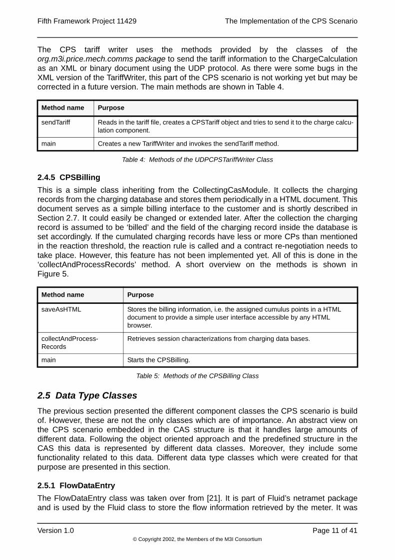
The CPS tariff writer uses the methods provided by the classes of theorg.m3i.price.mech.comms package to send the tariff information to the ChargeCalculationas an XML or binary document using the UDP protocol. As there were some bugs in theXML version of the TariffWriter, this part of the CPS scenario is not working yet but may becorrected in a future version. The main methods are shown in Table 4.
2.4.5 CPSBilling
This is a simple class inheriting from the CollectingCasModule. It collects the chargingrecords from the charging database and stores them periodically in a HTML document. Thisdocument serves as a simple billing interface to the customer and is shortly described inSection 2.7. It could easily be changed or extended later. After the collection the chargingrecord is assumed to be ‘billed’ and the field of the charging record inside the database isset accordingly. If the cumulated charging records have less or more CPs than mentionedin the reaction threshold, the reaction rule is called and a contract re-negotiation needs totake place. However, this feature has not been implemented yet. All of this is done in the‘collectAndProcessRecords’ method. A short overview on the methods is shown inFigure 5.
2.5 Data Type Classes
The previous section presented the different component classes the CPS scenario is buildof. However, these are not the only classes which are of importance. An abstract view onthe CPS scenario embedded in the CAS structure is that it handles large amounts ofdifferent data. Following the object oriented approach and the predefined structure in theCAS this data is represented by different data classes. Moreover, they include somefunctionality related to this data. Different data type classes which were created for thatpurpose are presented in this section.
2.5.1 FlowDataEntry
The FlowDataEntry class was taken over from [21]. It is part of Fluid’s netramet packageand is used by the Fluid class to store the flow information retrieved by the meter. It was
Method name Purpose
sendTariff Reads in the tariff file, creates a CPSTariff object and tries to send it to the charge calcu-lation component.
main Creates a new TariffWriter and invokes the sendTariff method.
Table 4: Methods of the UDPCPSTariffWriter Class
Method name Purpose
saveAsHTML Stores the billing information, i.e. the assigned cumulus points in a HTML document to provide a simple user interface accessible by any HTML browser.
collectAndProcess-Records
Retrieves session characterizations from charging data bases.
main Starts the CPSBilling.
Table 5: Methods of the CPSBilling Class

The Implementation of the CPS Scenario Fifth Framework Project 11429
© Copyright 2002, the Members of the M3I Consortium
Page 12 of 41 Version 1.0
slightly extended to provide some additional information. Since CPSMediationRecordscontain almost the same information, these data fields are described in Section 2.5.2 moredetailed.
2.5.2 CPSMediationRecord
The CPSMediationRecord class extends the abstract class MediationRecord andimplements all the required methods. It is used by various component classes to create amediation record. Data fields describing the mediation record are shown in Table 6.
2.5.3 CPSCustomer
The CPSCustomer class has been created to provide the session information used in theCAS. It is used by the CPSConnector to append the necessary session information to themediation records. The session information of the current customers is compared with theactual flow information and then appended to those records. This class could easily be
Variable name Description
flowDataToOctets, flowDataFromOctets
Number of bytes for this flow since last query (for both directions)
flowDataToPDUs, flowDataFromPDUs
Number of packets for this flow since last query (for both directions)
flowDataToBandwidth, flowDataFromBandwidth
Average bandwidth for this flow (for both directions)
flowDataToECTPDUs, flowDataFromECTPDUs
ECN ECT packets (for both directions)
flowDataToCEPDUs, flowDataFromCEPDUs
ECN CE packets (for both directions)
flowDataDSCP Diffserv codepoint field of the IP header
flowDataSourcePeerAddress IP address of the source host
flowDataSourceTransAddress TCP/UDP port of the source host
flowDataDestPeerAddress IP address of the destination host
flowDataDestTransAddress TCP/UDP port of the destination host
isFirst First record of a session
isLast Last record of a session
customerId Customer number
contractId Contract number (used for the tariff)
serviceId Service number (reservated for later use)
sessionId Session counter
recordSource Hostname of the meter host
flowId Flow number provided by the meter
Table 6: Variables of the CPSMediationRecord Class

Fifth Framework Project 11429 The Implementation of the CPS Scenario
© Copyright 2002, the Members of the M3I Consortium
Version 1.0 Page 13 of 41
replaced later by the customer support component, which is not part of the CAS yet. The
methods of this class are shown in Table 7.
2.5.4 CPSSessionFragment
The CPSSessionFragment class contains mainly the same information as a mediationrecord. It extends the SessionFragment class and implements therefore the methodinitFromMediationRecord to initialize the attributes. It contains both the flow data and thesession information and is used by the accounting compontent to create a new record in theaccounting database.
2.5.5 CPSSessionCharacterisation
The CPSSessionCharacterization class collects all session fragments belonging to asession that have been pulled from the accounting database by the charge calculation. Itextends the SessionCharacterisation class and therefore implements theinitFromFragments method which calculates the total resource usage accumulating sessionfragments. This class is used by the charge calculation to create charging records. Themainly provided data fields are shown in Table 8. Fields providing ECN, DSCP and the likeneed to be added here in future according to the respective design.
2.5.6 CPSTariff
In the Cumulus Pricing Scheme, which is described in [7] more detailed, the user is notdirectly charged for usage, he just pays a flat rate fee. But there is a set of thresholds whichlimit the consumption for over- and also underusage. The user is given red or green pointsif her service usage exceeds a certain CP threshold value mentioned in the user contract.These cumulus points can also be accumulated over time. If they exceed a certain level,the reaction rule will be applied, e.g., the contract will be redefined. The CPSTariff classextends the Tariff class from the M3I project. It is used to carry the information about
Method name Purpose
sessionHasExpired Check if the current session for this customer has expired.
startFirstSession Start the session for the first time.
startNextSession Start the next session. The sessionStartTime is incremented by the sessionDura-tionTime.
Table 7: Methods of the CPSCustomer Class
Variable name Purpose
totalUpVolume,totalDownVolume
Total number of bytes for the session in either directions.
totalUpPackets,totalDownPackets
Total number of packets for the session in either directions.
averageUpBandwidth,averageDownBandwidth
Average bandwidth during the session in either directions.
Table 8: Variables of the CPSSessionCharacterisation Class

The Implementation of the CPS Scenario Fifth Framework Project 11429
© Copyright 2002, the Members of the M3I Consortium
Page 14 of 41 Version 1.0
predefined service contracts, threshold values and reaction rules. The charge calculationgets these informations from the UDPCPSTariffWriter component and uses it to charge forthe service usage. The main method that is provided to calculate the cumulus points isgetChargeAdvice which is invoked by the charge calculation. It compares the service usageover a session with the CP threshold values and assigns the appropriate cumulus points.
2.6 Data Flows
In the last two sections component type classes and data type classes used to implementthe CPS scenario in the CAS have been explained in detail. However, for a more clear viewabout what exactly happens in the implementation it is sometimes useful to have a closerand more specific look on data flows themselves. Therefore in this section it is recapitulatedwhere and how data is processed using the down-top approach. In Figure 3 this data flow isshown.
First of all, real traffic needs to be flowing through a physical network interface. There areseveral possibilities to achieve this as described later in Section 4.1. In the CPSexperiments DBS is used to generate traffic as already mentioned above. The generatedtraffic is then measured by NeTraMet which combines the traffic, i.e. the single packets intoflows based on rules that have been provided by NeMaC. Then, periodically, using theSNMPv2 protocol the meter reader, i.e. Fluid reads out traffic flows which are currentlypresent on the meter host. This encompasses, e.g., the number of accumulated bytes,packets or even ECN bits for a flow specified by its source and destination address. Sincedifferential numbers instead of accumulated numbers need to be calculated for furtherprocessing, the flow data is then transformed by the CPSMediation class into mediationrecords using the difference of two consecutive flow entries. Until here the data processingis completely independent from the rest of the application, since the CPSMediation class is
NeTraMet
Fluid
CPSMediation
CPSMediationRecord
Accounting
ChargeCalculation
CPSBilling
CPSSessionFragment
CPSSessionCharacterisation
CPSTariff
CPSConnectorCPSCustomer
DBS
FlowDataEntry
SNMPv2
Traffic
Session Data
e.g. ContractId
ServiceId, UserId
Tariff Data
e.g. Thresholds
Flow Data
e.g. Volume,
Bandwidth
Figure 3: Data Flow in the CPS Scenario

Fifth Framework Project 11429 The Implementation of the CPS Scenario
© Copyright 2002, the Members of the M3I Consortium
Version 1.0 Page 15 of 41
running as a thread on its own. However, it must be considered that the internal data bufferof the CPSMediation class is not infinite and can therefore overflow if the data is notcollected continuously.
The CPSConnector class fetches mediation records from the CPSMediation componentand appends the session information to those records that belong to a certain customer.Records for which there are no appropriate owners are discarded. The CPSConnectorclass can also generate mediation records itself. For instance, a dummy record isgenerated to terminate a session if it exceeds the session duration. In the Accounting classrecords provided by the CPSConnector are transformed into CPSSessionFragments andstored in the accounting database. From there, the charge calculation collects all sessionfragments belonging to a session that has a start point and an end point and creates aCPSSessionCharacterisation. Moreover it calculates the charge for the service usageduring that session applying the CPS tariff used for the appropriate service contract. Theresult is stored in the charging database, from where the CPSBilling class gets the billinginformation and creates a CPS billing interface using them.
2.7 User Interface
As described above, a simple user interface is created by the CPSBilling class tocommunicate the charge to the customer in terms of assigned cumulus points for everysession and accumulated over time. The CPSBilling collects charging records from thecharging database and stores them periodically in a HTML document. This documentserves as a simple interface to the customer and can easily be represented in a HTMLbrowser as shown in Figure 4. It could simply be changed or extended in future.
2.8 Connection Setup
Apart from the above described implementation components, there has also been someeffort on the design and implementation of a user interface for the connection setup, i.e. thesetup of a user session. Since this part was not used in the current CPS experiments, it wasplaced in the appendix, Section 11.
Simple CPS Billing Interface
StorageTimeStamp AverageUpBandwidth CPs Total CPs
2002-01-21 15:47:04.0 197595.7675448029 1
2002-01-21 15:47:34.0 185428.48754475053 1
2002-01-21 15:48:14.0 191021.6035427978 2
2002-01-21 15:48:54.0 148503.2971595294 0
2002-01-21 15:49:24.0 187590.54303988442 0
2002-01-21 15:50:04.0 152440.97013856962 -2
2002-01-21 15:50:35.0 204693.99932172845 0
2002-01-21 15:51:15.0 196400.47806267627 1
2002-01-21 15:51:55.0 145766.50656698222 -1
2002-01-21 15:52:25.0 219921.79398807883 1
2002-01-21 15:53:05.0 211564.9615473468 3Figure 4: CPS User Interface

The Implementation of the CPS Scenario Fifth Framework Project 11429
© Copyright 2002, the Members of the M3I Consortium
Page 16 of 41 Version 1.0
3 Networking EnvironmentThe develompent and testing of software for the M3I project and especially the CPSimplementation is supported by a small testnetwork. The following section aims to give asmall and understandable overview of the applied computer infrastructure.
3.1 Overview Testbed
An overview on the testbed is given in Figure 5. Actually the test network consists of fivePCs and a Solaris workstation. Three PCs are used as routers (RA, RB and RC2) and theyare enabled for DiffServ using the AltQ software. The remaining PCs (HA, HB3) and theSolaris workstation (HC) are used as normal hosts, whereas each one provides two IP-interfaces, i.e. two IP-addresses for the test-experiments, so that a virtual net of six hostsand three routers can be simulated, that span together totally six subnets. The existence oftwo IP-addresses per host leads also to the routing policy of this testbed. Traffic forwardingto a destination interface ending with 1 is specified clockwise and traffic to the 2counterclockwise, respectively.
2.RA, RB and RC stand for router A, B and C respectively.3.HA, HB and HC stand for host A, B and C respectively.

Fifth Framework Project 11429 The Implementation of the CPS Scenario
© Copyright 2002, the Members of the M3I Consortium
Version 1.0 Page 17 of 41
3.2 DiffServ Environment
As mentioned above the three routers are capable to handle traffic according to the DiffServmechanisms. This is achieved by using AltQ which is available for FreeBSD, the operatingsystem currently installed on these routers. A detailed description of the AltQ configurationis not given in this document, as these DiffServ mechanisms have not yet been consideredin detail for running experiments with CPS. However, experiments reading out the DiffServcodepoint have been successful, as both NeTraMet and the CPS implementation arecapable of handling this data field. On the other hand, no problems have been encounteredyet in charging for traffic of different levels of service classes.
3.3 Component Location
This section provides a detailed overview on various components of the test network andthe CPS scenario described in Section 2 and shows where they are located in the networkto perform the experiments described later. As already mentioned, most of the componentsof the CAS and the CPS implementation can be distributed when it is necessary to achieve
RA RB
RC
HA1
HA2
192.168.5.1
192.168.5.0/29 192.168.4.0/29
192.168.3.0/29
192.168.5.2 192.168.4.2
192.168.4.1
192.168.3.2192.168.3.1 192.168.2.0/29192.168.1.0/29
HB2
HB1192.168.1.2
192.168.1.1
192.168.2.1
192.168.2.2
192.168.2.3192.168.1.3
HC1
HC2 HC3
129.132.57.32/27
129.132.57.37
129.132.57.33
129.132.57.34
RA
HA1
192.168.4.0/29
Router
Host
Subnet
Legend
Figure 5: Overview on the Testbed used for the CPS Experiments

The Implementation of the CPS Scenario Fifth Framework Project 11429
© Copyright 2002, the Members of the M3I Consortium
Page 18 of 41 Version 1.0
a better performance. However, in the CPS experiments the option of, e.g., distributing theCAS is not used to keep the setup simple. Therefore most of the components are locatedon one machine, i.e. router RC and only the traffic measurements are performed on othermachines, i.e. router RA or RB. The location of these various components is shown in
Table 9.
4 Experiment SetupIn this section the set up of a real environment to run the following experiments with theCPS scenario is described in step-by-step mode. First a closer look into possibilities forgenerating the necessary traffic is taken. Secondly, it is shown how all testbed componentsare configured and in which sequence they need to be started to run experiments.
4.1 Traffic Generation
There exist many possibilities to generate network traffic. In search of a good tool for trafficgeneration quite a few options were evaluated. First, requirements are presented that thetool should be able to meet. Then an overview is given on various tools that have beenevaluated for such purpose. Finally, the traffic pattern is discussed that should be generatedby the tool.
4.1.1 Requirements
First of all, within a real environment, traffic flowing through physical network interfaces andreal protocol stacks needed to be generated. So rather than a tool for network simulation, asoftware needed to be found that generates real traffic flowing through physicallydistributed components. Since it was important to have a traffic pattern which is changingover time, in order to cause the generation of cumulus points, the traffic generator shouldfurther be able to generate varying traffic, reading the data, e.g., out of a configuration file.Finally, both TCP and UDP traffic should be generated by the tool.
4.1.2 Tools Evaluation
Three different traffic generators were evaluated to find out which one fulfills best the aboverequirements. An overview on the evaluation is shown in Table 10.
RA RB RC HA HB HC
OS FreeBSD 4.2
FreeBSD 4.2
FreeBSD 4.2
FreeBSD 4.1.1
FreeBSD 4.2
SunOS 5.7
DiffServ AltQ AltQ AltQ
Java jdk1.2.2 jdk1.2.2 jdk1.2.2 jdk1.1.8 jdk1.1.8 jdk1.2.2
Database mySQL
Traffic Meter NeTraMet NeTraMet NeMaC
Traffic Genera-tor
dbsc dbsd dbsd
Table 9: Development Environment and Component Location on the Testbed
Fifth Framework Project 11429 The Implementation of the CPS Scenario
© Copyright 2002, the Members of the M3I Consortium
Version 1.0 Page 19 of 41
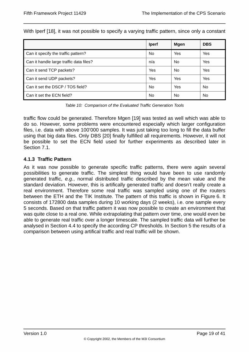
With Iperf [18], it was not possible to specify a varying traffic pattern, since only a constant
traffic flow could be generated. Therefore Mgen [19] was tested as well which was able todo so. However, some problems were encountered especially which larger configurationfiles, i.e. data with above 100’000 samples. It was just taking too long to fill the data bufferusing that big data files. Only DBS [20] finally fulfilled all requirements. However, it will notbe possible to set the ECN field used for further experiments as described later inSection 7.1.
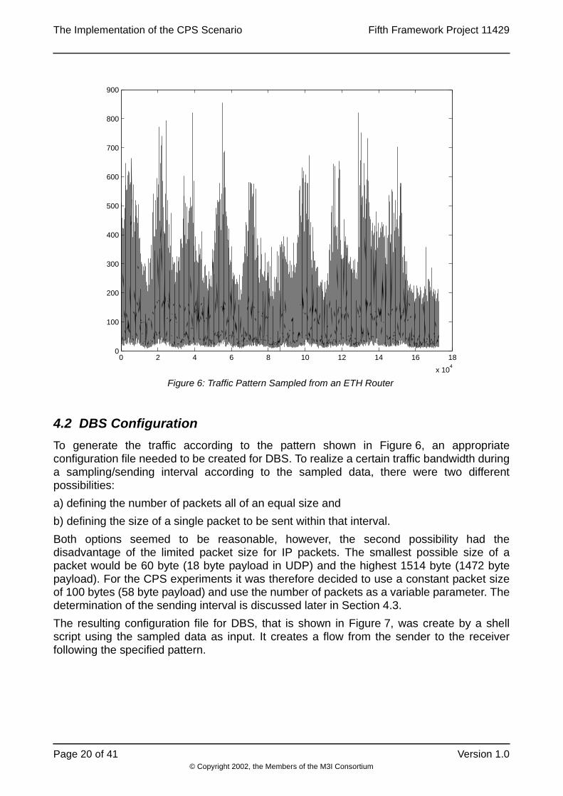
4.1.3 Traffic Pattern
As it was now possible to generate specific traffic patterns, there were again severalpossibilities to generate traffic. The simplest thing would have been to use randomlygenerated traffic, e.g., normal distributed traffic described by the mean value and thestandard deviation. However, this is artifically generated traffic and doesn’t really create areal environment. Therefore some real traffic was sampled using one of the routersbetween the ETH and the TIK Institute. The pattern of this traffic is shown in Figure 6. Itconsists of 172800 data samples during 10 working days (2 weeks), i.e. one sample every5 seconds. Based on that traffic pattern it was now possible to create an environment thatwas quite close to a real one. While extrapolating that pattern over time, one would even beable to generate real traffic over a longer timescale. The sampled traffic data will further beanalysed in Section 4.4 to specify the according CP thresholds. In Section 5 the results of acomparison between using artifical traffic and real traffic will be shown.
Iperf Mgen DBS
Can it specify the traffic pattern? No Yes Yes
Can it handle large traffic data files? n/a No Yes
Can it send TCP packets? Yes No Yes
Can it send UDP packets? Yes Yes Yes
Can it set the DSCP / TOS field? No Yes No
Can it set the ECN field? No No No
Table 10: Comparison of the Evaluated Traffic Generation Tools
The Implementation of the CPS Scenario Fifth Framework Project 11429
© Copyright 2002, the Members of the M3I Consortium
Page 20 of 41 Version 1.0
4.2 DBS Configuration
To generate the traffic according to the pattern shown in Figure 6, an appropriateconfiguration file needed to be created for DBS. To realize a certain traffic bandwidth duringa sampling/sending interval according to the sampled data, there were two differentpossibilities:
a) defining the number of packets all of an equal size and
b) defining the size of a single packet to be sent within that interval.
Both options seemed to be reasonable, however, the second possibility had thedisadvantage of the limited packet size for IP packets. The smallest possible size of apacket would be 60 byte (18 byte payload in UDP) and the highest 1514 byte (1472 bytepayload). For the CPS experiments it was therefore decided to use a constant packet sizeof 100 bytes (58 byte payload) and use the number of packets as a variable parameter. Thedetermination of the sending interval is discussed later in Section 4.3.
The resulting configuration file for DBS, that is shown in Figure 7, was create by a shellscript using the sampled data as input. It creates a flow from the sender to the receiverfollowing the specified pattern.
0 2 4 6 8 10 12 14 16 18
x 104
0
100
200
300
400
500
600
700
800
900
Figure 6: Traffic Pattern Sampled from an ETH Router

Fifth Framework Project 11429 The Implementation of the CPS Scenario
© Copyright 2002, the Members of the M3I Consortium
Version 1.0 Page 21 of 41
4.3 Experiment Parameters and Timescales
It is important to consider that since CPS is a charging mechanism on the longer timescalethe experiments with this scenario would also absorb a long time. Therefore it is more
FullnameParameter
Description
Sending Inter-val
TSn Time interval of sending the next packet(s) by the traffic generator, i.e. the granularity of the traffic. Within this interval the bandwidth of the traffic is con-stant.
Sampling Inter-val
TSm Time interval of sampling the traffic data by the meter, i.e. the granularity of the meter.
Session Dura-tion / Charging Interval
TS Duration of a session, i.e. the time interval of charging for a session.
Contract Dura-tion / Experi-ment Duration
TC Duration of the contract period, i.e. the duration of the whole experiment.
Thresholds Thresholds determined in the tariff for assigning the cumulus points.
Experiment Timefactor
f Factor between the real timescale and the experiment timescale.
Accounting Fre-quency
TA Time interval of collecting mediation records used for the Accounting class in the CAS.
Charging Fre-quency
TCh Time interval of collecting session fragments used for the ChargeCalculation class in the CAS.
BillingFrequency
TB Time interval of collecting session characterisations used for the CPSBilling class.
Table 11: Parameters used for the CPS Experiments
{sender {
hostname = HA2;port = 12300;mem_align = 58;pattern {3074.000, 58, 0.05, 0.0;6844.000, 58, 0.05, 0.0;...1160.00, 58, 0.05, 0.0;}
}receiver {
hostname = HB1;port = 12301;mem_align = 58;pattern { 58, 58, 0.05, 0.0}
}
Figure 7: DBS Configuration File for the Traffic Generation
θn

The Implementation of the CPS Scenario Fifth Framework Project 11429
© Copyright 2002, the Members of the M3I Consortium
Page 22 of 41 Version 1.0
convenient to scale the time a little bit. When talking about scaling the time it is important tonote that the traffic volume needs also to be scaled, since it is not possible to just sendingthe same traffic volume in a shorter time because of the limited physical bandwidth.However, it is no problem to scale the volume, if the granularity of the traffic load can bekept the same. Using the granularity described in the previous section, i.e. 100 bytes perpacket, was suitable for the experiments.
The time parameters in the CPS scenario that are subject to be scaled are listed inTable 11. It is importent to note that the time cannot be scaled to much. Obviously thebottleneck was between the flow meter and the meter reader, i.e. the sampling interval TSmwhich could not be made smaller than around 0.5 seconds. So to achieve the samegranularity as the generated traffic, i.e. 5 seconds, the highest possible timefactor f wouldbe 10. This limitation is definitely depending on the delay between the meter and thereader. Therefore better results could be achieved if the meter would be located on thesame host as the reader. However, this was only a problem for running the experiments butnot for the CPS scenario in a whole. Therefore it was not worth to further increase thisperformance, although there would be possibilities to achieve this, e.g., through pipelining,i.e. asynchronous requests. In the experiments the timefactor was just increased byresampling the traffic measurements, i.e. loosing a little bit of granularity. The actualtimescales used for the experiments are shown in Section 5.
4.4 Threshold Calculation
A major effort was the choice of reasonable values for the CP thresholds. [8] is a goodtutorial on how to choose these thresholds based on the mean value and the standarddeviation of the traffic. However, it is assumed that the traffic is close to normal distribution.Figure 8 shows the probability function of the sampled traffic pattern of Figure 6. Obviouslythe assuption of normal distribution is no longer valid, at least for this level of granularity, i.e.averaged values over 5 seconds. Only for average values over a longer timescale, theprobability function might migrate towards normal distribution, however, the procedure fornon-normal distribution described in [29] is better applicable. According to that, the absolutethresholds can be calculated as follows.

Fifth Framework Project 11429 The Implementation of the CPS Scenario
© Copyright 2002, the Members of the M3I Consortium
Version 1.0 Page 23 of 41
Assume that the traffic is described by the probability density function and the
respective discrete probability distribution .
This distribution can be calculated by numerical integration of the respective histogram. Let
describe the probability that the measured traffic is within the interval . This
yields absolute thresholds where describes the inverse probability
distribution function. The so calculated absolute thresholds are shown in Table 12. The
respective mean is 90.7 [kbits/s].
90 % 79.0 102.4
99 % 69.1 112.3
Table 12: Calcualted Thresholds for the Sampled Traffic
0 100 200 300 400 500 600 700 800 9000
.002
.004
.006
.008
0.01
.012
.014
.016
.018
Figure 8: Probability Density Function of the Sampled Traffic Pattern
f x( )
F x( ) f y( ) yd
x
∫ Prob measured traffic x≤{ }= =
ηn ϑ n– ϑn;[ ]
ϑ n± F1– 1 ηn±
2--------------- = F
1–
η ϑ n– ϑn

The Implementation of the CPS Scenario Fifth Framework Project 11429
© Copyright 2002, the Members of the M3I Consortium
Page 24 of 41 Version 1.0
4.5 Experiment Invocation Process (Running the Scenario)
This section describes all the steps for running the CPS scenario. First, all componentsneed to be properly configured. Then the scenario needs to be started in the correctsequence. To configure the components, the according configuration files have to beadapted to the current experiment, i.e. the time parameters need to be set to reasonablevalues and other variables must be configured correctly.
CAS Configuration: The provided configuration file acc.cfg.CPSdemo for the Accountingand cc.cfg.CPSdemo for the ChargeCalculation need to be adapted. This especiallyincludees setting the right location of the databases, the input frequencies and the data typeclasses. In addition to that the URL of the connection configuration file needs to beindicated in acc.cfg.CPSdemo.
CPS Configuration: For the connector class the conn.cfg.CPSdemo needs to be adaped.An example is shown in Figure 9. PollingFrequency is the periodtime in seconds of readingout data from the meter. More than one meter host can be configured.
The file tariff.cfg is used to configure the CPSTariff class. N is the number of thresholds oneither side of the target mean value. M is the number of contracts provided. The bandwidththresholds are measured in bytes/s. An example of the tariff file is shown in Figure 10.
Finally, the bil.cfg.CPSdemo needs to be configured correctly to setup the connection to thecharging database used by the CPSBilling component and the according input frequency.
NeTraMet Configuration: To setup NeTraMet one needs to create an appropriate srl-file,e.g., <hostname>.testbed.srl shown in Figure 11 and compile it into a rulefile using the srlcompiler which is included in [26]. After that NeMaC is invoked to send this file to NeTraMetas described in the next section.
[org.m3i.mediation.Connector]class=org.m3i.examples.ethz.CPSdemo.CPSConnector
[org.m3i.examples.ethz.CPSdemo.CPSConnector settings]MeterHost=RAMeterHost=RBPollingFrequency=0.5
[org.m3i.examples.ethz.CPSdemo.CPSConnector default attributes]
Figure 9: Connector Configuration File used in the CPS scenario
N 2 M 5contractId 4 160000 170000 181431 190000 200000contractId 1 160000 170000 181431 190000 200000contractId 2 160000 170000 181431 190000 200000contractId 3 160000 170000 181431 190000 200000contractId 0 160000 170000 181431 190000 200000
Figure 10: Tariff Configuration File used in the CPS scenario

Fifth Framework Project 11429 The Implementation of the CPS Scenario
© Copyright 2002, the Members of the M3I Consortium
Version 1.0 Page 25 of 41
Database Setup: Before all the components can be started, the database has to becreated used by the CAS for storing the accounting and charging records. The filecas_26_06_01.sql contains to most actual version of the database structure compatiblewith the current CAS version.
Component Invocation Procedure: Now the components can be started in the correctsequence. For that purpose a shell script cpsrun.sh has been written that makes it easier tostart everything. Make sure that the path, classpath and all other variables are set correctlyfor your environment. The script opens a new terminal for every process. First NeTraMetneeds to be started on the meter host and configured by NeMaC. Then the Accountingcomponent can be invoked to start the measurements and data storage. Now the traffic canbe generated. Therefore two DBS daemons, i.e. dbsd, have to be started, a sender and areceiver according to the DBS configuration file, and one controller, i.e. dbsc. The chargecalculation and the billing component can be started at any point of this procedure. All theprovided options of the script are shown in Figure 12. The CPSManager and theCSDaemon components as well as the NeMaCServer are not used in the CPSexperiments. For a simpler traffic pattern the dummy traffic components can also be started,i.e. Iperf clients and servers.
# NeMaC srl file RA.testbed.srl## @hausheer
SET 2;FORMATFlowRuleSet FlowIndex SourcePeerType SourceTransTypeSourcePeerAddress DestPeerAddressSourceTransAddress DestTransAddressToPDUs FromPDUs ToOctets FromOctetsFirstTime LastTime DSCodePoint;
if SourcePeerType == IP save;else ignore;
if SourceTransType == tcp || SourceTransType == udp {
save SourcePeerType; save SourceTransType; save SourcePeerAddress; save SourceTransAddress; save DestPeerAddress; save DestTransAddress; save DSCodePoint;
count;}
Figure 11: NeMaC SRL File used in the CPS Scenario

The Implementation of the CPS Scenario Fifth Framework Project 11429
© Copyright 2002, the Members of the M3I Consortium
Page 26 of 41 Version 1.0
5 Experiment ResultsThis section discusses various detailed experiments that have been run on the testbedusing the CPS implementation described above. It is important to note that there are manydifferent possibilities to run these experiments and it is important to indicate initially whichkind of results are to be shown. Potential issues include:
1. Show the performance of the CPS implementation by, e.g., monitoring the usage ofmemory, cpu or network bandwidth, addressing the potential bottlenecks and limitationsand show how scalable the system is,
2. Comparing the output of the CPS pricing mechanism, i.e. the assignment of cumuluspoints using different kinds of traffic patterns as input,
3. Comparing CPS while varying the various experiment parameters and timescalesshown in Table 11 or
4. Comparing CPS with other pricing mechanisms, e.g., ECN based pricing.
Since the implementation determines a prototype and has not been optimized for maximumscalability and performance, it is not useful with respect to topic (1.) to investigate on allperformance issues at the moment and this will be part of future work. However, since CPSdoes not count on every single packet, but rather measures traffic only every now and then,it can be stated that CPS is able to produce valuable results without too much effort in termsof accounting and, therefore, the overall system performance is of less relevance on thewhole.
bash-2.04$ ./cpsrun.shusage: cpsrun.sh nn: 1: Running CPSManager on Host HA1 2: Running CPSManager on Host HB1
3: Running CSDaemon on Edge Router RA 4: Running CSDaemon on Edge Router RB
5: Running NeTraMet on RA 6: Running NeTraMet on RB 7: Running NeMaCServer on Charging Host (RC)
8: Running the Charge Calculation (on RC) 9: Running the Billing (on RC)10: Running Tariff Writer (on RC) => not working yet!11: Running Accounting (on RC)
12: Running Dummy Traffic Server on HA113: Running Dummy Traffic Server on HB114: Running Dummy Traffic Client on HA115: Running Dummy Traffic Client on HB1
16: Running NeMaC for RA on RC17: Running NeMaC for RB on RC
18: Running DBS Controller on RC19: Running DBS Daemon on HA2 (Sender)20: Running DBS Daemon on HB1 (Receiver)
Figure 12: CPS Run Script Options

Fifth Framework Project 11429 The Implementation of the CPS Scenario
© Copyright 2002, the Members of the M3I Consortium
Version 1.0 Page 27 of 41
On the other hand, topic (2.) is of high relevance and some of these results will bepresented in Section 5.1. Also topic (3.) was interesting to look at and a few examples ofthose experiments are shown later in Section 5.2.
For a comparing statement on the CPS concept and its detailed behavior, however, it wouldbe necessary to compare it with other scenarios, e.g., with a pricing based on ECN asmentioned in topic (4.). Unfortunately, ECN is still a quite new technology with hardly anysupport in terms of available implementations. Therefore, it was yet not possible to run CPSand ECN experiments in parallel. But it is still an important motivation to do this in thefuture. Some of the most important remaining steps are discussed in Section 7.1.
5.1 The Relevance of the Traffic Pattern
As already discussed above in Section 4.1.3 the traffic pattern used as input for the CPSscenario is of high importance. While it does not make sence to run experiments based ona constant traffic flow except for measuring performance related issues, only varying trafficpatterns were compared. In this experiment, both artificial traffic based on random numbersand real traffic following a special traffic pattern was generated. The real traffic wassampled from a real router as described previously in Section 4.1.3 and shown in Figure 6.The artificial traffic was generated based on numbers chosen from a normal distribution.
Table 13 shows the exact parameters used in these experiments. The mean value andstandard deviation of the sampled real traffic was calculated and the same parameterswere used to generate the random numbers for the artifical traffic. The thresholds werecalculated using the standard deviation of the real traffic averaged over the charginginterval. Also the same thresholds were used for both experiments. The charging intervalwas intentionally set to a small value, i.e. 1 hour.
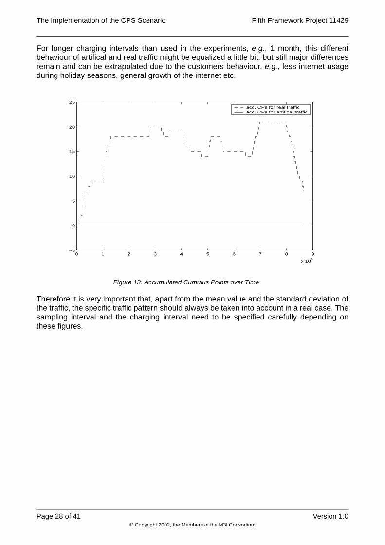
In Figure 13 the accumulated cumulus points over time are shown for both experiments.
While the artifical traffic doesn’t effect any cumulus points, the curve for the real trafficobviously follows the actual situation, i.e. arises in times of a higher usage and falls in timesof lower usage. The reason why artifical traffic leads to such stable output is the absence ofa pattern that follows the real internet usage, which is usually higher during the day andlower during the night. This is of course dependent on where the traffic is measured. Thetraffic pattern for a private customer is usually different from the pattern of a businesscustomer or even the pattern between two internet providers.
Parameter Value (in real time)
Sampling Interval TSn 5 s
Charging Interval TS 3’600 s (1h)
Experiment Duration TC 864’000 s (10 d)
Mean value of the traffic 90.7 kbit/s
Standard deviation of the traffic 75.3 kbit/s
Standard deviation of the traffic average over TS 33.7 kbit/s
Thresholds [9.9 46.9 134.5 171.6] kbit/s
Table 13: Parameters used in Experiment 1
The Implementation of the CPS Scenario Fifth Framework Project 11429
© Copyright 2002, the Members of the M3I Consortium
Page 28 of 41 Version 1.0
For longer charging intervals than used in the experiments, e.g., 1 month, this differentbehaviour of artifical and real traffic might be equalized a little bit, but still major differencesremain and can be extrapolated due to the customers behaviour, e.g., less internet usageduring holiday seasons, general growth of the internet etc.
Therefore it is very important that, apart from the mean value and the standard deviation ofthe traffic, the specific traffic pattern should always be taken into account in a real case. Thesampling interval and the charging interval need to be specified carefully depending onthese figures.
0 1 2 3 4 5 6 7 8 9
x 105
−5
0
5
10
15
20
25acc. CPs for real trafficacc. CPs for artifical traffic
Figure 13: Accumulated Cumulus Points over Time

Fifth Framework Project 11429 The Implementation of the CPS Scenario
© Copyright 2002, the Members of the M3I Consortium
Version 1.0 Page 29 of 41
5.2 Parameter Tuning
There are several parameters that can be varyied as presented above in Section 4.3. Forthe following experiments the parameters were specified as shown in Table 14.
The experiment timefactor f, the sending interval TSn and the experiment duration TC werenot changed during these experiments. For the parameters accounting frequency TA,charging frequency TCh and billing frequency TB suitable values were chosen. Theyshouldn’t be to small for performance reasons and also not too large, i.e. at least smallerthan the charging interval. The sampling interval was also not varyied during theseexperiments, as these results were already shown in [30]. Therefore the only two remainingdegrees of freedom that were varyied are the charging intervals TS and the CPSthresholds. These appropriate results were described in Section 5.2.1 and Section 5.2.2,respectively.
5.2.1 Varying the Charging Interval
In Figure 14 the accumulated cumulus points for the different experiments using a varyiedcharging interval TS were shown. It is obvious that for a smaller charging interval theresulting curve is more “unstable”, i.e. follows the original traffic pattern.
Parameter Real Time Experiment Time
f 1 1/100
TSn 5 s 50 ms
TSm 50 s 0.5 s
TC 20 d = 1728000 s 4.8 h = 17280 s
TA 8.33 min = 500 s 5 s
TCh 8.33 min = 500 s 5 s
TB 33.33 min = 2000 s 20 s
Table 14: Parameter Settings in Experiment 1

The Implementation of the CPS Scenario Fifth Framework Project 11429
© Copyright 2002, the Members of the M3I Consortium
Page 30 of 41 Version 1.0
5.2.2 Varying the CPS Thresholds
For varyied CPS thresholds a similar behaviour can be observed. Figure 15 shows theappropriate curves for different thresholds. The thresholds were calculated using theaverages over different durations as mentioned in the legend. For smaller averages thethresholds become larger, due to a higher signal variance. The accumulated cumuluspoints therefore become “unstable” for higher thresholds.
0 50 100 150 200 250
0
5
10
15
20
25T
s = 1 h
Ts = 3 h
Ts = 6 h
Ts = 12 h
Figure 14: Accumulated Cumulus Points with Changing ChargingInterval

Fifth Framework Project 11429 The Implementation of the CPS Scenario
© Copyright 2002, the Members of the M3I Consortium
Version 1.0 Page 31 of 41
6 Summary and ConclusionsThe design and prototypical implementation of the CPS scenario with the CAS of the M3Iproject revealed that CPS could quite simply be adapted to the structure of the CAScomponents. Due to its modular design and the simplicity of the CPS concept it waspossible to create together a highly scalable and configurable traffic charging scenario, asall components components can easily be distributed and the traffic sampling and chargingintervals can be varied. Since the customer support component was not yet implemented inthe CAS, it was necessary to create a CPSCustomer class that provides the sessioninformation which is important in the CPS scenario. However, this class could easily bereplaced, when the customer support component will be added to the CAS.
The experiments showed that the implementation code could sucessfully be tested on aFreeBSD / Solaris testbed and even other platforms might be used due to the usage ofportable Java code.
It was hard to find a suitable traffic generator to run the simulation experiments. But finally,the experiments performed verified the feasibility of the CPS concept for a real environmentand reached a good performance. The experiments showed the different behaviours of theCPS mechanism using varyied technical parameters. However, for further comparisons itwould be necessary to run further experiments and compare them with other pricingmechanisms, e.g., ECN-based pricing.
0 50 100 150 200 250−5
0
5
10
15
20
25
30
35
40ave. over 1 dave. over 1 have. over 1 min
Figure 15: Accumulated Cumulus Points with Changing Thresholds

The Implementation of the CPS Scenario Fifth Framework Project 11429
© Copyright 2002, the Members of the M3I Consortium
Page 32 of 41 Version 1.0
7 Future Work
7.1 Comparison of CPS with ECN
The various experiments that have been performed showed that CPS pricing is highlyscalable in terms of the accounting effort with only few waste on the precision ofmeasurements. However, for a better statement about the technical effort, performance andprecision CPS needs to be compared with other scenarios, e.g., pricing based on ECN.Hence our motivation is to compare CPS and ECN on a technical, functional andeconomical level in detail and based on a real environment.
It is not trivial though to define a test case in order to compare CPS and ECN technically.On the one hand it is difficult to avoid the problem of comparing apples and oranges. ECNpricing is based on charges in the shorter time scale, whereas CPS charges on a longertimescale. Other than in the ECN scenario, where a user agent makes the decisions onbehalf of the user, in CPS a real human user controls the traffic based on the price.Therefore it is necessary to build a user model in order to simulate the reaction of the useron the price.
On the other hand, as ECN is still a quite new technology, hardly any implementationssupport ECN today. Altq supports ECN but only for experimental use. However, the problemstill remains, that ECN marks are set upon a artificially congested link. Among theevaluated traffic generators, e.g., DBS, Mgen and Iperf, there was none that supportssetting the ECN bit in addition to the other requirements. Also NeTraMet that was used forthe flow measurements doesn’t support ECN in its current official version.
For all the above reasons it was decided to wait for more ECN-”enabled” tools in order tosetup a realistic test environment to run the comparison experiments.
8 Reference[1] R. Andreassen (Edt.): Requirements Specifications, Part I Reference Model; M3I
Deliverable 1; Version 7, July 6, 2000.
[2] B. Briscoe (Edt.): Architecture, Part I Primitives & Compositions; M3I Deliverable 2;Version 1, July 7, 2000.
[3] S.A. Cotton (edt.): Network Data Management – Usage (NDM-U) for IP-Based Ser-vices; IPDR Specification Version 1.1, June 2000.
[4] ETSI: Internet Protocol (IP) based Networks; Parameters and Mechanisms for Charg-ing; ETSI TR 101 734 V.1.1.1, Sophia Antipolis, France, September 1999.
[5] TU-T Q.825: Specification of TMN Applications at the Q3 Interface: Call Detail Record-ing; Recommendation Q.825, Geneva Switzerland, 1998.
[6] M. Karsten (Edt.): Pricing Mechanisms Design (PM); M3I Deliverable 3, Version 1.0,June 30, 2000.
[7] P. Reichl, P. Flury, J. Gerke, B. Stiller: How to Overcome the Feasibility Problem forTariffing Internet Services: The Cumulus Pricing Scheme; IEEE International Confer-ence on Communications, Helsinki, Finland, June 11-15, 2001.
[8] P. Reichl, B. Stiller: Notes on Cumulus Pricing and Time-scale Aspects of Internet TariffDesign; Computer Engineering and Networks Laboratory, ETH Zürich, Switzerland,TIK Report No. 97, November 2000.

Fifth Framework Project 11429 The Implementation of the CPS Scenario
© Copyright 2002, the Members of the M3I Consortium
Version 1.0 Page 33 of 41
[9] P. Reichl, B. Stiller (Edt.): ISP Cost Model (ICOMO) Design; M3I Deliverable 8; Ver-sion 2.0, December 18, 2000.
[10] B. Stiller (Edt.): Charging and Accounting (CAS) Design; M3I Deliverable 4,Version 1.01, July 1, 2000.
[11] B. Stiller, G. Fankhauser, N. Weiler, B. Plattner: Charging and Accounting for Inte-grated Internet Services - State of the Art, Problems, and Trends; The Internet Summit(INET’98), Geneva, Switzerland, July 21-24, 1998, Session Commerce and Finance,Track 3.
[12] B. Stiller, J. Gerke, P. Flury: Charging and Accounting System Design (CAS); M3IDeliverable 4, Version 1.01, July 7, 2000.
[13] B. Stiller, J. Gerke, P. Reichl, P. Flury: The Cumulus Pricing Scheme and its Integra-tion into a Generic and Modular Internet Charging System for Differentiated Services;Computer Engineering and Networks Laboratory, ETH Zürich, Switzerland, TIK ReportNo. 96, September 2000.
[14] B. Stiller, J. Gerke, P. Reichl, P. Flury: Management of Differentiated Services Usageby the Cumulus Pricing Scheme and a Generic Internet Charging System; IEEE/IFIPSymposium on Integrated Network Management (IM’2001), Seattle, Washington,U.S.A., May 14-17, 2001.
[15] B. Stiller, P. Reichl. J. Gerke, P. Flury: A Generic and Modular Internet Charging Sys-tem for Differentiated Services and a Seamless Integration of the Cumulus PricingScheme; Journal of Network and Systems Management, Vol. 3, No. 9, September2001.
[16] P. Flury, B. Stiller: Cumulus Pricing Scheme (CPS); M3I Deliverable 7.2, Version 1.0,December 30, 2000.
[17] B. Stiller, J. Gerke, H. Hasan, V. Darlagiannis, H. Daanen: CAS Implementation; M3IDeliverable 13, Version 1.1, July 20, 2001.
[18] A. Tirumala, J. Ferguson: Iperf, The TCP/UDP Bandwidth Measurement Tool, version1.2; available at URL http://dast.nlanr.net/Projects/Iperf/, May 2001.
[19] B. Adamson: The “Multi-Generator” (MGEN) Toolset, version 3.1; available at URLhttp://manimac.itd.nrl.navy.mil/MGEN/, August 1999.
[20] Y. Murayama, S. Yamaguchi: Distributed Benchmark System (DBS): A Powerful Toolfor TCP Performance Evaluations, version 1.1.5; available at URL http://www.kusa.ac.jp/~yukio-m/dbs/, November 1997.
[21] Siegfried Löffler: Fluid, A Java Interface to NeTraMet, version 1.10; available at URLhttp://www.mathematik.uni-stuttgart.de/~floeff/diplom/fluid/, August 1997.
[22] AdventNet Inc.: The Java SNMPv2 class library; available at URL http://www.advent-net.com/products/snmp/, September 2001.
[23] Sun Microsystems: Java (TM) 2 Platform, Standard Edition, version 1.2.2; available atURL http://java.sun.com/products/1.2/, January 2001.
[24] MySQL AB: MySQL, version 3.22.32; available at URL http://www.mysql.com/, Janu-ary 2001.
[25] The FreeBSD Project: FreeBSD, release 4.2; available at URL http://www.freebsd.org/, November 2000.
[26] N. Brownlee: Network Traffic Meter (NeTraMet) & NeTraMet Manager/Collector(NeMaC) version 4.3; available at URL http://www2.auckland.ac.nz/net/Accounting/ntm.Release.note.html, February 2001.
[27] N. Brownlee: Traffic Flow Measurement: Meter MIB, rfc2720; October 1999.
The Implementation of the CPS Scenario Fifth Framework Project 11429
© Copyright 2002, the Members of the M3I Consortium
Page 34 of 41 Version 1.0
[28] N. Brownlee, C. Mills, G. Ruth: Traffic Flow Measurement: Architecture, rfc722; Octo-ber 1999.
[29] P. Reichl: A Note on How to Choose Cumulus Thresholds; January 2002.
[30] P. Reichl, Burkhard Stiller: Edge Pricing in Space and Time: Theoretical and PracticalAspects of the Cumulus Pricing Scheme; 17th International Teletraffic Congress ITC2001.
9 AbbreviationsAAAC Authentication, Authorization, Accounting and ChargingCAS Charging and Accounting SystemCDR Call Detail RecordCH Confoederatio Helvetica, SwitzerlandCPS Cumulus Pricing SchemeD Germany, DeutschlandDB DatabaseDBS Distributed Benchmark SystemDiffServ Differentiated Services Internet ArchitectureDSCP Differentiated Services Code PointECN Explicit Congestion NotificationEPC Enterprise Policy ControlETH Eidgenössische Technische Hochschule ZürichGR Greece, HellasHTML HyperText Markup LanguageHP Hewlett PackardID IdentifierIPDR Internet Protocol Data RecordJDBC Java Database ConnectivityJDK Java Development KitN Norway, NorgeISP Internet Service ProviderM3I Market Managed Multi-service InternetQoS Quality-of-ServiceRSVP Resource Reservation ProtocolSNMP Simple Network Management ProtocolSQL Structured Query LanguageTCP Transmission Control ProtocolTIK Institut für Technische Informatik und KommunikationsnetzeTUD Technische Universität DarmstadtUDP User Datagram ProtocolUK United KingdomURL Uniform Resource Locator

Fifth Framework Project 11429 The Implementation of the CPS Scenario
© Copyright 2002, the Members of the M3I Consortium
Version 1.0 Page 35 of 41
WP Work PackageXML Extensible Markup Language
10 AcknowledgementsThe main parts of this document have been developed and written by David Hausheer,Jayesh Pandey, and Burkhard Stiller (ETH Zürich). Dedicated input on the calculation ofCPS thresholds in this experiment have been provided from Peter Reichl (FTW Wien).
The CPS scenario itself has been implemented by David Hausheer and Jayesh Pandey(ETH Zürich). Various helpful comments were received from Jan Gerke, Hasan, PascalKurtansky, and Burkhard Stiller (ETH Zürich).
Furthermore, many lively discussions within and outside the M3I project created input to thework. Apart from the people already mentioned above, the following people providedvaluable ideas and contributions: Kennedy Cheng and Marcelo Pias (BT) about ECN,Siegfried Löffler (Uni Stuttgart) with Fluid, Nevil Brownlee (University of Auckland) aboutNeTraMet, Hongguang Ma (ETH Zürich) on the traffic analysis, Karoly Farkas (ETH Zürich)with DBS, and Placi Flury about the testbed.
11 AppendixAs previously mentioned in Section 2.8, the design and implementation of the user interfacefor the connection setup is presented here. The following section addresses thecomponents of such an interface and connections to other parts like AA-Server andEnterprise Policy Control (EPC). After that a short description of the implementation isgiven.
11.1 Initialization Design (User End)
Figure 16 shows the design of a user connection setup.

The Implementation of the CPS Scenario Fifth Framework Project 11429
© Copyright 2002, the Members of the M3I Consortium
Page 36 of 41 Version 1.0
Description 1. Contract Negotiation: This is part of the setup phase where the contract is signed
between the user and the ISP. This can be done in two way, the customer gives hisrequirements or by using the Probe Phase.
2. The Enterprise Policy Control is used in the contract negotiation process. 3. The Contract Information is then stored in the Customer Database.4. This is information is send to the ‘AAA’ server to update its internal Database. This has
to include the following data:
Contract id, All the Customers and corresponding Users of the Contract. It must also contain some service information i.e. the Traffic classes allowed and the approximatemaximum bandwidth required.
The Contract may itseft contain more data, such as charging and pricing information.
Figure 16: Initialization Design (User End)

Fifth Framework Project 11429 The Implementation of the CPS Scenario
© Copyright 2002, the Members of the M3I Consortium
Version 1.0 Page 37 of 41
5. Initialization Phase: The user starts the CPS Connection Interface. The parameters forthe connection setup can be entered directly or loaded from a .connection file in theusers home directory. This may contain the following information: User Id, Customer Id,Contract Id, Source and Destination addresses (IP address + Port), Date and Servicerequirements.
6. Connection Request: The Connection Interface sends request to the Edge Router. Thisincludes the following information (currently BE:AF:EF correspond to numeric values asservice Id.):
7. The Connection Setup Deamon on the Edge Router passes the connection request toits cache. If the request matches some entry in the cache, the request is granted viapath 8 or else path 7a is taken. The ‘AAA’ server is passed the user connection request.The permission grant ( /deny) is passed to the cache via 7b. The Cache then updatesthe last entry.
8. The permission grant(/deny) information is passed to the Connection Setup Daemon.Internally the Connection Setup Daemon passes this information to the AdmissionControl which now can allow(/deny) the user traffic to flow.
9. The Permission Grant(/Deny) is send to the Connection Interface. The Connection cannow be used by the user.
10.The user connection request is send to the Metering Interface if permission has beengranted.
11. The EPC provides the Metering Interface with the sampling rate according to thepolicies setup for that particular contract. Now the user traffic which flows through theedge router is metered.
12.This is the user traffic flow. (NeTraMet copies the packets by entering into promiciousmode and then analyses the packet information.).
13.Represents the user data flow to the meter (just for representation)14.Represents the user data flow out of the meter.(just for representation)15.The data produced by the meter flows to the Mediation Interface. This would be in the
form of flow files. Snmp queries can be used to query the meter regarding the flowstatus.
16.Flow of the Policy Information from EPC to the Data Collection/ Accounting Unit.17.Flow of the Policy Information from EPC to the Charge Calculation Unit.18.The Customer Information is provided to the Charge Calculation Unit.19.The Feedback information from the Charging Database to update the EPC.20.EPC along with the feedback input from the billing database may cause the user to
renegotiate the Contract according to the Reaction Rule.
<contract_id>:= number
<user_id>:= number
<customer_id>:= number
<date>:= <hour>:<minutes>:<seconds>:<day>:<month>:<year>
<source>:=<IP_address>:<port>
<destination>:=<IP_address>:<port>
<service>:=<BE:AF:EF>:<bandwidth>
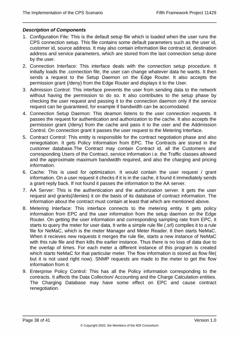
The Implementation of the CPS Scenario Fifth Framework Project 11429
© Copyright 2002, the Members of the M3I Consortium
Page 38 of 41 Version 1.0
Description of Components1. Configuration File: This is the default setup file which is loaded when the user runs the
CPS connection setup. This file contains some default parameters such as the user id,customer id, source address. It may also contain information like contract id, destinationaddress and service parameters, which are stored from the last connection setup doneby the user.
2. Connection Interface: This interface deals with the connection setup procedure. Itinitially loads the .connection file, the user can change whatever data he wants. It thensends a request to the Setup Daemon on the Edge Router. It also accepts thepermission grant (/deny) from the Edge Router and displays it to the User.
3. Admission Control: This interface prevents the user from sending data to the networkwithout having the permission to do so. It also contributes to the setup phase bychecking the user request and passing it to the connection daemon only if the servicerequest can be guaranteed, for example if bandwidth can be accomodated.
4. Connection Setup Daemon: This deamon listens to the user connection requests. Itpasses the request for authentication and authorization to the cache. It also accepts thepermission grant (/deny) from the cache and pass it to the user and the AddmissionControl. On connection grant it passes the user request to the Metering Interface.
5. Contract Control: This entity is responsible for the contract negotiation phase and alsorenegotiation. It gets Policy Information from EPC. The Contracts are stored in thecustomer database.The Contract may contain Contract id, all the Customers andcorresponding Users of the Contract, service information i.e. the Traffic classes allowedand the approximate maximum bandwidth required, and also the charging and pricinginformation.
6. Cache: This is used for optimization. It would contain the user request / grantinformation. On a user request it checks if it is in the cache, it found it immediately sendsa grant reply back. If not found it passes the information to the AA server.
7. AA Server: This is the authentication and the authorization server. It gets the userrequest and grants(/denies) it on the basis of its database of contract information. Theinformation about the contract must contain at least that which are mentioned above.
8. Metering Interface: This interface connects to the metering entity. It gets policyinformation from EPC and the user information from the setup daemon on the EdgeRouter. On getting the user information and corresponding sampling rate from EPC, itstarts to query the meter for user data. It write a simple rule file (.srl) compiles it to a rulefile for NeMaC, which is the meter Manager and Meter Reader. It then starts NeMaC.When it recieves new requests it merges the rule file, starts a new instance of NeMaCwith this rule file and then kills the earlier instance. Thus there is no loss of data due tothe overlap of times. For each meter a different instance of this program is createdwhich starts NeMaC for that particular meter. The flow information is stored as flow file(but it is not used right now). SNMP requests are made to the meter to get the flowinformation from it.
9. Enterprise Policy Control: This has all the Policy information corresponding to thecontracts. It affects the Data Collection/ Accounting and the Charge Calculation entities.The Charging Database may have some effect on EPC and cause contractrenegotiation.

Fifth Framework Project 11429 The Implementation of the CPS Scenario
© Copyright 2002, the Members of the M3I Consortium
Version 1.0 Page 39 of 41
11.2 Installation and Operating Issues
In this part each of the class file is explained in detail, and consists of three parts each. Inthe first part the class is explained in detail, in the next part way to run it explained andfinally any bug or future work possible is explained. All the files are in theorg.m3i.examples.ethz.CPSdemo package.
11.2.1 CPSManager
This class is adapted from the Flow Manager used in flowdemo package. It creates a framewhere the user can see the existing sessions and also add new sessions or delete them. Itis passes the edge router to which it has to connect. On a create new session call, it startsan instance of CPSCreator. On end a session it calls the sendDisconnectRequest. In thisrequest, the session to be removed is taken, and the flow information corresponding to thisis send to the edge router for further action, and the session table is updated. This requestis similar to the one send by CPSCreator explained below, just that it is tagged with “2” todenote deletion of session instead of “1” which is for creation of a session.
This is run at the by the end user (client) when he wants to use CPS (or the ISP service ingeneral case). He runs the: java org.m3i.examples.ethz.CPSdemo.CPSManager <edge-router>, where <edge-router> is the immediate next edge router for the diffserv boundry.
The button corresponding to Session Information is not yet completed. It can be used todisplay the complete session information which is already stored in the Vector cpsv. Bylooking at the time stamp corresponding to flow start, and the current time stamp, the totalup time can be displayed to the user. Also currently the List shows the complete sessioninformation pushed into the Vector, instead this information could be parsed and a betterdisplay is possible. Also on quit, it does no send a delete request for the remaining sessionsthis could be added.
11.2.2 CPSCreator
This class is instantiated and called when the user wants to start a new session. This has afunction similar to that of Flow Creator. It gets the edge router from the parent, i.e. the CPSmanager. The user can fill in the information required for setting the connection, i.e.Contract Id, User Id, Customer Id, Source and Destination address, Service Type andBandwidth required. When the connectionRequestEvent function is called, a socketconnection is established with the edge router at port 1025. A daemon is running at this portwhich accepts this socket request. A string message is send which is of the format:<contractID> <userID> <customerID> <time> <sourceIP> <sourcePort> <destIP><destPort> <serviceType> <rate>. A tag “1” is added to it to signify its a create sessionmessage. This string is added to the Vector cpsv of the parent. After this it waits for anincoming message from the Daemon, if its a “OK” message it opens a dialog showing thatthe user can now start using the service, else a deny dialog is displayed.
This class is automatically initialized by the CPSManager, no user intervention required.Just he has to fill in the details and press the “send connection request” button.
The button for “save” and the interface ‘5’ of the initialization design has not beenimplemented as yet. A config file may be produced on save which stores the information putin by the user. When the user uses this the next time, the values stored in the config filecould be displayed. Currently all the fields are accepted as strings and no error checking ispresent.
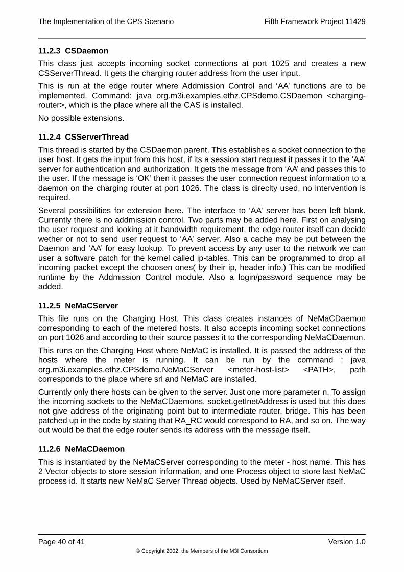
The Implementation of the CPS Scenario Fifth Framework Project 11429
© Copyright 2002, the Members of the M3I Consortium
Page 40 of 41 Version 1.0
11.2.3 CSDaemon
This class just accepts incoming socket connections at port 1025 and creates a newCSServerThread. It gets the charging router address from the user input.
This is run at the edge router where Addmission Control and ‘AA’ functions are to beimplemented. Command: java org.m3i.examples.ethz.CPSdemo.CSDaemon <charging-router>, which is the place where all the CAS is installed.
No possible extensions.
11.2.4 CSServerThread
This thread is started by the CSDaemon parent. This establishes a socket connection to theuser host. It gets the input from this host, if its a session start request it passes it to the ‘AA’server for authentication and authorization. It gets the message from ‘AA’ and passes this tothe user. If the message is ‘OK’ then it passes the user connection request information to adaemon on the charging router at port 1026. The class is direclty used, no intervention isrequired.
Several possibilities for extension here. The interface to ‘AA’ server has been left blank.Currently there is no addmission control. Two parts may be added here. First on analysingthe user request and looking at it bandwidth requirement, the edge router itself can decidewether or not to send user request to ‘AA’ server. Also a cache may be put between theDaemon and ‘AA’ for easy lookup. To prevent access by any user to the network we canuser a software patch for the kernel called ip-tables. This can be programmed to drop allincoming packet except the choosen ones( by their ip, header info.) This can be modifiedruntime by the Addmission Control module. Also a login/password sequence may beadded.
11.2.5 NeMaCServer
This file runs on the Charging Host. This class creates instances of NeMaCDaemoncorresponding to each of the metered hosts. It also accepts incoming socket connectionson port 1026 and according to their source passes it to the corresponding NeMaCDaemon.
This runs on the Charging Host where NeMaC is installed. It is passed the address of thehosts where the meter is running. It can be run by the command : javaorg.m3i.examples.ethz.CPSdemo.NeMaCServer <meter-host-list> <PATH>, pathcorresponds to the place where srl and NeMaC are installed.
Currently only there hosts can be given to the server. Just one more parameter n. To assignthe incoming sockets to the NeMaCDaemons, socket.getInetAddress is used but this doesnot give address of the originating point but to intermediate router, bridge. This has beenpatched up in the code by stating that RA_RC would correspond to RA, and so on. The wayout would be that the edge router sends its address with the message itself.
11.2.6 NeMaCDaemon
This is instantiated by the NeMaCServer corresponding to the meter - host name. This has2 Vector objects to store session information, and one Process object to store last NeMaCprocess id. It starts new NeMaC Server Thread objects. Used by NeMaCServer itself.

Fifth Framework Project 11429 The Implementation of the CPS Scenario
© Copyright 2002, the Members of the M3I Consortium
Version 1.0 Page 41 of 41
11.2.7 NeMaCServerThread
This class connects to the incoming socket provided by its parent class. It extracts from itthe various parameters send in the user request like contract id, user id, source anddestination address etc. It stores this information in the parent Vector cmrs. It alsogenerates a string of the form shown below, and puts it into a Vector sessions :SourcePeerAddress == "+sourceIP+" && SourceTransAddress == "+sourcePort+" &&DestPeerAddress == "+destIP+" && DestTransAddress == "+destPort+". This is used tocreate a rule file. Next part is writing a srl file. A srl file is created with the file name <meter-host>.testbed.srl. The fouth line is the SETstatement, describing the rule set number. Nextis the FORMAT statement, which tells NeTraMet what details to write down in the flow filesproduced. After that we have a statement : if SourcePeerType == IP save; else ignore; hereif the packets received by NeTraMet are IP then they are copied else ignored. Nextstatement says that if the packets are of tcp or udp type only the save them. Next statementis the main filter to identify flows by their 4 address parameters which are known. Onlythese packets are counted. The filter statement is generated using the Vector sessions,which was described above. If there is more than one session then an or symbol (||) is putbetween two such statements. The file creation process is done whenever the Vectorsessions is updated by new session or delete session. Next this file is compiled to a rule filewith the name <meter-host>.testbed.rules. The thread waits till the file is compiled. NowNeMaC(meter manager) is started. The parametes passed to the NeMaC are : -c<sampling-time> the rate at which NeMaC should query the meter for new data. -r <rule-filename> name of the rule file ie. meter-host.testbed.rules. The meter-host name, the snmpcommunity name and the owner of this meter. This process is started and its processID isstored in the parent variable process, and the earlier process is now terminated. A <meter-host>.session file is also written to communicate with the CAS connector the ongoingsessions. No user intervention required.
There is no need for format statement as the flow files produced by NeMaC are not used. Ifpossible there may be some other way to communicate with the connector the ongoingsessions, may be using RMI objects. Earlier different instances of NeMaC were used foreach session, but this was inefficient and also due to the SET field there was a limitation ofonly 10 possible rule files to be uploaded.


![Muriel Figueredo Franco Bruno Rodrigues Burkhard Stiller · protection services, but also offer alternatives regarding the deployment and management aspects of such services [6] [9].](https://static.fdocuments.us/doc/165x107/5f050e627e708231d4110a4b/muriel-figueredo-franco-bruno-rodrigues-burkhard-stiller-protection-services-but.jpg)