#11 Stop and See: Mind Hacking, Meditation and Leadership - with Vincent Horn

ISSUE DATE : May. 10, 2006
www.andamiro.comwww.andamirousa.com
ONLY
STOPPlease read the manual carefully and keep it in mind before usingthis machine.
Put this manual within touch of your reference in anytime.
www.andamirousa.com

www.andamiro.com
3
Contents
1. SPECIFICATION AND DIMENSION1-1. DIMENSION 1-2. SPECIFICATION
2. NAME OF PARTS & STICKER LOCATION2-1. NAME OF PARTS2-2. STICKER LOCATION
3. COMPONENTS
4. HOW TO ASSEMBLE
5. SETUP MODE AND ERROR NO5-1. FLOW CHART5-2. GAME MODE5-3. ERROR
6. TEST MODE6-1. TEST MODE CONTENTS6-2. SENSOR & SWITCH TEST6-3. SOUND TEST
7. TROUBLESHOOTING7-1. ERROR #17-2. ERROR #27-3. ERROR #37-4. ERROR #47-5. WHEN TICKETS ARE DISPENSED
8. ASSEMBLING8-1. ASSEMBLING BILLBOARD8-2. ASSEMBLING FND8-3. ASSEMBLING TOP DOOR8-4. ASSEMBLING ELEVATOR8-5. ASSEMBLING GAME PANEL
8-5-1. ASSEMBLING GAME PANEL8-5-2. ASSEMBLING GAME PANEL8-5-3. ASSEMBLING GAME PANEL8-5-4. ASSEMBLING GAME PANEL
8-6. ASSEMBLING LOWER CABINET8-6-1. ASSEMBLING LOWER CABINET8-6-2. ASSEMBLING LOWER CABINET
8-7. ASSEMBLING UPPER CABINET8-7-1. ASSEMBLING UPPER CABINET8-7-2. ASSEMBLING UPPER CABINET
8-8. ASSEMBLING FRONT & SIDE MOLDING
9. WIRING DIAGRAM
10. MEMO

www.andamiro.com
4
PRECAUTIONS FOR USEPRECAUTIONS FOR USE
5
PRECAUTIONS FOR USE PRECAUTIONS FOR USE
For safty reasons.• The following suggestions should be adhered to:
• The following graphic suggestions describe the types of precautions to be followed.
• Precautions to be followed:
C A U T I O NDisregarding could result in injury or product damage.
W A R N I N GDisregarding could result in serious injury.
Indicates a matter which must be performed.
Indicates a care should be taken.
Certain procedures require a qualified in-shop maintenance person or industry specialist. For suchinstructions, a qualified person must take care of the jobs.
Otherwise an electric shock, machine trouble, or a serious accident may result.Replacing the machine parts, inspecting and maintaining the machines, and troubleshooting must be assigned onlyto a qualified in-shop maintenance person or industry specialist. This booklet gives instructions that hazardous jobs inparticular must be handled by an industry specialist. Qualified in-shop maintenance person and industry specialist aredefined as follows.
Qualified in-shop maintenance personA service staff shall have experience in operations of game machines. The staff shall be responsible for assembly,installation, inspection and maintenance of the machine.
Industry specialistAn industry specialist must be engaged in designing, manufacturing, inspecting and servicing amusement machines.He or she must have an education in electrical, electronic and mechanical engineering, and routinely maintain andrepair amusement machines.
Forbidden.
The following safety precautions are given throughout this manual. They must be strictly followed to protect those who install,use or maintain this product as well as to protect players, visitors and property.
Be sure to consult an industry specialist whensetting up, moving or transporting this product.
This product should not be set up, moved or transportedby any one other than an industry specialist. When installing this product, set the 4 leg levelers evenlyon the floor and make sure that the product is installedstably in a horizontal position. Unstable installation mayresult in injury or accident.When installing this product, do not apply undue force onmovable parts. Otherwise, injury and accident may result,or the product may be damaged.
The machine for indoor usage only does notinstall outside.
Do not set the game machine up nearemergency exits.
Protect the game machine from:Rain or moisture.Direct sunlight.Direct heat from air-conditioning and heating equipment,etc..Hazardous flammable substances.Otherwise an accident or malfunction may result.
Do not place containers holding chemicals orwater on or near the game machine.
Do not place objects near the ventilatingholes.
Do not bend the power cord by force or placeheavy objects on it.
Never plug or unplug the power cord with wethands.
Never unplug the game machine by pullingthe power cord.
Be sure to use indoor wiring within the specifiedvoltage requirements. For extension cord, use thespecified rating or more.
Be sure to use the attached power cord.
Never plug more than one cord at a time intothe electrical receptacle.
Do not lay the power cord where peoplewalk through.
Be sure to ground this product.
Do not exert excessive force when movingthe machine.
For proper ventilation, keep the game machine100mm(4 ) away from the walls.
Do not alter the system related dipswitch settings.
W A R N I N G C A U T I O N
www.andamiro.com
6 7
PRECAUTIONS FOR USE PRECAUTIONS FOR USE
C A U T I O NW A R N I N G
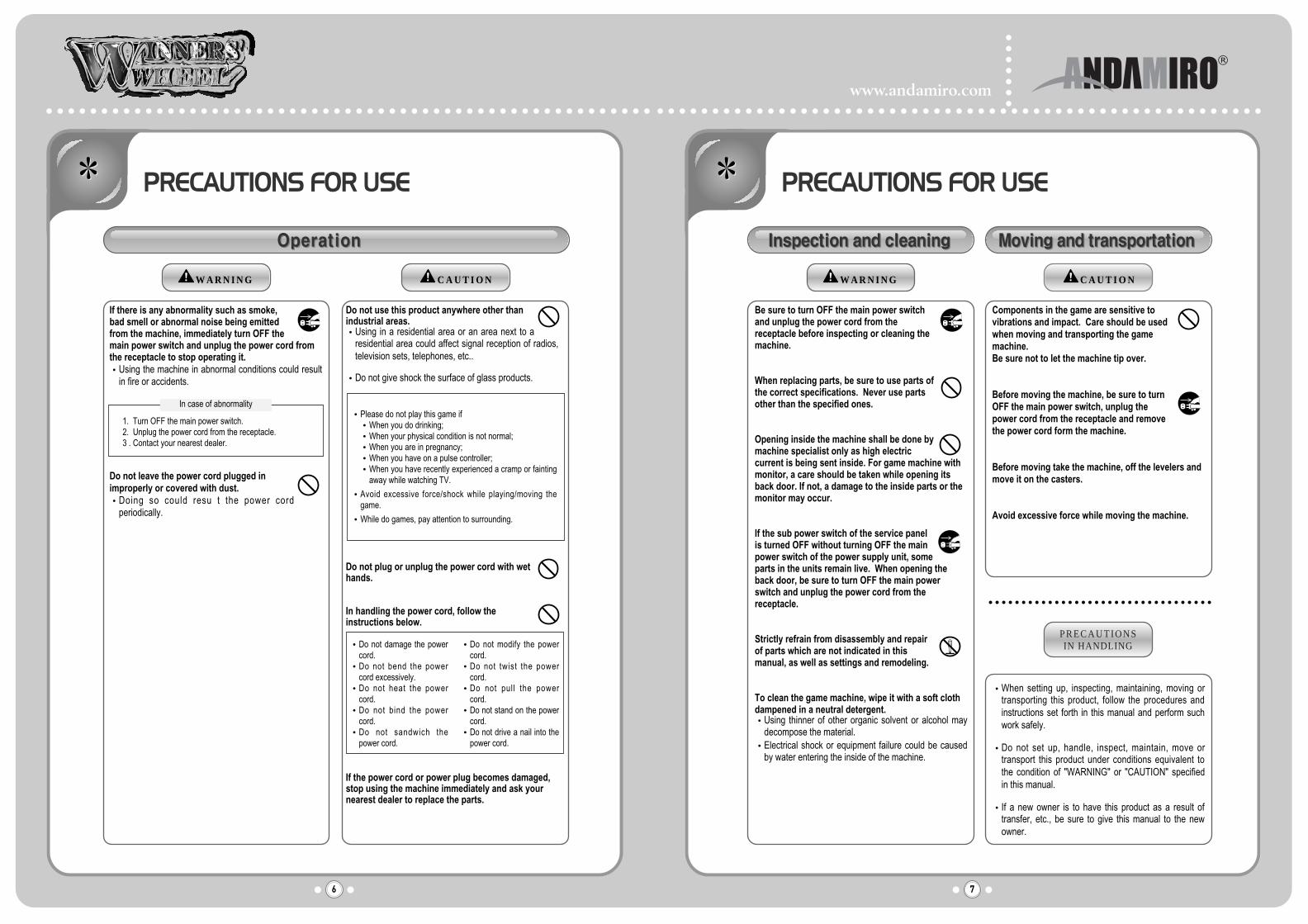
Components in the game are sensitive tovibrations and impact. Care should be usedwhen moving and transporting the gamemachine.Be sure not to let the machine tip over.
Before moving the machine, be sure to turnOFF the main power switch, unplug thepower cord from the receptacle and removethe power cord form the machine.
Before moving take the machine, off the levelers andmove it on the casters.
Avoid excessive force while moving the machine.
P R E C A U T I O N SIN HANDLING
When setting up, inspecting, maintaining, moving ortransporting this product, follow the procedures andinstructions set forth in this manual and perform suchwork safely.
Do not set up, handle, inspect, maintain, move ortransport this product under conditions equivalent tothe condition of "WARNING" or "CAUTION" specifiedin this manual.
If a new owner is to have this product as a result oftransfer, etc., be sure to give this manual to the newowner.
Be sure to turn OFF the main power switchand unplug the power cord from thereceptacle before inspecting or cleaning themachine.
When replacing parts, be sure to use parts ofthe correct specifications. Never use partsother than the specified ones.
Opening inside the machine shall be done bymachine specialist only as high electriccurrent is being sent inside. For game machine withmonitor, a care should be taken while opening itsback door. If not, a damage to the inside parts or themonitor may occur.
If the sub power switch of the service panelis turned OFF without turning OFF the mainpower switch of the power supply unit, someparts in the units remain live. When opening theback door, be sure to turn OFF the main powerswitch and unplug the power cord from thereceptacle.
Strictly refrain from disassembly and repairof parts which are not indicated in thismanual, as well as settings and remodeling.
To clean the game machine, wipe it with a soft clothdampened in a neutral detergent.
Using thinner of other organic solvent or alcohol maydecompose the material.Electrical shock or equipment failure could be causedby water entering the inside of the machine.
If there is any abnormality such as smoke,bad smell or abnormal noise being emittedfrom the machine, immediately turn OFF themain power switch and unplug the power cord fromthe receptacle to stop operating it.
Using the machine in abnormal conditions could resultin fire or accidents.
Do not leave the power cord plugged inimproperly or covered with dust.
Doing so could resu t the power cordperiodically.
C A U T I O NW A R N I N G
Do not use this product anywhere other thanindustrial areas.
Using in a residential area or an area next to aresidential area could affect signal reception of radios,television sets, telephones, etc..
Do not give shock the surface of glass products.
Do not plug or unplug the power cord with wethands.
In handling the power cord, follow theinstructions below.
If the power cord or power plug becomes damaged,stop using the machine immediately and ask yournearest dealer to replace the parts.
1. Turn OFF the main power switch.2. Unplug the power cord from the receptacle.3 . Contact your nearest dealer.
In case of abnormalityPlease do not play this game if
When you do drinking;When your physical condition is not normal;When you are in pregnancy;When you have on a pulse controller;When you have recently experienced a cramp or faintingaway while watching TV.
Avoid excessive force/shock while playing/moving thegame.
While do games, pay attention to surrounding.
Do not damage the powercord.Do not bend the powercord excessively.Do not heat the powercord.Do not bind the powercord.Do not sandwich thepower cord.
Do not modify the powercord.Do not twist the powercord.Do not pull the powercord.Do not stand on the powercord.Do not drive a nail into thepower cord.

www.andamiro.com
8 9
SPECIFICATION AND DIMENSION NAME OF PARTS & STICKER LOCATION
POWER RATED VOLTAGE RANGE
POWER RATED FREQUENCY RANGE
CONSUMPTION
WEIGHT
SEE THE FRONT PAGE
50Hz ~60Hz
200W
168kg
1-1. DIMENSION 2-1. NAME OF PARTS
2-2. STICKER LOCATION1-2. SPECIFICATION

10
COMPONENTS
www.andamiro.com
11
HOW TO ASSEMBLE
NO. PART NAME SPEC. QUANTITY CODE NO.
1
2
3
4
5
6
7
8
9
10
11
12
13
14
WRENCH
AC POWER CORD
FRONT DOOR KEY
TOP DOOR KEY
BALL
BOLT
BOLT
MANUAL
TRY AGAIN SHEET
NUMBER 3 SHEET
NUMBER 5 SHEET
NUMBER 10 SHEET
NUMBER 15 SHEET
NUMBER 50 SHEET
3mm
7001
43
M6 20L
M4 10L
MANUAL
1
1
1
2
7
5
5
1
1
2
2
1
1
1
-
-
-
-
-
-
-
-
-
-
-
-
-
-

www.andamiro.com
13
SETUP MODE AND ERROR NO
12
SETUP MODE AND ERROR NO
5-1. FLOW CHART 5-2. GAME MODE
Push SW1 button to get into Setting ModePush SW2 button to move to next modePush SW3 button to select a modeTo change the value of the right FND after selecting a mode take following steps.1) Push SW2 button move to next digit of FND2) Push SW3 button to change the number of flickering number3) Push SW1 button to be back to the first setting mode after setting the FND value
H-5H-6
H-7
H-8
H-1
H-2
H-3
H-4
Initial ticket numbers for Bonus ( 0 ~ 250 )
Maximum ticket numbers for Bonus ( 0 ~ 999 )
Mercy ticket numbers ( 0 ~ 250 )
Progressive ticket numbers per one credit ( 0 ~ 250 )
Wheel speed ( 0 ~ 9)
Ticket numbers for hole #1 ( 0 ~ 250 )
Ticket numbers for hole #2 ( 0 ~ 250 )
Ticket numbers for hole #3 ( 0 ~ 250 )
Ticket numbers for hole #4 ( 0 ~ 250 )
Ticket numbers for hole #5 ( 0 ~ 250 )
Ticket numbers for hole #6 ( 0 ~ 250 )
Ticket numbers for hole #7 ( 0 ~ 250 )
Ticket numbers for hole #8 ( 0 ~ 250 )
Demo Sound ON/OFF ("1"->ON, "0"->OFF)
Wheel Hole Number
Setup Mode
www.andamiro.com
15
TEST MODE
146
8
10
212
14
SETUP MODE AND ERROR NO
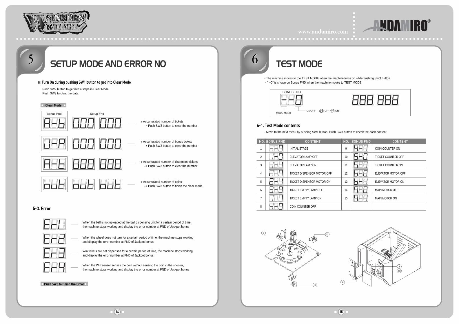
Turn On during pushing SW1 button to get into Clear Mode
5-3. Error
Push SW2 button to get into 4 steps in Clear Mode Push SW3 to clear the data
6-1. Test Mode contents- Move to the next menu by pushing SW1 button. Push SW3 button to check the each content.
- The machine moves to the TEST MODE when the machine turns on while pushing SW3 button- " --0" is shown on Bonus FND when the machine moves to TEST MODE
Accumulated number of tickets--> Push SW3 button to clear the number
Accumulated number of bonus tickets--> Push SW3 button to clear the number
Accumulated number of dispensed tickets--> Push SW3 button to clear the number
Accumulated number of coins --> Push SW3 button to finish the clear mode
When the ball is not uploaded at the ball dispensing unit for a certain period of time, the machine stops working and display the error number at FND of Jackpot bonus
When the wheel does not turn for a certain period of time, the machine stops workingand display the error number at FND of Jackpot bonus
Win tickets are not dispensed for a certain period of time, the machine stops workingand display the error number at FND of Jackpot bonus
When the Win sensor senses the coin without sensing the coin in the shooter,the machine stops working and display the error number at FND of Jackpot bonus
Clear Mode
Push SW3 to finish the Error
NO. BONUS FND CONTENT NO. BONUS FND CONTENT
1
2
3
4
5
6
7
8
INITIAL STAGE
ELEVATOR LAMP OFF
ELEVATOR LAMP ON
TICKET DISPENSOR MOTOR OFF
TICKET DISPENSOR MOTOR ON
TICKET EMPTY LAMP OFF
TICKET EMPTY LAMP ON
COIN COUNTER OFF
COIN COUNTER ON
TICKET COUNTER OFF
TICKET COUNTER ON
ELEVATOR MOTOR OFF
ELEVATOR MOTOR ON
MAIN MOTOR OFF
MAIN MOTOR ON
9
10
11
12
13
14
15

www.andamiro.com
17
TROUBLESHOOTING
16
TEST MODE
6-2. Sensor & Switch test- When a sensor or switch is checked, following numbers are shown on FND.
7-1. Error #01- Test "Elevator Motor On" in Test Mode 6-1 and see if the motor does not work.
6-3. Sound test- Check the sounds by pushing SW2. Every pushing SW2 can make next sound.
NO. CONTENT SETUP
SENSOR CHECK OF TICKET DISPENSOR
SENSOR CHECK FOR TICKET EMPTY
SWITCH CHECK OF BALL ELEVATOR SYSTEM
UPPER SENSOR CHECK OF SENSOR PCB
LOWER SENSOR CHECK OF SENSOR PCB
SWITCH CHECK FOR A DISPENSED BALL
SWITCH CHECK FOR COIN FELL INTO THEWIN HOLE
There are two switches for samefunction
COIN CHECK FOR A COIN INSERTED INTOCOIN SELECTOR
1
2
3
4
5
6
7
8

www.andamiro.com
19
TROUBLESHOOTING
18
TROUBLESHOOTING
7-2. Error # 02- Test "Main Motor ON" in the Test Mode 6-1 and see if the motor works.
7-3. Error #03- Check if the tickets are empty.

www.andamiro.com
21
TROUBLESHOOTING
20
TROUBLESHOOTING
7-4. Error #4- Check micro switch to check coin according to #7 & 8 of Test Mode 6-2.
7-5. When tickets are not dispensed after coin correctly falls into the WIN hole- Check if the number of Error is "03" on Bonus FND.- Check a micro switch to check a ball dropped into ball-out hole according to #6 of the Test Mode 6-2.

www.andamiro.com
23
ASSEMBLING
22
ASSEMBLING
8-1. ASSEMBLING BILLBOARD 8-2. ASSEMBLING FND
NO. PART NAME SPEC. QUANTITY CODE NO.
1
2
3
4
5
BILLBOARD FIXING FRAME ASS'Y
BILLBIARD ACRYL
BILLBOARD
BILLBOARD LED PCB ASS'Y - L
BILLBOARD LED PCB ASS'Y - R
-
-
-
-
-
2
1
1
1
1
MWIW0MEP019
MWIW0ACR011
MWIW0ACR015
AWIW0PCB011
AWIW0PCB012
NO. PART NAME SPEC. QUANTITY CODE NO.
1
2
3
4
5
FND BRACKET ASS'Y
FND BRACKET COVER
FND BRACKET PIPE HOUSING
FND ACRYL
FND PCB ASS'Y
-
-
-
-
-
1
1
2
1
-
MWIW0MEP018
MWIW0MEP045
MWIW0PRO035
MWIW0ACR014
MWIW0PCB010

www.andamiro.com
25
ASSEMBLING
24
ASSEMBLING
8-3. ASSEMBLING TOP DOOR 8-4. ASSEMBLING ELEVATOR
NO. PART NAME SPEC. QUANTITY CODE NO.
1
2
3
4
5
6
TOP DOOR FRAME ASS'Y
TOP DOOR WINDOW BRACKET-C
TOP DOOR WINDOW BRACKET-B
TOP DOOR WINDOW BRACKET-A
TOP DOOR WINDOW BRACKET-D
TOP DOOR WINDOW
-
-
-
-
-
1
2
1
2
1
1
MWIW0MEP021
MWIW0MEP042
MWIW0MEP041
MWIW0MEP040
MWIW0MEP048
MWIW0GLA002
NO. PART NAME SPEC. QUANTITY CODE NO.
1
2
3
4
5
6
7
8
9
10
11
12
13
14
ELEVATOR BRACKET-A ASS'Y-L
ELEVATOR BRACKET-A ASS'Y-R
ELEVATOR MOTOR BRACKET
BALL LIFT BRACKET
ELEVATOR BRACKET SPACE
TENSION ROLLER STOPPER
ELEVATOR ROLLER ASS'Y
TIMMING BELT PULLEY
TIMMING BELT
ELEVATOR ROLLER-B
ROLLER BUSH HOUSING ASS'Y
CONVEYOR BELT
ELEVATOR ROLLER-A
MOTOR
-
-
-
-
-
-
-
-
120XL-9.5t
-
-
-
-
KGE-083-3448D
1
1
1
8
2
2
1
2
1
1
4
1
1
1
MWIW0MEP016
MWIW0MEP016
MWIW0MEP036
MWIW0MEP002
MWIW0PR032
MWIW0MEP049
MWIW0PRO027
MWIW0PR030
MWET0BEL001
MWET0BEL001
MWIW0PRO028
MWIW0BEL001
MWIW0PRO033
MMAL0MOT004
www.andamiro.com
27
ASSEMBLING
26
ASSEMBLING
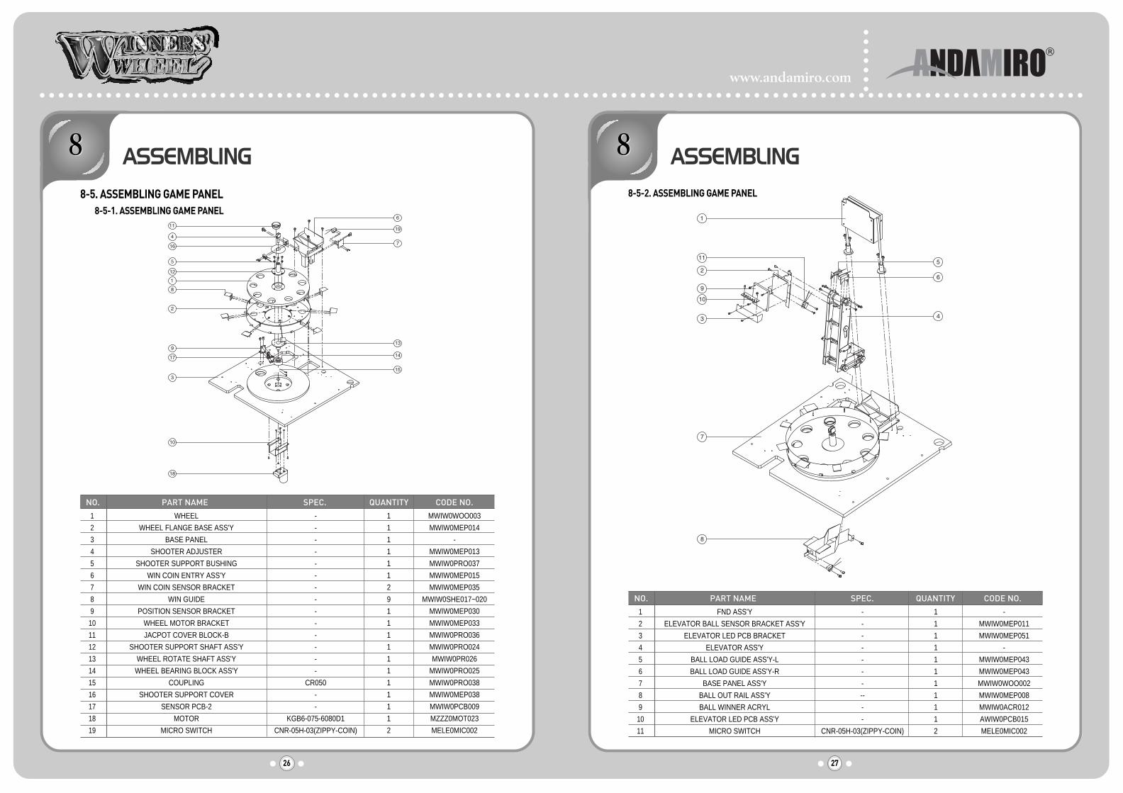
8-5. ASSEMBLING GAME PANEL8-5-1. ASSEMBLING GAME PANEL
8-5-2. ASSEMBLING GAME PANEL
NO. PART NAME SPEC. QUANTITY CODE NO.
1
2
3
4
5
6
7
8
9
10
11
12
13
14
15
16
17
18
19
WHEEL
WHEEL FLANGE BASE ASS'Y
BASE PANEL
SHOOTER ADJUSTER
SHOOTER SUPPORT BUSHING
WIN COIN ENTRY ASS'Y
WIN COIN SENSOR BRACKET
WIN GUIDE
POSITION SENSOR BRACKET
WHEEL MOTOR BRACKET
JACPOT COVER BLOCK-B
SHOOTER SUPPORT SHAFT ASS'Y
WHEEL ROTATE SHAFT ASS'Y
WHEEL BEARING BLOCK ASS'Y
COUPLING
SHOOTER SUPPORT COVER
SENSOR PCB-2
MOTOR
MICRO SWITCH
-
-
-
-
-
-
-
-
-
-
-
-
-
-
CR050
-
-
KGB6-075-6080D1
CNR-05H-03(ZIPPY-COIN)
1
1
1
1
1
1
2
9
1
1
1
1
1
1
1
1
1
1
2
MWIW0WOO003
MWIW0MEP014
-
MWIW0MEP013
MWIW0PRO037
MWIW0MEP015
MWIW0MEP035
MWIW0SHE017~020
MWIW0MEP030
MWIW0MEP033
MWIW0PRO036
MWIW0PRO024
MWIW0PR026
MWIW0PRO025
MWIW0PRO038
MWIW0MEP038
MWIW0PCB009
MZZZ0MOT023
MELE0MIC002
NO. PART NAME SPEC. QUANTITY CODE NO.
1
2
3
4
5
6
7
8
9
10
11
FND ASS'Y
ELEVATOR BALL SENSOR BRACKET ASS'Y
ELEVATOR LED PCB BRACKET
ELEVATOR ASS'Y
BALL LOAD GUIDE ASS'Y-L
BALL LOAD GUIDE ASS'Y-R
BASE PANEL ASS'Y
BALL OUT RAIL ASS'Y
BALL WINNER ACRYL
ELEVATOR LED PCB ASS'Y
MICRO SWITCH
-
-
-
-
-
-
-
--
-
-
CNR-05H-03(ZIPPY-COIN)
1
1
1
1
1
1
1
1
1
1
2
-
MWIW0MEP011
MWIW0MEP051
-
MWIW0MEP043
MWIW0MEP043
MWIW0WOO002
MWIW0MEP008
MWIW0ACR012
AWIW0PCB015
MELE0MIC002
www.andamiro.com
29
ASSEMBLING
28
ASSEMBLING
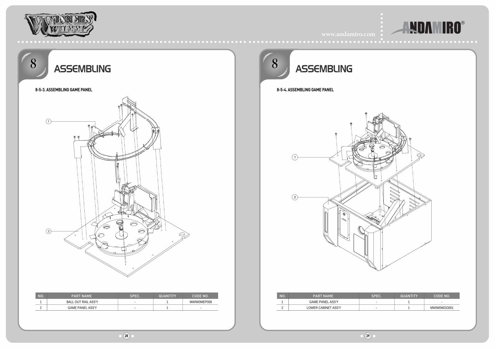
8-5-3. ASSEMBLING GAME PANEL 8-5-4. ASSEMBLING GAME PANEL
NO. PART NAME SPEC. QUANTITY CODE NO.
1
2
BALL OUT RAIL ASS'Y
GAME PANEL ASS'Y
-
-
1
1
MWIW0MEP008
-
NO. PART NAME SPEC. QUANTITY CODE NO.
1
2
GAME PANEL ASS'Y
LOWER CABINET ASS'Y
-
-
1
1
-
MWIW0WOO001

www.andamiro.com
31
ASSEMBLING
30
ASSEMBLING
8-6. ASSEMBLING LOWER CABINET8-6-1. ASSEMBLING LOWER CABINET
8-6-2. ASSEMBLING LOWER CABINET
NO. PART NAME SPEC. QUANTITY CODE NO.
1
2
3
4
5
6
7
8
9
10
11
12
13
14
15
16
17
FRONT FRAME-L
FRONT FRAME-R
FRONT LAMP BRACKET
COIN IN GUIDE ASS'Y
COIN BOX ENTRY BRACKET
LOWER CABINET
REAR PANEL
FRONT PANEL
HINGE ASSEMBLY
COIN BOX ASS'Y
FRONT LIGHT ACRYL-B
FRONT LIGHT ACRYL-B COVER
FRONT LIGHT ACRYL
ELECTRONIC BALLAST
SPEAKER
TICKET DOOR ASS'Y
MAIN BOARD
-
-
-
-
-
-
-
-
-
-
-
-
-
FL20W-DK2221-110V
MID 4.5
AMTD100A
-
1
1
2
1
1
1
1
1
2
1
2
2
2
2
1
1
1
MWIW0MEP024
MWIW0MEP024
MWIW0MEP025
MWIW0MEP010
MWIW0MEP046
MWIW0WOO001
-
-
MWIW0MEP028
MWIW0MEP009
MWIW0ACR013
MWIW0MEP050
MWIWOACR009
MELEOBAL001
MZZZ0SPE004
AHAMOPRE001
AWIW0PCB013
NO. PART NAME SPEC. QUANTITY CODE NO.
POWER SMPS
AC JOIN PCB ASS'Y BRACKET
AC JOIN PCB ASS'Y
-
-
100-250V,12V7V,5V8V MELE0SMP017
MMUN0PRO008
AMUM0PCB010
1
1
1
1
2
3
NO. PART NAME SPEC. QUANTITY CODE NO.
AC INPUT BRACKET
NOISE FILTER
-
IP-0642-H2
MWIW0MEP023
MELE0NOI002
1
1
1
2
NO. PART NAME SPEC. QUANTITY CODE NO.
AC POWER SWITCH BRACKET
COUNTER
VOLUME KNOB
PUSH BUTTON SWITCH-W
PUSH BUTTON SWITCH-R
ROCKER SWITCH
VOLUME
SETTING FND PCB
-
AMMC-712(7D12V)
-
412W
412 R
T-125 4P
BA25Y-10KΩ
-
MWIW0MEP039
MZZZ0COU002
MELE0VOL006
MELE0PUS002
MELE0PUS001
MELE0SWI004
MELE0VOL008
AWIW0PCB008
1
2
1
2
1
1
1
1
1
2
3
4
5
6
7
8
NO. PART NAME SPEC. QUANTITY CODE NO.
AC RECEPTACLE
3 WAVE LAMP 110V 20W
SOCKET FOR 3 WAVE LAMP MELE0ARE002
MELE0LAM005
1
1
1
2
www.andamiro.com
33
ASSEMBLING
32
ASSEMBLING
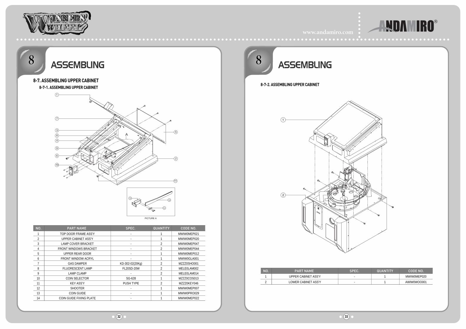
A
NO. PART NAME SPEC. QUANTITY CODE NO.
1
2
3
4
5
6
7
8
9
10
11
12
13
14
TOP DOOR FRAME ASS'Y
UPPER CABINET ASS'Y
LAMP COVER BRACKET
FRONT WINDOWS BRACKET
UPPER REAR DOOR
FRONT WINDOW ACRYL
GAS DAMPER
FLUORESCENT LAMP
LAMP CLAMP
COIN SELECTOR
KEY ASS'Y
SHOOTER
COIN GUIDE
COIN GUIDE FIXING PLATE
-
-
-
-
-
-
KD-302-02(20Kg)
FL20SD-20W
-
SG-628
PUSH TYPE
-
-
-
1
1
2
2
1
1
2
2
2
1
2
1
1
1
MWIW0MEP021
MWIW0MEP020
MWIW0MEP047
MWIW0MEP044
MWIW0MEP012
MWIW0GLA001
MZZZ0SHO001
MELE0LAM002
MELE0LAM014
MZZZ0COS013
MZZZ0KEY046
MWIW0MEP007
MWIW0PRO029
MWIW0MEP022
8-7. ASSEMBLING UPPER CABINET8-7-1. ASSEMBLING UPPER CABINET
8-7-2. ASSEMBLING UPPER CABINET
NO. PART NAME SPEC. QUANTITY CODE NO.
1
2
UPPER CABINET ASS'Y
LOWER CABINET ASS'Y
-
-
1
1
MWIW0MEP020
AWIW0WOO001

www.andamiro.com
35
WIRING DIAGRAM
34
ASSEMBLING
8-8. ASSEMBLING FRONT & SIDE MOLDING
NO. PART NAME SPEC. QUANTITY CODE NO.
1
2
3
4
5
FRONT MOLDING
FRONT MOLDING BRACKET
CABINET ASS'Y
SIDE MOLDING
SIDE MOLDING BRACKET
-
-
-
-
-
1
1
1
2
2
MWIW0ACR016
MWIW0MEP026
-
MWIW0ACR017
MWIW0MEP027

www.andamiro.com
37
MEMO
36
MEMO

38
MEMO