Cultural Dimensions of USA VOLKAN AYDıN AYKUT ÖZTÜRK VELIT TAPÇıK.

DATE for SRS Getting Started Manual
v1.0
Notice: PRE-RELEASE for comments
Volkan Gezer
26 July 2011

P a g e | 1
DATE for SRS Volkan Gezer – [email protected]
Contents Overview................................................................................................................... 2
Getting computer ready .............................................................................................. 2
Using Terminal to Configure ...................................................................................... 3
Configuring Computer for Multiple Cards .................................................................. 4
Using Network Dialog to Configure............................................................................. 5
DATE Configuration ................................................................................................. 6
DATE ...................................................................................................................... 10
Start Data Taking .................................................................................................. 10
Stop Data Taking ................................................................................................... 13
Using Data ........................................................................................................... 14
Common Errors ........................................................................................................ 15
Appendix – Text Files ................................................................................................ 17

P a g e | 2
DATE for SRS Volkan Gezer – [email protected]
Overview
The slow-control of the SRS system is carried out using UDP over IP protocol on the
available Gigabit Ethernet port of the FEC cards. When using a SRU unit to bundle many FEC
cards together, the SRU will act as a packet switch, forwarding the slow-control frames to
the FEC cards via the DTC links.
The components of the slow-control system are: the slow-control PC (SC-PC), the
network (point-to-point connection/network switch/SRU), the FEC card and the peripherals
that need to be configured. Peripherals can be either virtual devices (usually residing in the
FEC firmware) or real hardware objects which are connected to the FEC FPGA, located on
the FEC card, the A/B/C-Module Card or on the front-end hybrids. Generally the real
peripherals have a logic interface located in the FEC firmware, which translates the slow-
control commands in the format that the external device understands. The slow control
protocol assures that, from the user point of view, the real or virtual attribute of a
peripheral is transparent.
Getting computer ready After connection with SRS system using SPF (see below), it is needed to configure
computer to establish connection using UDP.
You can configure network cards of a Linux computer:
SC IP/UDP Request
SC IP/UDP Reply/Error
Data forwarded to peripherals

P a g e | 3
DATE for SRS Volkan Gezer – [email protected]
1. Using terminal
2. Using System -> Administrator -> Network dialog.
In the second option, you should always save the changes before apply. To apply for
changes, you need to Deactivate and Activate the card again. First option saves and applies
the changes automatically as you execute the commands. Below, you find the former
method on the left and the latter method on the right.
The changes on Ethernet require super user privileges. To enable super user type: su on
the terminal. You will be asked to enter the password for user.
Using Terminal to Configure
Enter super user mode and type /sbin/ifconfig to see available devices. Note the card
name you would like to use for connection. If the “UP” text inside brown box is not written
on the device details, you will need to activate device by typing: /sbin/ifconfig
ethernet_device_name up.
It is needed to assign an IP at the same subnet such as 10.0.0.3 to establish a
connection. To assign an IP type /sbin/ifconfig ethernet_device_name
IP_address_to_be_used. For the picture above, the command should be: /sbin/ifconfig eth2
10.0.0.3.
To check if your changes are applied, you can type: sbin/ifconfig
ethernet_device_name anytime. Please see image below:

P a g e | 4
DATE for SRS Volkan Gezer – [email protected]
Configuring Computer for Multiple Cards
If you have more than one card, to connect your computer with multiple cards using
one Ethernet and switch, plug the RJ45 connectors of all cards and computer in switch.
The cards need different IP addresses to send data at the same time. To enable this,
it is needed to create aliases for each card. To create aliases, enter super user mode and
type the following: /sbin/ifconfig ethernet_device_name:X IP_address_for_new_alias
netmask 255.255.255.0.
The :X part is where you create alias for your Ethernet. For instance, typing
/sbin/ifconfig eth2:0 10.0.1.3 netmask 255.255.255.0 lets a second UDP connect the
second card (The remote card must have 10.0.1.x IP address to be used (ping 10.0.1.x to
check) and UDP setting must be checked using editDb). After command execution, type
/sbin/ifconfig to see changes. To change IP addresses of cards see “Connection,
Programming and Testing FEC and ADC Cards” manual.

P a g e | 5
DATE for SRS Volkan Gezer – [email protected]
For 3rd card on SRS we would type: /sbin/ifconfig eth2:1 10.0.2.3 netmask
255.255.255.0.
(Above, ping result for second card connectivity. Ctrl+C to stop)
The created aliases are removed at each start, if you would like to keep aliases at
each reboot type in super user mode and copy-paste the
following text to the end of the file (Do not forget to change the Ethernet name you are
using for connection):
#setting IP alias interfaces
echo "Setting IP Aliases..."
/sbin/ifconfig eth2:0 10.0.1.3 netmask 255.255.255.0
# /sbin/ifconfig eth2:1 10.0.2.3 netmask 255.255.255.0 # uncomment for third
card.
To remove aliases before restart type /sbin/ifconfig eth2:X down. Like all IP
operations, this operation also needs super user privileges.
To continue the setup with multiple cards see the Date Configuration.
Using Network Dialog to Configure
Follow System -> Administrator -> Network to open Ethernet Device dialog. Double
click on the device you would like to configure and choose “Statically set IP addresses” to
enter the IP you would like to use to establish connection. Press Ctrl+S (or File -> Save) to
save changes. Click on Deactivate and Activate again to apply for changes.
To make sure you applied for changes you can use terminal and type: sbin/ifconfig
eth2 (no SU is needed).

P a g e | 6
DATE for SRS Volkan Gezer – [email protected]
Preferably, the MTU (Maximum Transmission Unit) can be increased to allow the
packet to be sent in fewer pieces. Type sbin/ifconfig ethernet_device_name mtu
desired_number to change the MTU. For dialog, check the “Set MTU to” box and edit
textbox with the desired number. After change, save changes and restart the device.
DATE Configuration If it is the first time of using DATE or any error (in red) is shown on the log or the
data is not taken, the configuration must be checked. Typing editDb (case sensitive) on the
terminal will pop the database editor up to make changes.
Choose Equipment tab and click one of the active equipments. In the following
picture udp 1 is active and chosen.
Check if ipHost (the computer) and ipBoard (destination) IPs are correct.
Please make sure that the first two parts of IP address of PC and card are the same
(10.0) to use default configuration files without modification. You can also only change the
third part of IP address. The last part must be 3 for PC and 2 for card. Some examples:
True False
Card PC Card PC
10.0.0.2 10.0.0.3 10.0.0.2 10.0.1.2
10.0.5.2 10.0.5.3 10.0.0.3 10.0.2.3
10.0.10.2 10.0.10.3 10.1.0.2 10.1.0.3
10.0.3.2 10.0.3.3 10.0.3.3 10.0.3.2
Green: fixed. Orange: Must match with card and PC IP.
To check your Ethernet IP that is used to connect the card use:

P a g e | 7
DATE for SRS Volkan Gezer – [email protected]
The picture shows that the computer has two active network cards. The Ethernet
that is used to connect card has the IP “10.0.0.3” and is named eth2.
If you have other cards in SRS, you should enable the other UDPs according to your
number of cards to enable connection and as it told before, you have to create alias for
multiple connections. Please see the image below for second UDP settings.

P a g e | 8
DATE for SRS Volkan Gezer – [email protected]
Please note that in the image, both ipHost and ipBoard addresses are changed. To
configure one Ethernet for multiple cards please read Configuring Computer for Multiple
Cards section.
It is possible to add more equipment by using New button. Choose RorcDateUDP to
add new UDP connection equipment and click Create.
Enter an EQUIPMENT_NAME and an EqId. Change IP settings according to your card
and click Add. Your new equipment will be listed on the left panel:
The newly added equipment will not be active after creation. You should activate
before use.
Close the terminal and go to Files tab of database editor. Click on SOR.commands{}
and Edit file.

P a g e | 9
DATE for SRS Volkan Gezer – [email protected]
After edit file command the following editor will be shown.
The parameters (0 1) indicate the “first card” (0) and the “last card+1” (1) to
connect. The picture above explains that only one card is to be connected. For example,
typing 0 3 here would result in the connections to FEC cards “0 1 2.” The IPs of these cards
should be configured 10.0.0.2, 10.0.1.2 and 10.0.2.2, respectively. If the first card you
connect does not have 10.0.0.2 IP address, you should also change the first parameter
according to your card IP (e.g. “2 3” for having one card with IP 10.0.2.2).

P a g e | 10
DATE for SRS Volkan Gezer – [email protected]
If the file is changed, click Commit to save changes and enable other tabs. If you
want to undo, click Rollback to discard changes.
Type to start text
editor with start0.txt.
Check the IP address at the first line. It must match the IP address that your
destination card has.
See Appendix – Text Files for description of file.
DATE The software framework of the ALICE DAQ is called DATE (ALICE Data Acquisition
and Test Environment).
Connect the card to Ethernet port of computer and ping using terminal to check if
the card is found by computer. If the IP address of card is 10.0.0.2 (default) use:
ping 10.0.0.2
If you get any replies, the connection will be possible. If not:
Check cable
Check device is on (the lights inside SRS must be on)
Check your Ethernet is configured. See above.
Check Ethernet is active (You can activate Ethernet using System > Administrator >
Network and choosing the ethernet you would like to use then clicking Activate.)
Start Data Taking

P a g e | 11
DATE for SRS Volkan Gezer – [email protected]
If the trigger is plugged in and settings are okay, starting data taking is possible by
following 5 buttons above and later using the terminal to write:
(Note that the current directory is home/daqSRS/slow_control and slow_control has no file
extension.)
If you have multiple cards, you should start them at the same time to
prevent errors. To start all cards type: ./slow_control startAll.txt

P a g e | 12
DATE for SRS Volkan Gezer – [email protected]
After step 1, clicking Define in Disconnected
Configuration shows the following dialog that
helps select detectors:
Clicking on DETECTOR will show the available
detectors shown in the picture below:
After step 2, another window should show the current status
of LDC (Local Data Concentrator). On the left, LDC is running
(the picture is taken after step 4):
Current Trigger Rate should increase on LDC Status Display window (see below). See
using data. If you do not see any changes, make sure is trigger plugged in and see Date
Configuration.

P a g e | 13
DATE for SRS Volkan Gezer – [email protected]
Stop Data Taking
To stop data taking:
If you have one card, first, type the following:
at the same directory.
If you have multiple cards type: ./slow_control stopAll.txt
The LDC status display should show that current trigger rate is decreasing:
P a g e | 14
DATE for SRS Volkan Gezer – [email protected]
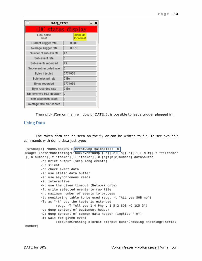
Then click Stop on main window of DATE. It is possible to leave trigger plugged in.
Using Data
The taken data can be seen on-the-fly or can be written to file. To see available
commands with dump data just type:

P a g e | 15
DATE for SRS Volkan Gezer – [email protected]
The aloneldc on the command parameter is the name of the LDC that is also shown
on the LDC Status display window.
Type to dump all events on
the terminal (Use Ctrl+C to stop). Below, find some commands to use the data:
Command Description
eventDump @aloneldc: | less Show data until screen fills. Press enter or
space to see more.
eventDump @aloneldc: -f /tmp/data -n 1000 Save first 1000th data after executing the
command into binary file named data in
folder /tmp/
eventDump /tmp/data > /tmp/data_ascii Convert data binary file into data_ascii
format to make readable.
Common Errors
The picture above shows that the destination is unreachable. It may be turned
off or configured incorrectly.
If you are having problems with getting data or the log has red entries, the DATE
might encounter error(s).

P a g e | 16
DATE for SRS Volkan Gezer – [email protected]
The easiest way to solve connection problem errors is to check the
configuration of your Ethernet and DATE configuration.
If you can contact the SRS, but cannot receive any data , the port you are
trying to connect can be blocked. Try to disable firewall by typing: /etc/init.d/iptables stop.
This will allow all ports to be reachable (You need super user privileges to disable firewall).
The firewall will be enabled automatically after rebooting the system.
You can use Wireshark to check if packets are being sent by your computer and/or
the card. To run Wireshark type wireshark on the terminal. Wireshark needs su password to
run. If you are using a switch, it is also possible to understand that data taking is started via
blinking switch leds.
The details about errors can be seen by typing infoBrowser. InfoBrowser also logs all
messages including errors. By default, it is enabled. If not, click Online to activate. Using
infoBrowser, you can also export messages and make searches for previous messages.
Making it offline enables to filter the messages by filling the fields at the bottom of the
window.
(infoBrowser Main Window)

P a g e | 17
DATE for SRS Volkan Gezer – [email protected]
If you receive “not responding error” like the picture below you should check your
network settings and UDP configuration in editDb. You should also check SOR.Commands
file to make sure that available cards in SRS are between parameter range.
(Not responding error)
If you are getting Trigger Lost error, you might not have been started the cards at
the same time. Try to stop data taking using StopAll.txt. On the main window of DATE, click
Start Processes and start the data taking again then use startAll.txt file.
If you are getting “LOCKEDBY” error, try to restart DATE again.
If you are getting “No data generating equipment” error, you do not have active
equipments. Activate using editDb and Equipments tab.
Appendix – Text Files
In this chapter, the structure of a text file will be explained briefly.
The following text file has SCS request format and used to start first card:

P a g e | 18
DATE for SRS Volkan Gezer – [email protected]
Line 1: Destination IP address
Line 2: Port number to be connected
The following lines after 2nd have 32-bit length.
The Request ID is used to match the request with reply.
SubAddress has to be written if the port requires this address. See below.
For Cmd Field 1 and 2 see the picture below:

P a g e | 19
DATE for SRS Volkan Gezer – [email protected]
For instance, to write pairs it is needed to write AAAA for 31…16 and FFFF for 15...0
(since CMD_LENGTH is not implemented).
Since CMD info is not used for write pair command, it is possible to write 00000000
(8xzeros) for Cmd field 2.
Since the write pairs command is followed by address & data pairs, you could give
registers addresses and values to change their values.
The port we are currently using in DATE is 6039.
Name Port
(hex)
Port
(dec) Use
I/F
type Description
User
level
APVAPP_PORT 1797 6039 runtime reg APV Application registers.
APV trigger sequencer and event builder user
The following table shows the register addresses after connection to 6039 port:
APV Application Registers (port 6039)
Subaddress : not used (anything)
Name Address
(hex)
Byte
count default Description
Fw.
ver.
BCLK_MODE 00 1 b00000111
(0x7)
Controls the trigger sequencer for the APV.
See table below for details
BCLK_TRGBURST 01 1 4 controls how many time slots the APV chip is

P a g e | 20
DATE for SRS Volkan Gezer – [email protected]
reading from its memory for each trigger
BCLK_FREQ 02 2 40000
(0x9C40)
Period of the trigger sequencer.
BCLK_TRGDELAY 03 2 256
(0x100)
Delay between the external/internal trigger
and the APV trigger
BCLK_TPDELAY 04 2 128
(0x80)
Delay between the external/internal trigger
and the APV test-pulse
BCLK_ROSYNC 05 2 300
(0x12C)
Delay between the external/internal trigger
and the start of data recording
EVBLD_CHMASK 08 2 0xFFFF Channel mask for the data transmission. Even
bits are masters and odd bits are slaves
EVBLD_DATALENGTH 09 2 3000
(0x0BB8)
Length of the data capture window
EVBLD_MODE 0A 1 0
Event Builder mode register.
Bit 0 = use 32-bit framecounter
Bit 1 = use 24-bit timestamp
2.05
EVBLD_EVENTINFOTYPE 0B 1 0 Controls the data format.
EVBLD_EVENTINFODATA 0C 4 0xAABB0BB8 Data for the optional info-filed in the data
format
RO_ENABLE 0F 0 Readout Enable register (bit 0). Triggers are
accepted for acquisition when this bit is 1
2.01
RST_REG FFFFFFFF Reset register.
Bit 0 = APV sync reset
2.02
The start0.txt file and descriptions as text (starting from the first line):
1. Destination IP: 10.0.0.2
2. Connection port: 6039 (decimal)
3. Request ID: 10000000000000000000000000000000 (231)
4. Subaddress: 0 (anything for this port)
5. Command: Write pairs: aa-aa-ffff (cmd-cmd type-cmd length)
6. Cmd info: 0 (not used for this command)
7. Address of register: 0F (RO_ENABLE, See table above)
8. Value of register: 1 (Triggers are accepted for acquisition)
See below for all available port connections1:
Name Port
(hex)
Port
(dec) Use
I/F
type Description
User
level
SYS_PORT 1777 6007 runtime reg System registers. Dynamic control of IP expert

P a g e | 21
DATE for SRS Volkan Gezer – [email protected]
address, MAC address, GbE parameters, ...
FEC_BI2C_PORT 1787 6023 debug
setup I2C
Access to the FEC I2C line B. Used to
program the on-board EEPROM expert
APVAPP_PORT 1797 6039 runtime reg APV Application registers.
APV trigger sequencer and event builder user
APV_PORT 1877 6263 runtime I2C Access to the I2C registers of the APV chip user
ADCCARD_PORT 1977 6519 runtime I2C I2C registers of the ADC CCARD. user
1Source: SRS Slow Control Manual