
Datavideo SE-700 4 input Digital Video Switcher
44
1
-
Upload
av-profshop -
Category
Technology
-
view
491 -
download
2
Transcript of Datavideo SE-700 4 input Digital Video Switcher

1

2
Table of Contents Warnings and Precautions ..................................................................................... 5
Warranty................................................................................................................ 5
Standard Warranty ............................................................................................. 5
Two Year Warranty ............................................................................................. 6
Disposal .............................................................................................................. 6
Packing List ......................................................................................................... 6
Introduction ........................................................................................................... 7
Features .............................................................................................................. 7
System Diagram ..................................................................................................... 8
Rear Panel .............................................................................................................. 9
Control Panel ....................................................................................................... 10
SE-700 Multi view ................................................................................................ 14
SE-700 video layers .............................................................................................. 15
Menu Options ...................................................................................................... 16
Setting the video outputs..................................................................................... 21
Setting the video input standard .......................................................................... 21
Transition effects ................................................................................................. 22
CUTTING between sources ............................................................................... 22
Mixing between sources ................................................................................... 22
Wiping between sources .................................................................................. 23
Start Menu ........................................................................................................... 24
Transition .......................................................................................................... 24
Wipe ................................................................................................................. 24
Border ............................................................................................................... 24
Position ............................................................................................................. 24
Matte ................................................................................................................ 24
Keyer.................................................................................................................... 25
3
Keyer ................................................................................................................ 25
Keyer Control .................................................................................................... 25
Key Source ........................................................................................................ 25
Fill ..................................................................................................................... 25
Chroma ............................................................................................................. 25
Mask ................................................................................................................. 26
P-In-P ................................................................................................................... 27
P-In-P Source .................................................................................................... 27
Position ............................................................................................................. 27
Border ............................................................................................................... 27
Border Width .................................................................................................... 27
Crop .................................................................................................................. 27
P-in-P Keyer ......................................................................................................... 28
P-In-P Source .................................................................................................... 28
Keyer ................................................................................................................ 28
Keyer Control .................................................................................................... 28
Chroma ............................................................................................................. 28
Mask ................................................................................................................. 29
Downstream Key .................................................................................................. 30
DSK ................................................................................................................... 30
Keyer Control .................................................................................................... 30
Key Source ........................................................................................................ 30
Fill Source ......................................................................................................... 30
Mask ................................................................................................................. 30
Still ....................................................................................................................... 31
Load Still ........................................................................................................... 31
Save Still ........................................................................................................... 31
Freeze ............................................................................................................... 31

4
User ..................................................................................................................... 32
Load Memory ................................................................................................... 32
Save Memory .................................................................................................... 32
Inputs ................................................................................................................... 32
Input 1-4 ........................................................................................................... 32
Crosspoint ......................................................................................................... 32
Outputs ................................................................................................................ 33
Outputs ............................................................................................................. 33
Audio ................................................................................................................ 33
GPI Out ............................................................................................................. 33
Setup ................................................................................................................... 34
Standard ........................................................................................................... 34
Menu Preference .............................................................................................. 34
Software ........................................................................................................... 34
GPI Connections ................................................................................................... 35
Tally Outputs........................................................................................................ 35
Firmware Upgrade ............................................................................................... 36
Frequently-Asked Questions ................................................................................ 37
Dimensions & Weight .......................................................................................... 39
Specifications ....................................................................................................... 40
Service and Support ............................................................................................. 44

5
Warnings and Precautions
1. Read all of these warnings and save them for later reference. 2. Follow all warnings and instructions marked on this unit. 3. Unplug this unit from the wall outlet before cleaning. Do not use liquid or aerosol cleaners. Use a damp
cloth for cleaning. 4. Do not use this unit in or near water. 5. Do not place this unit on an unstable cart, stand, or table. The unit may fall, causing serious damage. 6. Slots and openings on the cabinet top, back, and bottom are provided for ventilation. To ensure safe and
reliable operation of this unit, and to protect it from overheating, do not block or cover these openings. Do not place this unit on a bed, sofa, rug, or similar surface, as the ventilation openings on the bottom of the cabinet will be blocked. This unit should never be placed near or over a heat register or radiator. This unit should not be placed in a built-in installation unless proper ventilation is provided.
7. This product should only be operated from the type of power source indicated on the marking label of the AC adapter. If you are not sure of the type of power available, consult your Datavideo dealer or your local power company.
8. Do not allow anything to rest on the power cord. Do not locate this unit where the power cord will be walked on, rolled over, or otherwise stressed.
9. If an extension cord must be used with this unit, make sure that the total of the ampere ratings on the products plugged into the extension cord do not exceed the extension cord rating.
10. Make sure that the total amperes of all the units that are plugged into a single wall outlet do not exceed 15 amperes.
11. Never push objects of any kind into this unit through the cabinet ventilation slots, as they may touch dangerous voltage points or short out parts that could result in risk of fire or electric shock. Never spill liquid of any kind onto or into this unit.
12. Except as specifically explained elsewhere in this manual, do not attempt to service this product yourself. Opening or removing covers that are marked “Do Not Remove” may expose you to dangerous voltage points or other risks, and will void your warranty. Refer all service issues to qualified service personnel.
13. Unplug this product from the wall outlet and refer to qualified service personnel under the following conditions:
a. When the power cord is damaged or frayed; b. When liquid has spilled into the unit; c. When the product has been exposed to rain or water; d. When the product does not operate normally under normal operating conditions. Adjust only
those controls that are covered by the operating instructions in this manual; improper adjustment of other controls may result in damage to the unit and may often require extensive work by a qualified technician to restore the unit to normal operation;
e. When the product has been dropped or the cabinet has been damaged; f. When the product exhibits a distinct change in performance, indicating a need for service.
Warranty
Standard Warranty Datavideo equipment is guaranteed against any manufacturing defects for one year from the date of
purchase.
The original purchase invoice or other documentary evidence should be supplied at the time of any request for repair under warranty.
Damage caused by accident, misuse, unauthorized repairs, sand, grit or water is not covered by this warranty.
All mail or transportation costs including insurance are at the expense of the owner.
All other claims of any nature are not covered.
Cables & batteries are not covered under warranty.
Warranty only valid within the country or region of purchase.
Your statutory rights are not affected.

6
Two Year Warranty All Datavideo products purchased after 01-Oct.-2008 qualify for a free one year extension to the standard
Warranty, providing the product is registered with Datavideo within 30 days of purchase. For information on how to register please visit www.datavideo.com or contact your local Datavideo office or authorized Distributors
Any second year warranty claims must be made to your local Datavideo office or one of its authorized Distributors before the extended warranty expires.
Disposal
For EU Customers only - WEEE Marking
This symbol on the product indicates that it will not be treated as household waste. It
must be handed over to the applicable take back scheme for the recycling of Waste
Electrical and Electronic Equipment. For more detailed information about the recycling
of this product, please contact your local Datavideo office.
Packing List The following items should be included in the box. If any items are missing please contact your supplier.
1 x SE-700 unit 1 x Quick Start Guide 1 x Accessory List
7
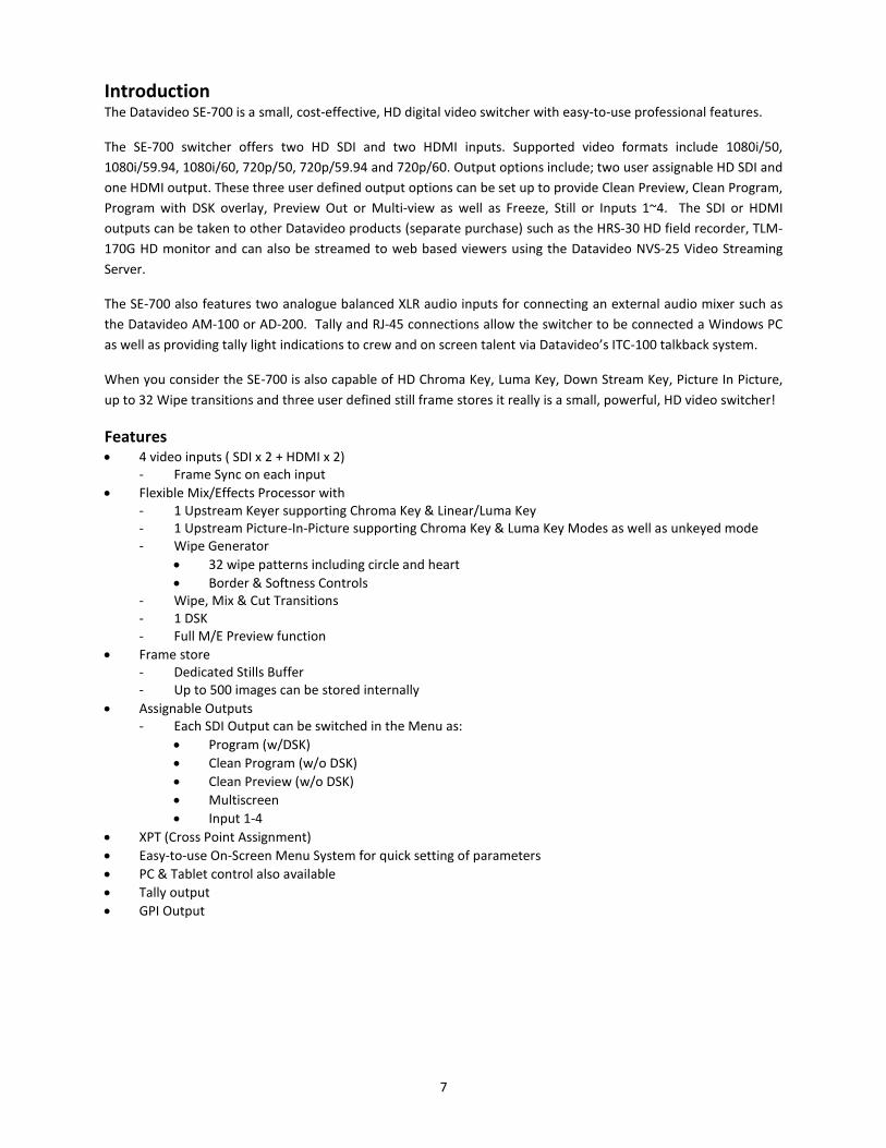
Introduction The Datavideo SE-700 is a small, cost-effective, HD digital video switcher with easy-to-use professional features.
The SE-700 switcher offers two HD SDI and two HDMI inputs. Supported video formats include 1080i/50,
1080i/59.94, 1080i/60, 720p/50, 720p/59.94 and 720p/60. Output options include; two user assignable HD SDI and
one HDMI output. These three user defined output options can be set up to provide Clean Preview, Clean Program,
Program with DSK overlay, Preview Out or Multi-view as well as Freeze, Still or Inputs 1~4. The SDI or HDMI
outputs can be taken to other Datavideo products (separate purchase) such as the HRS-30 HD field recorder, TLM-
170G HD monitor and can also be streamed to web based viewers using the Datavideo NVS-25 Video Streaming
Server.
The SE-700 also features two analogue balanced XLR audio inputs for connecting an external audio mixer such as
the Datavideo AM-100 or AD-200. Tally and RJ-45 connections allow the switcher to be connected a Windows PC
as well as providing tally light indications to crew and on screen talent via Datavideo’s ITC-100 talkback system.
When you consider the SE-700 is also capable of HD Chroma Key, Luma Key, Down Stream Key, Picture In Picture,
up to 32 Wipe transitions and three user defined still frame stores it really is a small, powerful, HD video switcher!
Features 4 video inputs ( SDI x 2 + HDMI x 2)
- Frame Sync on each input
Flexible Mix/Effects Processor with - 1 Upstream Keyer supporting Chroma Key & Linear/Luma Key - 1 Upstream Picture-In-Picture supporting Chroma Key & Luma Key Modes as well as unkeyed mode - Wipe Generator
32 wipe patterns including circle and heart
Border & Softness Controls - Wipe, Mix & Cut Transitions - 1 DSK - Full M/E Preview function
Frame store - Dedicated Stills Buffer - Up to 500 images can be stored internally
Assignable Outputs - Each SDI Output can be switched in the Menu as:
Program (w/DSK)
Clean Program (w/o DSK)
Clean Preview (w/o DSK)
Multiscreen
Input 1-4
XPT (Cross Point Assignment)
Easy-to-use On-Screen Menu System for quick setting of parameters
PC & Tablet control also available
Tally output
GPI Output
8
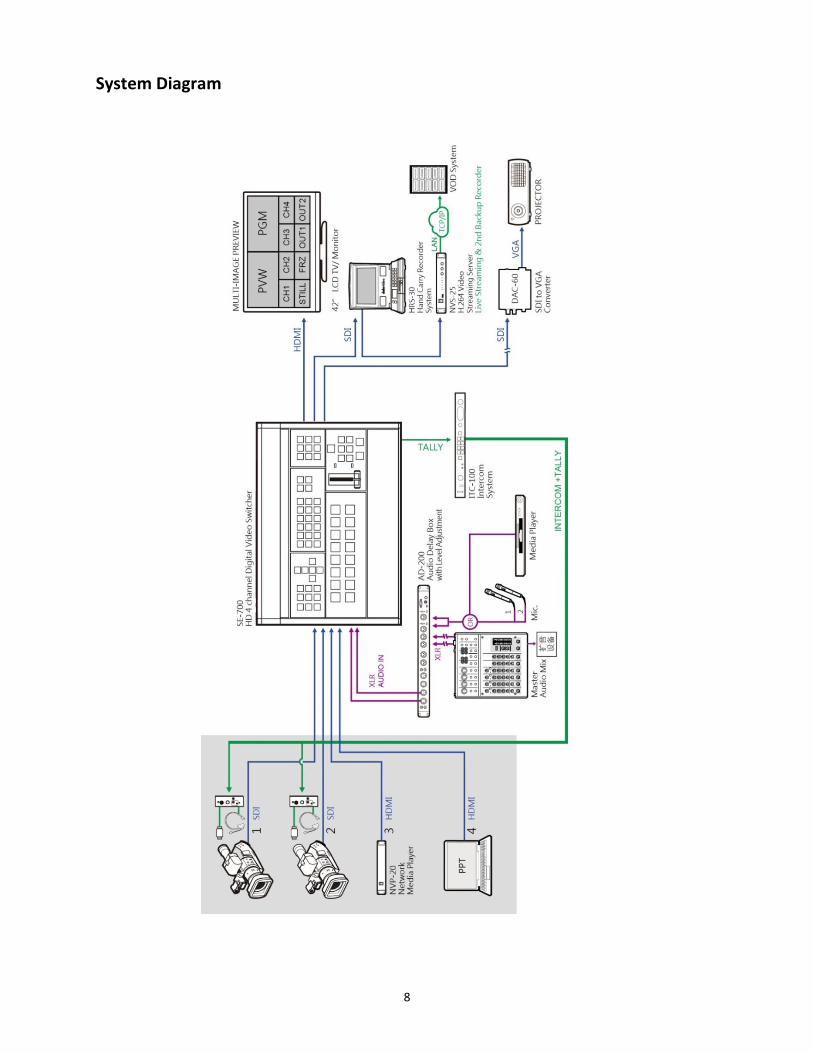
System Diagram

9
Rear Panel
Video Input Modules
The SE-700 provides four video input channels. There are two SDI inputs (BNC connectors) and two HDMI inputs.
Video Output Modules The SE-700 provides three video output channels. There are two SDI outputs (BNC connectors) and one HDMI Output.
Audio Input Two channels of XLR Balanced Audio Input.
GPI GPI output connection for basic control of other externally-connected devices
Ethernet Port This port allows IP connection of the SE-700 to a PC for Firmware Update & Control
TALLY Output Sends Red, and Green tally signals to each channel. Red indicates On-Air, and Green indicates next camera source.
DC IN DC in socket connects the supplied 12V / 19W PSU. The connection can be secured by screwing the outer fastening ring of the DC In plug to the socket.
Grounding Terminal When connecting this unit to any other component, make sure that it is properly grounded by connecting this terminal to an appropriate point. When connecting, use the socket and be sure to use wire with a cross-sectional area of at least
1.0 mm2.

10
Control Panel
1 Function Keys F1 – F3 11 DSK Selection / PGM & PVW Settings
2 User Memory 12 FTB – Fade to Black
3 Menu Control 13 Speed Selection
4 Wipe Transition Selection 14 WIPE Transition Effect
5 Wipe Border Setting 15 Take - Cut & Auto
6 Live Video Screen Capture 16 MIX Transition Effect
7 Still Frame Stores FS1, FS2, FS3 17 Transition on PVW Only
8 Background Transition Enabler 18 T-Bar for manual transitions
9 PIP Selection / PGM & PVW Settings 19 Program source row
10 Keyer Selection / PGM & PVW Settings 20 Preview source row
Function Keys F1- F3
F1: Switch USER 1-6 buttons to act as USER 7-12 buttons F2: User Mem Save Press and hold for 2 seconds All user buttons will flash (Blue LED) Press a user button to save the current setting (To turn off flashing LED without saving, press F2 again) F3: Normalise Button Mode 1 - When in Menu Select mode (left hand column of menu), pressing the 'Normalise' button will normalise all current menu items. Mode 2 - When in Sub-Menu select mode, pressing the 'Normalise' button will normalise the current menu line.
User Memory 1-6
User Memory buttons 1-6 allow the user to recall and load previously saved switcher settings. This includes PIP, Keyer and DSK settings. The switcher loads settings saved to User Memory 0 as default settings used at boot up. See the User Memory section for more information.
1 2 3 4 5 6 7 8 9 10 11 12
2
13
2
14
2
15
2
16
2
17
2
18
2
19
2
20
2

11
Menu Control
Menu Operation Press the MENU button to gain access to the menu; use the up/down/left/right arrow buttons to browse through the menu and press ENTER button to select an option or MENU button to exit.
Wipe Transition Selection
WIPE Transition Selection Each Wipe button consists of black and white colors. The white
represents the current Program image and the black represents
the WIPE-IN image. There are a total of 32 WIPE presets
offered on the SE-700; the WIPE buttons allow the user to
make a selection directly from the control panel for the first 12
and remaining 20 WIPE effects are selectable from the menu.
REV Pressing this button reverses the direction of the WIPE.
BDR ON/OFF Turns the WIPE border function ON/OFF
BDR SOFT Adjustment of the WIPE border softness To fine tune the border softness, please use the menu option “SOFT”
BDR COLOR Selection of the WIPE border color
BDR SIZE Selection of the WIPE border thickness
GRAB The GRAB feature allows the user to grab and save the current Program video image to the Freeze channel of Preset and Program rows.
FS1 – FS3 Pre-loaded still images can be assigned to the frame store buttons FS1, FS2 and FS3. Pressing an FS button loads the stored image to the STILL channel of Program and Preset rows.
TRANS BG Enables Background Transition between Program / Preset
12
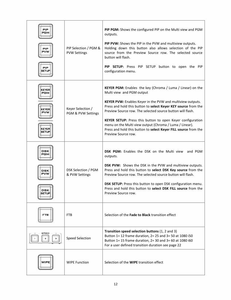
PIP Selection / PGM & PVW Settings
PIP PGM: Shows the configured PIP on the Multi view and PGM outputs. PIP PVW: Shows the PIP in the PVW and multiview outputs. Holding down this button also allows selection of the PIP source from the Preview Source row. The selected source button will flash. PIP SETUP: Press PIP SETUP button to open the PIP configuration menu.
Keyer Selection / PGM & PVW Settings
KEYER PGM: Enables the key (Chroma / Luma / Linear) on the Multi view and PGM output KEYER PVW: Enables Keyer in the PVW and multiview outputs. Press and hold this button to select Keyer KEY source from the Preview Source row. The selected source button will flash. KEYER SETUP: Press this button to open Keyer configuration menu on the Multi view output (Chroma / Luma / Linear). Press and hold this button to select Keyer FILL source from the Preview Source row.
DSK Selection / PGM & PVW Settings
DSK PGM: Enables the DSK on the Multi view and PGM outputs. DSK PVW: Shows the DSK in the PVW and multiview outputs. Press and hold this button to select DSK Key source from the Preview Source row. The selected source button will flash. DSK SETUP: Press this button to open DSK configuration menu. Press and hold this button to select DSK FILL source from the Preview Source row.
FTB Selection of the Fade to Black transition effect
Speed Selection
Transition speed selection buttons (1, 2 and 3) Button 1= 12 frame duration, 2= 25 and 3= 50 at 1080 i50 Button 1= 15 frame duration, 2= 30 and 3= 60 at 1080 i60 For a user defined transition duration see page 22
WIPE Function Selection of the WIPE transition effect

13
TAKE - Cut & Auto Cut: Immediate manual switch between selected sources Auto: Auto transition according to the speed selected
MIX Function Mix transition effect
PVW TRANS Transition shown on PVW only
BLK Black Background
STILL Select STILL picture (FS1, 2, 3 select the Still Image)
FREEZE Select FREEZE picture
BKG Background Button (Full screen color Matte or Bars)

14
SE-700 Multi view
The SE-700 Multi view output can be supplied from the HDMI or SDI outputs, see previous page. The layout of the multi view cannot be changed. The sources can be swapped around using the cross point section of the Inputs menu. The Multi view shows monitoring images for Preview (PVW), Program (PGM), Inputs 1~4, Still and Freeze channels as well as SDI outputs 1 and 2. The Multi view can also show audio level bars overlaid on the Program image. This confirms the analogue XLR audio input is being received and embedded to the selected Program output(s). A Red tally indication box is shown around the selected Program source. This video image is also seen at the switchers selected Program output(s). A Green tally indication box is shown around the selected Preview source. This will be the image source to be mixed to, wiped in or cut to next depending on the user’s preference. STILL image is an image pre-loaded from one of the SE-700’s frame stores (FS1, FS2 or FS3). See the Frame Stores section for more information. FREEZE image is a frozen image taken immediately from one of the SE-700’s four live input channels or alternatively from one of the possible 500 pre-loaded memory points. Images SDI out 1 and SDI out 2 confirm what is being sent from those SDI outputs. These outputs can be configured differently by the user, see previous page.

15
SE-700 video layers The SE-700 is a High Definition Digital Video Switcher and as well as mixing video sources and embedding analogue audio it has additional functions such as Picture in Picture (PIP), Chroma / Luma Key and Down Stream Key (DSK). Before attempting to use the SE-700’s PIP, Chroma, Luma and Down Stream Keying functions it may help to first understand the order of the video layers at the SE-700 Program outputs.
The background video layer is used for transitioning between Preview and Program sources. This layer also includes any selected wipe transitions. This layer can be hidden or hidden in part by the PiP, Keyer or DSK video layers in front of it. The Picture in Picture (PiP) layer is used for displaying a smaller secondary image in front of the background video layer. This smaller PiP image can be resized, cropped and repositioned by the user to avoid an important part of the background layer being covered by it. The Keyer layer is used for Chroma Key or Luma Key applications. The KEY video signal (foreground) is shown in this layer and the FILL video signal is displayed in the background video layer. If set up incorrectly, this layer can stop the video layers behind it being displayed properly. The Down Stream Key (DSK) layer is placed on top of all the previous layers. This layer is typically used with Character Generator inputs for displaying titles, lower thirds, clocks and logos. Datavideo offer several Character Generator Products (additional purchase) such as CG-250, CG-350 and CG-500. NB: Where possible prepare and position the upper video layers in advance of the live production starting to avoid them appearing on the program output incorrectly. Most broadcast networks have guidelines and advice on the use of video, images, music, logos and on screen text so it is best to check beforehand when planning a production. Do not use copyright protected content until you have the relevant permissions. Information on royalty free video, images and music is widely available. Please speak with your local dealer or seek professional advice.

16
Menu Options
This section covers the Menu options in the order that they appear on the screen. These settings are explained in
detail in the sub-sections. Options may vary depending on the firmware version in use.
The Main Menu will appear on the Multi view output after the MENU button is pressed. Use
UP/DOWN/LEFT/RIGHT arrows to browse through the Menu and make your selection by
pressing the ENTER button.
Please note that a long press on the up/down arrow buttons will allow the user to change
the parameter values quicker.
Main Options Sub-Options Parameters
Start
Transition
M/E Mix Effect
DSK Downstream Key Effect
FTB Fade-to-Black Effect
Wipe
Wipe Wipe Effect Presets
Soft Border Softness
Width Border Width
Border
Luma Border Color Luma
Sat Border Color Saturation
Hue Border Color Hue
Position X Horizontal Position
Y Vertical Position
Matte
Luma Background Matte Luma
Sat Background Matte Saturation
Hue Background Matte Hue
Keyer
Keyer
Linear Luma Chroma
Type of Keyer
Self Select if only one source is enabled for the keyer (Key source)
Split Select if two sources are enabled for the keyer (Fill and Key sources)
Priority Top – Set to top layer Bot – Set to bottom layer
Keyer Ctrl
Lift Parameter for dark/black areas of the overall foreground key image
Gain Parameter for light/white areas of the overall foreground key image
Opac Parameter for transparency of the overall foreground key image
Key Source
Bars Matte Freeze Still Input 4 Input 3 Input 2 Input 1 Black
Key Source Selections
Fill Fill Source Selection from Bars/Matte/Freeze/Still/Input 4/Input 3/Input 2/Input 1/Black
CK Matte
Hue Parameter for color of the chroma key
Luma Parameter for luma of the chroma key
Bg-Supp Bg-Supp turns ON/OFF background suppress
CK Key K Acc Setting the range of colors that match the background color to be keyed

17
K Lift Parameter for the Chroma key in dark or black areas
K Gain Parameter for the Chroma key in light or white areas
Hi-Light Boost the foreground key in high luminance area
Lo-Light Boost the foreground key in low luminance area
Mask
Left Left sets the left edge of the keyer mask
Right Right sets the right edge of the keyer mask
Top Top sets the top edge of the keyer mask
Bottom Bottom sets the bottom edge of the keyer mask
P-In-P
P-In-P Src
Bars Matte Freeze Still Input 4 Input 3 Input 2 Input 1 Black
P-In-P Source Selections
Position
X Horizontal PIP Position
Y Vertical PIP Position
Size PIP Size
Border
Luma PIP Border Luma
Sat PIP Border Color Saturation
Hue PIP Border Color Hue
Width PIP Border Width
Crop
Left Left Edge of the Crop
Right Right Edge of the Crop
Size Size of the Crop
Top Top Edge of the Crop
Bot Bottom Edge of the Crop
P-In-P Keyer
P-In-P Src
Bars Matte Freeze Still Input 4 Input 3 Input 2 Input 1 Black
P-In-P Source Selections
Priority Top – Set to top layer Bot – Set to bottom layer
Keyer Chroma Chromakeying on PIP screen
Full Full PIP screen
Keyer Ctrl
Lift Parameter for dark/black areas of the overall foreground key image
Gain Parameter for light/white areas of the overall foreground key image
Opac Parameter for transparency of the overall foreground key image
CK Matte
Hue Parameter for color of the Chroma key
Luma Parameter for luma of the Chroma key
Bg-Supp Bg-Supp turns ON/OFF background suppress
CK Key
K Acc Setting the range of colors that match the background color to be keyed
K Lift Parameter for the Chroma key in dark or black areas
K Gain Parameter for the Chroma key in light or white areas
Hi-Light Boost the foreground key in high luminance area
Lo-Light Boost the foreground key in low luminance area
Mask Left Left sets the left edge of the P-in-P keyer mask

18
Right Right sets the right edge of the P-in-P keyer mask
Top Top sets the top edge of the P-in-P keyer mask
Bottom Bottom sets the bottom edge of the P-in-P keyer mask
DSK
DSK
Linear Luma
Type of DSK Keyer
Self Select if only one source is enabled for DSK keyer (Key source)
Split Select if two sources are enabled for DSK keyer (Fill and Key sources)
Keyer Ctrl
Lift Parameter for dark/black areas of the overall foreground key image
Gain Parameter for light/white areas of the overall foreground key image
Opac Parameter for opacity of the overall foreground key image
Key Source
Bars Matte Freeze Still Input 4 Input 3 Input 2 Input 1 Black
Keyer Source Selections
Fill Source
Bars Matte Freeze Still Input 4 Input 3 Input 2 Input 1 Black
Keyer Source Selections
Mask
Left Left sets the left edge of the DSK keyer mask
Right Right sets the right edge of the DSK keyer mask
Top Top sets the top edge of the DSK keyer mask
Bottom Bottom sets the bottom edge of the DSK keyer mask
Still
Load Still
Still Memory Location
0-500
Load Pressing this button loads the selected still picture source
Destination
Still FS1 Still FS2 Still FS3 Input1 Input2 Input3 Input4 Freeze
Save Still
Source
Still FS1 Still FS2 Still FS3 Input1 Input2 Input3 Input4 Freeze
Save Pressing this button saves the selected still picture
Still Memory Location
0-500
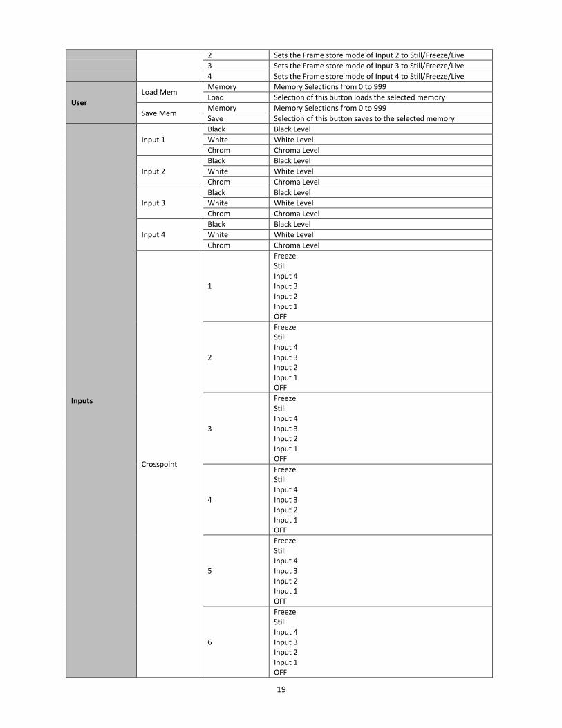
Freeze 1 Sets the Frame store mode of Input 1 to Still/Freeze/Live
19
2 Sets the Frame store mode of Input 2 to Still/Freeze/Live
3 Sets the Frame store mode of Input 3 to Still/Freeze/Live
4 Sets the Frame store mode of Input 4 to Still/Freeze/Live
User
Load Mem Memory Memory Selections from 0 to 999
Load Selection of this button loads the selected memory
Save Mem Memory Memory Selections from 0 to 999
Save Selection of this button saves to the selected memory
Inputs
Input 1
Black Black Level
White White Level
Chrom Chroma Level
Input 2
Black Black Level
White White Level
Chrom Chroma Level
Input 3
Black Black Level
White White Level
Chrom Chroma Level
Input 4
Black Black Level
White White Level
Chrom Chroma Level
Crosspoint
1
Freeze Still Input 4 Input 3 Input 2 Input 1 OFF
2
Freeze Still Input 4 Input 3 Input 2 Input 1 OFF
3
Freeze Still Input 4 Input 3 Input 2 Input 1 OFF
4
Freeze Still Input 4 Input 3 Input 2 Input 1 OFF
5
Freeze Still Input 4 Input 3 Input 2 Input 1 OFF
6
Freeze Still Input 4 Input 3 Input 2 Input 1 OFF

20
Outputs
Outputs
SDI1/SDI2/HDMI
Freeze Still Input 4 Input 3 Input 2 Input 1 CLN PVW (Clean PVW) CLN PGM (Clean PGM) PG + DSK PVW PGM MultiV (Multi view)
HDMI Output Resolution
1080i 1080p
Audio
Mode OFF/Analog
Level EBU SMPTE AUTO
SDI 1 SDI 1 Audio Enable (ON)/Disable (OFF)
SDI 2 SDI 2 Audio Enable (ON)/Disable (OFF)
HDMI HDMI Audio Enable (ON)/Disable (OFF)
GPI Out
ON/OFF GPI Enable/Disable
Mode Level/Pulse
Width Pulse width
Input 1-4 GPI-out assignment
Delay 1-99
Setup
Standard 1080i/50
Resolution Selections from 1080i/50/59.94/60 720p/60/59.94/50
Save Saves the selected resolution
Menu Pref
Blue Selection of menu color from Blue and Grey
Transp Menu transparency level of 0/1/2
Size Menu size of Normal/Small/Large
Menu Pos
Centre Top Left Right Bottom
This option sets the menu position
Software Upgrade
Selection of this button starts the FW upgrade process
(Available only when the USB storage device containing the latest firmware file is inserted)

21
Setting the video outputs
Video Output Connections The SE-700 provides three video output channels. There are two SDI outputs (BNC connectors) and one HDMI Output.
These video outputs are initially set as follows when shipped from the factory. SDI 1 Factory default – Program out with DSK SDI 2 Factory default – Program out with DSK HDMI Factory default – Multi view output (video sources as well as Preview and Program) Each of these outputs can be reconfigured to one of the settings below by using the menu path Setup > Outputs
Freeze Still Input 4 Input 3 Input 2 Input 1
Clean PVW [Preview] Clean PGM [Program] PVW out including DSK PGM out including DSK Multi view
Note: Ensure at least one output is left set as Multi View so the Main Menu can still be accessed. Note: The SE-700 HDMI multi view output only operates at the 1080P or 720P standards. This can be useful for some HDMI and DVI monitor types. If an interlaced 1080i Multi view output is needed please configure an SDI output for multi view instead.
Setting the video input standard The SE-700 is initially set up for the 1920 x 1080 i50 or i60 video standard when shipped from the factory depending on your country’s video standard. As with most HD video switchers, the SE-700 will expect all video inputs to be operating in the same video standard as the switcher itself. If a connected device is supplying a different video format/standard then the switcher may not display the video for that input. Change the source equipment settings to match the switcher’s video standard or vice versa. The SE-700 can support the following HD video standards:
1920x 1080i/50, 1080i/59.94, 1080i/60 and 1280x 720p/50, 720p/59.94, 720p/60
The switcher’s video standard can be reconfigured by using the menu path SETUP > STANDARD

22
Transition effects The SE-700 allows the user several options for cutting or transitioning between the selected preview and program
video sources.
CUTTING between sources Cutting between sources is an instant switch from the current Program video to the selected Preview source image. This can be achieved in two ways:
1. Each button press on the Program row will cause an instant clean cut to the selected source.
2. Selecting the next source on the Preset row of buttons and then pressing the CUT button.
Mixing between sources In order to mix between two video sources first ensure the Transition Background or TRANS BG button is ON.
Pressing MIX will select a mix transition to use when moving from the current video source on the Program row to the selected next source on the Preset row.
The timing of this MIX transition can be manually decided when moving the T-Bar or completed over a set time when using the AUTO button. To change the rate of transition for the AUTO button follow the menu path START> Transition and change the M/E duration value in frames. If this value is small then the transition will happen quickly. If this value is larger then the transition will take longer to complete.
TRANS BG Enables Background Transition between Program / Preset
Mix transition effect

23
Wiping between sources
In order to WIPE between two video sources first ensure the transition background or TRANS BG button is ON.
TRANS BG Enables background transition between Program / Preset
Pressing WIPE will use the current wipe transition selected when moving from the program video source to the selected next source on the preset row.
The timing of this MIX transition can be manually decided when moving the T-Bar or completed over a set time when using the AUTO button. To change the rate of transition for the AUTO button follow the menu path START> TRANSITION and change the
M/E duration value in frames. If this value is small then the wipe transition will happen quickly. If this value is
larger then the wipe will take longer to complete.
Wipe Transition Selection
WIPE Transition Selection Each Wipe button consists of black and white colors. The white
represents the current Program image and the black represents
the WIPE-IN image. There are a total of 32 WIPE presets offered by
the SE-700; the WIPE buttons allow the user to make a selection
directly from the control panel for the first 12 and remaining 20
WIPE effects are selectable from the menu path START > WIPE >
WIPE VALUE
REV pressing this button reverses the direction of the WIPE.
BDR ON/OFF Turns the WIPE border function ON/OFF
BDR SOFT Adjustment of the border softness To fine tune the border softness, please use the menu path START > WIPE > SOFT
BDR COLOR Select the border color by pressing this button To fine tune the border color, please use the menu path START > BORDER > to change HUE, LUMA and SAT values
BDR SIZE Selection of the border width
WIPE transition effect

24
Start Menu The options are:
Start Transition M/E 30 DSK 30 FTB 30
Keyer
P-in-P Wipe Wipe 1 Soft 0 Width 10
P-in-P Keyer Border Luma 90 Sat 61 Hue 358.1
DSK Position X 0% Y 0%
Still
User Matte Luma 81 Sat 86 Hue 299.9
Inputs
Outputs
Setup
Transition The transition option allows the user to set the transition duration, in frames, for switching to the PGM view when
using the AUTO, DSK and FTB buttons. The sub-options are (AUTO) Mix Effect (M/E), Downstream Key (DSK) and
Fade-To-Black (FTB). If the M/E is set to a value of 50 then the transition will take effect over a period of 50 frames
or roughly 2 seconds. To see the default values of the transition speed buttons press them in turn 1, 2, 3 whilst the
START menu is displayed. These default values for the speed buttons cannot be changed but a different user
defined M/E value can be set instead. When the AUTO button is pressed, the transition will take the current M/E
value. This will be defined either by the user setting the M/E value or the currently selected speed button. If all
three speed buttons are white then the user defined M/E value is active. If a speed button is backlit blue then the
default value for that button replaces the user set M/E value.
Wipe This sub-option allows the user to select the Wipe Effect as well as configure the wipe’s border softness and width.
Wipe – Wipe Effect Selection.
Soft – A low value results in a solid edge border and a high value gives a soft diffused border.
Width – A low value results in a thin border and a high value gives a wide border.
Border After selecting this sub-option, the user will then be allowed to fine-tune the border color by adjusting the Luma,
Saturation and Hue values, i.e. Luma, Sat and Hue.
Position Position allows the user to adjust the centre position of some wipes (e.g Circle & Elipse). X represents the
horizontal position and Y represents the vertical position.
X Y
Positive value: position the wipe centre to the right Negative value: position the wipe centre to the left Zero value: Position the wipe centre at the screen centre
Positive value: move the wipe centre up Negative value: move the wipe centre down Zero value: Position the wipe centre at the screen centre
Matte The user can configure the Matte Luma, Saturation and Hue under this sub-option.

25
Keyer Keyer of the SE-700 provides the user with the capability of image keying.
Start Keyer Chroma Split Priority Top
Keyer Keyer Ctrl Lift 0 Gain 1.0 Opac 100
P-in-P Key Source Input 1 Fill Black
P-in-P Keyer
DSK CK Matte Hue 102.6 Luma 87 Bg-Supp ON/OFF
Still CK Key K Acc 160 K Lift 0 K Gain 3.0
User CK Key Hi-Light 0 Lo-Light 0
Inputs
Outputs Mask Left 0.0 Right 0.0
Setup Top 0.0 Bot 0.0
Keyer There are three keying modes available: Linear, Luma, and Chroma.
After the keying mode is chosen, select Self if only one source is enabled for the keyer, which is Key source and
select Split if two sources are enabled for the keyer, which are Key and Fill sources.
Priority sets the key image to either the top layer or bottom layer.
Keyer Control Keyer Control adjusts lift, gain and opacity of the key image.
Lift adjusts the dark/black areas of the key image.
Gain adjusts the light/white areas of the key image.
Opacity adjusts the transparency of the overall foreground key image.
Key Source This sub-option allows the user to assign the key source; various options are listed below:
Bars Matte Freeze Still Input4 Input3 Input2 Input1 Black
Fill This sub-option allows the user to assign the fill source; various options are listed below:
Bars Matte Freeze Still Input4 Input3 Input2 Input1 Black
Chroma In this sub-option, the user will be able to find all the parameters needed to perform chromakeying of the green
backdrop.
CK Matte
Hue: This parameter adjusts the color of the chroma key. A typical green screen value will be around 120. Blue
screen value will be around 240.
Luma: This parameter adjusts the luma value of the chroma key
Bg-Supp: Background Suppress removes the Luma (Brightness) of the background from the final image. Bg-Supp
turns ON/OFF background suppression.

26
CK Key
Key Acc (Key Acceptance): Key Acceptance sets the range of hues or colors (0 – 360 degrees) that closely match
the background color to be keyed. The user can start with a value of 120 degrees and this value can be fine-tuned
up or down depending on the setup of the green or blue screen studio.
Key Lift (K Lift): Key Lift adjusts the performance of the chroma key in dark or black areas. Apply more Key Lift if
the dark areas are becoming too transparent.
Key Gain (K Gain): Key Gain adjusts the performance of the chroma key in light or white areas. Apply more Key
Gain if the light areas are becoming too transparent.
Hi-Light: Hi-light boosts the foreground key in high luminance area.
Lo-Light: Lo-light boosts the foreground key in low luminance area.
Mask The Mask feature allows the user to configure the Mask in chroma mode, luma mode or linear mode.
Left – Left sets the left edge of the keyer mask.
Right – Right sets the right edge of the keyer mask.
Top – Top sets the top edge of the keyer mask.
Bottom – Bottom sets the bottom edge of the keyer mask.

27
P-In-P Picture-In-Picture (P-In-P) places an image on the PGM or PVW screens.
Start P-in-P Src Black
Keyer Position X 20% Y 10% Size 50%
P-in-P Border Luma 0 Sat 0 Hue 0.0
P-in-P Keyer Border Width 0
DSK
Still Crop Left 0 Right 0 Size 0
User Crop Top 0 Bot 0
Inputs
Outputs
Setup
P-In-P Source This sub-option allows the user to assign the P-In-P source; various options are listed below:
Bars Matte Freeze Still Input4 Input3 Input2 Input1 Black
Position The user can adjust the position of the PIP screen by adjusting values of X, Y and SIZE, where X is the horizontal
position, Y is the vertical position and Size is the PIP screen size.
X Y Size
Positive value: position the PIP image to the right Negative value: position the PIP image to the left Zero value: Position the PIP image at the center
Positive value: move the PIP image up Negative value: move the PIP image down Zero value: Position the PIP image at the center
Ranges from 0 to 100 with 1% being the smallest and 100 being the largest. So 50% would represent a PIP image which is half the size of the background image. 100% would see the PIP image totally cover the background image unless offset to one side.
Border PIP border color can be turned on with the adjusted by adjusting the Luma, Saturation and Hue values.
Border Width The Width of the border can also be adjusted. A width of zero (0) will turn the PIP border off.
Crop The PIP image crop can be adjusted by modifying the following parameters:
Left – Adjusts the position of the left edge of the PIP image
Right – Adjusts the position of the right edge of the PIP image
Size – Adjusts the PIP image crop size
Top – Adjusts the position of the top edge of the PIP image
Bot – Adjusts the position of the bottom edge of the PIP image
28
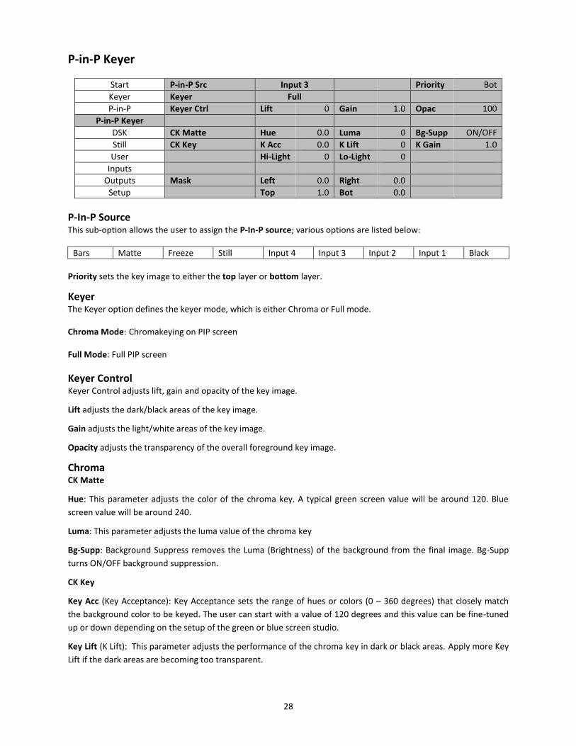
P-in-P Keyer
Start P-in-P Src Input 3 Priority Bot
Keyer Keyer Full
P-in-P Keyer Ctrl Lift 0 Gain 1.0 Opac 100
P-in-P Keyer
DSK CK Matte Hue 0.0 Luma 0 Bg-Supp ON/OFF
Still CK Key K Acc 0.0 K Lift 0 K Gain 1.0
User Hi-Light 0 Lo-Light 0
Inputs
Outputs Mask Left 0.0 Right 0.0
Setup Top 1.0 Bot 0.0
P-In-P Source This sub-option allows the user to assign the P-In-P source; various options are listed below:
Bars Matte Freeze Still Input 4 Input 3 Input 2 Input 1 Black
Priority sets the key image to either the top layer or bottom layer.
Keyer The Keyer option defines the keyer mode, which is either Chroma or Full mode.
Chroma Mode: Chromakeying on PIP screen
Full Mode: Full PIP screen
Keyer Control Keyer Control adjusts lift, gain and opacity of the key image.
Lift adjusts the dark/black areas of the key image.
Gain adjusts the light/white areas of the key image.
Opacity adjusts the transparency of the overall foreground key image.
Chroma CK Matte
Hue: This parameter adjusts the color of the chroma key. A typical green screen value will be around 120. Blue
screen value will be around 240.
Luma: This parameter adjusts the luma value of the chroma key
Bg-Supp: Background Suppress removes the Luma (Brightness) of the background from the final image. Bg-Supp
turns ON/OFF background suppression.
CK Key
Key Acc (Key Acceptance): Key Acceptance sets the range of hues or colors (0 – 360 degrees) that closely match
the background color to be keyed. The user can start with a value of 120 degrees and this value can be fine-tuned
up or down depending on the setup of the green or blue screen studio.
Key Lift (K Lift): This parameter adjusts the performance of the chroma key in dark or black areas. Apply more Key
Lift if the dark areas are becoming too transparent.

29
Key Gain (K Gain): This parameter adjusts the performance of the chroma key in light or white areas. Apply more
Key Gain if the light areas are becoming too transparent.
Hi-Light: Hi-light boosts the foreground key in high luminance area.
Lo-Light: Lo-light boosts the foreground key in low luminance area.
Mask The Mask feature allows the user to configure the Mask in chroma mode or full mode.
Left – Left sets the left edge of the P-in-P keyer mask.
Right – Right sets the right edge of the P-in-P keyer mask.
Top – Top sets the top edge of the P-in-P keyer mask.
Bottom – Bottom sets the bottom edge of the P-in-P keyer mask.
30
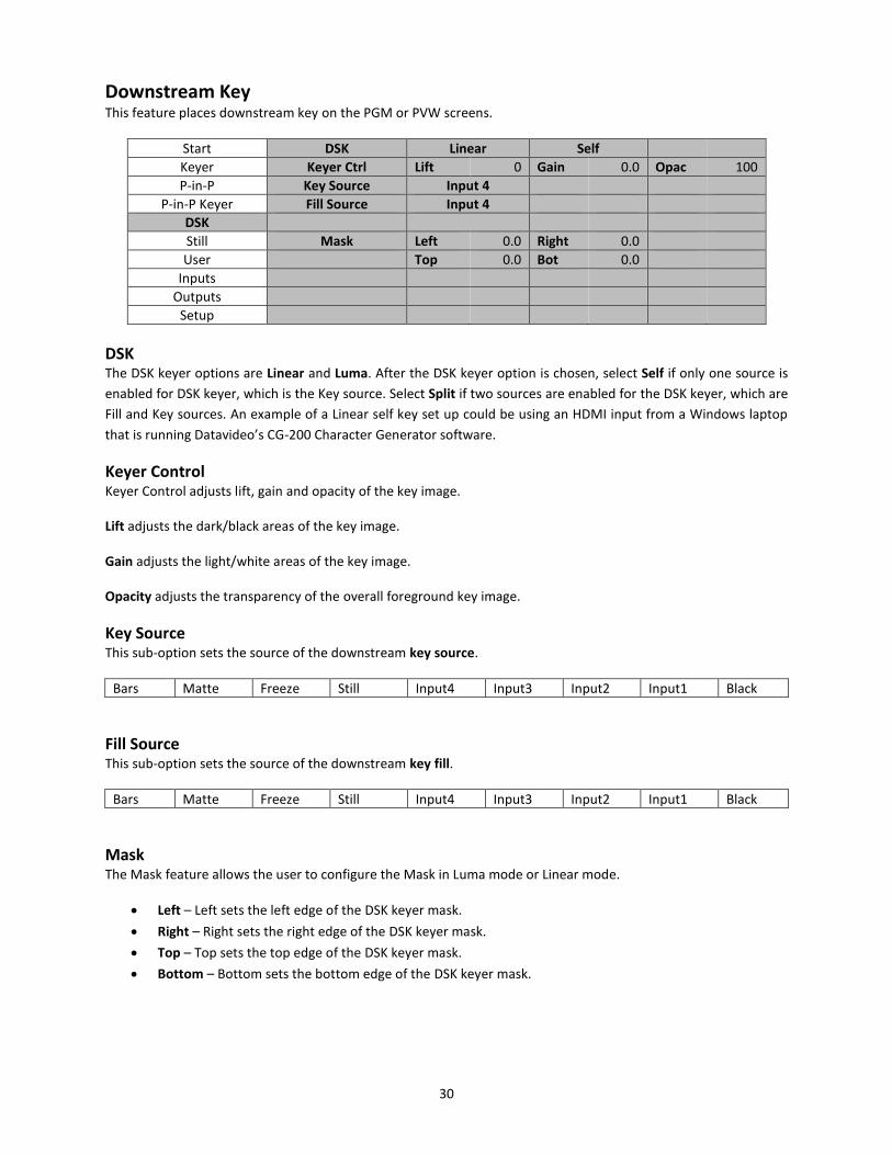
Downstream Key This feature places downstream key on the PGM or PVW screens.
Start DSK Linear Self
Keyer Keyer Ctrl Lift 0 Gain 0.0 Opac 100
P-in-P Key Source Input 4
P-in-P Keyer Fill Source Input 4
DSK
Still Mask Left 0.0 Right 0.0
User Top 0.0 Bot 0.0
Inputs
Outputs
Setup
DSK The DSK keyer options are Linear and Luma. After the DSK keyer option is chosen, select Self if only one source is
enabled for DSK keyer, which is the Key source. Select Split if two sources are enabled for the DSK keyer, which are
Fill and Key sources. An example of a Linear self key set up could be using an HDMI input from a Windows laptop
that is running Datavideo’s CG-200 Character Generator software.
Keyer Control Keyer Control adjusts lift, gain and opacity of the key image.
Lift adjusts the dark/black areas of the key image.
Gain adjusts the light/white areas of the key image.
Opacity adjusts the transparency of the overall foreground key image.
Key Source This sub-option sets the source of the downstream key source.
Bars Matte Freeze Still Input4 Input3 Input2 Input1 Black
Fill Source This sub-option sets the source of the downstream key fill.
Bars Matte Freeze Still Input4 Input3 Input2 Input1 Black
Mask The Mask feature allows the user to configure the Mask in Luma mode or Linear mode.
Left – Left sets the left edge of the DSK keyer mask.
Right – Right sets the right edge of the DSK keyer mask.
Top – Top sets the top edge of the DSK keyer mask.
Bottom – Bottom sets the bottom edge of the DSK keyer mask.

31
Still Still allows the user to load images from the memory, save images to the memory, and save the images captured.
Start Load Still Still 80 Load Freeze
Keyer
P-in-P Save Still Freeze Save Still 80
P-in-P Keyer
DSK Freeze 1 Live 2 Live 3 Live
Still 4 Live Freeze Still
User
Inputs
Outputs
Setup
Load Still Upon selecting “Load Still”, the user can then choose the memory location from which the still image is loaded. The following are the destinations to which the still image can be loaded:
Freeze
Input 4
Input 3
Input 2
Input 1
Still FS3
Still FS2
Still FS1
Select “Load” to load the still image to the determined destination.
Save Still “Save Still” allows the user to save the still image to a specific memory location. The user should determine the source of the still image first. The available sources are listed below:
Freeze
Input 4
Input 3
Input 2
Input 1
Still FS3
Still FS2
Still FS1
To complete the save, the user can simply select “Save” after determining the memory location.
Freeze “Freeze” allows the user to load an image to Inputs 1-4 from one of the four sources listed as follows:
Clip
Still
Freeze
Live “Freeze” also allows the user to load an image to the “Freeze” window from one of the two sources listed as follows:
Clip
Still

32
User In this option, the user is allowed to load previously saved settings and save the currently configured settings.
Start Load Mem Memory 13 Load
Keyer
P-in-P Save Mem Memory 13 Save
P-in-P Keyer
DSK
Still
User
Inputs
Outputs
Setup
Load Memory Use the up/down arrow to scroll to the desired memory location and load the saved setting by selecting “Load”
Save Memory Use the up/down arrow to scroll to the desired memory location and save the current setting by selecting “Save”
Inputs This feature allows the user to configure the color of the Inputs 1-4. In addition, the user can shuffle the contents
between Inputs 1-4, Still and Freeze.
Start Input 1 Black 0 White 100 Chrom 1.0
Keyer Input 2 Black 0 White 100 Chrom 1.0
P-in-P Input 3 Black 0 White 100 Chrom 1.0
P-in-P Keyer Input 4 Black 0 White 100 Chrom 1.0
DSK
Still Crosspoint 1 Input 1 2 Input 2 3 Input 3
User 4 Input 4 5 Still 6 Freeze
Inputs
Outputs
Setup
Input 1-4 By selecting the corresponding input (Inputs 1-4), the user will then be allowed to configure the colour of the input
1-4 by adjusting its Black Level, White Clip and Chroma Gain parameters.
Crosspoint Crosspoint gives the user the ability to shuffle the contents between Inputs 1-4, Still and Freeze. In other words,
the user will be able to assign any of the sources of Inputs 1-4, Still and Freeze to the 6 input buttons (1, 2, 3, 4, Still
and Freeze) of the Program and Preset rows as desired.
33
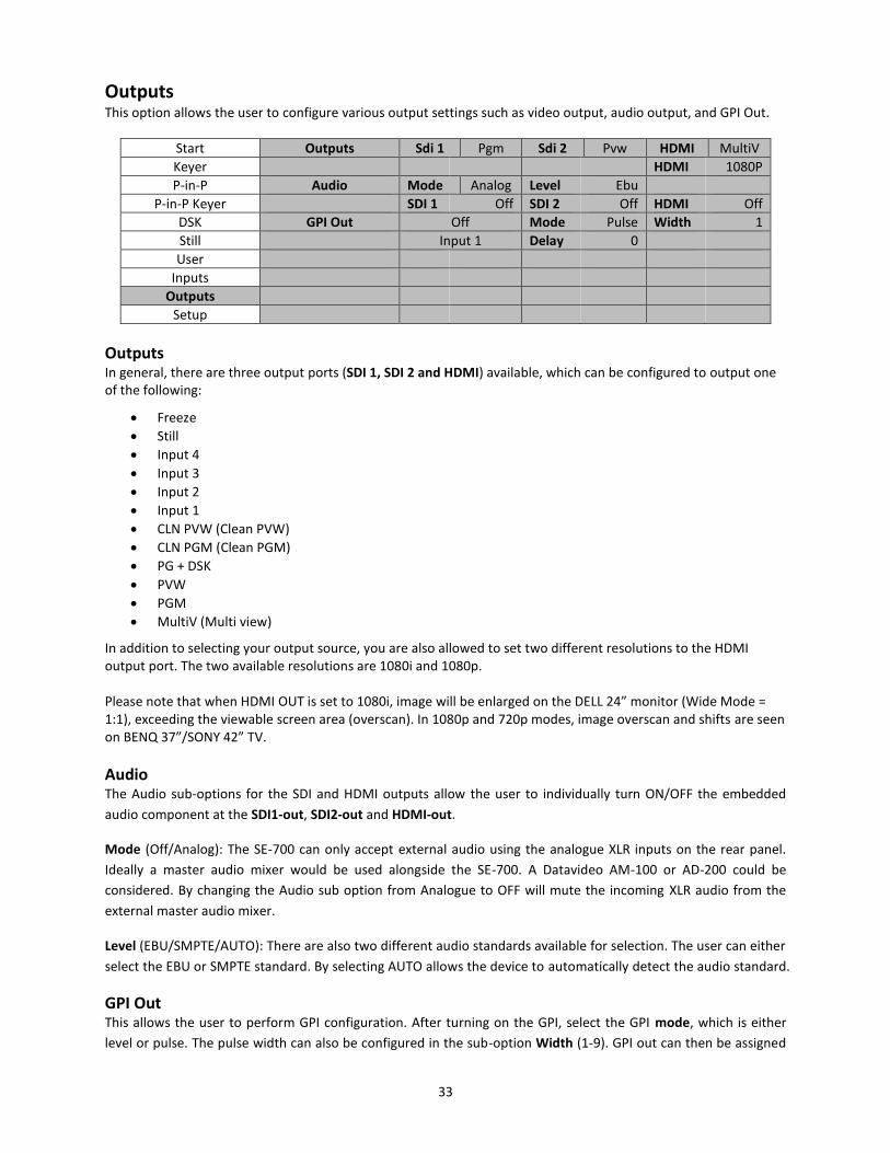
Outputs This option allows the user to configure various output settings such as video output, audio output, and GPI Out.
Start Outputs Sdi 1 Pgm Sdi 2 Pvw HDMI MultiV
Keyer HDMI 1080P
P-in-P Audio Mode Analog Level Ebu
P-in-P Keyer SDI 1 Off SDI 2 Off HDMI Off
DSK GPI Out Off Mode Pulse Width 1
Still Input 1 Delay 0
User
Inputs
Outputs
Setup
Outputs In general, there are three output ports (SDI 1, SDI 2 and HDMI) available, which can be configured to output one of the following:
Freeze
Still
Input 4
Input 3
Input 2
Input 1
CLN PVW (Clean PVW)
CLN PGM (Clean PGM)
PG + DSK
PVW
PGM
MultiV (Multi view)
In addition to selecting your output source, you are also allowed to set two different resolutions to the HDMI output port. The two available resolutions are 1080i and 1080p. Please note that when HDMI OUT is set to 1080i, image will be enlarged on the DELL 24” monitor (Wide Mode = 1:1), exceeding the viewable screen area (overscan). In 1080p and 720p modes, image overscan and shifts are seen on BENQ 37”/SONY 42” TV.
Audio The Audio sub-options for the SDI and HDMI outputs allow the user to individually turn ON/OFF the embedded
audio component at the SDI1-out, SDI2-out and HDMI-out.
Mode (Off/Analog): The SE-700 can only accept external audio using the analogue XLR inputs on the rear panel.
Ideally a master audio mixer would be used alongside the SE-700. A Datavideo AM-100 or AD-200 could be
considered. By changing the Audio sub option from Analogue to OFF will mute the incoming XLR audio from the
external master audio mixer.
Level (EBU/SMPTE/AUTO): There are also two different audio standards available for selection. The user can either
select the EBU or SMPTE standard. By selecting AUTO allows the device to automatically detect the audio standard.
GPI Out This allows the user to perform GPI configuration. After turning on the GPI, select the GPI mode, which is either
level or pulse. The pulse width can also be configured in the sub-option Width (1-9). GPI out can then be assigned

34
to one of Inputs 1-4 and the delay can be set to between 1 and 99. This feature could be used to trigger playback
from an external playback device such as Datavideo’s NVP-20 or HRS-30 unit.
Setup In the “Setup” menu, the user can change the resolution, adjust the menu preferences, upgrade firmware and
view the current firmware versions (Interface, Mainboard and Keyboard).
Start Standard 1080i/59.94 Save
Keyer
P-in-P Menu Pref Blue Transp 0 Size Normal
P-in-P Keyer Menu Pos Centre
DSK
Still Software Upgrade (Available only when the USB storage device containing the latest firmware file is inserted)
User
Inputs
Outputs
Setup s/w: v1.0.0.0 f/w: 2015-06-05 Kbd: v2.14
Standard This option allows the user to choose the appropriate output resolution such as 1080i/50. Once done, simply select
“Save” to confirm the selected output resolution. The available resolutions are 1080i/50/59.94/60, 720p/60/59.94/50.
Menu Preference In menu preference, the user is allowed to set the menu color, menu transparency level, menu size and the
display position.
Menu color: the available options are blue and grey Options of Menu Transparency are listed below: 0: No Transparency 1: Background 50% Transparent (buttons not Transparent) 2: All Menu 50% Transparent Menu Size The menu size options are: 1. Normal 2. Small (1080i Mode) 3. Large (720p Mode) Menu Postion Menu Position gives the user ability to select several positions for the Menu area on the Screen. The current options are Centre, Top, Left, Right and Bottom
Software This option is only available when the USB storage device containing the latest firmware file is inserted. Select
Upgrade to start the firmware upgrade process. Refer to the FIRMWARE UPGRADE section for more details.
At the bottom of the menu, you will be able to view the version number of the latest firmware installed.
35
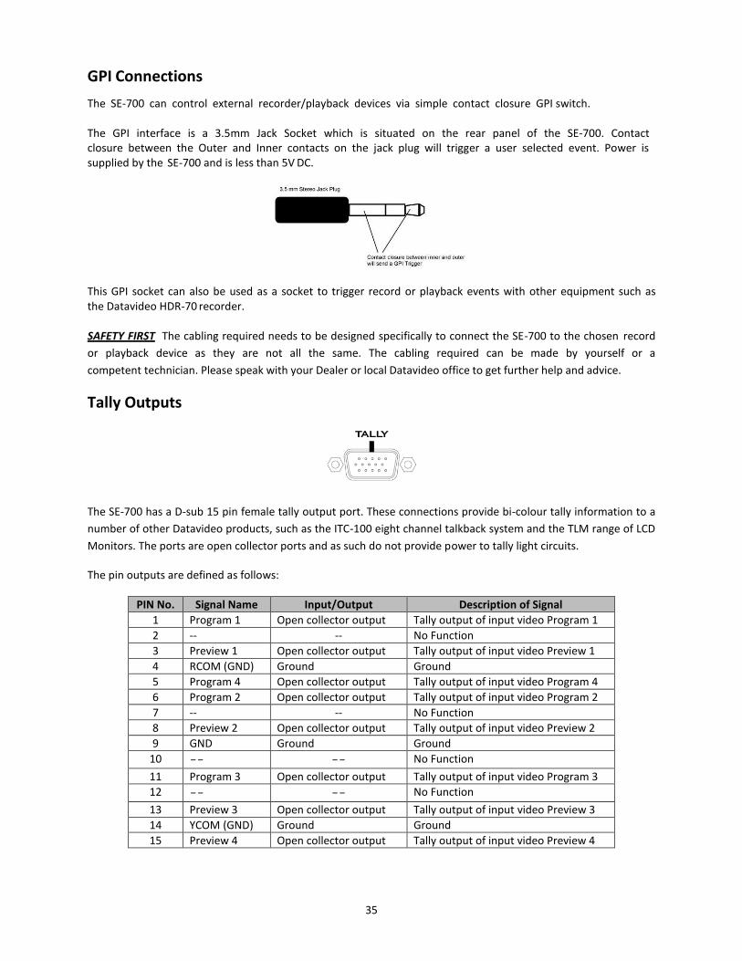
GPI Connections
The SE-700 can control external recorder/playback devices via simple contact closure GPI switch. The GPI interface is a 3.5mm Jack Socket which is situated on the rear panel of the SE-700. Contact closure between the Outer and Inner contacts on the jack plug will trigger a user selected event. Power is supplied by the SE-700 and is less than 5V DC.
This GPI socket can also be used as a socket to trigger record or playback events with other equipment such as the Datavideo HDR-70 recorder. SAFETY FIRST The cabling required needs to be designed specifically to connect the SE-700 to the chosen record
or playback device as they are not all the same. The cabling required can be made by yourself or a
competent technician. Please speak with your Dealer or local Datavideo office to get further help and advice.
Tally Outputs
The SE-700 has a D-sub 15 pin female tally output port. These connections provide bi-colour tally information to a
number of other Datavideo products, such as the ITC-100 eight channel talkback system and the TLM range of LCD
Monitors. The ports are open collector ports and as such do not provide power to tally light circuits.
The pin outputs are defined as follows:
PIN No. Signal Name Input/Output Description of Signal
1 Program 1 Open collector output Tally output of input video Program 1
2 -- -- No Function
3 Preview 1 Open collector output Tally output of input video Preview 1
4 RCOM (GND) Ground Ground
5 Program 4 Open collector output Tally output of input video Program 4
6 Program 2 Open collector output Tally output of input video Program 2
7 -- -- No Function
8 Preview 2 Open collector output Tally output of input video Preview 2
9 GND Ground Ground
10 -- -- No Function
11 Program 3 Open collector output Tally output of input video Program 3
12 -- -- No Function
13 Preview 3 Open collector output Tally output of input video Preview 3
14 YCOM (GND) Ground Ground
15 Preview 4 Open collector output Tally output of input video Preview 4

36
Firmware Upgrade
1. Locate the FW Upgrade USB port on the back panel of the SE-700
2. Insert the USB stick that contains the latest firmware to the FW upgrade port 3. Power on the device and the device should automatically detect the connected USB storage device 4. Press the “MENU” button on the control panel to open the menu on the monitor screen 5. Press the “ENTER” button on the control panel to browse through the menu using the arrow buttons on the
control panel 6. Press the “down arrow” button to scroll to the “Setup” Option 7. Press the “ENTER” button again to enter the “Setup” menu 8. Press the “down arrow” button to scroll to the “Software” Sub-option and then press the “ENTER” button to
select the “Software” Sub-option 9. Press the “right arrow” button to scroll to “Upgrade” and then press the “ENTER” button to start the upgrade
process 10. Reboot the device after the upgrade process is complete (background of the “Upgrade” turns from red to
green)
Steps 11-13 are applicable if the kbd firmware is updated.
11. After the device is rebooted, the user will first see the color LED of the program and preset rows lights up one after one, which means that the device is updating the control panel firmware automatically.
12. After the control panel firmware is updated successfully, all color LEDs will start to flash, indicating the completion of all firmware upgrade.
13. Reboot the device again to complete the firmware upgrade process

37
Frequently-Asked Questions This section describes problems that you may encounter while using the SE-700. If you have questions, please refer
to related sections and follow all the suggested solutions. If problem still exists, please contact your distributor or
the service center.
How to use the P-in-P Keyer function?
1. Connect a source with a green backdrop 2. Press and hold “PIP PVW” button and select an input source from the preset row 3. Press “PIP PGM” button to open the PIP window on PGM Screen 4. Press “PIP SETUP” button to open the P-in-P Setting window 5. Set the XY coordinates and the PIP window size to your preference 6. Go to P-in-P Keyer setting menu and configure the following to achieve chromakeying of the green backdrop
P-in-P Src: Select an input source
Keyer: Chroma
Keyer CTRL: Lift 0 / Gain 0 / OPAC 100
CK Matte: HUE 120~125 / LUMA 100
CK Key: K ACC 140 / K Lift 10 / K Gain 16
How to use the Keyer function?
1. Connect a source with a green backdrop 2. Press and hold “KEYER PVW” button and select an input source from the preset row 3. Press “KEYER PGM” button to display the selected source on PGM Screen 4. Press “KEYER SETUP” button to open the Keyer Setting window 5. Configure the following to achieve chromakeying of the green backdrop
Keyer: Chroma
Keyer CTRL: Lift 0 / Gain 0 / OPAC 100
CK Matte: HUE 120~125 / LUMA 100
CK Key: K ACC 140 / K Lift 10 / K Gain 16
Can we save the PGM image captured using the GRAB function to the SD card?
Currently the PGM image captured using the GRAB function is saved temporarily to INPUT 6 and will be lost once the SE-700 is powered off. Future firmware release will allow the user to permanently save the PGM image captured using the GRAB function to the SD card.
How to import logo on the SE-700?
The SE-700 does not have the feature for importing the logo, you can upload the logo using Luma Keyer or DSK Keyer.
Why can’t I use the SE-700 Wipe Position function?
The SE-700 Wipe Position function is only supported in Wipe Mode.
Why Still Frame Store does not have the memory function?
You can store a still image to any of the three Still Frame Stores (FS1-FS3), and then save it to the User Memory. Reboot the SE-700 and then load the saved still image to the Still Frame Store.
I want to keep my settings after I reboot the SE-700.
You need to execute setup/save on the SE-700. All parameters can be saved in memory 0 under the option “user/save Mem”. In this way, the parameters can be kept even after the SE-700 is rebooted.
The SE-700 cannot be powered on if the power is cut during the FW update using the USB Dongle.

38
If the power is cut or the device is switched off while the firmware is being updated (SE-700 M/B/setup/upgrade), this will cause corrupted data on the SD Card and thus the SE-700 will then fail to boot. The SD card will need to be re-programmed.
I cannot roll back to older SE-700 SW versions.
Yes, this is because the system structure has been modified, if you have used SE-700_v0.9.9.4 and above, you will not be able to roll back to older versions.
On the control panel, F3 button does not have any function.
F3 button has been defined as “Restoring to Default” in V_1.0.0.0.
i. Pressing F3 button while in the second level sub-option of one particular function resets all parameters of that sub-option to default.
ii. Pressing F3 button in the first level option of that particular function resets all parameters of that option to default.
What are the options under Outputs/Audio/Level in the MENU?
AUTO, SMPTE and EBU are the three sub-options available for the option Analog Audio Level. Three different digital audio level specifications give the user flexibility to choose whether to use the American Standard or the European Standard. If AUTO is selected, then the SE-700 will automatically use
i. SMPTE SPEC (-24 dBFS) when the resolution settings are 1080i/59.94/60 and 720P/59/60; and ii. EBU SPEC (-18 dBFS) when the resolution settings are 1080i/50 and 720p/50.
Under the option Setup/Standard, 1080i/50 mode is selected and nothing is seen on the HDMI output to Datavideo’s TVS-1000.
When the SE-700 is set to 1080i, the HDMI output resolution will be set to 1080p, which is not supported on the TVS-1000 and this is why you cannot see anything on the screen.
Under the option Outputs/HDMI PORT, assign the output to be PGM SOURCE but it will be automatically switched back multiviewer.
The SE-700 output consists of two SDI OUT and one HDMI OUT, and if the system detects that all three outputs are set to sources other than multiviewer, the system will then force to reset the HDMI OUT to multiviewer.
When PIP PGM and PIP PVW buttons are turned on at the same time, PIP is not displayed on PVW screen, and if only the PIP PGM button is turned on, PIP is seen on both PGM and PVW screens. The same issue occurs in KEYER and DSK.
The SE-700 exhibits different behaviors from the SE-2200.
Turning on PIP PVW/LUMA PVW/DSK PVW displays the effect on the PVW screen. Turns on the PVW, and after the effect is configured, turn on PIP PGM/LUMA PGM/DSK PGM and then the effect will be taken to PGM view. (The user can also use the CUT button or T-BAR to perform the transition. If only the PIP PGM/LUMA PGM/DSK PGM is turned on, you will see the effect on both PVW and PGM views.)
PIP image does not fill the PIP screen.
When X = 0, Y = 0, and Size = 100%, PIP image fails to fully fill the PIP screen (or the initial position is incorrect), a few lines will appear at the bottom and when switched to underscan mode, the background image can be seen through at the top and bottom of the PIP screen.
39
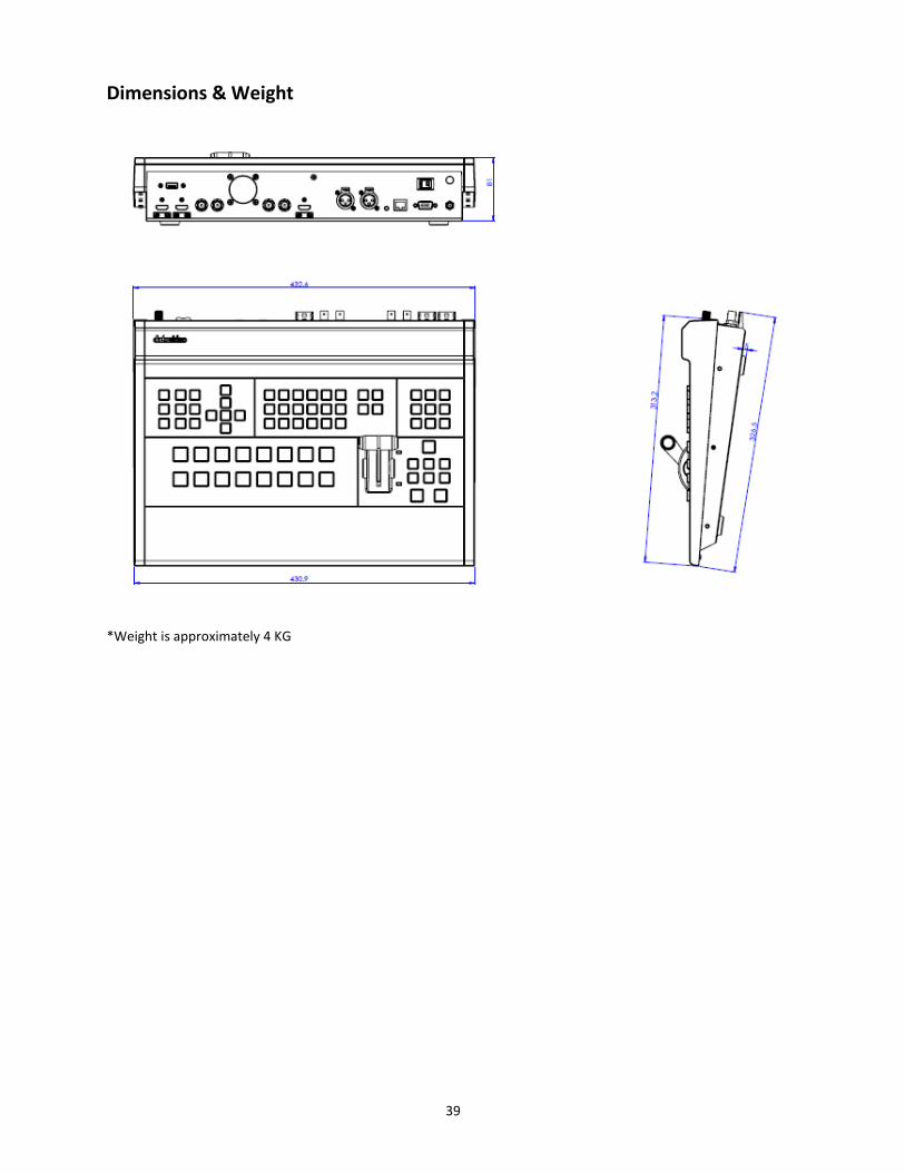
Dimensions & Weight
*Weight is approximately 4 KG

40
Specifications
Connections
Total Video Inputs 2 HDMI( ver1.3a) + 2 SDI
Total Outputs 1 HDMI (Ver 1.3a ) + 2 SDI
SDI Video Input 2 ( 1080i / 720p )
HDMI Video Input 2 x HDMI(RGB/YUV)
1080i / 720p
SDI Audio Output (PGM output) 2CH
Analog Audio Input 2CH XLR
Internal Frame Synchronizers 4 All Inputs
PGM Out HDMI / SDI
Multi view Out HDMI (720P -> 720P ; 1080i->1080P)
SDI (720P -> 720P ; 1080i->1080i)
Output can select any of input source
PROGRAM (w/ DSK) Clean PROGRAM
PREVIEW ( w/o DSK) MULTISCREEN
Input 1~4
Audio Indicator on Multi view Y ( output 2CH)
Tally Out Y
GPI Y (Level / Pulse Trigger selectable)
Software Updates Ethernet
Standards
HD Format Support 1080i/50, 1080i/59.94, 1080i/60, 720p/50, 720p/59.94, 720p/60
SDI Compliance SMPTE 292M.( SDI output /PGM out)
Video Sampling 4:2:2 10 bit
Color Precision 4:2:2 10 bit
Color Space 4:2:2 YUV
HDMI Input Resolutions for Computers 1280 x 720 59.94Hz 50Hz (720P) and
1920 x 1080 59.94Hz 50Hz (1080p & 1080i)
Processing
Colorspace Conversion Hardware based real time
Processing Delay < 1 frame
Audio Mixer selectable audio follow video
master gain control
Extras
Downstream Keyers 1
Linear/Luma Keyers 3 (M/E Keyer, PIP, DSK)
Chroma Keyers 1 Upstream Keyer
1 Upstream PIP
Pattern Generators Color Bar
PIP 1
41
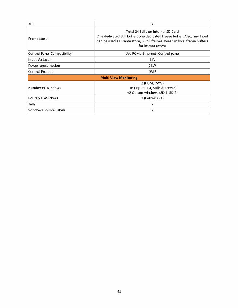
XPT Y
Frame store
Total 24 Stills on Internal SD Card One dedicated still buffer, one dedicated freeze buffer. Also, any Input can be used as Frame store, 3 Still frames stored in local frame buffers
for instant access
Control Panel Compatibility Use PC via Ethernet; Control panel
Input Voltage 12V
Power consumption 23W
Control Protocol DVIP
Multi View Monitoring
Number of Windows 2 (PGM, PVW)
+6 (Inputs 1-4, Stills & Freeze) +2 Output windows (SDI1, SDI2)
Routable Windows Y (Follow XPT)
Tally Y
Windows Source Labels Y

42
Notes

43
Notes
44
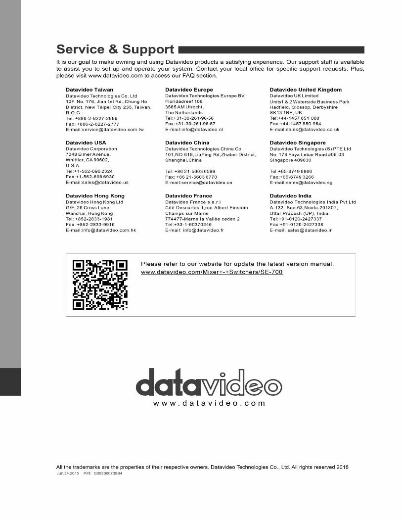
Service and Support