Datavideo SE-2200 6 input HD broadcast quality switcher
32
-
Upload
av-profshop -
Category
Technology
-
view
360 -
download
1
Transcript of Datavideo SE-2200 6 input HD broadcast quality switcher


2
Contents
Warranty ........................................................................................................................................................ 3
Disposal ......................................................................................................................................................... 3
Packing List ................................................................................................................................................... 4
Connection of SE-2200 ................................................................................................................................. 4
Main Unit – Front Panel................................................................................................................................. 5
Main Unit - Rear Panel .................................................................................................................................. 5
Rear Panel Connections .......................................................................................................................... 6
Control Panel ................................................................................................................................................. 8
Keyboard Controls ................................................................................................................................... 9
Menu Options .............................................................................................................................................. 14
How to use the CG-200 software with SE-2200 ......................................................................................... 16
SE-2200 Video Layers ................................................................................................................................. 19
Picture in Picture Function ......................................................................................................................... 20
PIP Settings .......................................................................................................................................... 20
PIP Preset and PIP Program ................................................................................................................. 20
Assigning a video source input to a PIP ................................................................................................. 20
DSK Function .............................................................................................................................................. 21
AUDIO Function ........................................................................................................................................... 22
AUDIO FOLLOW VIDEO ....................................................................................................................... 23
AUDIO FIXED ....................................................................................................................................... 23
Audio Menu Options – De-embedding SDI or HDMI audio .................................................................... 24
Working with a fixed or single audio source ........................................................................................... 25
Switching between different embedded audio sources .......................................................................... 25
How to Re-calibrate the SE-2200 T-Bar ...................................................................................................... 26
GPI Connections ......................................................................................................................................... 27
SE-2200 Tally Outputs................................................................................................................................. 27
Example SE-2200 Set Up ............................................................................................................................ 28
Dimensions .................................................................................................................................................. 29
Specifications .............................................................................................................................................. 30
Service and Support ................................................................................................................................... 32
3
Warranty
Standard Warranty
Datavideo equipment is guaranteed against any manufacturing defects for one year from the date of purchase.
The original purchase invoice or other documentary evidence should be supplied at the time of any request for
repair under warranty.
Damage caused by accident, misuse, unauthorized repairs, sand, grit or water is not covered by this warranty.
All mail or transportation costs including insurance are at the expense of the owner.
All other claims of any nature are not covered.
Cables & batteries are not covered under warranty.
Warranty only valid within the country or region of purchase.
Your statutory rights are not affected.
Two Year Warranty
All Datavideo products purchased after 01-Oct.-2008 qualify for a free one year extension to the standard
Warranty, providing the product is registered with Datavideo within 30 days of purchase. For information on how
to register please visit www.datavideo.com or contact your local Datavideo office or authorized Distributors
Certain parts with limited lifetime expectancy such as LCD Panels, DVD Drives, Hard Drives are only covered
for the first 10,000 hours, or 1 year (whichever comes first).
Any second year warranty claims must be made to your local Datavideo office or one of its authorized Distributors
before the extended warranty expires.
Disposal
For EU Customers only - WEEE Marking
This symbol on the product indicates that it will not be treated as household waste. It must
be handed over to the applicable take back scheme for the recycling of electrical and
electronic equipment. For more detailed information about the recycling of this product,
please contact your local Datavideo office.

4
Packing List
1 x SE-2200 Main Unit
1 x SE-2200 Control Panel / Keyboard
1 x SE-2200 Quick Start Guide
1 x Accessory List
Connection of SE-2200
Use D-SUB Cable to connect SE-2200 main unit to SE-2200 control unit.
SE-2200 Control Unit
SE-2200 Main Unit
D-Sub Cable

5
Main Unit – Front Panel
The front panel on the SE-2200 main unit has a grille for airflow cooling fans. Please do not block or cover this grille as the unit may overheat. This grille should also be kept free of dust. The front panel can be removed by using the four thumbscrews. A soft brush or cloth can then be used to clean the grille before attaching it back to the unit.
The power button starts and shuts down both the SE-2200 main unit and its attached keyboard.
Main Unit - Rear Panel
1. Video Input 1~4 – HD-SDI 9. Grounding Terminal
2. Tally Output Connector 10. 4pin XLR Power Input Connector
3. Connect the SE-2200 Keyboard 11. Mini Switch 2
4. Ethernet Port for PC Control & Updates (TBD) 12. Ethernet Port for Load file & Firmware Updates
5. RS-232/422 Connector & Mini Switch 1 (TBD) 13. Multi View Outputs – HDMI
6. GPI Output Connector 14. Video Output 1~6 – HD-SDI
7. 3pin XLR Audio Inputs 1~4 15. Input 6 – HD-SDI / HDMI (See page 6)
8. 3pin XLR Audio Outputs 1,2 16. Input 5 – HD-SDI / HDMI (See page 6)
1 2 3 4 5 6 7 8
9 10 11 12 13
14 15 16
6
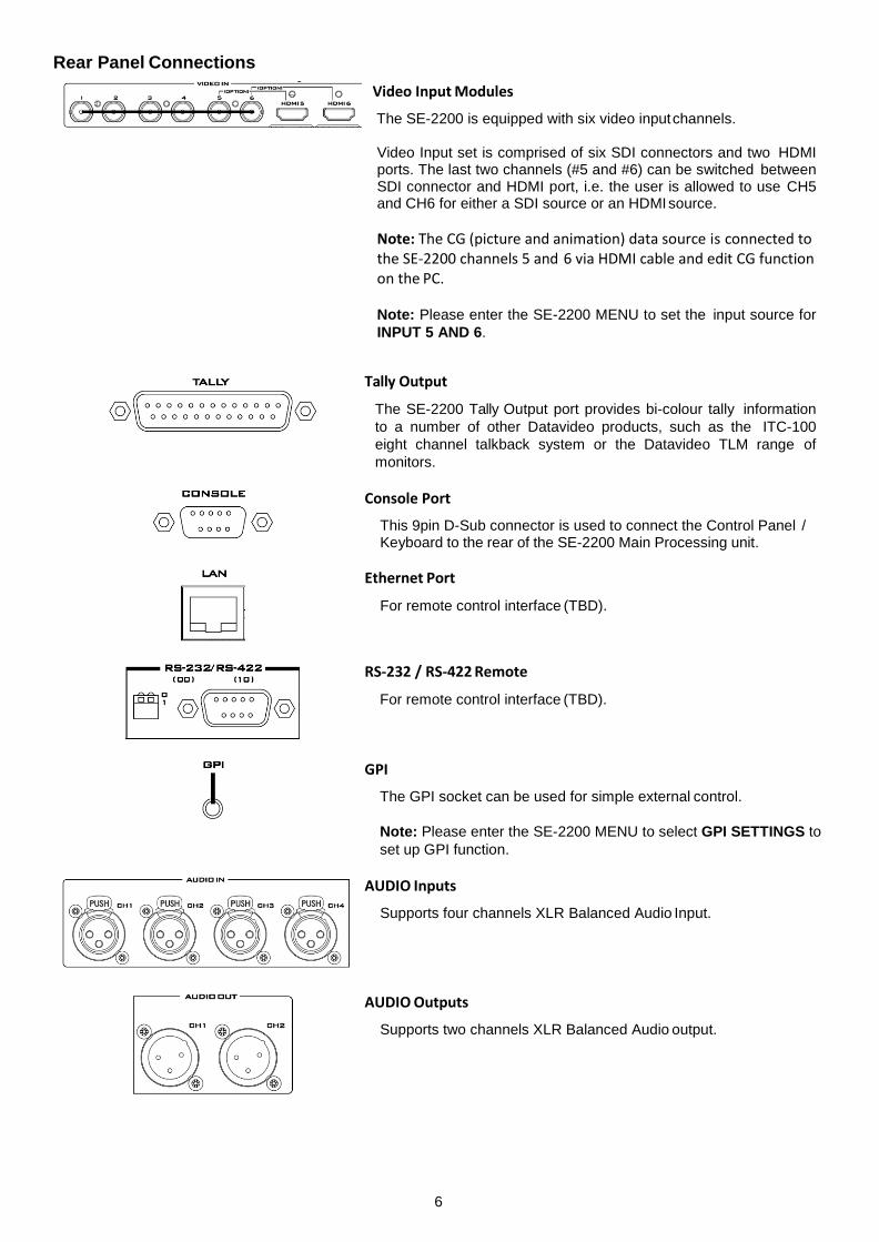
Rear Panel Connections
Video Input Modules
The SE-2200 is equipped with six video input channels.
Video Input set is comprised of six SDI connectors and two HDMI ports. The last two channels (#5 and #6) can be switched between SDI connector and HDMI port, i.e. the user is allowed to use CH5 and CH6 for either a SDI source or an HDMI source.
Note: The CG (picture and animation) data source is connected to the SE-2200 channels 5 and 6 via HDMI cable and edit CG function on the PC.
Note: Please enter the SE-2200 MENU to set the input source for
INPUT 5 AND 6.
Tally Output
The SE-2200 Tally Output port provides bi-colour tally information
to a number of other Datavideo products, such as the ITC-100
eight channel talkback system or the Datavideo TLM range of
monitors.
Console Port
This 9pin D-Sub connector is used to connect the Control Panel / Keyboard to the rear of the SE-2200 Main Processing unit.
Ethernet Port
For remote control interface (TBD).
RS-232 / RS-422 Remote
For remote control interface (TBD).
GPI
The GPI socket can be used for simple external control.
Note: Please enter the SE-2200 MENU to select GPI SETTINGS to
set up GPI function.
AUDIO Inputs
Supports four channels XLR Balanced Audio Input.
AUDIO Outputs
Supports two channels XLR Balanced Audio output.

7
Grounding Terminal
When connecting this unit to any other component, make sure that it is properly grounded by connecting this terminal to an appropriate point. When connecting, use the socket and be sure to use wire with a cross-sectional area of at least 1.0 mm
2.
DC Input
Connect the supplied 12V 3A PSU to this 4pin XLR socket.
Pin 1 = GND ( - ) Pin 2 = NC Pin 3 = NC Pin 4 = VCC ( + )
Mini Switch 2
Firmware upgrade switch (The two DIP switches must be set to the UP position).
Service Port
This RJ45 Ethernet port is used for updating the SE-2200
firmware, or uploading logo image.
SDI Video Outputs
The six BNC output connectors are user defined SDI outputs. Each of these SDI outputs has the option to be:
1. Program 2. Program logo free 3. Program logo & titles free 4. Preview 5. Aux1,2,3 or 4 6. Multi screen
Note: Please enter the SE-2200 MENU to set the OUTPUT SOURCE.
HDMI Multi-View Outputs
SE-2200 is capable of achieving multi-view monitoring by
connecting two multi-view monitors to the two HDMI ports. The
two HDMI outputs can be used for monitoring video and audio in a
number of different configurations.
The HDMI connectors are located on the rear panel.
Note: HDMI multi-view output format is 1080i.
8
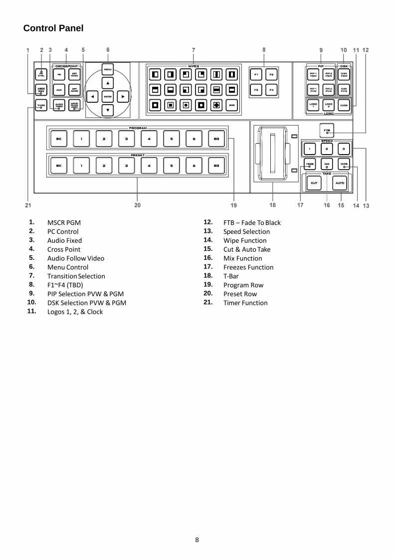
Control Panel
1. MSCR PGM 12. FTB – Fade To Black
2. PC Control 13. Speed Selection
3. Audio Fixed 14. Wipe Function
4. Cross Point 15. Cut & Auto Take
5. Audio Follow Video 16. Mix Function
6. Menu Control 17. Freezes Function
7. Transition Selection 18. T-Bar 8. F1~F4 (TBD) 19. Program Row
9. PIP Selection PVW & PGM 20. Preset Row
10. DSK Selection PVW & PGM 21. Timer Function
11. Logos 1, 2, & Clock

9
Keyboard Controls
Program and Preset rows
The Program row of buttons is the active channel, this is the live output. The active channel will appear as the
Program Output. You can switch or CUT from one video source to another directly on the Program row. You will see
the multi view Program output change as you press different keys along this top row of buttons.
The Preset row is the cued channel; this channel will appear in the Preview window. The Preset row selection decides
which input will be transitioned next when using any of the transition controls.
BK
Black background – the black background, for use on the Program and Preset row.
BG
Background button – assigns a background colour or colour bars for use on the Program and Preset row.
Note: Please enter the SE-2200 MENU and select CONSOLE SETTINGS to set the background colour.
MSCR/PGM
Switch the Multi Screen view or Program view.
Note: This function only works in 1080i mode.
PC Control
Press this key, via computer to control the SE-2200.
Audio Fixed
Manual selection of a mixed of audio channels fixed to a video channel at your choice.
For more detail, please see the AUDIO FIXED.
10
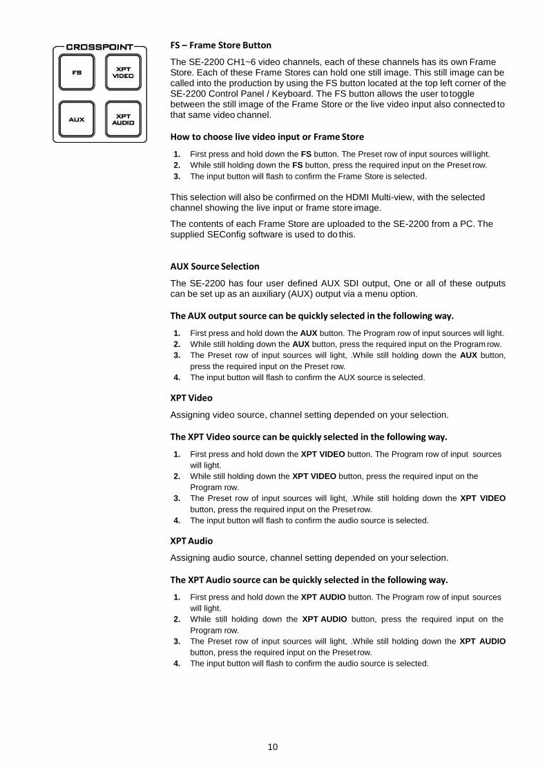
FS – Frame Store Button
The SE-2200 CH1~6 video channels, each of these channels has its own Frame Store. Each of these Frame Stores can hold one still image. This still image can be called into the production by using the FS button located at the top left corner of the SE-2200 Control Panel / Keyboard. The FS button allows the user to toggle between the still image of the Frame Store or the live video input also connected to that same video channel.
How to choose live video input or Frame Store
1. First press and hold down the FS button. The Preset row of input sources will light.
2. While still holding down the FS button, press the required input on the Preset row.
3. The input button will flash to confirm the Frame Store is selected.
This selection will also be confirmed on the HDMI Multi-view, with the selected channel showing the live input or frame store image.
The contents of each Frame Store are uploaded to the SE-2200 from a PC. The supplied SEConfig software is used to do this.
AUX Source Selection
The SE-2200 has four user defined AUX SDI output, One or all of these outputs can be set up as an auxiliary (AUX) output via a menu option.
The AUX output source can be quickly selected in the following way.
1. First press and hold down the AUX button. The Program row of input sources will light.
2. While still holding down the AUX button, press the required input on the Program row.
3. The Preset row of input sources will light, .While still holding down the AUX button,
press the required input on the Preset row.
4. The input button will flash to confirm the AUX source is selected.
XPT Video
Assigning video source, channel setting depended on your selection.
The XPT Video source can be quickly selected in the following way.
1. First press and hold down the XPT VIDEO button. The Program row of input sources
will light.
2. While still holding down the XPT VIDEO button, press the required input on the
Program row.
3. The Preset row of input sources will light, .While still holding down the XPT VIDEO
button, press the required input on the Preset row.
4. The input button will flash to confirm the audio source is selected.
XPT Audio
Assigning audio source, channel setting depended on your selection.
The XPT Audio source can be quickly selected in the following way.
1. First press and hold down the XPT AUDIO button. The Program row of input sources
will light.
2. While still holding down the XPT AUDIO button, press the required input on the
Program row.
3. The Preset row of input sources will light, .While still holding down the XPT AUDIO
button, press the required input on the Preset row.
4. The input button will flash to confirm the audio source is selected.

11
Audio Follow Video
Manual selection of one audio channel fixed to one video channel at your choice.
When you select video Channe1, the audio source and the video source will be synchronized on Channel 1.
Please see the AUDIO FOLLOW VIDEO (Page 23) for more details.
Menu Control
Press the MENU button in the SE-2200 function section to enter the System Configuration Menu. Press the UP, DOWN, LEFT, and RIGHT arrow buttons to navigate the menu options and to change values. Use the ENTER button to save and confirm any setting that has been amended.
WIPES
The SE-2200 has 17 user defined wipe buttons, and a BDR button.
All wipes can have an optional colour border applied. The wipe border width and colour are chosen within the menu system.
Transitions can be performed manually using the T-Bar or automatically by using the SPEED and AUTO TAKE buttons.
Vertical Wipe Left to Right. Vertical Wipe Right to Left.
Horizontal Wipe Top to Bottom. Horizontal Wipe Bottom to Top.
Box Wipe from outside edges to Centre. Box Wipe from Centre to outside edges.
Upper Left corner Wipe to Lower Right corner Upper Right corner Wipe to Lower Left corner.
Lower Left corner Wipe to Upper Right corner. Lower Right corner Wipe to Upper Left corner.
Circle Wipe from Centre to outside edges. Circle Wipe from outside edges to Centre.
Vertical Wipes from Centre to Left and Right sides.
Horizontal Wipes from Centre to Top and Bottom.
Vertical Wipes from Left and Right sides to Centre.
Horizontal Wipes from Top and Bottom to Centre.
Diamond Wipe from Centre to outside edges. Border: Enable / Disable wipe border
12
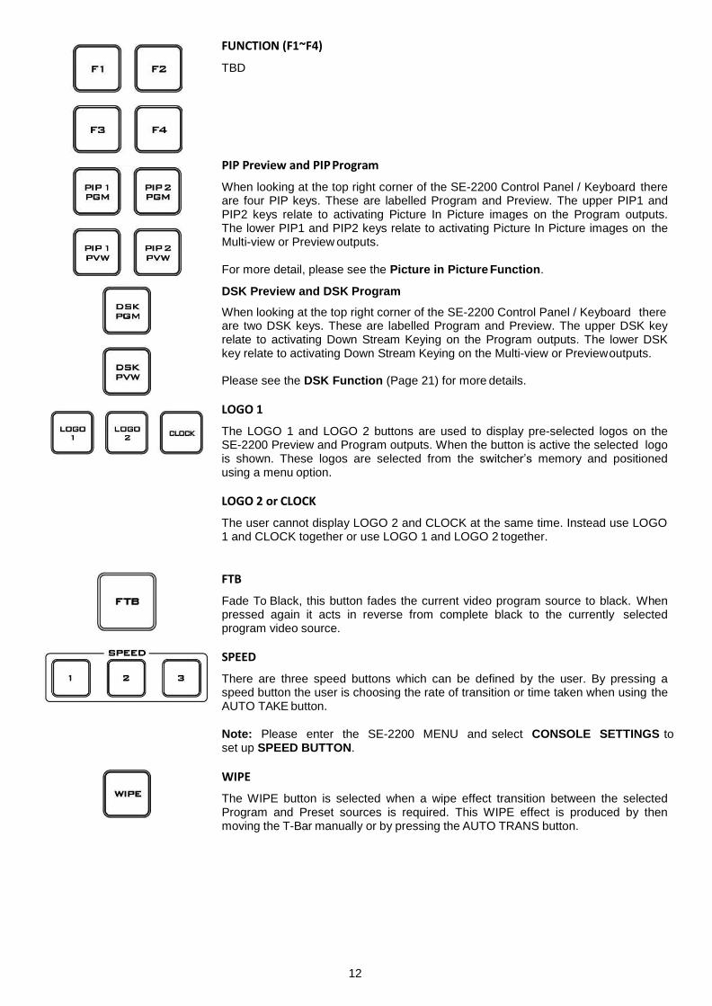
FUNCTION (F1~F4)
TBD
PIP Preview and PIP Program
When looking at the top right corner of the SE-2200 Control Panel / Keyboard there are four PIP keys. These are labelled Program and Preview. The upper PIP1 and PIP2 keys relate to activating Picture In Picture images on the Program outputs. The lower PIP1 and PIP2 keys relate to activating Picture In Picture images on the Multi-view or Preview outputs.
For more detail, please see the Picture in Picture Function.
DSK Preview and DSK Program
When looking at the top right corner of the SE-2200 Control Panel / Keyboard there are two DSK keys. These are labelled Program and Preview. The upper DSK key relate to activating Down Stream Keying on the Program outputs. The lower DSK key relate to activating Down Stream Keying on the Multi-view or Preview outputs.
Please see the DSK Function (Page 21) for more details.
LOGO 1
The LOGO 1 and LOGO 2 buttons are used to display pre-selected logos on the SE-2200 Preview and Program outputs. When the button is active the selected logo is shown. These logos are selected from the switcher’s memory and positioned using a menu option.
LOGO 2 or CLOCK
The user cannot display LOGO 2 and CLOCK at the same time. Instead use LOGO 1 and CLOCK together or use LOGO 1 and LOGO 2 together.
FTB
Fade To Black, this button fades the current video program source to black. When pressed again it acts in reverse from complete black to the currently selected program video source.
SPEED
There are three speed buttons which can be defined by the user. By pressing a speed button the user is choosing the rate of transition or time taken when using the AUTO TAKE button.
Note: Please enter the SE-2200 MENU and select CONSOLE SETTINGS to set up SPEED BUTTON.
WIPE
The WIPE button is selected when a wipe effect transition between the selected Program and Preset sources is required. This WIPE effect is produced by then moving the T-Bar manually or by pressing the AUTO TRANS button.
13
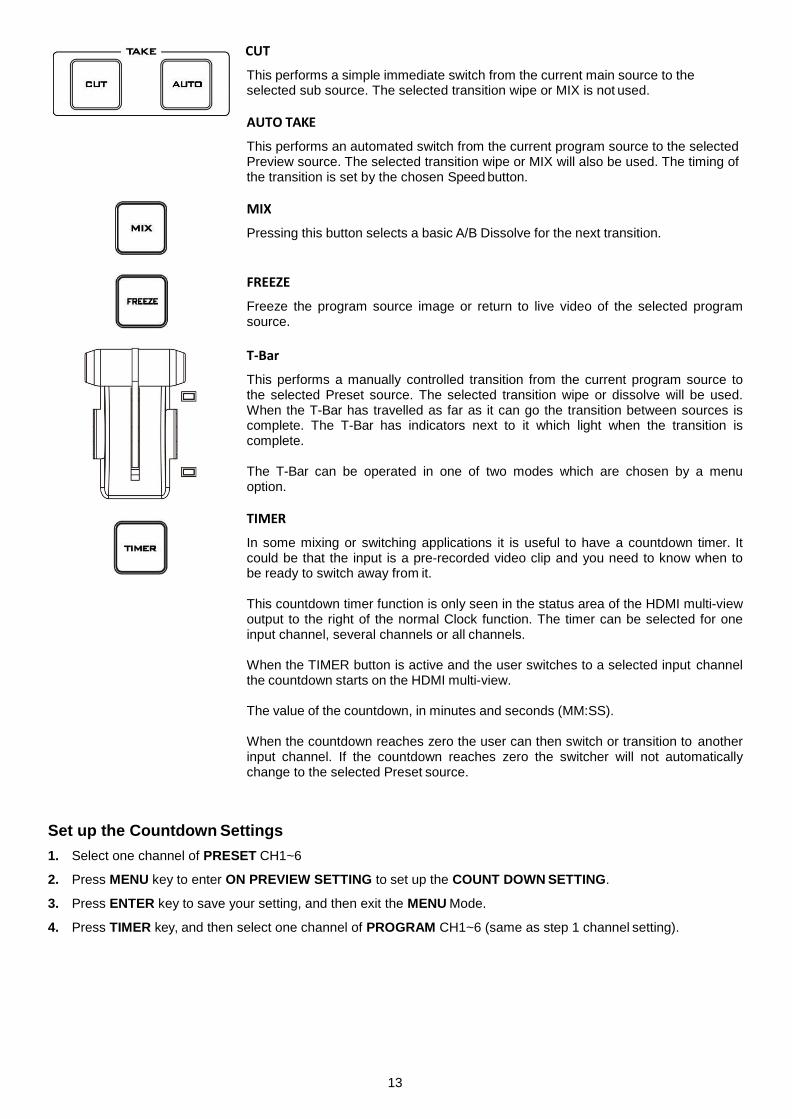
CUT
This performs a simple immediate switch from the current main source to the selected sub source. The selected transition wipe or MIX is not used.
AUTO TAKE
This performs an automated switch from the current program source to the selected Preview source. The selected transition wipe or MIX will also be used. The timing of the transition is set by the chosen Speed button.
MIX
Pressing this button selects a basic A/B Dissolve for the next transition.
FREEZE
Freeze the program source image or return to live video of the selected program source.
T-Bar
This performs a manually controlled transition from the current program source to the selected Preset source. The selected transition wipe or dissolve will be used. When the T-Bar has travelled as far as it can go the transition between sources is complete. The T-Bar has indicators next to it which light when the transition is complete.
The T-Bar can be operated in one of two modes which are chosen by a menu option.
TIMER
In some mixing or switching applications it is useful to have a countdown timer. It could be that the input is a pre-recorded video clip and you need to know when to be ready to switch away from it.
This countdown timer function is only seen in the status area of the HDMI multi-view output to the right of the normal Clock function. The timer can be selected for one input channel, several channels or all channels.
When the TIMER button is active and the user switches to a selected input channel the countdown starts on the HDMI multi-view.
The value of the countdown, in minutes and seconds (MM:SS).
When the countdown reaches zero the user can then switch or transition to another input channel. If the countdown reaches zero the switcher will not automatically change to the selected Preset source.
Set up the Countdown Settings
1. Select one channel of PRESET CH1~6
2. Press MENU key to enter ON PREVIEW SETTING to set up the COUNT DOWN SETTING.
3. Press ENTER key to save your setting, and then exit the MENU Mode.
4. Press TIMER key, and then select one channel of PROGRAM CH1~6 (same as step 1 channel setting).
14
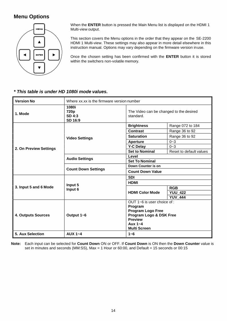
Menu Options
When the ENTER button is pressed the Main Menu list is displayed on the HDMI 1 Multi-view output.
This section covers the Menu options in the order that they appear on the SE-2200
HDMI 1 Multi-view. These settings may also appear in more detail elsewhere in this
instruction manual. Options may vary depending on the firmware version in use.
Once the chosen setting has been confirmed with the ENTER button it is stored
within the switchers non-volatile memory.
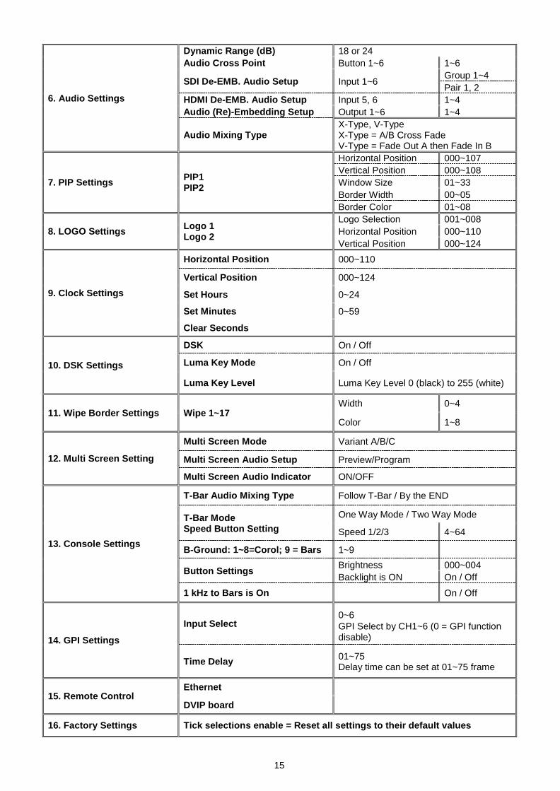
* This table is under HD 1080i mode values.
Version No Where xx.xx is the firmware version number
1. Mode
1080i 720p SD 4:3 SD 16:9
The Video can be changed to the desired standard.
2. On Preview Settings
Video Settings
Brightness Range 072 to 184
Contrast Range 36 to 92
Saturation Range 36 to 92
Aperture 0~3
Y-C Delay 0~3
Set to Nominal Reset to default values
Audio Settings Level
Set To Nominal
Count Down Settings Down Counter is on
Count Down Value
3. Input 5 and 6 Mode
Input 5 Input 6
SDI
HDMI
HDMI Color Mode
RGB
YUU_422
YUV_444
4. Outputs Sources
Output 1~6
OUT 1~6 is user choice of : Program Program Logo Free Program Logo & DSK Free Preview Aux 1~4 Multi Screen
5. Aux Selection AUX 1~4 1~6
Note: Each input can be selected for Count Down ON or OFF. If Count Down is ON then the Down Counter value is set in minutes and seconds (MM:SS), Max = 1 Hour or 60:00, and Default = 15 seconds or 00:15
15
6. Audio Settings
Dynamic Range (dB) 18 or 24
Audio Cross Point Button 1~6 1~6
SDI De-EMB. Audio Setup Input 1~6 Group 1~4
Pair 1, 2
HDMI De-EMB. Audio Setup Input 5, 6 1~4
Audio (Re)-Embedding Setup Output 1~6 1~4
Audio Mixing Type X-Type, V-Type X-Type = A/B Cross Fade V-Type = Fade Out A then Fade In B
7. PIP Settings PIP1 PIP2
Horizontal Position 000~107
Vertical Position 000~108
Window Size 01~33
Border Width 00~05
Border Color 01~08
8. LOGO Settings Logo 1 Logo 2
Logo Selection 001~008
Horizontal Position 000~110
Vertical Position 000~124
9. Clock Settings
Horizontal Position 000~110
Vertical Position 000~124
Set Hours 0~24
Set Minutes 0~59
Clear Seconds
10. DSK Settings
DSK On / Off
Luma Key Mode On / Off
Luma Key Level Luma Key Level 0 (black) to 255 (white)
11. Wipe Border Settings Wipe 1~17 Width 0~4
Color 1~8
12. Multi Screen Setting
Multi Screen Mode Variant A/B/C
Multi Screen Audio Setup Preview/Program
Multi Screen Audio Indicator ON/OFF
13. Console Settings
T-Bar Audio Mixing Type Follow T-Bar / By the END
T-Bar Mode Speed Button Setting
One Way Mode / Two Way Mode
Speed 1/2/3 4~64
B-Ground: 1~8=Corol; 9 = Bars 1~9
Button Settings Brightness 000~004
Backlight is ON On / Off
1 kHz to Bars is On On / Off
14. GPI Settings
Input Select 0~6
GPI Select by CH1~6 (0 = GPI function disable)
Time Delay 01~75 Delay time can be set at 01~75 frame
15. Remote Control Ethernet
DVIP board
16. Factory Settings Tick selections enable = Reset all settings to their default values

16
How to use the CG-200 software with SE-2200
For example:
1. Use HDMI cable to connect the PC to the SE-2200 (CH-6).
2. Enter SE-2200 Main Menu to set Video Standard.
1. Mode
1080i 720p SD 4:3 SD 16:9
The Video can be changed to the desired standard.
3. Enter SE-2200 Main Menu to set Video Input 6 on HDMI.
3. Input 5 and 6 Mode
Input 5 Input 6
SDI
HDMI
HDMI Color Mode
RGB
YUU_422
YUV_444
4. Activate DownStream Key on SE-2200 Control Keyboard. Please see the DSK Function (Page 21) for more details.

17
5. Install the CG-200 software to the PC.
Step1: Please click the icon to install CG-200 Software
Step2: Install the CG software step by step till it’s finished.
Step3: When finished, please double click the icon to execute the software.
6. Click to select Video Mode (the video mode must the same as SE-2200).
Settings Preferences
18
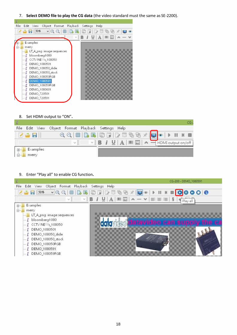
7. Select DEMO file to play the CG data (the video standard must the same as SE-2200).
8. Set HDMI output to “ON”.
9. Enter “Play all” to enable CG function.
19
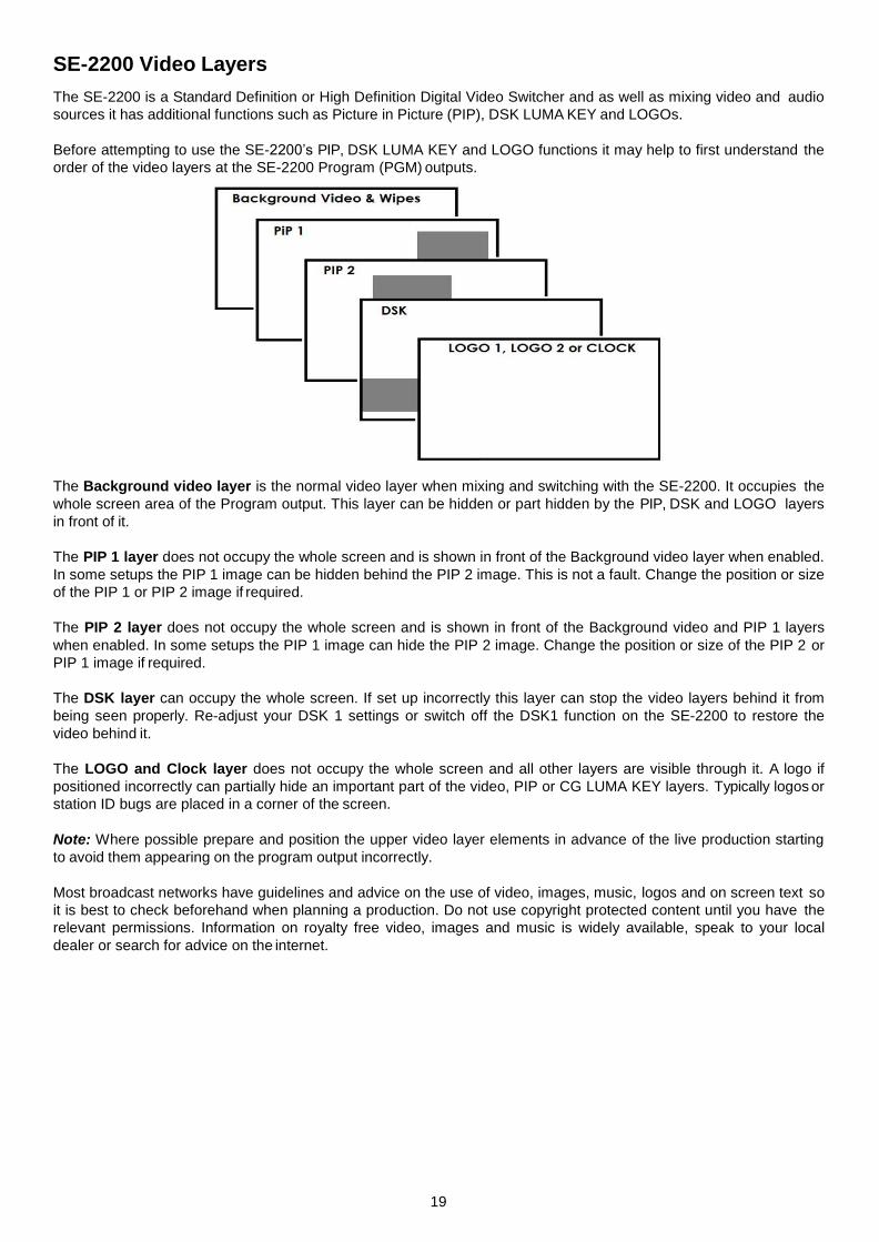
SE-2200 Video Layers
The SE-2200 is a Standard Definition or High Definition Digital Video Switcher and as well as mixing video and audio
sources it has additional functions such as Picture in Picture (PIP), DSK LUMA KEY and LOGOs.
Before attempting to use the SE-2200’s PIP, DSK LUMA KEY and LOGO functions it may help to first understand the
order of the video layers at the SE-2200 Program (PGM) outputs.
The Background video layer is the normal video layer when mixing and switching with the SE-2200. It occupies the
whole screen area of the Program output. This layer can be hidden or part hidden by the PIP, DSK and LOGO layers
in front of it.
The PIP 1 layer does not occupy the whole screen and is shown in front of the Background video layer when enabled.
In some setups the PIP 1 image can be hidden behind the PIP 2 image. This is not a fault. Change the position or size
of the PIP 1 or PIP 2 image if required.
The PIP 2 layer does not occupy the whole screen and is shown in front of the Background video and PIP 1 layers
when enabled. In some setups the PIP 1 image can hide the PIP 2 image. Change the position or size of the PIP 2 or
PIP 1 image if required.
The DSK layer can occupy the whole screen. If set up incorrectly this layer can stop the video layers behind it from
being seen properly. Re-adjust your DSK 1 settings or switch off the DSK1 function on the SE-2200 to restore the
video behind it.
The LOGO and Clock layer does not occupy the whole screen and all other layers are visible through it. A logo if
positioned incorrectly can partially hide an important part of the video, PIP or CG LUMA KEY layers. Typically logos or
station ID bugs are placed in a corner of the screen.
Note: Where possible prepare and position the upper video layer elements in advance of the live production starting
to avoid them appearing on the program output incorrectly.
Most broadcast networks have guidelines and advice on the use of video, images, music, logos and on screen text so
it is best to check beforehand when planning a production. Do not use copyright protected content until you have the
relevant permissions. Information on royalty free video, images and music is widely available, speak to your local
dealer or search for advice on the internet.
20
Picture in Picture Function
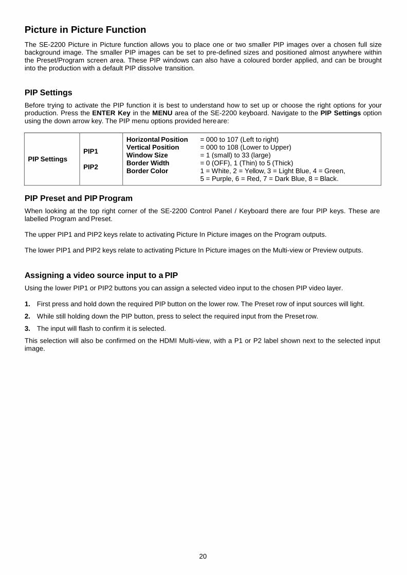
The SE-2200 Picture in Picture function allows you to place one or two smaller PIP images over a chosen full size background image. The smaller PIP images can be set to pre-defined sizes and positioned almost anywhere within the Preset/Program screen area. These PIP windows can also have a coloured border applied, and can be brought into the production with a default PIP dissolve transition.
PIP Settings
Before trying to activate the PIP function it is best to understand how to set up or choose the right options for your production. Press the ENTER Key in the MENU area of the SE-2200 keyboard. Navigate to the PIP Settings option using the down arrow key. The PIP menu options provided here are:
PIP Settings
PIP1
PIP2
Horizontal Position = 000 to 107 (Left to right) Vertical Position = 000 to 108 (Lower to Upper) Window Size = 1 (small) to 33 (large) Border Width = 0 (OFF), 1 (Thin) to 5 (Thick) Border Color 1 = White, 2 = Yellow, 3 = Light Blue, 4 = Green,
5 = Purple, 6 = Red, 7 = Dark Blue, 8 = Black.
PIP Preset and PIP Program
When looking at the top right corner of the SE-2200 Control Panel / Keyboard there are four PIP keys. These are labelled Program and Preset.
The upper PIP1 and PIP2 keys relate to activating Picture In Picture images on the Program outputs.
The lower PIP1 and PIP2 keys relate to activating Picture In Picture images on the Multi-view or Preview outputs.
Assigning a video source input to a PIP
Using the lower PIP1 or PIP2 buttons you can assign a selected video input to the chosen PIP video layer.
1. First press and hold down the required PIP button on the lower row. The Preset row of input sources will light.
2. While still holding down the PIP button, press to select the required input from the Preset row.
3. The input will flash to confirm it is selected.
This selection will also be confirmed on the HDMI Multi-view, with a P1 or P2 label shown next to the selected input image.
21
DSK Function
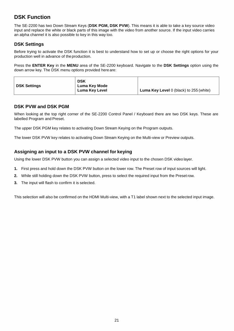
The SE-2200 has two Down Stream Keys (DSK PGM, DSK PVW). This means it is able to take a key source video input and replace the white or black parts of this image with the video from another source. If the input video carries an alpha channel it is also possible to key in this way too.
DSK Settings
Before trying to activate the DSK function it is best to understand how to set up or choose the right options for your
production well in advance of the production.
Press the ENTER Key in the MENU area of the SE-2200 keyboard. Navigate to the DSK Settings option using the down arrow key. The DSK menu options provided here are:
DSK Settings
DSK Luma Key Mode Luma Key Level
Luma Key Level 0 (black) to 255 (white)
DSK PVW and DSK PGM
When looking at the top right corner of the SE-2200 Control Panel / Keyboard there are two DSK keys. These are
labelled Program and Preset.
The upper DSK PGM key relates to activating Down Stream Keying on the Program outputs.
The lower DSK PVW key relates to activating Down Stream Keying on the Multi-view or Preview outputs.
Assigning an input to a DSK PVW channel for keying
Using the lower DSK PVW button you can assign a selected video input to the chosen DSK video layer.
1. First press and hold down the DSK PVW button on the lower row. The Preset row of input sources will light.
2. While still holding down the DSK PVW button, press to select the required input from the Preset row.
3. The input will flash to confirm it is selected.
This selection will also be confirmed on the HDMI Multi-view, with a T1 label shown next to the selected input image.

22
AUDIO Function
Overview
The SE-2200 has a simple, cost effective, audio switcher built in. The SE-2200 has the ability to take audio from
several sources either XLR analogue, SDI and/or HDMI inputs. The audio can be embedded onto the HDMI and SDI
outputs and/or fed to the analogue XLR audio connections.
When using the audio functions of the SE-2200 switcher you may de-embed audio from selected SDI or HDMI inputs and then output this audio from the XLR outputs of the switcher to a separate audio mixer like the Datavideo AM-100 audio mixer.
Once the audio is mixed externally with any microphones or audio sources it can then be fed back into the SE-2200
on the analogue XLR inputs. The SE-2200 can then embed this externally mixed audio on to the Program SDI outputs.

23
AUDIO FOLLOW VIDEO
AUDIO FOLLOW VIDEO function is also known as audio follow video. This means that the audio source will switch
with the corresponding video input, and actually follow the T-bar function. The active audio is de-embedded and sent
to the audio output terminals for processing and/or audio levelling/ and or adding more audio sources. The resulting
audio will return and be connected to the audio inputs for the purpose of (re)-embedding the audio to the SDI output.
The selection of the audio groups determines the SDI channel that the audio will be embedded to exactly.
AUDIO FOLLOW VIDEO function is primarily used in talk show or live news broadcasting. Voices of different guests
are directly collected by the corresponding cameras, thus, when the program director switches between different
guests, the video is switched at the same time with voice of the guest during program broadcasting. This function is
definitely an indispensable function during live broadcasting.
AUDIO FIXED
The AUDIO FIXED method, allows a user to manually select which audio input can be matched to the SDI video input and assigned to the audio output terminals, which is shown in the example below:
The table below illustrates that the sound of video input 1 is used for all individual video inputs.
AUDIO ASSOCIATIONS
INPUT 1 (BUTTON 1) 1
INPUT 2 (BUTTON 2) 1
INPUT 3 (BUTTON 3) 1
INPUT 4 (BUTTON 4) 1
INPUT 5 (BUTTON 5) 1
INPUT 6 (BUTTON 6) 1
The AUDIO FIXED function is primarily used during big (concert) events and (wedding) parties. One camera picks up the audio of the audience and/or ambience of that video input 1, which is assigned to be sent to the audio output. The other cameras are assigned to this same audio of video input 1. When the operator switches between the video sources, the sound of video input 1 remains on all the time.
SE-2200 Assigned Audio Output Channel SE-2200 Audio INPUT Channel

24
Audio Menu Options – De-embedding SDI or HDMI audio
Using the following SE-2200 menu options audio can be selected from the SDI or HDMI video inputs.
SDI De-EMB. Audio Setup Inputs 1 to 6 User choice of Group 1,2,3 or 4 Pair 1 or 2
HDMI De-EMB. Audio Setup Input 5 or 6 User choice of Pair 1,2,3 or 4
As each SDI / HD-SDI source can have up to sixteen channels of audio, and HDMI eight channels, we need to
choose the audio channels with the options above and by the following reference tables.
SDI Inputs Embedded Audio
Group Stereo Pair Channel
Group 1
Stereo pair 1 1
2
Stereo pair 2 3
4
Group 2
Stereo pair 3 5
6
Stereo pair 4 7
8
Group 3
Stereo pair 5 9
10
Stereo pair 6 11
12
Group 4
Stereo pair 7 13
14
Stereo pair 8 15
16
HDMI Inputs Embedded Audio
Stereo Pair Channel
Stereo pair 1 1
2
Stereo pair 2 3
4
Stereo pair 3 5
6
Stereo pair 4 7
8
In some cases there may only be two channels of audio associated with the video: Stereo Pair 1.

25
Working with a fixed or single audio source Example 1:
We have two mono mics (channels 1 & 2) connected to an HD camera. These embedded audio channels are
then output from this camera, HD-SDI, to the SE-2200 switcher. If we want to only hear these two audio
channels regardless of the video channel used then we would set up the switcher in the following way.
Press the ENTER key in the MENU area of the SE-2200 keyboard to display the on screen menu on the AUDIO ASSOCIATION of AUDIO SETTING.
Change the Audio Association settings in the menu system to show a value of 1 for each video input channel. Press
the ENTER key to store the audio values chosen for each video input.
Change the SDI Embedded Audio setting in the switcher’s menu system to show a value of Group 1 and Pair 1. Press
the ENTER key to store the audio values chosen for each video input.
Now exit the menu by pressing any wipe key and look at the AUDIO FIXED button in the wipes area of the keyboard.
Select the AUDIO FIXED status with this button when looking at the status area of the HDMI multi-view. The button
will be backlit red.
Switching between different embedded audio sources Example 2:
We have two mono mics each connected to a different HD camera. The embedded audio is then output from each
camera, HD-SDI, to the SE-2200 switcher. If we want to hear the audio from each camera as the video channels are
switched, audio follows video, and then we would set up in the following way.
Press the ENTER key in the MENU area of the SE-2200 keyboard to display the on screen menu on the AUDIO ASSOCIATION of AUDIO SETTING.
Change the Audio Association settings in the menu system to show a value of 1 for each video input channel that is
associated with audio input 1. Then change to a value of 2 each video input channel that is associated with audio
input 2. Press the ENTER key to store the audio values chosen for each video input.
Change the SDI Embedded Audio setting in the switcher’s menu system to show a value of Group 1 and Pair 1.
Press the ENTER key to store the audio values chosen for each video input.
Now exit the menu by pressing any wipe key and look at the AUDIO FIXED button in the wipes area of the keyboard.
Select the AUDIO FOLLOW VIDEO status with this button when looking at the status area of the HDMI multi-view.
The button will be off. The status area is located just below or near the Preset image on the HDMI multi-view monitor.
When switching between the video sources the audio sources will also change. We can choose how the audio will
change sources, whether it is a clean cut (immediate switch) or some sort of transitioned change (cross fade or fade
out & in). To do this we would need to set up with the following menu options.
Auto Audio Mixing Type
User choice of
X type or V type Tick selection
X type = A/B cross fade V type = Fade out A then fade in B
T-Bar Audio Mixing Type
Tick selection of
Follow auto audio mixing type (use above option) By the end (clean cut or immediate audio switch)

26
How to Re-calibrate the SE-2200 T-Bar
After a firmware update of the switcher it will be necessary to re-calibrate the T-Bar to get it working correctly.
1. Move the T-Bar to its lowest position.
2. Power OFF the SE-2200 switcher.
3. Press and hold down BK button on both the Program and Preset rows of the switcher’s keyboard.
4. Power ON the SE-2200 switcher while still holding down the
buttons in step 3.
5. The switcher will start but the keyboard lights will remain dead except for the T-Bar progress LEDs. When these LEDs flash ON and OFF release the buttons from step 3.
6. Move the T-Bar to its top position and then press the CUT button.
7. Move the T-Bar back to its lowest position and then press the
AUTO TAKE button.
8. To exit the calibration procedure, press the CLOCK button.
9. Ensure the TIMER button is OFF.
10. Test the T-Bar. If necessary change the T-Bar Mode in the OSD MENU options.

27
GPI Connections
The SE-2200 can control external recorder/playback devices like the HDR-60/70 via simple contact closure GPI switch.
The GPI interface is a 3.5mm Jack Socket which is situated on the rear panel of the SE-2200. Contact closure between the Outer and Inner contacts on the jack plug will trigger a user selected event. Power is supplied by the SE- 2200 and is less than 5V DC.
This GPI socket can also be used as a socket to trigger record or playback events with other equipment such as the
Datavideo HDR-70 recorder.
SAFETY FIRST The cabling required needs to be designed specifically to connect the SE-2200 to the chosen record
or playback device as they are not all the same. The cabling required can be made by yourself or a competent
technician. Please speak with your Dealer or local Datavideo office to get further help and advice.
SE-2200 Tally Outputs
The SE-2200 has a D-sub 25 pin female tally output port. These
connections provide bi-colour tally information to a number of other
Datavideo products, such as the ITC-100 eight channel talkback
system and the TLM range of LCD Monitors.
These ports are open collector ports and as such do not provide
power to tally light circuits.
The pin outputs are defined as follows:
Dielectric strength: Max. DC 24V
Current: Max. 50mA
Pin No. Signal name Input/Output Description of signal
1 Program 1 Open collector output Tally output of input video Program 1
2 Program 2 Open collector output Tally output of input video Program 2
3 Program 3 Open collector output Tally output of input video Program 3
4 Program 4 Open collector output Tally output of input video Program 4
5 Program 5 Open collector output Tally output of input video Program 5
6 Program 6 Open collector output Tally output of input video Program 6
13 GND Ground Ground
14 Preview 1 Open collector output Tally output of input video Preview 1
15 Preview 2 Open collector output Tally output of input video Preview 2
16 Preview 3 Open collector output Tally output of input video Preview 3
17 Preview 4 Open collector output Tally output of input video Preview 4
18 Preview 5 Open collector output Tally output of input video Preview 5
19 Preview 6 Open collector output Tally output of input video Preview 6

28
Example SE-2200 Set Up

29
Dimensions
30
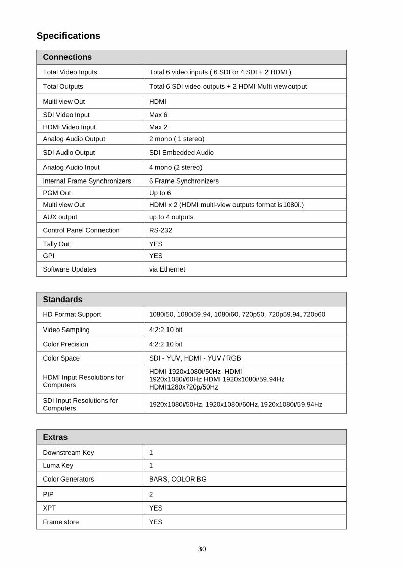
Specifications
Connections
Total Video Inputs Total 6 video inputs ( 6 SDI or 4 SDI + 2 HDMI )
Total Outputs Total 6 SDI video outputs + 2 HDMI Multi view output
Multi view Out HDMI
SDI Video Input Max 6
HDMI Video Input Max 2
Analog Audio Output 2 mono ( 1 stereo)
SDI Audio Output SDI Embedded Audio
Analog Audio Input 4 mono (2 stereo)
Internal Frame Synchronizers 6 Frame Synchronizers
PGM Out Up to 6
Multi view Out HDMI x 2 (HDMI multi-view outputs format is 1080i.)
AUX output up to 4 outputs
Control Panel Connection RS-232
Tally Out YES
GPI YES
Software Updates via Ethernet
Standards
HD Format Support 1080i50, 1080i59.94, 1080i60, 720p50, 720p59.94, 720p60
Video Sampling 4:2:2 10 bit
Color Precision 4:2:2 10 bit
Color Space SDI - YUV, HDMI - YUV / RGB
HDMI Input Resolutions for Computers
HDMI 1920x1080i/50Hz HDMI 1920x1080i/60Hz HDMI 1920x1080i/59.94Hz HDMI 1280x720p/50Hz
SDI Input Resolutions for Computers
1920x1080i/50Hz, 1920x1080i/60Hz, 1920x1080i/59.94Hz
Extras
Downstream Key 1
Luma Key 1
Color Generators BARS, COLOR BG
PIP 2
XPT YES
Frame store YES
31
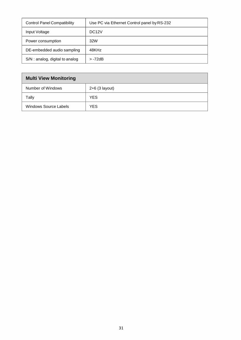
Control Panel Compatibility Use PC via Ethernet Control panel by RS-232
Input Voltage DC12V
Power consumption 32W
DE-embedded audio sampling 48KHz
S/N : analog, digital to analog > -72dB
Multi View Monitoring
Number of Windows 2+6 (3 layout)
Tally YES
Windows Source Labels YES

32
Service and Support