DATA-REQUIREMENTS SPECIFICATION TO SUPPORT BIM-BASED HVAC ... · DATA-REQUIREMENTS SPECIFICATION TO...
9
DATA-REQUIREMENTS SPECIFICATION TO SUPPORT BIM-BASED HVAC- DEFINITIONS IN MODELICA Reinhard Wimmer 1 , Tobias Maile 1 , James O'Donnell 2 , Jun Cao 1 , and Christoph van Treeck 1 1 Institute of Energy Efficient Building, RWTH Aachen University, Germany 2 School of Mechanical and Materials Engineering and Electricity Research Centre, University College Dublin, Ireland {wimmer, maile, cao, treeck}@e3d.rwth-aachen.de, [email protected] ABSTRACT Recent developments in Building Information Model (BIM) capable software are leading to increased interoperability among heterogeneous tools. The results are representing greater levels of data available for all stakeholders involved in the building-industry. The increasing range of data within BIMs enables the reuse of data for downstream applications such as Building Energy Performance Simulation (BEPS). Current BEPS- tools work well in many modeling scenarios, but fail to support innovative and flexible model configurations due to existing tool limitations. Modelica is an object-oriented, equation-based programming language used for detailed dynamic simulation purposes across different industries. The use of Modelica in the building-industry is increasing and it is a promising and flexible tool to provide modeling solutions addressing the upcoming challenges in the building-industry and beyond. This paper illustrates a method of using BIM based information as the primary data source for a flexible simulation application. It includes an implementation for a defined generic use case. INTRODUCTION The building sector produces more than 33% of the greenhouse gases in Germany (Hörner, 2012). Therefore optimizing building performance has a large potential to reduce greenhouse gas emissions (Erdmenger et al., 2007). Current processes of planning, creating and operating buildings have their limitations due to a lack of reliable data exchange. In order to optimize building performance, engineers need dedicated tools to support collaborative engineering work and associated data exchange processes, respectively. BIM is used as a technology to model and manage the digital representation of a building over its entire life-cycle. Following recent developments in this area, the future integration of BIM with BEPS is very promising (van Treeck and Rank, 2007; Eastman, 2011). A BIM-platform may serve as basis for downstream tools but limitations surround the conflict of BIM schemata and the other schemata of these tools. Each tool needs its own specialized data- exchange (Eastman, 2011). The Industrial Foundation Classes (IFC) standard is an open and comprehensive data format used to exchange data within the BIM context. To date IFC implementations primarily focus on building geometry. Recent research projects exists that transform BIM data into BEPS such as the GST-tool project (Geometry Simplification Tool) or the Hesmos-Project. However, they are focusing on geometry and not on HVAC-systems (Liebich et al., 2011; O’Donnell et al., 2013; Rose and Bazjanac, 2013). In addition, updates to the IFC data model require a significant turnaround time for changes and enhancements. The newly developed version of IFC (2x4) has added more parameters, especially for HVAC-system properties. Nevertheless, the additional data do not yet satisfy the requirements for integrated BEPS-tools. Other formats, specialized for exchanging simulation data, like gbXML, focus on geometry and the definition of thermal zones but provide little or no HVAC data. In general, existing formats have a number of limitations when considering the needs of simulation (O'Donnell et al., 2011). Other efforts to increase the availability or relevant data in BIM are in progress. A future standard, ISO 16757, focuses on static calculations for the dimensioning and designing of HVAC components. The standard aims at creating a data repository reflecting manufacturer data of HVAC-components and to enrich the various properties of the components within the IFC-standard. It is anticipated that it will serve as a schema for manufacturers to communicate their data through BIM. However, it is not intended to become a data-repository for different downstream tools such as complex BEPS (Verein Deutscher Ingenieure e. V. VDI, 2011). Today, a small number of BEPS-tools support basic IFC compliance in terms of importing geometry. For example, EnergyPlus is a simulation-engine, which underpins several user interfaces in the BEPS area. EnergyPlus has some inherent limitations such as its rigid data structure. For example, Maile (2010) describes various limitations including the inability of EnergyPlus to model air loops that have two Fifth German-Austrian IBPSA Conference RWTH Aachen University - 99 -
-
Upload
trannguyet -
Category
Documents
-
view
237 -
download
1
Transcript of DATA-REQUIREMENTS SPECIFICATION TO SUPPORT BIM-BASED HVAC ... · DATA-REQUIREMENTS SPECIFICATION TO...
DATA-REQUIREMENTS SPECIFICATION TO SUPPORT BIM-BASED HVAC-DEFINITIONS IN MODELICA
Reinhard Wimmer1, Tobias Maile1, James O'Donnell2, Jun Cao1, and Christoph van Treeck1
1Institute of Energy Efficient Building, RWTH Aachen University, Germany 2School of Mechanical and Materials Engineering and Electricity Research Centre, University
College Dublin, Ireland {wimmer, maile, cao, treeck}@e3d.rwth-aachen.de, [email protected]
ABSTRACT Recent developments in Building Information Model (BIM) capable software are leading to increased interoperability among heterogeneous tools. The results are representing greater levels of data available for all stakeholders involved in the building-industry. The increasing range of data within BIMs enables the reuse of data for downstream applications such as Building Energy Performance Simulation (BEPS). Current BEPS-tools work well in many modeling scenarios, but fail to support innovative and flexible model configurations due to existing tool limitations. Modelica is an object-oriented, equation-based programming language used for detailed dynamic simulation purposes across different industries. The use of Modelica in the building-industry is increasing and it is a promising and flexible tool to provide modeling solutions addressing the upcoming challenges in the building-industry and beyond.
This paper illustrates a method of using BIM based information as the primary data source for a flexible simulation application. It includes an implementation for a defined generic use case.
INTRODUCTION The building sector produces more than 33% of the greenhouse gases in Germany (Hörner, 2012). Therefore optimizing building performance has a large potential to reduce greenhouse gas emissions (Erdmenger et al., 2007). Current processes of planning, creating and operating buildings have their limitations due to a lack of reliable data exchange. In order to optimize building performance, engineers need dedicated tools to support collaborative engineering work and associated data exchange processes, respectively.
BIM is used as a technology to model and manage the digital representation of a building over its entire life-cycle. Following recent developments in this area, the future integration of BIM with BEPS is very promising (van Treeck and Rank, 2007; Eastman, 2011). A BIM-platform may serve as basis for downstream tools but limitations surround the conflict of BIM schemata and the other schemata of
these tools. Each tool needs its own specialized data-exchange (Eastman, 2011). The Industrial Foundation Classes (IFC) standard is an open and comprehensive data format used to exchange data within the BIM context. To date IFC implementations primarily focus on building geometry. Recent research projects exists that transform BIM data into BEPS such as the GST-tool project (Geometry Simplification Tool) or the Hesmos-Project. However, they are focusing on geometry and not on HVAC-systems (Liebich et al., 2011; O’Donnell et al., 2013; Rose and Bazjanac, 2013). In addition, updates to the IFC data model require a significant turnaround time for changes and enhancements. The newly developed version of IFC (2x4) has added more parameters, especially for HVAC-system properties. Nevertheless, the additional data do not yet satisfy the requirements for integrated BEPS-tools. Other formats, specialized for exchanging simulation data, like gbXML, focus on geometry and the definition of thermal zones but provide little or no HVAC data. In general, existing formats have a number of limitations when considering the needs of simulation (O'Donnell et al., 2011).
Other efforts to increase the availability or relevant data in BIM are in progress. A future standard, ISO 16757, focuses on static calculations for the dimensioning and designing of HVAC components. The standard aims at creating a data repository reflecting manufacturer data of HVAC-components and to enrich the various properties of the components within the IFC-standard. It is anticipated that it will serve as a schema for manufacturers to communicate their data through BIM. However, it is not intended to become a data-repository for different downstream tools such as complex BEPS (Verein Deutscher Ingenieure e. V. VDI, 2011).
Today, a small number of BEPS-tools support basic IFC compliance in terms of importing geometry. For example, EnergyPlus is a simulation-engine, which underpins several user interfaces in the BEPS area. EnergyPlus has some inherent limitations such as its rigid data structure. For example, Maile (2010) describes various limitations including the inability of EnergyPlus to model air loops that have two
Fifth German-Austrian IBPSA Conference RWTH Aachen University
- 99 -
alternative return paths (Maile, 2010). Even newly developed user interfaces based on EnergyPlus inherit these limitations. To increase the number of supported model scenarios in practice, flexible tools are required. The object-oriented, equation-based programming language Modelica offers a flexible structure to execute sophisticated BEPS (Wetter et al., 2014). Technologies thereby not mutually exclude each other. For example, co-simulation technologies are available to make submodels available for tools (model-based coupling) (Wetter, 2011).
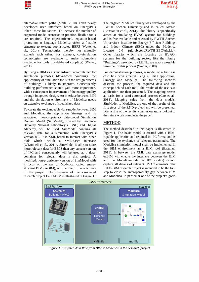
By using a BIM as a standardized data-container for simulation purposes (data-based coupling), the applicability of simulation tools in the design process of buildings is likely to improve. Consequently building performance should gain more importance, with a consequent improvement of the energy quality through integrated design. An interface between BIM and the simulation environment of Modelica needs an extensive exchange of specialized data.
To create the exchangeable data-model between BIM and Modelica, the application Simergy and its associated, non-proprietary data-model Simulation Domain Model (SimModel), created by Lawrence Berkeley National Laboratory (LBNL) and Digital Alchemy, will be used. SimModel contains all relevant data for a simulation with EnergyPlus version 8.0. It is XML-based to interact with other tools which include a XML-based interface (O'Donnell et al., 2011). SimModel is able to store more relevant data for BEPS than any current version of IFC and consequently will be used as a data-container for relevant data in this project. A modified, non-proprietary version of SimModel with a focus on the use of Modelica, called energy efficient BIM (eeBIM), will be one of the outcomes of the project. The overview of the associated research project EnEff-BIM is illustrated in Figure 1.
The targeted Modelica library was developed by the RWTH Aachen University and is called AixLib (Constantin et al., 2014). This library is specifically aimed at simulating HVAC-systems for buildings and is free available and released by RWTH Aachen University's Institute for Energy Efficient Buildings and Indoor Climate (EBC) under the Modelica License 2.0 (github.com/RWTH-EBC/AixLib). Other libraries which are focusing on HVAC-systems for the building sector, like the library “Buildings”, provided by LBNL, are also a possible resource for this process (Wetter, 2009).
For demonstration purposes, a model of a first use case has been created using a CAD application, Simergy and Modelica. The following sections describe the process, the required data and the concept behind each tool. The results of the use case application are then presented. The mapping serves as basis for a semi-automated process (Cao et al., 2014). Mapping rules from the data models, SimModel to Modelica, are one of the results of the first steps of the R&D-project and will be presented. Discussion of the results, conclusion and a lookout to the future work completes the paper.
METHOD The method described in this paper is illustrated in Figure 1. The basic model is created with a BIM-capable application and retained in IFC format and is used for the exchange of relevant parameters. The Modelica simulation model shall be implemented in the BIM environment as a BIM tool (Eastman, 2011). In between the XML data exchange model eeBIM will enable the interface between the BIM and the Modelica-model as IFC (today) cannot capture all details of relevant HVAC elements. The EnEff-BIM research project is intended to be the first step to close the interoperability gap between BIM and Modelica. In particular one of the project’s goals
BIM EnvironmentBIM Platform BIM Tool
CAD/BIMBuilding + HVAC
ModelicaSimulation Model
eeBIMData
Exchange Model
IFC mo-fileXML-file
Figure 1: Targeted data flow from BIM to Modelica in the research project
Fifth German-Austrian IBPSA Conference RWTH Aachen University
- 100 -
is to isolate relevant data from BIM required for a BEPS using Modelica. This process is divided into three distinct steps, based on the tools used in our process.
A use case has been created to analyze the data-flow from a BIM platform to Modelica. While the three data models share basic parameters, they also differ significantly in purpose specific parameters. All the necessary parameters for the creation of the use case in all three applications have been defined. The results of this approach reveal the differences in the three data-models.
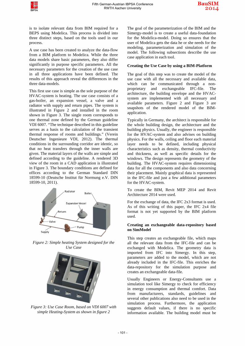
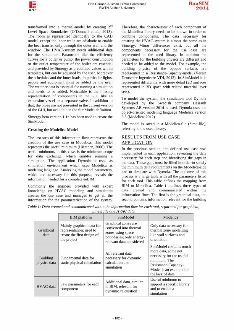
This first use case is simple as the sole purpose of the HVAC-system is heating. The use case consists of a gas-boiler, an expansion vessel, a valve and a radiator with supply and return pipes. The system is illustrated in Figure 2 and installed in the room shown in Figure 3. The single room corresponds to one thermal zone defined by the German guideline VDI 6007. “The technique described in this guideline serves as a basis to the calculation of the transient thermal response of rooms and buildings.” (Verein Deutscher Ingenieure VDI, 2012). The thermal conditions in the surrounding corridor are identic, so that no heat transfers through the inner walls are given. The material layers of the walls are simple and defined according to the guideline. A rendered 3D view of the room in a CAD application is illustrated in Figure 3. The boundary conditions are defined for offices according to the German Standard DIN 18599-10 (Deutsche Institut für Normung e.V. DIN 18599-10, 2011).
Figure 2: Simple heating System designed for the
Use Case
Figure 3: Use Case Room, based on VDI 6007 with
simple Heating-System as shown in figure 2
The goal of the parameterization of the BIM and the Simergy-model is to create a useful data-foundation for the Modelica-model. Doing so ensures that the user of Modelica gets the data he or she needs for the modeling, parameterization and simulation of the model. The following subsections describe the use case application in each tool.
Creating the Use Case by using a BIM-Platform
The goal of this step was to create the model of the use case with all the necessary and available data, which can be communicated through a non-proprietary and exchangeable IFC-file. The architecture, the building envelope and the HVAC-system are implemented with all necessary and available parameters. Figure 2 and Figure 3 are snapshots of the rendered model of the BIM-application.
Typically in Germany, the architect is responsible for the whole building design, the architecture and the building physics. Usually, the engineer is responsible for the HVAC-system and also advises on building physics. For the walls, ceiling and floor each material layer needs to be defined, including physical characteristics such as density, thermal conductivity and thickness, as well as specific details for the windows. The design represents the geometry of the building. The HVAC-system requires dimensioning data for all the components and also data concerning their placement. Mainly graphical data is represented in the IFC-file and just a few additional parameters for the HVAC-system.
To create the BIM, Revit MEP 2014 and Revit Architecture 2014 were used.
For the exchange of data, the IFC 2x3 format is used. As of this writing of this paper, the IFC 2x4 file format is not yet supported by the BIM platform used.
Creating an exchangeable data-repository based on SimModel
This step creates an exchangeable file, which maps all the relevant data from the IFC-file and can be exchanged with Modelica. The geometry data is imported from IFC into Simergy. In this step, parameters are added to the model, which are not already included in the IFC-file. This enriches the data-repository for the simulation purpose and creates an exchangeable data-file.
Usually Engineers or Energy-Consultants use a simulation tool like Simergy to check for efficiency in energy consumption and thermal comfort. Data from manufacturers, standards, guidelines and several other publications also need to be used in the simulation process. Furthermore, the application suggests default values, if there is no specific information available. The building model must be
Fifth German-Austrian IBPSA Conference RWTH Aachen University
- 101 -
transformed into a thermal-model by creating 2nd Level Space Boundaries (O’Donnell et al., 2013). The room is represented identically to the CAD model, except the inner walls are adiabatic to enable the heat transfer only through the outer wall and the window. The HVAC-system needs additional data for the simulation. Parameters like the efficiency curves for a boiler or pump, the power consumption or the outlet temperature of the boiler are essential and provided by Simergy as predefined values within templates, but can be adjusted by the user. Moreover the schedules and the inner loads, in particular lights, people and equipment must be added by the user. The weather data is essential for running a simulation and needs to be added. Noticeable is the missing representation of components in the GUI like an expansion vessel or a separate valve. In addition to that, the pipes are not presented in the current version of the GUI, but available in the SimModel definition.
Simergy beta version 1.1n has been used to create the SimModel.
Creating the Modelica-Model
The last step of this information-flow represents the creation of the use case in Modelica. This model represents the useful minimum (Hietanen, 2006). The useful minimum, in this case, is the minimum scope for data exchange, which enables running a simulation. The application Dymola is used as simulation environment which uses Modelica as modeling language. Analyzing the model parameters, which are necessary for this purpose, reveals the information needed for a complete eeBIM.
Commonly the engineer provided with expert knowledge on HVAC modeling and simulation creates the use case and manages to get all the information for the parameterization of the system.
Therefore, the characteristic of each component of the Modelica library needs to be known in order to combine components. The data necessary for creating the HVAC-system is almost the same as in Simergy. Minor differences exist, but all the components necessary for the use case are represented in the used library. In addition the parameters for the building physics are different and needed to be added to the model. For example, the building physics of the opaque surfaces are represented in a Resistance-Capacity-model (Verein Deutscher Ingenieure VDI, 2012). In SimModel it is represented differently with more detail (2D surfaces represented in 3D space with related material layer sets).
To model the system, the simulation tool Dymola developed by the Swedish company Dassault Systems AB version 2014 is used. Dymola uses the object-oriented modeling language Modelica version 3.3 (Modelica, 2012).
The model is saved in a Modelica-file (*.mo-file), referring to the used library.
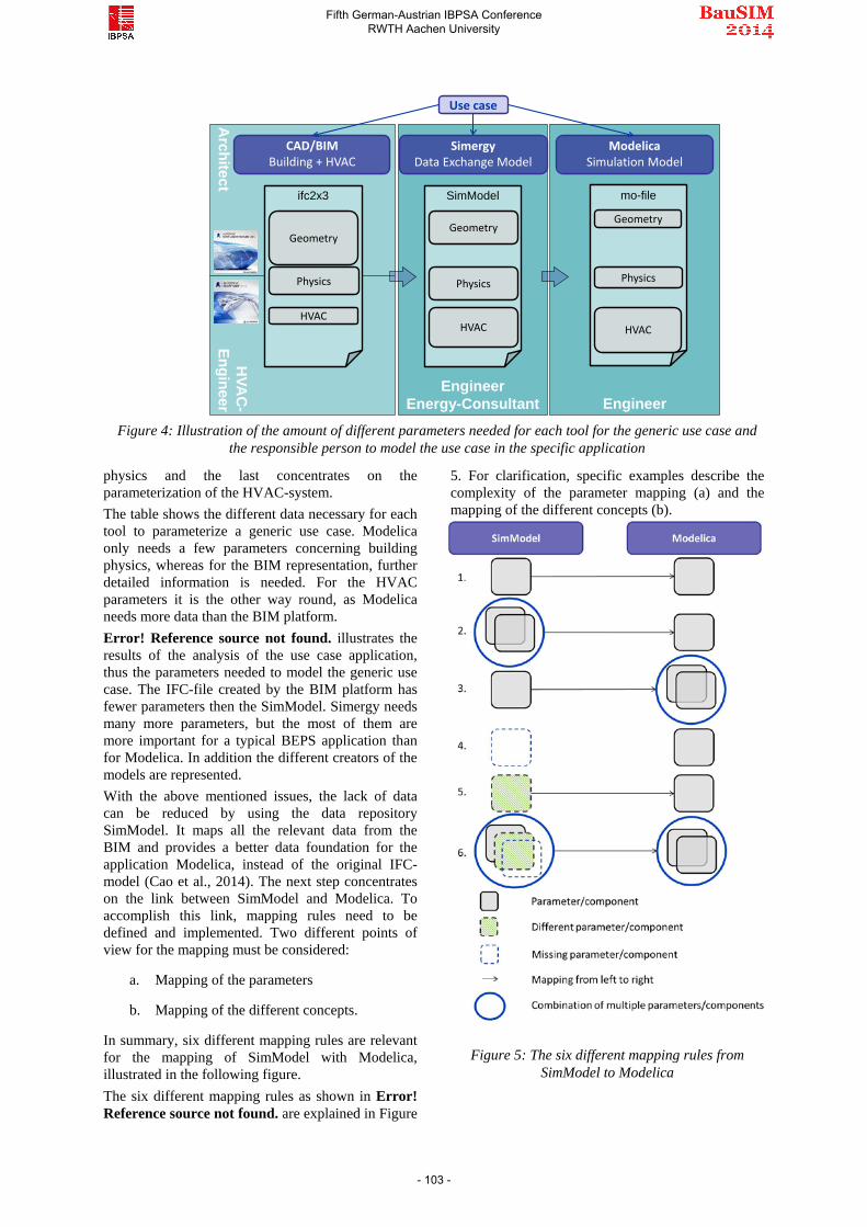
RESULTS FROM USE CASE APPLICATION In the previous section, the defined use case was implemented in each application, revealing the data necessary for each step and identifying the gaps in the data. These gaps must be filled in order to satisfy the minimum data requirements on the Modelica-side and to simulate with Dymola. The outcome of this process is a large table with all the parameters listed for each tool. This table defines the mapping from BIM to Modelica. Table 1 outlines three types of data created and communicated within the information flow. The first is the graphical data, the second contains information relevant for the building
Table 1: Data created and communicated within the information flow for each tool, separated for graphical, physically and HVAC data
BIM platform SimModel Modelica
Graphical data
Mainly graphical data for representation; used to create the first design of the project
Graphical zones are converted into thermal zones using space boundaries; only energy-relevant data considered
Only data necessary for thermal zone modelling like wall surfaces and orientation
Building physics data
Fundamental data for static physical calculation
All relevant data necessary for dynamic calculation and simulation
SimModel contains much more data, some not necessary for the useful minimum. The Resistance-Capacity-Model is an example for the lack of data
HVAC-data Few parameters for each component
Additional data, similar to BIM, relevant for dynamic calculation
Useful minimum to support a specific library and to enable a simulation
Fifth German-Austrian IBPSA Conference RWTH Aachen University
- 102 -
Engineer
HVA
C-
EngineerA
rchitect
EngineerEnergy-Consultant
CAD/BIMBuilding + HVAC
ModelicaSimulation Model
SimModelifc2x3
Use case
mo-file
Geometry
HVAC
Geometry
HVAC
Geometry
HVAC
PhysicsPhysics Physics
SimergyData Exchange Model
Figure 4: Illustration of the amount of different parameters needed for each tool for the generic use case and
the responsible person to model the use case in the specific application
physics and the last concentrates on the parameterization of the HVAC-system. The table shows the different data necessary for each tool to parameterize a generic use case. Modelica only needs a few parameters concerning building physics, whereas for the BIM representation, further detailed information is needed. For the HVAC parameters it is the other way round, as Modelica needs more data than the BIM platform. Error! Reference source not found. illustrates the results of the analysis of the use case application, thus the parameters needed to model the generic use case. The IFC-file created by the BIM platform has fewer parameters then the SimModel. Simergy needs many more parameters, but the most of them are more important for a typical BEPS application than for Modelica. In addition the different creators of the models are represented. With the above mentioned issues, the lack of data can be reduced by using the data repository SimModel. It maps all the relevant data from the BIM and provides a better data foundation for the application Modelica, instead of the original IFC-model (Cao et al., 2014). The next step concentrates on the link between SimModel and Modelica. To accomplish this link, mapping rules need to be defined and implemented. Two different points of view for the mapping must be considered:
a. Mapping of the parameters
b. Mapping of the different concepts.
In summary, six different mapping rules are relevant for the mapping of SimModel with Modelica, illustrated in the following figure. The six different mapping rules as shown in Error! Reference source not found. are explained in Figure
5. For clarification, specific examples describe the complexity of the parameter mapping (a) and the mapping of the different concepts (b).
Figure 5: The six different mapping rules from
SimModel to Modelica
Fifth German-Austrian IBPSA Conference RWTH Aachen University
- 103 -
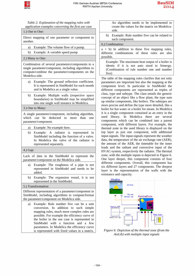
Table 2: Explanation of the mapping rules with application examples concerning the first use case
1.) One to One:
Direct mapping of one parameter or component to another.
a) Example: The volume flow of a pump. b) Example: A variable speed pump
2.) Many to One:
Combination of several parameters/components to a single parameter/component, including algorithms to compute/combine the parameter/components on the Modelica side.
a) Example: The ground reflection coefficient. It is represented in SimModel for each month and in Modelica as a single value.
b) Example: Multiple walls (respective space boundaries) in SimModel may be simplified into one single wall instance in Modelica.
3.) One to Many:
A single parameter/component, including algorithm, which can be deducted to more than one parameter/component.
a) Example: No example here. b) Example: A radiator is represented in
SimModel including the function of a valve. In Modelica the valve of the radiator is represented separately.
4.) Gap:
Lack of data in the SimModel to represent the parameter/component on the Modelica side.
a) Example: The roughness of a pipe is not represented in SimModel and needs to be added.
b) Example: The expansion vessel, it is not represented in the SimModel.
5.) Transformation: Different representation of a parameter/component in SimModel, including algorithms to compute/format the parameter/component on Modelica side.
a) Example: Rule number five can be a unit conversion. In addition to such simple mapping rules, much more complex rules are possible. For example the efficiency curve of the boiler in the use case is represented in SimModel with a function and a few parameters. In Modelica the efficiency curve is represented with fixed values in a matrix.
An algorithm needs to be implemented to create the values for the matrix on Modelica-side.
b) Example: Rule number five can be related to each component.
6.) Combination: a + b) In addition to these five mapping rules, different combinations of these rules are also possible.
Example: The maximum heat output of a boiler is identic if it is not auto sized in Simergy. (Combination of rule number one and number five)
The table of the mapping rules clarifies that not only parameters are important but also the mapping at the component level. In particular in SimModel the different components are represented as triples of class, type and subtype. The class entails the generic concept of an object like a flow plant, the type sum up similar components, like boilers. The subtypes are more precise and define the type more detailed, like a boiler for hot water or a boiler for steam. In Modelica it is a single component contained as an entry in the used library. In Modelica there are several components which can be combined into a parent component, with different layers. For example, the thermal zone in the used library is displayed on the top layer as just one component, with additional input-signals. The input-signals represent the weather data, the temperature of the air exchange rate (AER), the amount of the AER, the timetable for the inner loads and the radiant and convective input of the HVAC-system, respectively the radiator. The thermal zone, with the multiple inputs is depicted in Figure 6. One layer deeper, this component consists of four different components. Overall, this component has six different layers and 27 components. The deepest layer is the representation of the walls with the resistance and capacity.
Figure 6: Depiction of the thermal zone (from the
AixLib) with multiple input signals
Fifth German-Austrian IBPSA Conference RWTH Aachen University
- 104 -

In SimModel, the presentation of the thermal zone is represented differently. The inner loads are represented in SimModel with its schedule typically in hourly format. In Modelica, it is represented in seconds, in an additional *.txt-file. Such differences need to be recognized and to be considered in the creation of the mapping-table and the application of the six mapping rules for the different concepts.
DISCUSSION The interface between BIM and Modelica, through the use of SimModel, is a challenging task. SimModel uses the fixed concept inspired by EnergyPlus and IFC, whereas Modelica does not have any specification to create a component or model. Furthermore, different Modelica practitioners use different libraries and create different components or models. It starts with the designation of a component or a parameter and ends with a completely different concept for the same task. The flexible structure by creating the models in Modelica makes it very powerful and at the same time very complex and challenging for data exchange.
This flexibility is difficult to handle for a standardized interface between BIM and Modelica. In the research project IEA EBC Annex60 (www.iea-annex60.org), specifications for comprehensive Modelica libraries are to be developed. One of the goals of this project is to establish common definitions, which provide a consistent basis for actual four different libraries. The definitions are actually too basic to be really useful for the aimed process. To bridge the gap between BIM and Modelica in the long term it may be possible to develop a non-flexible Modelica library which refers to the standardized IFC parameters from the BIM-side. Another way for an interface could be a
guideline for library developers, which includes definitions for the modeling of the Modelica library. The definitions indicate an interface to eeBIM and therefore to IFC and the BIM. Another approach would be to make the mapping user adjustable, so the user can make changes when there are smaller changes in the library. The adjustable mapping could alos fasilitate more timely updates from the developers to new components and Modelica library changes.
CONCLUSION In this paper, we have presented a process of linking BIM with Modelica. This process is based on a comprehensive data model called eeBIM, which maps all the data provided by the BIM and enriches it with the necessary data for Modelica to run a simulation.
In the method section a simple use case was presented, which has been implemented in the whole BIM-environment as shown in Figure 7. So far we analyzed the needed parameters and the concept in each tool for the first use case. The mapping-table is finished and a first communication of parameters between Simergy, respectively SimModel and Modelica has been implemented. The mapping of the different concepts, so far, shows multiple ways in addressing definitions of parameters, components and concepts. For example, a simple time schedule can be defined in several different ways. The combination of these differences, in applying the mapping rules is a challenging task, especially referring to complex HVAC-components. Figure 7 illustrates with the yellow box the process so far. The results of the use case application explain in detail, that SimModel can be used as a fundamental data-repository. By using SimModel and enhancing it
BIM EnvironmentBIM Platform BIM Tool
CAD/BIMBuilding + HVAC
SimModelData
Exchange Model
ModelicaSimulation Model
Implemen-ting
mappingrules andenhancingdata model
eeBIM
XML-fileIFC mo-file
Figure 7: Actual status of the project EnEff-BIM, enhancing SimModel and implementing the mapping rules, to enable the link between BIM and Modelica with eeBIM
Fifth German-Austrian IBPSA Conference RWTH Aachen University
- 105 -
with the required additional data and implementing the six different mapping rules, the interface to the AixLib will become reality.
The development of the XML-based data model eeBIM opens a completely new field in connecting BIM with Modelica. eeBIM will represent a comprehensive data model to make use of data created in a BIM and enabling an interface between BIM and Modelica. By providing this required tool for optimizing the building performance, the limitations in the processes of planning, creating and operating should decrease. This paper illustrates the first in this undertaking. The process so far is done manually, but will be improved by an automatic process, including the mapping rules for the AixLib (Cao et al., 2014). This work provides a step towards improving the tools for the engineer that can then better optimize the performance of buildings and reduce greenhouse gas emissions.
FUTURE WORK This first step towards linking BIM with Modelica is described in this paper with a first use case. The focus was on HVAC-systems. Further research projects should include the geometry aspect (van Treeck and Rank, 2007) as well in terms of creating an interface to Modelica. The next steps are implementing more and in particular more complex use cases to analyses different aspects of this linking and support the Modelica library AixLib. Other libraries and the recent published IFC 2x4 Standard are in focus for further improvement of this interface. By that, we intend to understand and improve the data-link between BIM and Modelica and implement Modelica as a BIM-Tool in the BIM-environment.
ACKNOWLEDGEMENT The work parts conducted within the German research project EnEff-BIM participating in the IEA EBC Annex 60 (www.iea-annex60.org) are financially supported by the German Federal Ministry for Economics and Energy BMWi (www.BMWi.de) under grant no 03ET1177A.
Other parts (no duplications) of the preliminary research work in Ireland were supported by a Marie Curie FP7 Integration Grant within the 7th European Union Framework Programme.
REFERENCES Cao, J., Maile, T., O'Donnell, J., Wimmer, R., van
Treeck, C., 2014. Model Transformation from SimModel to Modelica for Building Energy Performance Simulation, in: , BauSim 2014.
Constantin, A., Streblow, R., Müller Dirk (Eds.), 2014. The Modelica HouseModels Library: Presentation and Evaluation of a Room Model with the ASHRAE Standard 140.
Deutsche Institut für Normung e.V. DIN 18599-10, 2011. Calculation of the net, final and primary energy demand for heating, cooling, ventilation, domestic hot water and lighting. Berechnung des Nutz-, End- und Primärenergiebedarfs für Heizung, Kühlung, Lüftung, Trinkwarmwasser und Beleuchtung. Beuth, Berlin, 102 pp. ICS 91.120.10; 91.140.01.
Eastman, C.M., 2011. BIM handbook. A guide to building information modeling for owners, managers, designers, engineers, and contractors, second edition, 2nd ed. John Wiley & Sons, Hoboken, N.J, 1 online resource.
Erdmenger, C., Lehmann, H., Müschen, K., Tambke, J. (Eds.), 2007. UBA-Klimaschutzszenario. Klimaschutz in Deutschland: 40%-Senkung der CO2-Emissionen bis 2020 gegenüber 1990. Umweltbundesamt, Dessau, 70 pp.
Hietanen, J., 2006. The useful minimum, Tampere, 4 pp.
Hörner, M., 2012. Nichtwohngebäude im Bestand. Strategien für Energieeffizienz und Klimaschutz, Darmstadt, 9 pp.
Liebich, T., Stuhlmacher, K., Katranuschkov, P., Guruz, R., Nisbet, N., Kaiser, J., Hensel, B., Zellner, R., Laine, T., Geißler, M., 2011. ICT Platform for Holistic Energy Efficiency Simulation and Lifecycle Management of Public Use Facilities - Hesmos Virtual Energy Lab. Deliverable D2.1: BIM Enhancement Specification, 54 pp.
Maile, T., 2010. Comparing Measured and Simulated Building Energy Performance Data. Ph.D. Thesis, Stanford.
Modelica, 2012. Modelica - A Unified Object-Oriented Language for Systems Modeling Version 3.3. Modelica.
O’Donnell, J.T., Maile, T., Rose, C., Mrazović, N., Morrissey, E., Regnier, C., Parrish, K., Bazjanac, V., 2013. Transforming BIM to BEM:. Generation of Building Geometry for the NASA Ames Sustainability Base BIM.
O'Donnell, J., See, R., Rose, C., Maile, T., Bazjanac, V., Haves, V., 2011. SimModel: A domain data model for whole building energy simulation. Building Simulation 2011, 382–389.
Rose, C.M., Bazjanac, V., 2013. An algorithm to generate space boundaries for building energy simulation. Engineering with Computers (4), 1–10.
van Treeck, C., Rank, E., 2007. Dimensional reduction of 3D building models using graph theory and its application in building energy simulation. Engineering with Computers 23 (2), 109–122.
Verein Deutscher Ingenieure e. V. VDI, 2011. VDI 3805-1: Product data exchange in the Building Services - Fundamentals. Beuth Verlag GmbH, Berlin, 196 pp. ICS 35.240.99, 97.120.
Fifth German-Austrian IBPSA Conference RWTH Aachen University
- 106 -
Verein Deutscher Ingenieure VDI, 2012. VDI 6007 - Calculation of transient thermal response of rooms and buildings. Modelling of rooms, 97 pp. ICS 91.120.10, 91.140.10.
Wetter, M. (Ed.), 2009. A Modelica-based Model Library for Building Energy and Control Systems. eScholarship, California, 12 pp.
Wetter, M., 2011. Co-simulation of building energy and control systems with the Building Controls Virtual Test Bed. Journal of Building Performance Simulation 4 (3), 185–203.
Wetter, M., Zuo, W., Nouidui, T.S., Pang, X., 2014. Modelica Buildings library. Journal of Building Performance Simulation 7 (4), 253–270.
Fifth German-Austrian IBPSA Conference RWTH Aachen University
- 107 -