Level of Development Specification - Bradley BIM-Revit ... · Level of Development Specification...
165
4 0 4 0 3 3 5 0 3 0 0 2 0 0 1 0 0 20 14 LEVEL OF DEVELOPMENT SPECIFICATION
Transcript of Level of Development Specification - Bradley BIM-Revit ... · Level of Development Specification...

4040
33
50
300
2
00
100
2014
LEVEL OF
DEVELOPMENT
SPECIFICATION
eloisa
Snapshot

Level of Development Specification
Version: 2014 Issued: Dec. 30, 2014
For Building Information Models
Level of Development Specification Version: 2014
www.bimforum.org/lod
2
Contents Contents ..................................................................................................................................................................................................... 2
Acknowledgements .................................................................................................................................................................................... 6
Level of Development (LOD) Specification Introduction ............................................................................................................................. 8
1 Overview ............................................................................................................................................................................................ 8
2 Background ........................................................................................................................................................................................ 8
3 Levels of Development ....................................................................................................................................................................... 9
3.1 Level of Development vs. Level of Detail .................................................................................................................................. 9
4 LOD Definitions .................................................................................................................................................................................. 9
4.1 Fundamental LOD Definitions ................................................................................................................................................ 10
4.2 Caveats ................................................................................................................................................................................... 11
4.3 Project-Specific Information .................................................................................................................................................... 11
5 Updates of This Document ............................................................................................................................................................... 12
Revision History ....................................................................................................................................................................................... 12
A: SUBSTRUCTURE................................................................................................................................................................................ 13
A10 Foundations .................................................................................................................................................................................. 13
A1010 – Standard Foundations ........................................................................................................................................................ 13
A1010.10 – Wall Foundations (Shallow Foundations) ...................................................................................................................... 14
A1010.30 – Column Foundations (Deep Foundations)..................................................................................................................... 16
A1020 – Special Foundations ........................................................................................................................................................... 18
A1020.80 – Grade Beams ................................................................................................................................................................ 19
A20 Subgrade Enclosures .................................................................................................................................................................... 20
A2010 – Walls for Subgrade Enclosures .......................................................................................................................................... 21
A40 Slabs-on-Grade ............................................................................................................................................................................. 22
A4010 – Standard Slabs-on-Grade .................................................................................................................................................. 22
A4020 – Structural Slabs-on-Grade.................................................................................................................................................. 24
B: SHELL .................................................................................................................................................................................................. 25
B10 Superstructure............................................................................................................................................................................... 25
B1010 – Floor Construction .............................................................................................................................................................. 25
B1020 – Roof Construction .............................................................................................................................................................. 44
B1080 – Stairs .................................................................................................................................................................................. 45
B20 Exterior Vertical Enclosures .......................................................................................................................................................... 49
B2010 – Exterior Walls ..................................................................................................................................................................... 49
B2020 – Exterior Windows ............................................................................................................................................................... 61
B2050 – Exterior Doors and Grilles .................................................................................................................................................. 64
B2070 - Exterior Louvers and Vents ................................................................................................................................................. 67
B2080 - Exterior Wall Appurtenances............................................................................................................................................... 67
B2090 – Exterior Wall Specialties .................................................................................................................................................... 68
B30 Exterior Horizontal Enclosures ...................................................................................................................................................... 68
B3010 – Roofing ............................................................................................................................................................................... 68

Level of Development Specification Version: 2014
www.bimforum.org/lod
3
B3020 – Roof Appurtenances .......................................................................................................................................................... 69
B3040 – Traffic Bearing Horizontal Enclosures ................................................................................................................................ 69
B3060 – Horizontal Openings ........................................................................................................................................................... 70
B3080 – Overhead Exterior Enclosures ........................................................................................................................................... 71
C: INTERIORS ......................................................................................................................................................................................... 72
C10 Interior Construction ...................................................................................................................................................................... 72
C1010 – Interior Partitions ................................................................................................................................................................ 72
C1020 – Interior Windows ................................................................................................................................................................ 82
C1030 – Interior Doors ..................................................................................................................................................................... 83
C1040 – Interior Grilles and Gates ................................................................................................................................................... 85
C1060 – Raised Floor Construction.................................................................................................................................................. 85
C1070 – Suspended Ceiling Construction ........................................................................................................................................ 86
C1090 – Interior Specialties ............................................................................................................................................................. 87
C20 Interior Finishes ............................................................................................................................................................................ 90
C2010 – Wall Finishes ...................................................................................................................................................................... 90
C2020 – Interior Fabrications ........................................................................................................................................................... 91
C2030 – Flooring .............................................................................................................................................................................. 91
C2040 – Stair Finishes ..................................................................................................................................................................... 91
C2050 – Ceiling Finishes .................................................................................................................................................................. 91
D: SERVICES ........................................................................................................................................................................................... 92
D10 Conveying ..................................................................................................................................................................................... 92
D1010 – Vertical Conveying Systems .............................................................................................................................................. 92
D1030 – Horizontal Conveying ......................................................................................................................................................... 93
D1050 – Material Handling ............................................................................................................................................................... 93
D1080 – Operable Access Systems ................................................................................................................................................. 96
D20 Plumbing ....................................................................................................................................................................................... 97
D2010 – Domestic Water Distribution............................................................................................................................................... 97
D2020 – Sanitary Drainage ............................................................................................................................................................ 102
D2030 – Building Support Plumbing Systems ................................................................................................................................ 105
D2050 – General Service Compressed-Air .................................................................................................................................... 110
D2060 – Process Support Plumbing Systems ................................................................................................................................ 110
D30 HVAC .......................................................................................................................................................................................... 113
D3010 – Facility Fuel Systems ....................................................................................................................................................... 113
D3020 – Heating Systems .............................................................................................................................................................. 118
D3030 – Cooling Systems .............................................................................................................................................................. 121
D3050 – Facility HVAC Distribution Systems ................................................................................................................................. 124
D3060 – Ventilation ........................................................................................................................................................................ 127
D3070 – Special Purpose HVAC Systems ..................................................................................................................................... 131
D40 Fire Protection............................................................................................................................................................................. 131
D4010 – Fire Suppression .............................................................................................................................................................. 131
D4030 – Fire Protection Specialties ............................................................................................................................................... 134

Level of Development Specification Version: 2014
www.bimforum.org/lod
4
D50 Electrical ..................................................................................................................................................................................... 135
D5010 – Facility Power Generation ................................................................................................................................................ 135
D5020 – Electrical Service and Distribution .................................................................................................................................... 137
D5030 – General Purpose Electrical Power ................................................................................................................................... 140
D5040 – Lighting ............................................................................................................................................................................ 141
D5080 – Miscellaneous Electrical Systems .................................................................................................................................... 143
D60 Communications ......................................................................................................................................................................... 145
D6010 – Data Communications ...................................................................................................................................................... 145
D6020 – Voice Communications .................................................................................................................................................... 145
D6030 – Audio-Video Communication............................................................................................................................................ 145
D6060 – Distributed Communications and Monitoring ................................................................................................................... 145
D6090 – Communications Supplementary Components ................................................................................................................ 145
D70 Electronic Safety and Security .................................................................................................................................................... 145
D7010 – Access Control and Intrusion Detection ........................................................................................................................... 145
D7030 – Electronic Surveillance ..................................................................................................................................................... 145
D7050 – Detection and Alarm ........................................................................................................................................................ 145
D7070 – Electronic Monitoring and Control .................................................................................................................................... 146
D7090 – Electronic Safety and Security Supplementary Components ........................................................................................... 146
D80 Integrated Automation ................................................................................................................................................................. 146
D8010 – Integrated Automation Facility Controls ........................................................................................................................... 146
E: EQUIPMENT & FURNISHINGS ......................................................................................................................................................... 147
E10 Equipment ................................................................................................................................................................................... 147
E1010 – Vehicle and Pedestrian Equipment .................................................................................................................................. 147
E1030 – Commercial Equipment .................................................................................................................................................... 147
E1040 – Institutional Equipment ..................................................................................................................................................... 149
E1060 – Residential Equipment ..................................................................................................................................................... 149
E1070 – Entertainment and Recreational Equipment ..................................................................................................................... 149
E1090 – Other Equipment .............................................................................................................................................................. 149
E20 Furnishings ................................................................................................................................................................................. 150
E2010 – Fixed Furnishings ............................................................................................................................................................. 150
E2050 – Movable Furnishings ........................................................................................................................................................ 151
F: SPECIAL CONSTRUCTION & DEMOLITION .................................................................................................................................... 152
F10 Special Construction ................................................................................................................................................................... 152
F1010 – Integrated Construction .................................................................................................................................................... 152
F1020 – Special Structures ............................................................................................................................................................ 152
F1030 – Special Function Construction .......................................................................................................................................... 152
F1050 – Special Facility Components ............................................................................................................................................ 152
F1060 – Athletic and Recreational Special Construction ................................................................................................................ 152
F1080 – Special Instrumentation .................................................................................................................................................... 152
F20 Facility Remediation .................................................................................................................................................................... 152
F2010 – Hazardous Materials Remediation ................................................................................................................................... 152

Level of Development Specification Version: 2014
www.bimforum.org/lod
5
F30 Demolition ................................................................................................................................................................................... 152
F3010 – Structure Demolition ......................................................................................................................................................... 152
F3030 – Selective Demolition ......................................................................................................................................................... 152
F3050 – Structure Moving .............................................................................................................................................................. 152
G: BUILDING SITEWORK ...................................................................................................................................................................... 153
G10 Site Preparation .......................................................................................................................................................................... 153
G1010 – Site Clearing .................................................................................................................................................................... 153
G1020 – Site Elements Demolition ................................................................................................................................................. 153
G1030 – Site Element Relocations ................................................................................................................................................. 153
G1050 – Site Remediation ............................................................................................................................................................. 153
G1070 – Site Earthwork ................................................................................................................................................................. 153
G20 Site Improvements ...................................................................................................................................................................... 154
G2010 – Roadways ........................................................................................................................................................................ 154
G2020 – Parking Lots ..................................................................................................................................................................... 154
G2030 – Pedestrian Plazas and Walkways .................................................................................................................................... 155
G2040 – Airfields ............................................................................................................................................................................ 155
G2050 – Athletic, Recreational, and Playfield Areas ...................................................................................................................... 155
G2060 – Site Development ............................................................................................................................................................ 155
G2080 – Landscaping .................................................................................................................................................................... 155
G30 Liquid and Gas Site Utilities ........................................................................................................................................................ 156
G3010 – Water Utilities ................................................................................................................................................................... 156
G3020 – Sanitary Sewerage Utilities .............................................................................................................................................. 156
G3030 – Storm Drainage Utilities ................................................................................................................................................... 156
G3050 – Site Energy Distribution ................................................................................................................................................... 156
G3060 – Site Fuel Distribution ........................................................................................................................................................ 156
G3090 – Liquid and Gas Site Utilities Supplementary Components ............................................................................................... 157
G40 Electrical Site Improvements ...................................................................................................................................................... 157
G4010 – Site Electric Distribution Systems .................................................................................................................................... 158
G4050 – Site Lighting ..................................................................................................................................................................... 159
G50 Site Communications .................................................................................................................................................................. 160
G5010 – Site Communications Systems ........................................................................................................................................ 160
G90 Miscellaneous Site Construction ................................................................................................................................................. 160
G9010 – Tunnels ............................................................................................................................................................................ 160
Graphics Index ....................................................................................................................................................................................... 161
Level of Development Specification Version: 2014
www.bimforum.org/lod
6
Acknowledgements
Many thanks to all the individuals and organizations who reviewed and contributed to this work, and to the following industry association representatives and co-chairs of the major discipline subgroups who made this document possible:
Overall co-chairs
Jan Reinhardt, Adept Project Delivery
Jim Bedrick, FAIA, AEC Process Engineering
Domain-Specific Content
Design Construction
Structures
Will Ikerd, PE, LEED AP Ikerd Consulting
David Merrifield, Steel Fab, Inc.
Exterior Skin
James Vandezande, AIA, HOK
Walt Cichonski, L F Driscoll
Interior Construction
Ron Dellaria, RA, CSI, Astorino
Brian Filkins, Mortenson
Building Services
Murat Karakas, Arup
David Francis, Southland Industries
Aaron Lawson, Gould Electric
Civil Will Ikerd, PE, LEED AP Ikerd Consulting
Dan Russell, LEED AP, Sundt Construction, Inc.
Industry association representatives
Dmitri Alferieff, Associated General Contractors
Michael Bomba, Esq., American Institute of Architects
Overall editing
Marisa Strickler, Associated General Contractors
Graphics Creation & Editing
IKERD Consulting, LLC (IKERD.com)
Level of Development Specification Version: 2014
www.bimforum.org/lod
7
Additional Contributors
In addition, we’d like to thank the many contributors from all sectors of the industry who helped make this specification possible, including:
Andy Jizba, US CAD
Bill Klorman, Klorman Construction & ACI 131 BIM Committee Member (Concrete)
Brenda Ikerd, Ikerd Consulting (Structures, Civil)
Brian Skripac, Astorino, AIA TAPChuck Eastman, Ph.D, Georgia Institute of Technology
David Merrifield, Steel Fab, Inc.
Eloisa Amaya, Ikerd Consulting (Graphics Editing, Structures, and Cover)
Jamie L. Davis, PE. LEED AP, Ryan Biggs | Clark Davis Engineering & Surveying (Masonry)
Joe Cipra, Vulcraft/Verco Group (Structural Steel Open Web Joists and Metal Deck)
John Russo, AIA, President, US Institute of Building Documentation (Laser Scanning & Level Of Accuracy)
Kirk Capristo, Astorino (Cover)
Lee Garduno, Southland Industries (MEP)
Luke Faulkner, LEED AP, AISC (Structural Steel)
Matthew J. Gomez PE, SE, Gerdau (Structural Steel)
Michael Bolduc, PE (MA), Simpson Gumpertz & Heger (Structural)
Michael Gustafason, PE, Autodesk (Structural)
Michael Mulder, Southland Industries (MEP)
Paul J. Hause, PE, Structural Consultants Inc. (Structural)
Peter J. Carrato, Ph.D., PE, SE, Bechtel & ACI 131 BIM Committee Chair (Concrete)
R. Wayne Muir, P.E., Structural Consultants Inc. & SEI-CASE BIM Committee Co-Chair (Structures)
Randall McCullough, Ikerd Consulting (Civil, MEP, Enclosures, and Cover)
Rebecca Stanford, Ikerd Consulting (Structures)
Schaeffer Harris, EIT, Ikerd Consulting (MEP)
Scott Babin, ITW Building Components Group (Wood)
Soheil Seiqali, Klorman Construction (Concrete)
Steven Bumbalough, ITW Building Components Group (Wood)
Nothing contained in this work shall be considered to be the rendering of legal advice for specific cases, and readers are responsible for obtaining such advice from their own legal counsel. This work and any forms herein are intended solely for educational and informational purposes. Level of Development Specification © 2014 by BIMForum. No portions of this work may be reproduced or displayed without the express written permission of the copyright holders. All rights reserved.
Level of Development Specification Version: 2014
www.bimforum.org/lod
8
Level of Development (LOD) Specification Introduction
1 Overview
The Level of Development (LOD) Specification is a reference that enables practitioners in the AEC Industry to specify and articulate
with a high level of clarity the content and reliability of Building Information Models (BIMs) at various stages in the design and construction process. The LOD Specification utilizes the basic LOD definitions developed by the AIA for the AIA G202-2013 Building Information Modeling Protocol Form1 and is organized by CSI Uniformat 20102. It defines and illustrates characteristics of model elements of different building systems at different Levels of Development. This clear articulation allows model authors to define what their models can be relied on for, and allows downstream users to clearly understand the usability and the limitations of models they are receiving.
The intent of this Specification is to help explain the LOD framework and standardize its use so that it becomes more useful as a communication tool. It does not prescribe what Levels of Development are to be reached at what point in a project but leaves the specification of the model progression to the user of this document. To accomplish the document’s intent, its primary objectives are:
To help teams, including owners, to specify BIM deliverables and to get a clear picture of what will be included in a BIM deliverable
To help design managers explain to their teams the information and detail that needs to be provided at various points in the design process
To provide a standard that can be referenced by contracts and BIM execution plans.
It should be noted that this Specification does not replace a project BIM Execution Plan (BIMXP), but rather is intended to be used in conjunction with such a plan, providing a means of defining models for specific information exchanges, milestones in a design work plan, and deliverables for specific functions.
All images are intended to illustrate building conditions in compliance with common building codes. However, the images do not take into account site specific conditions, regional building codes and other important information that may have a material change to specific projects. These illustrations are not making representation for fitness for a particular project nor represent code or design compliance.
2 Background
In 2011 the BIMForum initiated the development of this LOD Specification and formed a working group comprising contributors from both the design and construction sides of the major disciplines. The working group first interpreted the AIA’s basic LOD definitions for each building system, and then compiled examples to illustrate the interpretations. Because BIM is being put to an ever increasing number of uses, the group decided that it was beyond the initial scope to address all of them. Instead, the definitions were developed to address model element geometry, with three of the most common uses in mind – quantity take-off, 3D coordination and 3D control and planning. The group felt that in taking this approach the interpretations would be complete enough to support other uses.
1 AIA Contract Document G202-2013, Building Information Modeling Protocol Form is part of a new series of digital practice documents the AIA published in June 2013. The AIA’s updated digital practice documents consist of AIA E203™–2013, Building Information Modeling and Digital Data Exhibit, AIA G201™–2013, Project Digital Data Protocol Form, and AIA G202™–2013, Project Building Information Modeling Protocol Form. For general information on the documents and downloadable samples see www.aia.org/digitaldocs. For executable versions of the documents see http://www.aia.org/contractdocs. 2 UniFormatTM Numbers and Titles used in this publication are from UniFormatTM, published by CSI and Construction Specifications Canada (CSC), and are used with permission from CSI. For a more in-depth explanation of UniFormatTM and its use in the construction industry visit http://www.csinet.org or contact CSI, 110 South Union Street, Suite 100, Alexandria, VA 22314. (800) 689-2900.

Level of Development Specification Version: 2014
www.bimforum.org/lod
9
3 Levels of Development
The Level of Development (LOD) framework addresses several issues that arise when a BIM is used as a communication or collaboration tool, i.e., when someone other than the author extracts information from it:
During the design process, building systems and components progress from a vague conceptual idea to a precise description. In the past there has been no simple way to designate where a model element is along this path. The author knows, but others often don’t.
It’s easy to misinterpret the precision at which an element is modeled. Hand drawings range from pen strokes on a napkin to hard lines with dimensions called out, and it’s easy to infer the precision of the drawing from its appearance. In a model though, a generic component placed approximately can look exactly the same as a specific component located precisely, so we need something besides appearance to tell the difference.
It is possible to infer information from a BIM that the author doesn’t intend – unstated dimensions can be measured with precision, assembly information often exists before it’s been finalized, etc. In the past, this issue has been sidestepped with all-encompassing disclaimers that basically say, “Since some of the information in the model is unreliable, you may not rely on any of it.” The LOD framework allows model authors to clearly state the reliability of given model elements, so the concept becomes “Since some of the information in the model is unreliable, you may only rely on it for what I specifically say you can.”
In a collaborative environment, where people other than the model author are depending on information from the model in order to move their own work forward, the design work plan takes on high importance – it is necessary for the model users to know when information will be available in order to plan their work. The LOD framework facilitates this.
The LOD Framework addresses these issues by providing an industry-developed standard to describe the state of development of various systems within a BIM. This standard enables consistency in communication and execution by facilitating the detailed definition of BIM milestones and deliverables.
3.1 Level of Development vs. Level of Detail LOD is sometimes interpreted as Level of Detail rather than Level of Development. This Specification uses the concept of Levels of Development. There are important differences.
Level of Detail is essentially how much detail is included in the model element. Level of Development is the degree to which the element’s geometry and attached information has been thought through – the degree to which project team members may rely on the information when using the model. In essence, Level of Detail can be thought of as input to the element, while Level of Development is reliable output.
4 LOD Definitions
In 2008, the AIA developed its first set of Level of Development definitions in AIA Document E202™-2008 Building Information Modeling Protocol. Due to the rapidly evolving nature of the use of BIM, the AIA evaluated the AIA E202–2008, including the LOD definitions. The result is the updated and reconfigured Digital Practice documents, AIA E203™–2013, Building Information Modeling and Digital Data Exhibit, AIA G201™–2013, Project Digital Data Protocol Form, and AIA G202™–2013, Project Building Information Modeling Protocol Form, which are accompanied by a detailed guide document entitled Guide and Instructions to the AIA Digital Practice Documents. The AIA’s updated Digital Practice documents include revised LOD definitions.
To help further the standardization and consistent use of the LOD concept, and to increase its usefulness as a foundation for collaboration, the AIA agreed to allow the BIMForum to utilize its latest LOD definitions in this Specification. The LOD definitions that are used in this Specification are identical to those published in the AIA’s updated Digital Practice Documents, with two exceptions.
First, the working group identified the need for an LOD that would define model elements sufficiently developed to enable coordination between disciplines – e.g. clash detection/avoidance, layout, etc. The requirements for this level are higher than those for 300, but not as high as those for 400, thus it was designated LOD 350. The AIA documents do not include LOD 350, but the associated Guide and Instructions references it.
Second, while LOD 500 is included in the AIA’s LOD definitions, the working group did not feel it was necessary to further define and illustrate LOD 500 in this Specification because it relates to field verification. Accordingly the expanded descriptions and graphic illustrations in this Specification are limited to LOD 100-400.

Level of Development Specification Version: 2014
www.bimforum.org/lod
10
4.1 Fundamental LOD Definitions 3
LOD 100 The Model Element may be graphically represented in the Model with a symbol or other generic representation, but does not satisfy the requirements for LOD 200. Information related to the Model Element (i.e. cost per square foot, tonnage of HVAC, etc.) can be derived from other Model Elements.
LOD 200 The Model Element is graphically represented within the Model as a generic system, object, or assembly with approximate quantities, size, shape, location, and orientation. Non-graphic information may also be attached to the Model Element.
LOD 300 The Model Element is graphically represented within the Model as a specific system, object or assembly in terms of quantity, size, shape, location, and orientation. Non-graphic information may also be attached to the Model Element.
LOD 350 The Model Element is graphically represented within the Model as a specific system, object, or assembly in terms of quantity, size, shape, orientation, and interfaces with other building systems. Non-graphic information may also be attached to the Model Element.
LOD 400 The Model Element is graphically represented within the Model as a specific system, object or assembly in terms of size, shape, location, quantity, and orientation with detailing, fabrication, assembly, and installation information. Non-graphic information may also be attached to the Model Element.
LOD 500 The Model Element is a field verified representation in terms of size, shape, location, quantity, and orientation. Non-graphic information may also be attached to the Model Elements.
Example – light fixture:
100 cost/sf attached to floor slabs
200 light fixture, generic/approximate size/shape/location
300 Design specified 2x4 troffer, specific size/shape/location
350 Actual model, Lightolier DPA2G12LS232, specific size/shape/location
400 As 350, plus special mounting details, as in a decorative soffit
Glossary
The expanded definitions use the following interpretations of these terms:
Specific: The quantity, size, shape, location, and orientation of the element as designed can be measured directly from the
model without referring to non-modeled information such as notes or dimension call-outs.
Actual: The model element includes all the qualities of a specific element and is representative of the manufacturer’s model
to be installed or the construction intent of an assembly.
Order of Precedence
The body of this Specification expands on these Fundamental Definitions as they apply to specific building systems and sub-systems. In the event of any conflict, more specific expansions take precedence over less specific expansions and Fundamental Definitions, e.g. the expanded definitions for C1010 take precedence over those for C10, which in turn take precedence over the Fundamental Definitions.
LOD Definitions as Minimum Requirements
The LODs provide five snapshots of the progression of an element from conceptual to specified –there are many steps in this progression between the defined LODs. The LOD definitions, then, should be considered minimum requirements – i.e. an element has
3 The definitions for LOD 100, 200, 300, 400, and 500 included in this Specification represent the updated language that appears in the AIA’s most recent BIM protocol document, G202–2013, Building Information Modeling Protocol Form. The LOD 100, 200, 300, 400 and 500 definitions are produced by the AIA and have been used by permission. Copyright © 2013. The American Institute of Architects. All rights reserved. LOD 350 was developed by the BIMForum working group. Copyright © 2013. The BIMForum and the American Institute of Architects. All rights reserved.
Level of Development Specification Version: 2014
www.bimforum.org/lod
11
progressed to a given LOD only when all the requirements stated in the definition have been met. It should also be noted that the requirements are cumulative – for a given element each LOD definition includes the requirements of all previous LODs. Thus for an element to qualify for LOD 300 it must meet all the requirements for 200 and 100 as well as those stated in the LOD 300 definition.
Model Element Author
This document does not prescribe who the author of a particular component at a certain LOD should be – the sequence of responsibility for modeling various systems will vary from one project to another. To accommodate this variation this document defers to the concept of Model Element Author (MEA) as defined in the AIA E203-2013: “The Model Element Author is the entity (or individual) responsible
for managing and coordinating the development of a specific Model Element to the LOD required for an identified Project milestone, regardless of who is responsible for providing the content in the Model Element." 4
2D Supplementary Drawings
In current practice models are often supplemented with 2D information such as detail drawings. This Specification does not address this supplementation, but rather deals only with what is actually modeled in 3D and any non-graphic information associated with the modeled elements.
4.2 Caveats There is no strict correspondence between LODs and design phases. Building systems are developed at different rates through
the design process – for example, design of the structural system is usually well ahead of the design of interior construction. At completion of the schematic design phase, for example, the model will include many elements at LOD 200, but will also include many at LOD 100, as well as some at LOD 300, and possibly even LOD 400.
Similarly, there is no such thing as an “LOD ___ model”. As previously stated, project models at any stage of delivery will
invariably contain elements and assemblies at various levels of development. As an example, it is not logical to require an “LOD 200 model” at the completion of the schematic design phase. Instead, the “schematic design model deliverable” may contain modeled elements at various levels of development.
4.3 Project-Specific Information As mentioned in the Overview above, this Specification is intended to be used in conjunction with a project BIMXP. Many information needs will vary from project to project, even for identical elements. This kind of information is therefore not included in the LOD definitions specified here, but rather is left to be addressed in individual BIMXPs. The following are some notable examples.
Size Thresholds
In most projects a determination is made to model certain elements only if they are over a specified size – e.g. conduit less than 1/2” (10 mm) diameter is not modeled. These size thresholds do not consistently correspond to certain LODs, and they vary from project to project. Thus they are not specified in the LOD definitions but rather in the project’s BIMXP, for example through the “Notes” cells in the Model Element Table of the AIA G202-2013.
Clearances
Clearances such as door swings, maintenance access zones, and accessibility requirements can be critical design issues and in many cases are geometrically modeled to reserve the space. The implementation of this type of spatial coordination can be accomplished in various ways; therefore it is neither practical nor useful for this Specification to dictate particular requirements, for example, all door swings to be modeled as quarter-cylinder solids. Implementation of required clearances is to be established with individual BIMXPs.
4 AIA Document E203-2013 Building Information Modeling and Digital Data Exhibit. Copyright © American Institute of Architects 2013. All rights reserved. Definition quoted here by permission.

Level of Development Specification Version: 2014
www.bimforum.org/lod
12
5 Updates of This Document
While this document is intended as a reference that can be cited in agreements such as contracts and BIM execution plans, it is recognized that the use of BIM in design and construction is evolving. To accommodate this evolution this document will be updated periodically in clearly identifiable versions. Initially the target frequency is annually, but that may change in the future. In addition, interim updates may be issued if needed.
Revision History
12/30/14 Level of Development Specification 2014 New changes are noted with a bold bar. Definitions have not been changed except for minor grammatical corrections and
formatting. Images and image notes have been added in blue
italics font.
8/22/13 Level of Development Specification 2013
4/24/13 Initial draft for public review

Level of Development Specification Version: 2014
www.bimforum.org/lod
13
A: SUBSTRUCTURE
A10 Foundations 100 Assumptions for foundations are included in other modeled
elements such as an architectural floor element or volumetric mass that contains layer for assumed structural framing depth.
Or, schematic elements that are not distinguishable by type or material. Assembly depth/thickness and locations still flexible.
200 Element modeling to include:
Approximate size and shape of foundation element
Structural building grids for local project coordinate system are defined in model and coordinated with global civil coordinate system (State Plane Coordinate System, etc).
A1010 – Standard Foundations 100 See A10
200 See A10
300 Elements are modeled to the design-specified size and shape of the foundation.
Element modeling to include:
Overall size and geometry of the foundation element
Sloping surfaces or floor depressions
External dimensions of the members
Required non-graphic information associated with model elements includes:
Concrete strength
Reinforcing strength
Level of Development Specification Version: 2014
www.bimforum.org/lod
14
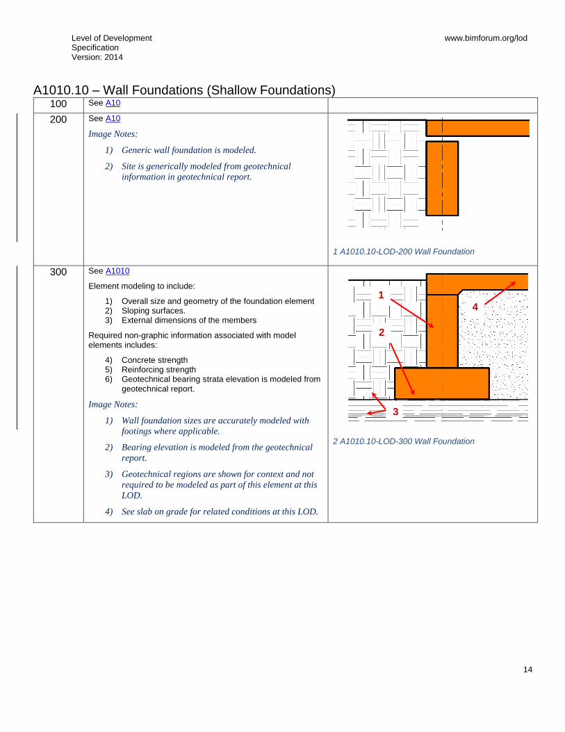
A1010.10 – Wall Foundations (Shallow Foundations) 100 See A10
200
See A10
Image Notes:
1) Generic wall foundation is modeled.
2) Site is generically modeled from geotechnical
information in geotechnical report.
1 A1010.10-LOD-200 Wall Foundation
300
See A1010
Element modeling to include:
1) Overall size and geometry of the foundation element 2) Sloping surfaces. 3) External dimensions of the members
Required non-graphic information associated with model elements includes:
4) Concrete strength 5) Reinforcing strength 6) Geotechnical bearing strata elevation is modeled from
geotechnical report.
Image Notes:
1) Wall foundation sizes are accurately modeled with
footings where applicable.
2) Bearing elevation is modeled from the geotechnical
report.
3) Geotechnical regions are shown for context and not
required to be modeled as part of this element at this
LOD.
4) See slab on grade for related conditions at this LOD.
2 A1010.10-LOD-300 Wall Foundation
4
2
1
3
Level of Development Specification Version: 2014
www.bimforum.org/lod
15
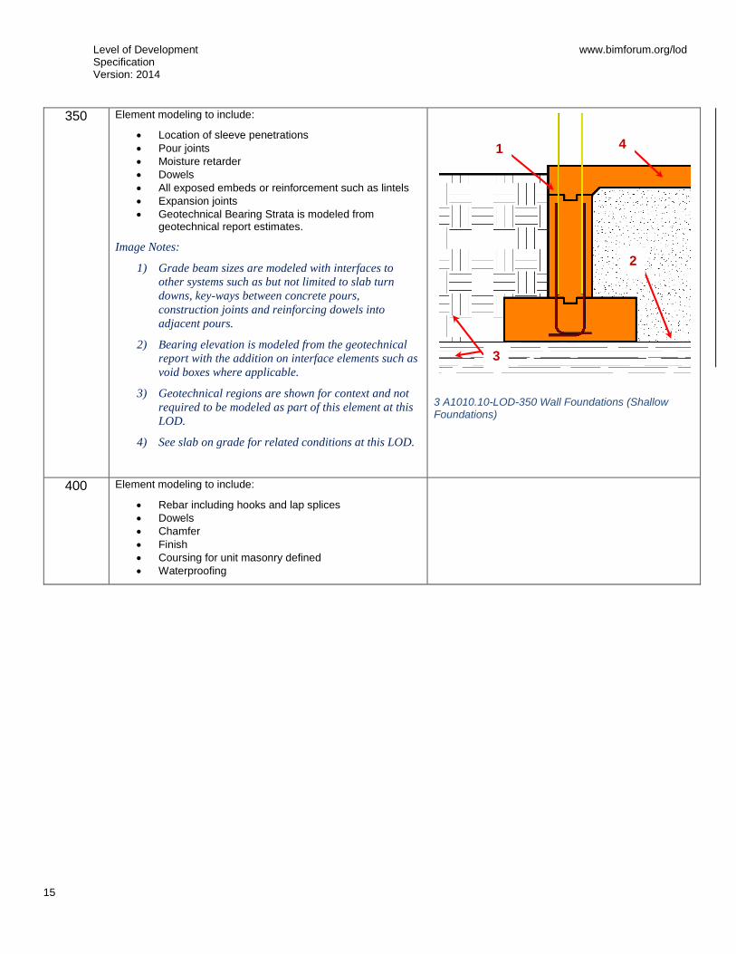
350
Element modeling to include:
Location of sleeve penetrations
Pour joints
Moisture retarder
Dowels
All exposed embeds or reinforcement such as lintels
Expansion joints
Geotechnical Bearing Strata is modeled from geotechnical report estimates.
Image Notes:
1) Grade beam sizes are modeled with interfaces to
other systems such as but not limited to slab turn
downs, key-ways between concrete pours,
construction joints and reinforcing dowels into
adjacent pours.
2) Bearing elevation is modeled from the geotechnical
report with the addition on interface elements such as
void boxes where applicable.
3) Geotechnical regions are shown for context and not
required to be modeled as part of this element at this
LOD.
4) See slab on grade for related conditions at this LOD.
3 A1010.10-LOD-350 Wall Foundations (Shallow Foundations)
400 Element modeling to include:
Rebar including hooks and lap splices
Dowels
Chamfer
Finish
Coursing for unit masonry defined
Waterproofing
4
2
1
3

Level of Development Specification Version: 2014
www.bimforum.org/lod
16
A1010.30 – Column Foundations (Deep Foundations) 100 See A10
200 See A10
300
Element modeling to include:
Assumed bearing depth per geotechnical report with designed penetration geometry modeled.
Top of Pier
Size of Pier
Image Notes:
1) Pier sizes are accurately modeled with top of pier
elevation, estimated depth to bearing and
specified depth of penetration into bearing strata.
2) Geotechnical regions are shown for context and
not required to be modeled as part of this element
at this LOD.
350
Element modeling to include:
Actual Top of Pier (TOP) and expected Bottom of Pier (BOT) modeled per engineers review of site conditions
Foundation dowel locations and anchor rods if applicable.
Image Notes:
1) Pier sizes are accurately modeled with interfaces
to other systems such as but not limited to slab
turn downs, key-ways between concrete pours,
construction joints and reinforcing dowels into
adjacent pours.
2) Geotechnical regions are shown for context and
not required to be modeled as part of this element
at this LOD.
5 A1010.30-LOD-350 Column Foundations
1
1
2
2
4 A1010.30-LOD-300 Column Foundations (Deep Foundations)

Level of Development Specification Version: 2014
www.bimforum.org/lod
17
400
Element modeling to include:
Depth to bearing stratum
Penetration into bearing stratum
Locations of lap splices
Rebar detailing including hooks and lap splices
Dowels
Pier sled or Pier wheel for side clear cover
Pier bolster for bottom clear cover
Image Notes:
1) Pier modeling is developed to include all
fabrication content that is part of the element.
2) Geotechnical regions are shown for context and
not required to be modeled as part of this element
at this LOD.
3) Pier sled, pier wheel, pier bolsters and other
related items are not shown in image for clarity.
6 A1010.30-LOD-400 Column Foundations
1
2

Level of Development Specification Version: 2014
www.bimforum.org/lod
18
A1020 – Special Foundations Includes: Drilling, casing, bell bottom, excavation, dewatering, removal of excavated, materials, reinforcing, and concrete. Drilled Piers, Driven Piles, Mat Foundation.
100 See A10
200 See A10
300 See A1010
350 Element modeling to include:
Location of sleeve penetrations
Pour joints
Moisture retarder
Dowels
All elements needed for cross-trade collaboration are to be modeled
Actual location and shape of structural element
Exposed embeds or reinforcement such as lintels
Penetrations detailed and modeled
Expansion joints
400 Element modeling to include:
Rebar detailing including hooks and lap splices
Dowels
Chamfer
Finish
Coursing for unit masonry defined
Waterproofing

Level of Development Specification Version: 2014
www.bimforum.org/lod
19
A1020.80 – Grade Beams 100 See A10
200
See A10
Image Notes:
1) Generic beam geometry is shown.
2) Geotechnical regions are shown for context and not
required to be modeled as part of this element at this
LOD.
7 A1020.80-LOD-200 Grade Beams
300
See A1010
Image Notes:
1) Grade beam sizes are shown accurately.
2) See slab on grade for related conditions at this LOD.
3) Geotechnical regions are shown for context and not
required to be modeled as part of this element at this
LOD.
8 A1020.80-LOD-300 Grade Beams
2
1
2
3

Level of Development Specification Version: 2014
www.bimforum.org/lod
20
350
Element modeling to include:
1) Water stops 2) Pour joints and sequences required to identify
reinforcing lap spice, scheduling, etc.
Required non-graphic information associated with model elements includes:
3) Post-tension profile and strands if required by the BIMXP.
Image Notes:
1) Grade beam sizes are modeled with interfaces to
other systems such as but not limited to slab turn
downs, key-ways between concrete pours,
construction joints and reinforcing dowels into
adjacent pours.
2) Interface elements such as void boxes are modeled
where applicable.
3) See slab on grade for related conditions at this LOD.
4) Geotechnical regions are shown for context and not
required to be modeled as part of this element at this
LOD.
9 A1020.80-LOD-350 Grade Beams
400 Element modeling to include:
Detailed post-tensioned components
A20 Subgrade Enclosures 100 Solid mass model representing overall building volume; or,
schematic wall elements that are not distinguishable by type or material.
Assembly depth/thickness and locations still flexible.
200 Element modeling to include:
Approximate size and shape of the subgrade enclosure element.
Structural building grids for local project coordinate system are defined in model and coordinated with global civil coordinate system (State Plane Coordinate System, etc).
2
1 3
4

Level of Development Specification Version: 2014
www.bimforum.org/lod
21
A2010 – Walls for Subgrade Enclosures 100 See A20
200 See A20
300 Element modeling to include:
Overall size and geometry of the subgrade element
Sloping surfaces
External dimensions of the element
Material strength
Required non-graphic information associated with model elements includes:
Concrete strength
Reinforcing Strength
Air entrainment
Finishes
350 Element modeling to include:
Chamfers
Sleeve penetrations
Pour joints
Rebar and any embedded elements modeled at congested areas where specified by project BIMXP which is typically with in a set distance from the area of congestion.
Any permanent shoring or forming structures such as void boxes
Interior finish and/or insulation
Expansion joints
Moisture retarder
Exposed embeds or reinforcement such as lintels
Penetrations detailed and modeled
Expansion joints
400 Element modeling to include:
Rebar including hooks and lap splices
Dowels
Chamfer
Finish
Coursing for unit masonry defined
Waterproofing

Level of Development Specification Version: 2014
www.bimforum.org/lod
22
A40 Slabs-on-Grade 100 Assumptions for slabs are included in other modeled elements
such as a volumetric mass or architectural floor element that contains a layer for assumed structural framing depth.
200
Element modeling to include
Generic slab with approximate thickness.
Structural building grids for local project coordinate system are defined in model and coordinated with global civil coordinate system (State Plane Coordinate System, etc).
10 A40-LOD-200 Slabs-on-Grade
A4010 – Standard Slabs-on-Grade 100 See A40
200 See A40
300
Element modeling to include:
Overall size, thickness and geometry of the slab
Slab depressions
Edge turn downs
Material strength
All sloping surfaces included in model element with exception of elements affected by manufacturer selection.
Required non-graphic information associated with model elements includes:
Moisture retarder
Air entrainment
350
Element modeling to include:
Sleeve penetrations
Pour joints
Control joints
Expansion joints
Water stops
Rebar and any embedded elements modeled at congested areas where specified by project BIMXP which is typically with in a set distance from the area of congestion.
Void boxes
Anchor rods
Moisture retarder
Dowels
Post-tension profile and strands if required by the BIMXP.
11 A4010-LOD-300 Standard Slabs-on-Grade
12 A4010-LOD-350 Standard Slabs-on-Grade

Level of Development Specification Version: 2014
www.bimforum.org/lod
23
400 Element modeling to include:
Actual slab dimensions and profiles with fully modeled rebar
Post tensioning components
All joints
Water proofing
Finish

Level of Development Specification Version: 2014
www.bimforum.org/lod
24
A4020 – Structural Slabs-on-Grade 100 See A40
200 See A40
300
Element modeling to include:
Overall size, thickness and geometry of the slab-on-grade
Slab depressions
Edge turn downs
Material strength
All sloping surfaces included in model element with exception of elements affected by manufacturer selection which are not known at this LOD. Such conditions could include floor geometry differences where different specified manufacturers will not be known until the actual system is selected.
Required non-graphic information associated with model elements includes:
Concrete strength
Reinforcing strength
Air entrainment
Moisture Retarder
Slab penetrations
350
Element modeling to include:
Sleeve penetrations
Pour joints
Control joints
Expansion joints
Water Stops
Rebar and any embedded elements modeled at congested areas where specified by project BIMXP which is typically with in a set distance from the area of congestion.
Void boxes
Anchor rods
Moisture retarder
Dowels
Post-tension profile and strands modeled if required by the BIMXP
400 Element modeling to include:
Actual slab dimensions and profiles with fully modeled rebar
Post tensioning components
All joints
Water proofing
Finish
13 A4020-LOD-300 Structural Slabs-on-Grade
14 A4020-LOD-350 Structural Slabs-on-Grade

Level of Development Specification Version: 2014
www.bimforum.org/lod
25
B: SHELL
B10 Superstructure 100 Assumptions for structural framing are included in other modeled
elements such as an architectural floor element that contains a layer for assumed structural framing depth; or, schematic structural elements that are not distinguishable by type or material.
Assembly depth/thickness or component size and locations still flexible.
B1010 – Floor Construction 100 See B10
200 Model elements to include:
Floor with approximate dimensions
Approximate supporting framing members
Structural grids defined
B1010.10 – Floor Structural Frame Description: Structural elements required for support of floor construction within basements and above grade. Includes columns, girders, beams, trusses, joists. Includes cast-in-place concrete, precast concrete, unit masonry, metal framed, and wood framed systems. Includes framed and sleeved openings for services. Includes Floor Construction Supplementary Components as appropriate.
Specific structural systems within this section are listed as follows:
Concrete
Masonry
Steel Framing Columns
Steel Framing Beams
Steel Framing Bracing Rods
Steel Joists
Cold-Formed Metal Framing
Wood Floor Trusses
Level of Development Specification Version: 2014
www.bimforum.org/lod
26
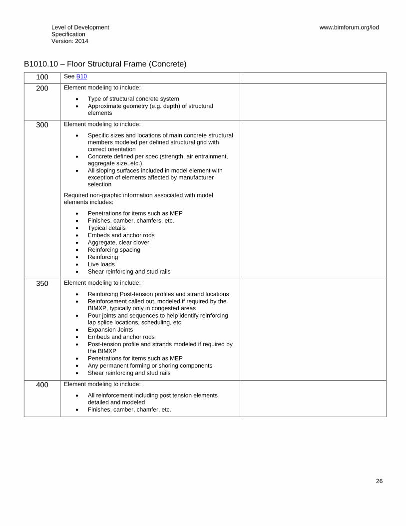
B1010.10 – Floor Structural Frame (Concrete)
100 See B10
200 Element modeling to include:
Type of structural concrete system
Approximate geometry (e.g. depth) of structural elements
300 Element modeling to include:
Specific sizes and locations of main concrete structural members modeled per defined structural grid with correct orientation
Concrete defined per spec (strength, air entrainment, aggregate size, etc.)
All sloping surfaces included in model element with exception of elements affected by manufacturer selection
Required non-graphic information associated with model elements includes:
Penetrations for items such as MEP
Finishes, camber, chamfers, etc.
Typical details
Embeds and anchor rods
Aggregate, clear clover
Reinforcing spacing
Reinforcing
Live loads
Shear reinforcing and stud rails
350 Element modeling to include:
Reinforcing Post-tension profiles and strand locations
Reinforcement called out, modeled if required by the BIMXP, typically only in congested areas
Pour joints and sequences to help identify reinforcing lap splice locations, scheduling, etc.
Expansion Joints
Embeds and anchor rods
Post-tension profile and strands modeled if required by the BIMXP
Penetrations for items such as MEP
Any permanent forming or shoring components
Shear reinforcing and stud rails
400 Element modeling to include:
All reinforcement including post tension elements detailed and modeled
Finishes, camber, chamfer, etc.
Level of Development Specification Version: 2014
www.bimforum.org/lod
27
B1010.10 – Floor Structural Frame (Masonry)
100 See B10
200 Element modeling to include:
Type of structural masonry system
300 Element modeling to include:
Specific sizes of main structural elements modeled per defined structural grid with correct dimensions
Rough openings with reinforcement and lintels called out
Required non-graphic information associated with model elements includes:
Reinforcing
Mortar and grout defined
Reinforcement and steel lintels required at openings
Penetrations for items such as MEP
350 Element modeling to include:
Actual location and shape of structural masonry element
All exposed embeds or reinforcement such as lintels
All penetrations detailed and modeled
Expansion joints
400 Element modeling to include:
Waterproofing
Coursing
Reinforcing
Grout

Level of Development Specification Version: 2014
www.bimforum.org/lod
28
B1010.10 – Floor Structural Frame (Steel Framing Columns)
100 Generic column element, See B10.
200 See B1010
300 Element modeling to include:
Specific sizes of main vertical structural members modeled per defined structural grid with correct orientation
Required non-graphic information associated with model elements includes:
Structural steel materials defined.
Connection details
Finishes, i.e. painted, galvanized, etc.
350 Element modeling to include:
Actual elevations and location of member connections
Large elements of typical connections applied to all structural steel connections such as base plates, gusset plates, anchor rods, etc.
Any miscellaneous steel members with correct orientation
Any steel structure reinforcement such as web stiffeners, sleeve penetrations, etc.
18 B1010.10-LOD-350 Floor Structural Frame (Steel Framing Columns)
15 B1010.10-LOD-100 Floor Structural Frame (Steel Framing Columns)
16 B1010.10-LOD-200 Floor Structural Frame (Steel Framing Columns)
17 B1010.10-LOD-300 Floor Structural Frame (Steel Framing Columns)

Level of Development Specification Version: 2014
www.bimforum.org/lod
29
400 Element modeling to include:
Welds
Coping of members
Cap pates
Washers, nuts, etc.
All assembly elements
19 B1010.10-LOD-400 Floor Structural Frame (Steel Framing Columns)
Level of Development Specification Version: 2014
www.bimforum.org/lod
30
B1010.10 – Floor Structural Frame (Steel Framing Beams)
100 See B10
200 See B1010
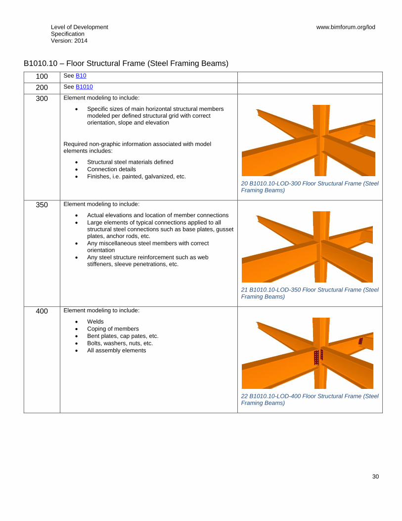
300 Element modeling to include:
Specific sizes of main horizontal structural members modeled per defined structural grid with correct orientation, slope and elevation
Required non-graphic information associated with model elements includes:
Structural steel materials defined
Connection details
Finishes, i.e. painted, galvanized, etc.
20 B1010.10-LOD-300 Floor Structural Frame (Steel Framing Beams)
350 Element modeling to include:
Actual elevations and location of member connections
Large elements of typical connections applied to all structural steel connections such as base plates, gusset plates, anchor rods, etc.
Any miscellaneous steel members with correct orientation
Any steel structure reinforcement such as web stiffeners, sleeve penetrations, etc.
21 B1010.10-LOD-350 Floor Structural Frame (Steel Framing Beams)
400 Element modeling to include:
Welds
Coping of members
Bent plates, cap pates, etc.
Bolts, washers, nuts, etc.
All assembly elements
22 B1010.10-LOD-400 Floor Structural Frame (Steel Framing Beams)
Level of Development Specification Version: 2014
www.bimforum.org/lod
31
B1010.10 – Floor Structural Frame (Steel Framing Miscellaneous Members)
100 See B10
200 See B1010
300 Element modeling to include:
Specific sizes of main horizontal structural members modeled per defined structural grid with correct orientation, slope and elevation
Required non-graphic information associated with model elements includes:
Structural steel materials defined
Connection details
Finishes, i.e. painted, galvanized, etc.
350 Element modeling to include:
Actual elevations and location of member connections
Large elements of typical connections applied to all structural steel connections such as base plates, gusset plates, anchor rods, etc.
Any miscellaneous steel members with correct orientation
Any steel structure reinforcement such as web stiffeners, sleeve penetrations, etc.
400 Element modeling to include:
Welds
Coping of members
Cap pates
Washers, nuts, etc.
All assembly elements
Level of Development Specification Version: 2014
www.bimforum.org/lod
32
B1010.10 – Floor Structural Frame (Steel Framing Bracing Rods)
100 See B10
200 See B1010
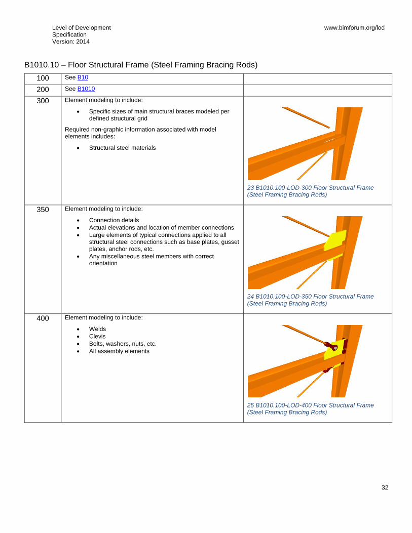
300 Element modeling to include:
Specific sizes of main structural braces modeled per defined structural grid
Required non-graphic information associated with model elements includes:
Structural steel materials
23 B1010.100-LOD-300 Floor Structural Frame (Steel Framing Bracing Rods)
350 Element modeling to include:
Connection details
Actual elevations and location of member connections
Large elements of typical connections applied to all structural steel connections such as base plates, gusset plates, anchor rods, etc.
Any miscellaneous steel members with correct orientation
24 B1010.100-LOD-350 Floor Structural Frame (Steel Framing Bracing Rods)
400 Element modeling to include:
Welds
Clevis
Bolts, washers, nuts, etc.
All assembly elements
25 B1010.100-LOD-400 Floor Structural Frame (Steel Framing Bracing Rods)

Level of Development Specification Version: 2014
www.bimforum.org/lod
33
B1010.10 – Floor Structural Frame (Steel Joists)
100 See B10
200
Element modeling to include:
Approximate depth
300
Element modeling to include:
Joist size, depth, slope, and material
Spacing and end elevations
Joist seat depth
Required non-graphic information associated with model elements includes:
Non-standard joist seat depths and/or sloping joist seat
Member designation, load capacity and deflection criteria
Design loads and location of concentrated loads
Material requirements
27 B1010.10-LOD-300 Floor Structural Frame (Steel Joists)
350
Element modeling to include, information needed for cross trade collaboration such as:
Actual final joist profile locations with accurate panel points
Joist bridging and lateral braces.
Fire protection coating
Any miscellaneous steel pertaining to the joist
Joist seat width
Erection details for installation
Chord and web member section profiles are defined
Joist layout in coordination with metal deck fasteners would be confirmed
Non-standard joist seat depths and\or sloping joist seat
28 B1010.10-LOD-350 Floor Structural Frame (Steel Joists)
26 B1010.10-LOD-200 Floor Structural Frame (Steel Joists)
Level of Development Specification Version: 2014
www.bimforum.org/lod
34
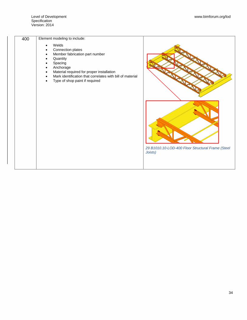
400
Element modeling to include:
Welds
Connection plates
Member fabrication part number
Quantity
Spacing
Anchorage
Material required for proper installation
Mark identification that correlates with bill of material
Type of shop paint if required
29 B1010.10-LOD-400 Floor Structural Frame (Steel Joists)

Level of Development Specification Version: 2014
www.bimforum.org/lod
35
B1010.10 – Floor Structural Frame (Cold-Formed Metal Framing)
100 See B10
200 Element modeling to include:
Rough architectural masses
Approximate member depth
Desired member spacing
300 Element modeling to include:
floor element with design-specified locations and geometries
Required non-graphic information associated with model elements includes:
Member size, depth, and material with sloping geometry
Spacing and end elevations
Design loads
Deflection criteria
350 Element modeling to include:
Members modeled at any interface with wall edges (top, bottom, sides) or opening through wall
Bridging or straps
400 Element modeling to include:
Welds
Connections
Member fabrication part number
Any part required for complete installation

Level of Development Specification Version: 2014
www.bimforum.org/lod
36
B1010.10 – Floor Structural Frame (Masonry Framing)
100 See B10
200
See B10
30 B1010.10-LOD-200 Floor Structural Frame (Masonry Framing)
300
Element modeling to include:
floor element with design-specified locations and geometries
Required non-graphic information associated with model elements includes:
Member size, depth, and material with sloping geometry
Spacing and end elevations
Design loads
Deflection criteria
31 B1010.10-LOD-300 Floor Structural Frame (Masonry Framing)
350
Element modeling to include:
Members modeled at any interface with wall edges (top, bottom, sides) or opening through wall
Any regions that would impact coordination with other systems such as but not limited to:
o Bond Beam & Lintel Regions o Reinforcing & Embed Regions o Jam Regions
32 B1010.10-LOD-350 Floor Structural Frame (Masonry Framing)

Level of Development Specification Version: 2014
www.bimforum.org/lod
37
400
Element modeling to include:
Reinforcing
Connections
Grouting Material
Jams
Bond Beams
Lintels
Member fabrication part number
Any part required for complete installation
33 B1010.10-LOD-400 Floor Structural Frame (Masonry Framing)
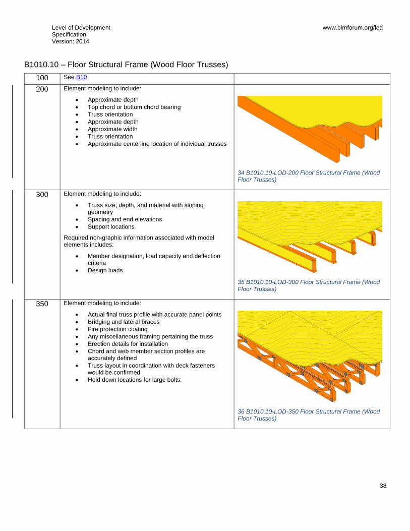
Level of Development Specification Version: 2014
www.bimforum.org/lod
38
B1010.10 – Floor Structural Frame (Wood Floor Trusses)
100 See B10
200
Element modeling to include:
Approximate depth
Top chord or bottom chord bearing
Truss orientation
Approximate depth
Approximate width
Truss orientation
Approximate centerline location of individual trusses
34 B1010.10-LOD-200 Floor Structural Frame (Wood Floor Trusses)
300
Element modeling to include:
Truss size, depth, and material with sloping geometry
Spacing and end elevations
Support locations
Required non-graphic information associated with model elements includes:
Member designation, load capacity and deflection criteria
Design loads
35 B1010.10-LOD-300 Floor Structural Frame (Wood Floor Trusses)
350
Element modeling to include:
Actual final truss profile with accurate panel points
Bridging and lateral braces
Fire protection coating
Any miscellaneous framing pertaining the truss
Erection details for installation
Chord and web member section profiles are accurately defined
Truss layout in coordination with deck fasteners would be confirmed
Hold down locations for large bolts.
36 B1010.10-LOD-350 Floor Structural Frame (Wood Floor Trusses)

Level of Development Specification Version: 2014
www.bimforum.org/lod
39
400
Element modeling to include:
Fasteners
Sealant
Truss plates and connection material
Nails and fasteners
Truss plates.
Deck patterns and joints
37 B1010.10-LOD-400 Floor Structural Frame (Wood Floor Trusses)

Level of Development Specification Version: 2014
www.bimforum.org/lod
40
B1010.20 – Floor Decks, Slabs, and Toppings Description: Structural slab, deck, and sheathing floor construction at intermediate floors of basement construction and above grade. Includes cast-in-place concrete, precast concrete, cementitious decks and toppings, metal decking, wood sheathing, and wood decking. Includes framed and sleeved penetrations for services and housekeeping pads for equipment. Includes Floor Construction Supplementary Components as appropriate.
Specific structural systems within this section are listed as follows:
Wood Floor Deck
Metal Floor Deck
Composite Floor Deck
Concrete
B1010.20 – Floor Decks, Slabs, and Toppings (Wood Floor Deck)
100 See B10
200 See B10
300 Element modeling to include:
Applicable slopes
Expected framing member profiles, spacing, and material
Required non-graphic information associated with model elements includes:
Deck orientation
Deck material layer thicknesses
Diaphragm load and deflection criteria
Deck Material
Deck fasteners
350 Element modeling to include:
Deck edge location
Actual framing member and location per manufacture
All miscellaneous framing including braces, kickers, etc.
Deck openings modeled with support framing around openings
Point load locations
Actual opening locations and sizes defined
400 Element modeling to include:
All framing accessory and fasteners modeled per expected installation
Waterproofing

Level of Development Specification Version: 2014
www.bimforum.org/lod
41
B1010.20 – Floor Decks, Slabs, and Toppings (Metal Floor Deck)
100 See B10
200 See B10
300 Element modeling to include:
Deck thickness
Specific Framing member profiles, spacing, and material
Opening locations are prescriptively defined with notes for additional miscellaneous framing
Point load locations
Required non-graphic information associated with model elements includes:
Diaphragm load and deflection criteria
Deck material
Deck fasteners
Typical weld specifications
350 Element modeling to include:
Deck edge location
Deck splice and end lap locations
Actual deck profile and flute locations per manufacturer
All miscellaneous framing including braces, kickers, etc.
Deck openings modeled with support framing
400 Element modeling to include:
All framing accessory and fasteners modeled per expected installation
Welds
Waterproofing

Level of Development Specification Version: 2014
www.bimforum.org/lod
42
B1010.20 – Floor Decks, Slabs, and Toppings (Composite Floor Deck)
100 See B10
200 See B10
300 Element modeling to include:
Specific deck thickness
Specific Framing member profiles, spacing, material
Opening locations are prescriptively defined with notes for additional miscellaneous framing
Required non-graphic information associated with model elements includes:
Specific deck material
Deck fasteners
Typical weld specifications
Camber
Shear studs
Toppings
350 Element modeling to include:
Deck edge location
Actual deck profile and flute locations per manufacture
Deck splice and end lap locations
Actual framing member and location per manufacture
All miscellaneous framing including deck support, deck closure, shear studs, etc.
Slab openings modeled with support framing around openings
Point load locations
Slab reinforcing modeled if specified in BIMXP
400 Element modeling to include:
All framing accessory and fasteners modeled per expected installation
All slab reinforcing
Welds
Waterproofing

Level of Development Specification Version: 2014
www.bimforum.org/lod
43
B1010.20 – Floor Decks, Slabs, and Toppings (Concrete)
100 See B10
200 Element modeling to include:
Type of structural concrete system
Approximate geometry (e.g. depth) of structural elements
300 Element modeling to include:
Specific sizes and locations of main concrete structural members modeled per defined structural grid with correct orientation
All sloping surfaces included in model element with exception of elements affected by manufacturer selection
Required non-graphic information associated with model elements includes:
Concrete strength,
Reinforcing strength
Air entrainment,
Aggregate size
Typical details
350 Element modeling to include:
Reinforcement called out, modeled if required by the BIMXP, typically only in congested areas
Pour joints and sequences to help identify reinforcing lap splice locations, scheduling, etc.
Expansion Joints
Embeds and anchor rods
Post-tension profile and strands modeled if required by the BIMXP
Penetrations for items such as MEP
Any permanent forming or shoring components
Shear reinforcing and stud rails
Required non-graphic information associated with model elements includes:
Embeds and anchor rods
Aggregate, clear clover
Reinforcing spacing
Reinforcing
Live loads
Shear reinforcing and stud rails
Reinforcing post-tension profiles and strand locations
Penetrations for items such as MEP
Finishes, camber, chamfers, etc.
400 Element modeling to include:
All reinforcement including post tension elements detailed and modeled
Finishes, camber, chamfer, etc.

Level of Development Specification Version: 2014
www.bimforum.org/lod
44
B1020 – Roof Construction [See B1010]
B1020.10 – Roof Structural Frame Description: Structural elements required for support of floor construction within basements and above grade. Includes columns, girders, beams, trusses, joists. Includes cast-in-place concrete, precast concrete, unit masonry, metal framed, and wood framed systems. Includes framed and sleeved openings for services. Includes Floor Construction Supplementary Components as appropriate.
[See B1010.10]
B1020.20 – Roof Decks, Slabs, and Sheathing Includes: Structural roof deck, slab, and sheathing construction. Includes cast-in-place concrete, precast concrete, cementitious decks and toppings, metal decking, wood sheathing, wood decking, timber decking and expansion control. Includes framed and sleeved penetrations for services and housekeeping pads for equipment. Includes Roof Construction Supplementary Components as appropriate.
[See B1010.20]
B1020.30 – Canopy Construction Includes: Structural frame and decks, slabs, and sheathing for canopy construction.
These components are typically modeled as part of other assemblies listed in the tables above. Do not assign this Uniformat classification unless a supplementary component is modeled independently of another assembly.
[See B1010.20]

Level of Development Specification Version: 2014
www.bimforum.org/lod
45
B1080 – Stairs 100 Assumptions for all stair systems (including railings, fire escapes,
walkways, and ladders) are included in other modeled elements such as a spatial or massing element; or, schematic model element that indicates the approximate overall dimensions of the stair layout.
B1080.10 – Stair Construction Includes: Structural framing for exterior and interior stairs including treads, risers, and landings. Includes fire escapes and ladders.
100 See B1080
200
Generic model element with simplified treads and risers.
Nominal overall unit scope shall include:
Nominal plan dimensions (length, width)
Nominal vertical dimensions (levels, landings)
300
Major stair support elements are modeled (stringers).
Treads and risers are modeled to indicate design-specified nosing conditions.
39 B1080.10-LOD-300 Stair Construction
38 B1080.10-LOD-200 Stair Construction

Level of Development Specification Version: 2014
www.bimforum.org/lod
46
350
Secondary stair support elements are modeled (hangers, brackets, etc.).
Required clearance/code zones are modeled.
400
All stair elements are modeled to support fabrication and installation.
41 B1080.10-LOD-400 Stair Construction
40 B1080.10-LOD-350 Stair Construction

Level of Development Specification Version: 2014
www.bimforum.org/lod
47
B1080.50 – Stair Railings 100 See B1080
200
Generic model elements without articulation of material or railing structure such as balusters, posts, or supports.
300
Modeled assemblies by type to include:
Railings
Balusters
Posts
Supports for wall mounted railings
Required non-graphic information associated with model element includes:
Material
350
Secondary railing support elements are modeled including:
Bracing or backing for supports
42 B1080.50-LOD-200 Stair Railings
43 B1080.50-LOD-300 Stair Railings
44 B1080.50-LOD-350 Stair Railings

Level of Development Specification Version: 2014
www.bimforum.org/lod
48
400
[See Fundamental LOD Definitions]
B1080.60 – Fire Escapes [See B1080.10 and B1080.50]
B1080.70 – Metal Walkways [See B1080.10 and B1080.50]
B1080.80 – Ladders [See B1080.10 and B1080.50]
45 B1080.50-LOD-400 Stair Railings

Level of Development Specification Version: 2014
www.bimforum.org/lod
49
B20 Exterior Vertical Enclosures 100 Solid mass model representing overall building volume; or,
schematic wall elements that are not distinguishable by type or material.
Assembly depth/thickness and locations still flexible.
B2010 – Exterior Walls Solid wall construction that is composite in nature; in other words, multiple layers of materials to form an overall assembly.
100 See B20
200 Generic wall objects separated by type of material (e.g. brick wall vs. terracotta).
Approximate overall wall thickness represented by a single assembly.
Layouts and locations still flexible.
46 B2010-LOD-200 Exterior Walls
300 Composite model assembly with specific overall thickness that accounts for veneer, structure, insulation, air space, and interior skin specified for the wall system. (Refer to LOD350 and LOD400 for individually modeled elements)
Penetrations are modeled to nominal dimensions for major wall openings such as windows, doors, and large mechanical elements.
Required non-graphic information associated with model elements includes:
Wall type
Materials
47 B2010-LOD-300 Exterior Walls
350 A composite wall assembly may be considered for LOD350 only if hosted objects such as windows and doors are provided at a minimum of LOD350.
Main structural members such as headers and jambs at openings are modeled within the composite assembly.
48 B2010-LOD-350 Exterior Walls

Level of Development Specification Version: 2014
www.bimforum.org/lod
50
B2010 – Exterior Wall (Masonry) 100 See B10
200
See B2010
49 B2010.04-LOD-200 Exterior Wall (Masonry)
300
Element modeling to include:
Element with design-specified locations and geometries
Required non-graphic information associated with model elements includes:
Member size, depth, and material with sloping geometry
Spacing and end elevations
Design loads
Deflection criteria
50 B2010.04-LOD-300 Exterior Wall (Masonry)
350
Element modeling to include:
Members modeled at any interface with wall edges (top, bottom, sides) or opening through wall
Any regions that would impact coordination with other systems such as but not limited to:
o Bond Beam & Lintel Regions o Reinforcing & Embed Regions o Jam Regions
51 B2010.04-LOD-350 Exterior Wall (Masonry)

Level of Development Specification Version: 2014
www.bimforum.org/lod
51
400
Element modeling to include:
Reinforcing
Connections
Grouting Material
Jams
Bond Beams
Lintels
Member fabrication part number
Any part required for complete installation
52 B2010.04-LOD-400 Exterior Wall (Masonry)

Level of Development Specification Version: 2014
www.bimforum.org/lod
52
B2010 – Exterior Wall (Cold-Form Metal Framing) 100 See B20
200
See B2010
300
See B2010
53 B2010.05-LOD-200 Exterior Wall (Cold-Form Metal Framing)
54 B2010.05-LOD-300 Exterior Wall (Cold-Form Metal Framing)

Level of Development Specification Version: 2014
www.bimforum.org/lod
53
350
Cold formed metal framing is developed with sufficient elements to support detailed interface coordination with other systems such as MEP.
Image notes:
1) Elements in red are critical wall support elements
that cannot be easily cut for coordination of MEP
opening through the walls.
2) Diagonal bracing (kickers) that may be in the
above ceiling space are modeled for coordination
with other building content such as MEP passing
along the wall in the above ceiling spaces.
3) Infill cold formed metal framing modeling (Orange)
may be omitted at this LOD if stated in the BXP.
4) Cladding and sheathing are not shown for clarity in
this image.
2
1
3
55 B2010.05-LOD-350 Exterior Wall (Cold-Form Metal Framing)

Level of Development Specification Version: 2014
www.bimforum.org/lod
54
400
Cold formed metal framing is developed with sufficient elements that support the fabrication of the CFMF system.
Image notes:
1) Connection content is development in the wall
elements. This includes but is not limited to
fasteners, clips, and other related hardware.
2) Cladding and sheathing are not shown for clarity in
this image.
1
56 B2010.05-LOD-400 Exterior Wall (Cold-Form Metal Framing)
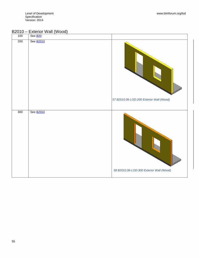
Level of Development Specification Version: 2014
www.bimforum.org/lod
55
B2010 – Exterior Wall (Wood) 100 See B20
200
See B2010
300
See B2010
57 B2010.06-LOD-200 Exterior Wall (Wood)
58 B2010.06-LOD-300 Exterior Wall (Wood)

Level of Development Specification Version: 2014
www.bimforum.org/lod
56
350
Wood framing is developed with sufficient elements to support detailed interface coordination with other systems such as MEP.
Image notes:
1) Elements in red are critical wall support elements
that cannot be easily cut for coordination of MEP
opening through the walls.
2) Infill wood framing modeling may be omitted at this
LOD if stated in the BXP.
3) Cladding and sheathing are not shown for clarity in
this image.
400
Wood framing is developed with sufficient elements that support the fabrication of the wood framing system.
Image notes:
1) Connection content is development in the wall
elements. This includes but is not limited to
fasteners, anchor rods, and other related hardware.
2) Cladding and sheathing are not shown for clarity in
this image.
60 B2010.06-LOD-400 Exterior Wall (Wood)
2
1
1
59 B2010.06-LOD-350 Exterior Wall (Wood)
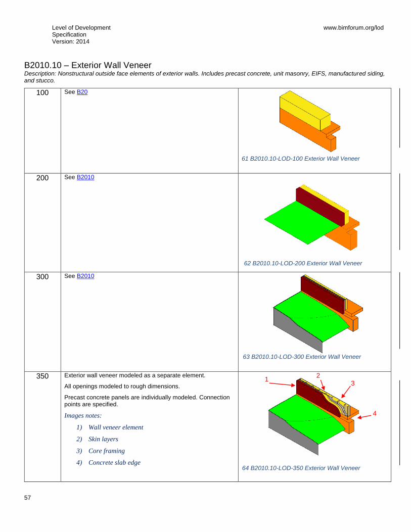
Level of Development Specification Version: 2014
www.bimforum.org/lod
57
B2010.10 – Exterior Wall Veneer Description: Nonstructural outside face elements of exterior walls. Includes precast concrete, unit masonry, EIFS, manufactured siding, and stucco.
100
See B20
200
See B2010
300
See B2010
350
Exterior wall veneer modeled as a separate element.
All openings modeled to rough dimensions.
Precast concrete panels are individually modeled. Connection points are specified.
Images notes:
1) Wall veneer element
2) Skin layers
3) Core framing
4) Concrete slab edge
1 2
3
4
61 B2010.10-LOD-100 Exterior Wall Veneer
62 B2010.10-LOD-200 Exterior Wall Veneer
63 B2010.10-LOD-300 Exterior Wall Veneer
64 B2010.10-LOD-350 Exterior Wall Veneer

Level of Development Specification Version: 2014
www.bimforum.org/lod
58
400
Element modeling includes:
Image notes:
1) Individual masonry units
2) Skin layers including
3) Moisture barrier, sheathing, and insulation
4) Core framing
5) Bolt
6) Concrete slab edge
7) Weep holes
1 2
3
4
5
6
65 B2010.10-LOD-400 Exterior Wall Veneer
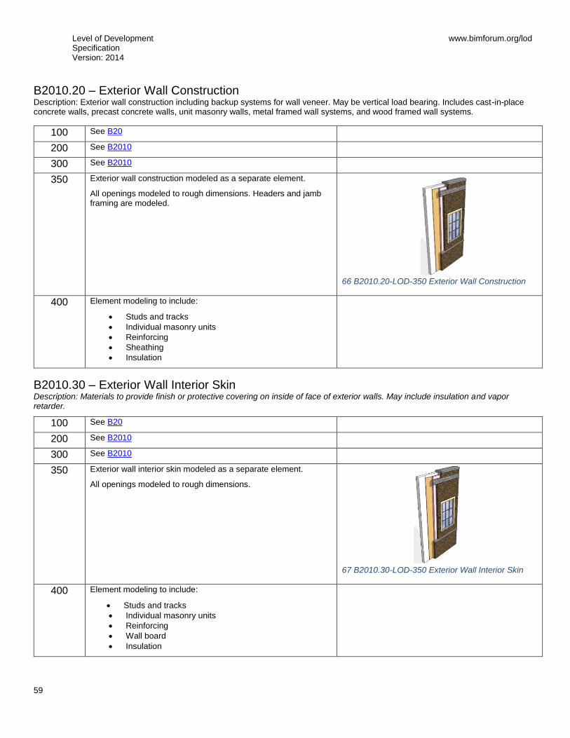
Level of Development Specification Version: 2014
www.bimforum.org/lod
59
B2010.20 – Exterior Wall Construction Description: Exterior wall construction including backup systems for wall veneer. May be vertical load bearing. Includes cast-in-place concrete walls, precast concrete walls, unit masonry walls, metal framed wall systems, and wood framed wall systems.
100 See B20
200 See B2010
300 See B2010
350
Exterior wall construction modeled as a separate element.
All openings modeled to rough dimensions. Headers and jamb framing are modeled.
66 B2010.20-LOD-350 Exterior Wall Construction
400 Element modeling to include:
Studs and tracks
Individual masonry units
Reinforcing
Sheathing
Insulation
B2010.30 – Exterior Wall Interior Skin Description: Materials to provide finish or protective covering on inside of face of exterior walls. May include insulation and vapor retarder.
100 See B20
200 See B2010
300 See B2010
350
Exterior wall interior skin modeled as a separate element.
All openings modeled to rough dimensions.
67 B2010.30-LOD-350 Exterior Wall Interior Skin
400 Element modeling to include:
Studs and tracks
Individual masonry units
Reinforcing
Wall board
Insulation

Level of Development Specification Version: 2014
www.bimforum.org/lod
60
B2010.50 – Parapets Exterior wall construction above plane of roof.
[See B2010, B2010.10, B2010.20, and B2010.30]
B2010.60 – Equipment Screens Exterior wall construction to screen equipment from public view.
[See B2010, B2010.10, B2010.20, and B2010.30]

Level of Development Specification Version: 2014
www.bimforum.org/lod
61
B2020 – Exterior Windows 100 See B20
200
Windows approximate in terms of location, size, count and type. Units are modeled as a simple, monolithic component; or represented with simple frame and glazing.
Nominal unit size is provided.
B2020.10 – Exterior Operating Windows 100 See B20
200 See B2020
300
Units are modeled based on specified location and nominal size. Outer geometry of window frame elements and glazing modeled to within 1/8” [3 mm] precision.
Operation is indicated.
Required non-graphic information associated with model elements includes:
Aesthetic characteristics (finishes, glass types)
Performance characteristics (i.e. U-value, wind loading, blast resistance, structural, air, thermal, water, sound)
Functionality of the window (fixed, casement, double/single hung, awning/project out, pivot, sliding)
350 Rough opening dimensions
Attachment method of window to structure
Embed geometry
400 Frame profiles
Glazing sub-components (gaskets)
Attachment components
B2020.20 – Exterior Fixed Windows [See B2020.10]

Level of Development Specification Version: 2014
www.bimforum.org/lod
62
B2020.30 – Exterior Window Wall 100 See B20
200
Generic wall objects representing major types of proposed window wall assemblies.
Overall window wall assembly depth represented by a single model object.
Layouts and locations still flexible.
68 B2020.30-LOD-200 Exterior Window Wall
300
Specified location and orientation of face of glass.
Nominal face dimensions and thickness of glazing.
Structural support systems of wall to be modeled.
Spacing, location, size and orientation of mullions.
Operable components defined (windows, louvers and doors) and included in model.
69 B2020.30-LOD-300 Exterior Window Wall

Level of Development Specification Version: 2014
www.bimforum.org/lod
63
350
Mullion shapes and geometry defined.
Actual anchorage layouts and types defined.
Actual panel dimensions (including seating).
70 B2020.30-LOD-350 Exterior Window Wall
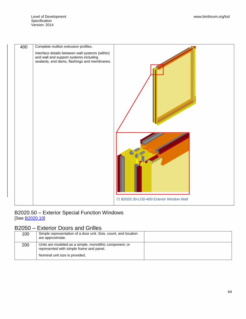
Level of Development Specification Version: 2014
www.bimforum.org/lod
64
400
Complete mullion extrusion profiles.
Interface details between wall systems (within) and wall and support systems including sealants, end dams, flashings and membranes.
71 B2020.30-LOD-400 Exterior Window Wall
B2020.50 – Exterior Special Function Windows [See B2020.10]
B2050 – Exterior Doors and Grilles 100 Simple representation of a door unit. Size, count, and location
are approximate.
200 Units are modeled as a simple, monolithic component; or represented with simple frame and panel.
Nominal unit size is provided.

Level of Development Specification Version: 2014
www.bimforum.org/lod
65
B2050.10 – Exterior Entrance Doors Exterior personnel door assemblies at main entrances. Includes automatic, revolving, balanced, and other special operating entrance doors, and sliding storefront wall systems.
100 See B20
200 See B2050
300
Entrance door assemblies modeled by type to include the following:
Specific door panels and frames (if applicable).
Hardware set functionality and types are specified in non-graphic information.
Operation is specified .Spatial requirements for operation are modeled.
350 Rough opening is modeled (if applicable).
Major framing elements are modeled at jambs and head.
Operation or mechanism enclosures are modeled.
400 Actual frame/mullion extrusions.
Actual panel size dimensions.
All connections and interfaces modeled including brackets, supports, sealants, and thresholds.
B2050.20 – Exterior Utility Doors Exterior personnel door assemblies other than at main entrances.
100 See B20
200 See B2050
300
Entrance door assemblies modeled by type to include the following:
Specific door panels and frames (if applicable).
Hardware set functionality and types are specified in non-graphic information.
Operation is specified graphicly and with non-graphic information.
Spatial requirements for operation are provided.
350 Rough opening is modeled
Major framing elements are modeled at jambs and head
400 All connections and interfaces modeled including brackets, supports, sealants, and thresholds.

Level of Development Specification Version: 2014
www.bimforum.org/lod
66
B2050.30 – Exterior Oversize Doors Large exterior door assemblies to allow for passage of large objects involving various operating methods.
100 See B20
200 See B2050
300
Oversize door assemblies modeled by type to include the following:
Door panels with nominal dimensions.
Frames with nominal dimensions.
Hardware set functionality and types included in non-graphic information.
Clearance zones are modeled for operation of overhead doors.
Enclosures and motor housings are modeled with overall nominal dimensions.
350 Rough opening is modeled (if applicable).
Major framing elements in wall are modeled at jambs and head.
Other major structural support elements are modeled such as support posts and beams.
400 All connections and interfaces modeled including brackets, supports, sealants, and thresholds.
B2050.40 – Exterior Special Function Doors [See B2050.20 or B2050.30]
B2050.60 – Exterior Grilles Exterior devices of open construction to provide moveable barrier to provide access through wall or other divider.
100 See B20
200 See B2050
300 Grille assemblies modeled by type to include the following:
Nominal size of unit.
Required openness provided as non-graphic information.
Operation is specified.
350 Rough opening is modeled (if applicable).
Major framing elements are modeled at jambs and head.
400 All connections and interfaces modeled including brackets, supports, sealants, and thresholds.
B2050.70 – Exterior Gates Exterior devices of solid or open construction to provide moveable barrier to provide access through wall or other divider.
[See B2050.60]

Level of Development Specification Version: 2014
www.bimforum.org/lod
67
B2050.90 – Exterior Door Supplementary Components Includes frames, hardware, glazing and louvers that are part of door to be included with exterior door elements above as appropriate.
These components are typically modeled as part of other assemblies listed in the tables above. Do not assign this Uniformat classification unless a supplementary component is modeled independently of another assembly.
B2070 - Exterior Louvers and Vents 100 See B20
200
Generic model element that is indicative of approximate area and location of intended louver/vent.
B2070.10 – Exterior Louvers 100 See B20
200 See B2070
300 Louver assembly modeled by type, indicative of area and location of intended louver/vent.
Includes accurate frame (boundary dimensions) and blades.
Opening for louver is cut from host wall
Performance level defined in non-graphic information associated with model elements (e.g. storm proof or not, free air)
350 Rough opening is modeled (if applicable)
Major framing elements are modeled at connection points.
Connection points are modeled.
400 All connections and interfaces modeled including brackets, supports, and sealants.
B2070.50 – Exterior Vents [See B2070.10]
B2080 - Exterior Wall Appurtenances [See B2050]
B2080.10 – Exterior Fixed Grilles and Screens Exterior enclosures, grilles and screens of wood, metal, plastic, and other materials for a variety of purposes including screening of equipment.
[See B2050.60]
B2080.30 – Exterior Opening Protection Devices Manufactured items such as louvers, fins, shutters, demountable panels, awnings, and sun screens to provide sun control, privacy, security, insulation, and storm protection on exterior of windows, skylights, and entrances. Includes fixed and moveable, manually and electrically operated, and automatically controlled devices.
[See B2010.60]
B2080.50 – Exterior Balcony Walls and Railings [See B2010.50]

Level of Development Specification Version: 2014
www.bimforum.org/lod
68
B2080.70 – Exterior Fabrications Fabrications of a variety of materials formed to various profiles for a variety of purposes including column covers, decorative metal, ornamental woodwork, and plaster fabrications.
[See Fundamental LOD Definitions]
B2080.80 – Bird Control Devices [See Fundamental LOD Definitions]
B2090 – Exterior Wall Specialties Complete fabrication of metal, wood, and fiberglass, including accessories and appurtenances. For example, clocks, below-grade egress assemblies, and window wells.
[See Fundamental LOD Definitions]
B30 Exterior Horizontal Enclosures 100 Solid mass model representing overall building volume; or,
schematic wall elements that are not distinguishable by type or material.
Assembly depth/thickness and locations still flexible.
B3010 – Roofing 100 See B30
200
Generic assembly that contains spatial (layer) allowance for structural slab/deck and/or framing system.
300 Individual substrate layers are not separately modeled, but they are specified within a composite assembly.
Roof structure is modeled separately.
B3010.10 – Steep Slope Roofing Lapped roofing shingles, shakes and roofing tiles, including fastening and flashing products and methods.
[See B1020]
Steep slope roofing material is often modeled as a layer within the overall roof structure assembly.
B3010.50 – Low Slope Roofing Includes membrane roofing of various types and protected membrane roofing, including fastening and flashing products.
100 See B30
200 See B3010
300 Specific material thickness, openings are subtracted from solid. Framing is a separate assembly, see B10.
Drainage pitches are modeled.
B3010.70 – Canopy Roofing [See B3010.10 or B3010.50]
Level of Development Specification Version: 2014
www.bimforum.org/lod
69
B3010.90 – Roofing Supplementary Components Includes substrate boards, vapor retarder, air barriers, deck insulation, flashing and sheet metal, and expansion joints to be included with roofing elements above as appropriate.
These components are typically modeled as part of other assemblies listed in the tables above. Do not assign this Uniformat classification unless a supplementary component is modeled independently of another assembly.
B3020 – Roof Appurtenances Roof specialties and accessories installed on or in roofing or traffic bearing horizontal enclosure systems. Includes components for the management of rainwater, but excludes mechanical and structural items.
100 See B30
200 See Fundamental LOD Definitions
B3020.10 – Roof Accessories Includes ladders, curbs, vents, walkways, and snow guards.
100 See B30
200 See Fundamental LOD Definitions
300 Ladders: Specific assemblies indicating length and width.
Walkways: Specific assemblies indicating length, width, and rail/guard height.
Vents: Specific assemblies indicating roof opening size. Roof opening element is included.
350 Ladders: Specific assemblies indicating length, width, and attachment/anchoring members. Required access/clearance space is modeled.
Walkways: Specific assemblies indicating length, width, rail/guard height, and support/attachment/anchoring members. Required access/clearance space is modeled.
Vents: Specific assemblies indicating roof opening size and attachment/anchoring members if applicable. Required service access space is modeled.
B3020.30 – Roof Specialties Includes cupolas, spires, steeples, and weathervanes.
[See Fundamental LOD Definitions]
B3020.70 – Rainwater Management Includes conductor heads, gutters, downspouts, scuppers, and splash blocks.
[See D2030.10 and D2030.20]
B3040 – Traffic Bearing Horizontal Enclosures 100 See B30
200 Modeled as part of other composite assembly. See B3010.

Level of Development Specification Version: 2014
www.bimforum.org/lod
70
B3040.10 –Traffic Bearing Coatings Includes surface applied waterproofing exposed to weather and suitable for pedestrian or vehicular traffic.
[Not Modeled]
B3040.30 – Horizontal Waterproofing Membrane Includes substrate board, deck insulation, vapor retarder, sheet metal flashing and trim, flexible flashing, and expansion joints.
100 See B30
200 See B3040
300 Membrane assembly modeled by type to specified thickness.
Major openings such as shafts and hatches are modeled.
350 Individual material layers of membrane assembly are modeled separately.
All openings and penetrations are modeled.
Expansion joints are modeled indicating specific width.
B3040.50 – Wear Surfaces Wearing surfaces on top of horizontal waterproofing membrane that are suitable for pedestrian or vehicular traffic.
100 See B30
200 See B3040
300 Wear surface system modeled by type to specified thickness/depth.
Major openings such as shafts and hatches are modeled.
350 Individual system elements are modeled separately.
Pedestals are modeled and located properly, if applicable.
Expansion joints are modeled indicating specific width.
B3040.90 – Horizontal Enclosure Supplementary Components Includes substrate board, deck insulation, vapor retarder, sheet metal flashing and trim, flexible flashing, and expansion joints to be included with horizontal enclosure elements above as appropriate.
These components are typically modeled as part of other assemblies listed in the tables above. Do not assign this Uniformat classification unless a supplementary component is modeled independently of another assembly.
B3060 – Horizontal Openings 100 See B30
200 See B2020
B3060.10 – Roof Windows and Skylights [See B2020.10]
B3060.50 – Vents and Hatches Other roof openings such as roof hatches, smoke vents, and gravity roof ventilators.
[See B3020.10]

Level of Development Specification Version: 2014
www.bimforum.org/lod
71
B3060.90 – Horizontal Opening Supplementary Components Includes: Frames, hardware, glazing, flashing, and joint sealants to be included with horizontal opening elements above as appropriate.
These components are typically modeled as part of other assemblies listed in the tables above. Do not assign this Uniformat classification unless a supplementary component is modeled independently of another assembly.
B3080 – Overhead Exterior Enclosures 100 See B30
200 Generic assemblies indicative of overall scope and approximate thickness/system depth of overhead enclosure.
B3080.10 – Exterior Ceilings 100 See B30
200 See B3080
300 Overall assembly modeled to specific system thickness including structural backing.
Location of expansion or control joints indicated, but not modeled.
350 Face material modeled to specific thickness.
Structural backing members including bracing/lateral framing/kickers are modeled.
Expansion or control joints are modeled to indicate specific width.
400 Individual elements of face material are modeled.
Structural backing members and all support members (kickers) are modeled including all connections.
Expansion or control joints are modeled.
B3080.20 – Exterior Soffits [See B3080.10]
B3080.30 – Exterior Bulkheads [See B3080.10]

Level of Development Specification Version: 2014
www.bimforum.org/lod
72
C: INTERIORS
C10 Interior Construction 100 A schematic model element or symbol that is not
distinguishable by type or material.
Types, layouts, and locations are still flexible.
C1010 – Interior Partitions 100 See C10
200 Generic wall objects separated by type of material (e.g. gypsum board vs. masonry).
Approximate overall wall thickness represented by a single assembly.
Layouts, locations, heights, and elevation profiles are still flexible.

Level of Development Specification Version: 2014
www.bimforum.org/lod
73
C1010 – Interior Wall (Masonry) 100 See C10
200
See C1010
300
Element modeling to include:
floor element with design-specified locations and geometries
Required non-graphic information associated with model elements includes:
Member size, depth, and material with sloping geometry
Spacing and end elevations
Design loads
Deflection criteria
350
Element modeling to include:
Members modeled at any interface with wall edges (top, bottom, sides) or opening through wall
Any regions that would impact coordination with other systems such as but not limited to:
o Bond Beam & Lintel Regions o Reinforcing & Embed Regions o Jam Regions
72 C1010.04-LOD-200 Interior Wall (Masonry)
73 C1010.04-LOD-300 Interior Wall (Masonry)
74 C1010.04-LOD-350 Interior Wall (Masonry)

Level of Development Specification Version: 2014
www.bimforum.org/lod
74
400
Element modeling to include:
Reinforcing
Connections
Grouting Material
Jams
Bond Beams
Lintels
Member fabrication part number
Any part required for complete installation
75 C1010.04-LOD-400 Interior Wall (Masonry)

Level of Development Specification Version: 2014
www.bimforum.org/lod
75
C1010 – Interior Wall (Cold-Form Metal Framing) 100 See C10
200
See C1010
300
See C1010
76 C1010.05-LOD-200 Interior Wall (Cold-Form Metal Framing)
77 C1010.05-LOD-300 Interior Wall (Cold-Form Metal Framing)

Level of Development Specification Version: 2014
www.bimforum.org/lod
76
350
Cold formed metal framing is developed with sufficient elements to support detailed interface coordination with other systems such as MEP.
Image notes:
1) Elements in red are critical wall support
elements that cannot be easily cut for
coordination of MEP opening through the walls.
2) Diagonal bracing (kickers) that may be in the
above ceiling space are modeled for
coordination with other building content such as
MEP passing along the wall in the above ceiling
spaces.
3) Infill CFMF modeling (Orange) may be omitted
at this LOD if stated in the BXP.
4) Cladding and sheathing are not shown for clarity
in this image.
2
1
3
78 C1010.05-LOD-350 Interior Wall (Cold-Form Metal Framing)

Level of Development Specification Version: 2014
www.bimforum.org/lod
77
400
Cold formed metal framing is developed with sufficient elements that support the fabrication of the CFMF system.
Image notes:
1) Connection content is development in the wall
elements. This includes but is not limited to
fasteners, clips, and other related hardware.
2) Cladding and sheathing are not shown for clarity
in this image.
79 C1010.05-LOD-400 Interior Wall (Cold-Form Metal Framing)
1

Level of Development Specification Version: 2014
www.bimforum.org/lod
78
C1010 – Interior Wall (Wood) 100 See C10
200
See C1010
300
See C1010
81 C1010.06-LOD-300 Interior Wall (Wood)
80 C1010.06-LOD-200 Interior Wall (Wood)
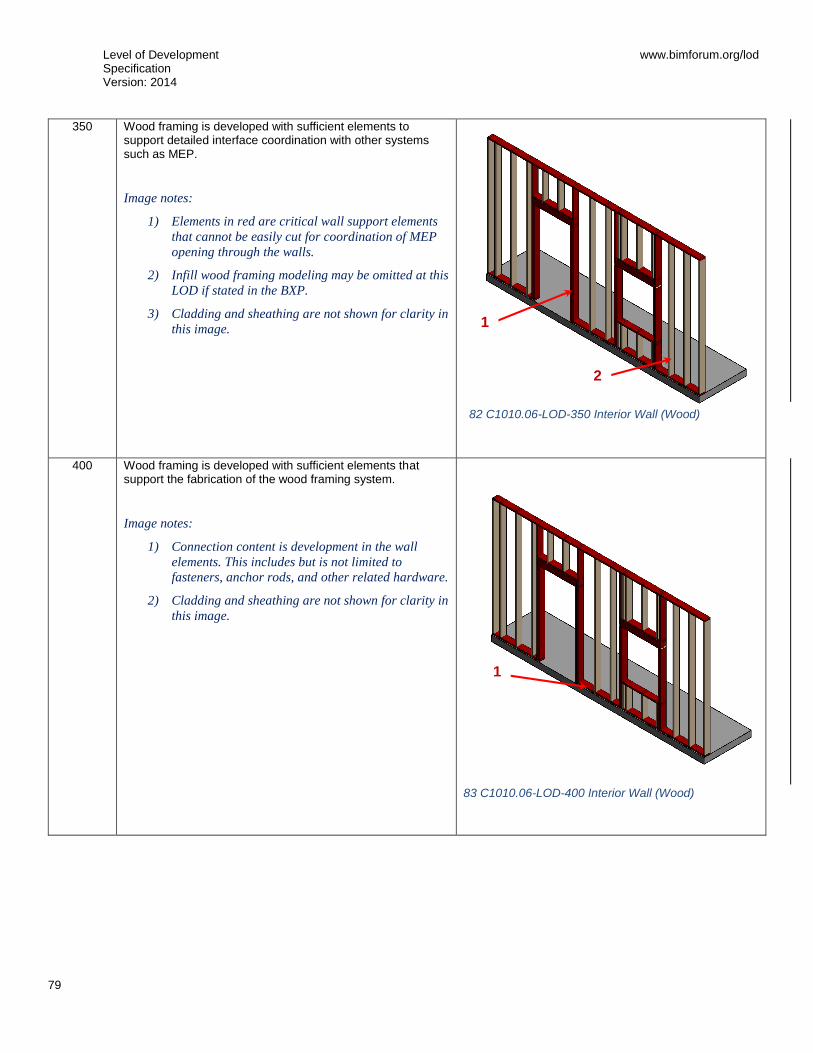
Level of Development Specification Version: 2014
www.bimforum.org/lod
79
350
Wood framing is developed with sufficient elements to support detailed interface coordination with other systems such as MEP.
Image notes:
1) Elements in red are critical wall support elements
that cannot be easily cut for coordination of MEP
opening through the walls.
2) Infill wood framing modeling may be omitted at this
LOD if stated in the BXP.
3) Cladding and sheathing are not shown for clarity in
this image.
400
Wood framing is developed with sufficient elements that support the fabrication of the wood framing system.
Image notes:
1) Connection content is development in the wall
elements. This includes but is not limited to
fasteners, anchor rods, and other related hardware.
2) Cladding and sheathing are not shown for clarity in
this image.
83 C1010.06-LOD-400 Interior Wall (Wood)
2
1
1
82 C1010.06-LOD-350 Interior Wall (Wood)

Level of Development Specification Version: 2014
www.bimforum.org/lod
80
C1010.10 – Interior Fixed Partitions 100 See C10
200 See C1010
300 Composite model assembly by type with overall thickness that accounts for framing and finish specified for the wall system. (Refer to LOD350 and LOD400 for individually modeled elements)
Wall elements are modeled to specific layouts, locations, heights, and elevation profiles. Penetrations are modeled to nominal dimensions for major wall openings such as windows, doors, and large mechanical elements.
Required non-graphic information associated with model elements includes:
Wall type
Fire rating
350 Structure and finish layers of partition assembly modeled as separate elements.
All openings modeled to rough dimensions.
Major framing elements such as king studs, kickers, diagonal bracing, and headers are modeled.
400 Element modeling to include:
Studs and tracks
Bracing
Insulation
Sheathing or wall boards
Openings/penetrations
C1010.20 – Interior Glazed Partitions 100 See C10
200 See C1010
300 Specified location and orientation of face of glass.
Nominal face dimensions and thickness of glazing.
Structural support systems of wall to be modeled.
Spacing, location, size and orientation of mullions.
Operable components defined (doors) and included in model.
350 Mullion shapes and geometry defined.
Actual anchorage layouts and types defined.
Actual panel dimensions (including seating).
400 Complete mullion extrusion profiles.
Interface details between wall systems (within) and wall and support systems.

Level of Development Specification Version: 2014
www.bimforum.org/lod
81
C1010.40 – Interior Demountable Partitions 100 See C10
200 See C1010
300 See C1010.10
350 See C1010.10 – also include hardware, accessories, and support structure.
400 See C1010.10
C1010.50 – Interior Operable Partitions 100 See C10
200 See C1010
300 Operable partition system modeled to include spatial requirements for open/storage position and closed position.
Spatial requirements for structure (overhead or below) to be modeled.
350 Major support elements (overhead or below)
Mechanical connections
400 All assembly components including tracks, panels, hardware and supports.
C1010.70 – Interior Screens Portable and open dividers.
[See C1010.10]
C1010.90 – Interior Partitions Supplementary Components Sound isolation components, firestopping, and expansion control to be included with interior partition elements above as appropriate.
These components are typically modeled as part of other assemblies listed in the tables above. Do not assign this Uniformat classification unless a supplementary component is modeled independently of another assembly.

Level of Development Specification Version: 2014
www.bimforum.org/lod
82
C1020 – Interior Windows 100 See C10
200 Windows approximate in terms of location, size, count and type. Units are modeled as a simple, monolithic component; or represented with simplified frame and glazing.
Nominal unit size is provided.
C1020.10 – Interior Operating Windows 100 See C10
200 See C1020
300 Units are modeled based on specified location and nominal size. Outer geometry of window frame elements and glazing modeled to within 1/8” [1 mm] precision.
Operation is indicated.
Non-graphic information associated with model element:
Aesthetic characteristics (finishes, glass types)
Performance characteristics (i.e. U-value, wind loading, blast resistance, structural, air, thermal, water, sound)
Functionality of the window (fixed, casement, double/single hung, awning/project out, pivot, sliding)
350 Rough opening dimensions
Attachment method of window to structure
Embed geometry
400 Frame profiles
Glazing sub-components (gaskets)
Attachment components
C1020.20 – Interior Fixed Windows [See C1020.10]
C1020.50 – Interior Special Function Windows [See C1020.10]
C1020.90 – Interior Window Supplementary Components Frames, sills, operating hardware, glazing to be included with interior window elements above as appropriate.
These components are typically modeled as part of other assemblies listed in the tables above. Do not assign this Uniformat classification unless a supplementary component is modeled independently of another assembly.

Level of Development Specification Version: 2014
www.bimforum.org/lod
83
C1030 – Interior Doors 100 See C10
200 Units are modeled as a simple, monolithic component; or represented with simple frame and panel.
Nominal unit size is provided.
C1030.10 – Interior Swinging Doors 100 See C10
200 See C1030
300 Door assemblies modeled by type to include the following:
Specific door panels and frames (if applicable).
Hardware set functionality and types are specified in non-graphic information.
Operation is specified
Spatial requirements for operation are modeled.
350 Rough opening is modeled in containing wall.
Major framing elements are modeled at jambs and head in containing wall.
Operation or mechanism enclosures are modeled, if applicable.
400 Actual frame/mullion extrusions.
Actual panel size dimensions.
All connections and interfaces modeled including brackets, supports, sealants, and thresholds.
C1030.20 – Interior Entrance Doors Exterior personnel door assemblies at interior main entrances. Includes automatic, revolving, balanced, and other special operating entrance doors, and sliding storefront wall systems. Includes Interior Door Supplementary Components as appropriate when not part of storefront system.
[See B2050.10]
C1030.25 – Interior Sliding Doors [See C1030.10]
C1030.30 – Interior Folding Doors [See C1030.10]
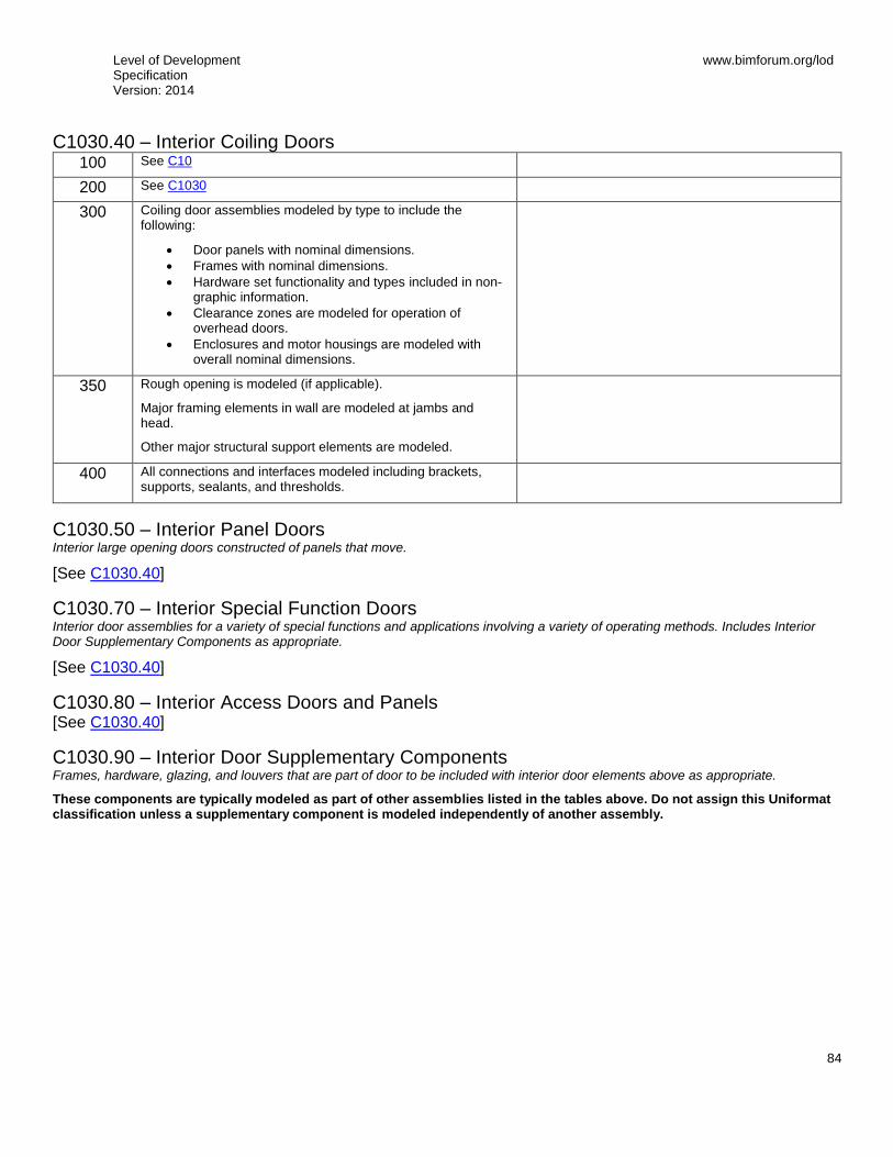
Level of Development Specification Version: 2014
www.bimforum.org/lod
84
C1030.40 – Interior Coiling Doors 100 See C10
200 See C1030
300 Coiling door assemblies modeled by type to include the following:
Door panels with nominal dimensions.
Frames with nominal dimensions.
Hardware set functionality and types included in non-graphic information.
Clearance zones are modeled for operation of overhead doors.
Enclosures and motor housings are modeled with overall nominal dimensions.
350 Rough opening is modeled (if applicable).
Major framing elements in wall are modeled at jambs and head.
Other major structural support elements are modeled.
400 All connections and interfaces modeled including brackets, supports, sealants, and thresholds.
C1030.50 – Interior Panel Doors Interior large opening doors constructed of panels that move.
[See C1030.40]
C1030.70 – Interior Special Function Doors Interior door assemblies for a variety of special functions and applications involving a variety of operating methods. Includes Interior Door Supplementary Components as appropriate.
[See C1030.40]
C1030.80 – Interior Access Doors and Panels [See C1030.40]
C1030.90 – Interior Door Supplementary Components Frames, hardware, glazing, and louvers that are part of door to be included with interior door elements above as appropriate.
These components are typically modeled as part of other assemblies listed in the tables above. Do not assign this Uniformat classification unless a supplementary component is modeled independently of another assembly.
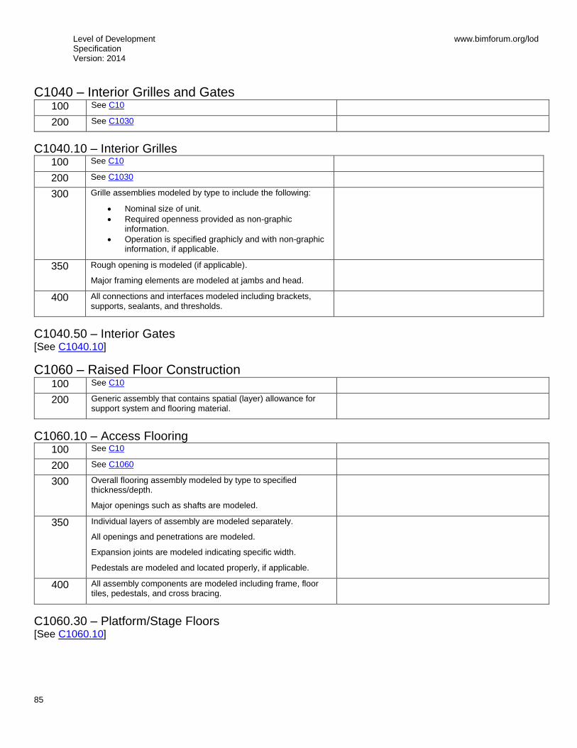
Level of Development Specification Version: 2014
www.bimforum.org/lod
85
C1040 – Interior Grilles and Gates 100 See C10
200 See C1030
C1040.10 – Interior Grilles 100 See C10
200 See C1030
300 Grille assemblies modeled by type to include the following:
Nominal size of unit.
Required openness provided as non-graphic information.
Operation is specified graphicly and with non-graphic information, if applicable.
350 Rough opening is modeled (if applicable).
Major framing elements are modeled at jambs and head.
400 All connections and interfaces modeled including brackets, supports, sealants, and thresholds.
C1040.50 – Interior Gates [See C1040.10]
C1060 – Raised Floor Construction 100 See C10
200 Generic assembly that contains spatial (layer) allowance for support system and flooring material.
C1060.10 – Access Flooring 100 See C10
200 See C1060
300 Overall flooring assembly modeled by type to specified thickness/depth.
Major openings such as shafts are modeled.
350 Individual layers of assembly are modeled separately.
All openings and penetrations are modeled.
Expansion joints are modeled indicating specific width.
Pedestals are modeled and located properly, if applicable.
400 All assembly components are modeled including frame, floor tiles, pedestals, and cross bracing.
C1060.30 – Platform/Stage Floors [See C1060.10]

Level of Development Specification Version: 2014
www.bimforum.org/lod
86
C1070 – Suspended Ceiling Construction 100 Ceiling construction is represented in other composite objects
such as floors or rooms; or, schematic model elements that are not distinguishable by type or material.
Assembly depth/thickness and locations still flexible.
200 Generic assemblies indicative of overall scope and approximate thickness/system depth of suspended ceiling.
C1070.10 – Acoustical Suspended Ceilings 100 See C1070
200 See C1070
300 Overall assembly modeled to specific system thickness including structural backing.
Location of expansion or control joints indicated, but not modeled.
350 Ceiling suspension grid is modeled.
Structural backing members including bracing/lateral framing/kickers are modeled.
Expansion or control joints are modeled to indicate specific width.
400 All assembly components are modeled including tees, hangers, support structure, and tiles.
C1070.20 – Suspended Plaster and Gypsum Board Ceilings 100 See C1070
200 See C1070
300 Overall assembly modeled to specific system thickness including framing.
Major penetrations are modeled.
350 Major bracing elements or kickers.
400 All assembly components including furring channels, hangers, lath, plaster coats, and gypsum boards.
C1070.50 – Specialty Suspended Ceilings [See C1070.10 or C1070.20]
C1070.70 – Special Function Suspended Ceilings [See C1070.10 or C1070.20]
C1070.90 – Ceiling Suspension Components Hangers and framing to suspend ceiling and sound isolation components to be included with suspended ceiling construction elements above as appropriate.
These components are typically modeled as part of other assemblies listed in the tables above. Do not assign this Uniformat classification unless a supplementary component is modeled independently of another assembly.

Level of Development Specification Version: 2014
www.bimforum.org/lod
87
C1090 – Interior Specialties 100 See C10
200 Generic model elements with approximate nominal size.
Placement and quantity remains flexible.
Required non-graphic information associated with model elements includes included with element:
Type of object
C1090.10 – Interior Railings and Handrails 100 See C10
200 Generic model element representing approximate overall height and location of railing/handrail.
300 Railing/handrail systems modeled by type to include:
All horizontal rails
All vertical posts/balusters
350 Mounting/attachment components
400 All assembly components including fasteners and supports.

Level of Development Specification Version: 2014
www.bimforum.org/lod
88
C1090.15 – Interior Louvers Interior louvers, and other items for ventilation which are not an integral part of the mechanical system. Includes operable and stationary louvers.
100 See C10
200 Generic model element that is indicative of approximate area and location of louver.
300 Louver assembly modeled by type, indicative of area and location of intended louver/vent.
Includes accurate frame (boundary dimensions) and blades.
Opening for louver is cut from host wall.
Performance level defined in non-graphic information (e.g. storm proof or not, free air).
350 Rough opening is modeled (if applicable)
Major framing elements are modeled at jambs and head.
Connection points are modeled.
400 All connections and interfaces modeled including brackets, supports, and sealants.
C1090.20 – Information Specialties Visual display units, display cases, directories, interior signage, telephone specialties, and informational kiosks.
[See Fundamental LOD Definitions]
C1090.25 – Compartments and Cubicles Manufactured compartments and cubicles for specific purposes. Includes toilet compartments, shower stalls, etc.
[See Fundamental LOD Definitions]
C1090.30 – Service Walls Wall assemblies and wall-mounted units incorporating services.
[See C1010.10]
C1090.35 – Wall and Door Protection Manufactured protective devices for walls and doors. Includes corner guards, bumper guards, and protective wall covering.
[See Fundamental LOD Definitions]
C1090.40 – Toilet, Bath and Laundry Accessories Manufactured items for use in conjunction with toilets, baths, and laundries.
[See Fundamental LOD Definitions]
C1090.45 – Interior Gas Lighting [See Fundamental LOD Definitions]
C1090.50 – Fireplaces and Stoves [See Fundamental LOD Definitions]
Level of Development Specification Version: 2014
www.bimforum.org/lod
89
C1090.60 – Safety Specialties [See Fundamental LOD Definitions]
C1090.70 – Storage Specialties [See Fundamental LOD Definitions]
C1090.90 – Other Interior Specialties [See Fundamental LOD Definitions]

Level of Development Specification Version: 2014
www.bimforum.org/lod
90
C20 Interior Finishes 100 Non-graphic information attached to model elements providing
assumptions about proposed finish materials.
C2010 – Wall Finishes 100 See C20
200 Generic materials by type (e.g. tile or paneling), approximate thickness and scope in elevation.
Generally, materials over 0.25” (10mm) thick are modeled.
300 Materials are modeled based on specific types (e.g. Tile type CT-1).
Thickness and scope are accurately modeled.
350 Additional non-graphic information to include:
Manufacturer
Model
400 Pattern layouts
Expansion/control joints
Edges
C2010.10 –Tile Wall Finish [See C2010]
C2010.20 – Wall Paneling [See C2010]
C2010.30 – Wall Coverings [See C2010]
C2010.35 – Wall Carpeting [See C2010]
C2010.50 – Stone Facing [See C2010]
C2010.60 – Special Wall Surfacing [See C2010]
C2010.70 – Wall Painting and Coating [See C2010]
C2010.80 – Acoustical Wall Treatment [See C2010]
C2010.90 – Wall Finish Supplementary Components Furring to be included with wall finish elements above as appropriate.
[See C1010]
Level of Development Specification Version: 2014
www.bimforum.org/lod
91
C2020 – Interior Fabrications [See Fundamental LOD Definitions]
C2030 – Flooring [See C2010]
C2040 – Stair Finishes [See C2010]
C2050 – Ceiling Finishes [See C1070]
Level of Development Specification Version: 2014
www.bimforum.org/lod
92
D: SERVICES
D10 Conveying 100 Schematic model elements that are not distinguishable by type
or material.
Component sizes and locations still flexible.
D1010 – Vertical Conveying Systems 100 See D10
200 Generic representation of the system envelope, including critical path of travel zones.
D1010.10 – Elevators 100 See D10
200 See D1010
300 Specific system elements modeled by type, including all path of travel zones.
Pits and/or control rooms and associated equipment to be modeled if applicable.
Major structural support elements modeled.
Connections to mechanical or electrical services.
Non-graphic information to be included with modeled elements:
Type code (referenced in specifications)
ClearWidth
ClearDepth
ClearHeight
350 Sizing adjusted to the actual manufacturer specifications.
Guiding tracks/rails
Service/access zones
400 All connections, supports, framing, and other supplementary components.
D1010.20 – Lifts [See D1010.10]
D1010.30 – Escalators [See D1010.10]
D1010.50 – Dumbwaiters [See D1010.10]
D1010.60 – Moving Ramps [See D1010.10]
Level of Development Specification Version: 2014
www.bimforum.org/lod
93
D1030 – Horizontal Conveying [See D1010.10]
D1030.10 – Moving Walks [See D1010.10]
D1030.30 – Turntables [See D1010.10]
D1030.50 – Passenger Loading Bridges [See D1010.10]
D1030.70 – People Movers [See D1010.10]
D1050 – Material Handling 100 See D10
200 Generic representation of the material handling system envelope, including critical path of travel zones.
D1050.10 – Cranes 100 See D10
200 See D1050
300 Specific system elements modeled by type, including all path of travel/boom swing zones.
Lay-down/pick-up zones are modeled.
Major structural support elements modeled.
Connections to mechanical or electrical services.
Non-graphic information to be associated with modeled elements:
Type code
350 Sizing adjusted to the actual manufacturer specifications.
Guiding tracks/rails
Service/access zones
400 All connections, supports, framing, and other supplementary components.
D1050.20 – Hoists [See D1050.10]
D1050.30 – Derrecks [See D1050.10]
D1050.40 – Conveyors [See D1050.10]

Level of Development Specification Version: 2014
www.bimforum.org/lod
94
D1050.50 – Baggage Handling Equipment 100 See D10
200 See D1050
300 See Fundamental LOD Definitions
350 See Fundamental LOD Definitions
400 See Fundamental LOD Definitions
D1050.60 – Chutes [See D1050.10]

Level of Development Specification Version: 2014
www.bimforum.org/lod
95
D1050.70 – Pneumatic Tube Systems 100 Diagrammatic elements or quantitative call outs;
conceptual and/or schematic flow diagrams;
Non-graphic information associated with model elements includes minimal design performance information.
200 Generic elements;
schematic layout with approximate size, shape, and location of equipment and tubing;
Non-graphic information associated with model elements includes design performance information.
85 D1050.70-LOD-200 Pneumatic Tube Systems
300 Modeled as design-specified elements;
specified size, shape, spacing, and location of equipment and tubing;
approximate allowances for spacing and clearances required for all specified hangers, supports, vibration and seismic control that are to be utilized in the layout of all equipment and tubing;
actual access/code clearance requirements modeled.
86 D1050.70-LOD-300 Pneumatic Tube Systems
350 Modeled as actual construction elements;
actual size, shape, spacing, and location/connections of equipment and tubing;
actual size, shape, spacing, and clearances required for all hangers, supports, vibration and seismic control that are utilized in the layout of all equipment and tubing;
floor and wall penetrations modeled.
87 D1050.70-LOD-350 Pneumatic Tube Systems
84 D1050.70-LOD-100 Pneumatic Tube Systems

Level of Development Specification Version: 2014
www.bimforum.org/lod
96
400
Supplementary components added to the model required for fabrication and field installation
88 D1050.70-LOD-400 Pneumatic Tube Systems
D1080 – Operable Access Systems [See Fundamental LOD Definitions]
D1080.10 – Suspended Scaffolding [See Fundamental LOD Definitions]
D1080.20 – Rope Climbers [See Fundamental LOD Definitions]
D1080.30 – Elevating Platforms [See Fundamental LOD Definitions]
D1080.40 – Powered Scaffolding [See Fundamental LOD Definitions]
D1080.50 – Building Envelope Access [See Fundamental LOD Definitions]
Level of Development Specification Version: 2014
www.bimforum.org/lod
97
D20 Plumbing 100 Diagrammatic or schematic model elements;
conceptual and/or schematic layout/flow diagram;
design performance parameters as defined in the BIMXP to be associated with model elements as non-graphic information.
D2010 – Domestic Water Distribution 100 See D20
200 Schematic layout of generic model elements with approximate size, shape, and location of elements;
approximate access/code clearance requirements;
shaft requirements modeled;
design performance parameters as defined in the BIMXP to be associated with model elements as non-graphic information.

Level of Development Specification Version: 2014
www.bimforum.org/lod
98
D2010.10 – Facility Potable-Water Storage Tanks 100 See D20
200 Schematic layout with approximate size, shape, and location of tank(s);
approximate access/code clearance requirements modeled;
design performance parameters as defined in the BIMXP to be associated with model elements as non-graphic information.
89 D2010.10-LOD-200 Facility Potable-Water Storage Tanks
300 Modeled as design-specified size, shape, spacing, and location of tank(s);
approximate allowances for spacing and clearances required for all specified anchors, supports, vibration and seismic control that are utilized in the layout of tanks(s);
actual access/code clearance requirements modeled.
90 D2010.10-LOD-300 Facility Potable-Water Storage Tanks
350 Modeled as actual construction elements size and shape, spacing, and location/connections of tank(s) actual size and
shape, spacing, and clearances required for all specified anchors, supports, vibration and seismic control that are utilized in the layout of tanks(s).
91 D2010.10-LOD-350 Facility Potable-Water Storage Tanks
400 Supplementary components added to the model required for fabrication and field installation.
92 D2010.10-LOD-400 Facility Potable-Water Storage Tanks

Level of Development Specification Version: 2014
www.bimforum.org/lod
99
D2010.20 – Domestic Water Equipment 100 See D20
93 D2010.20-LOD-100 Domestic Water Equipment
200 Schematic layout with approximate size, shape, and location of equipment; approximate access/code clearance requirements modeled;
design performance parameters as defined in the BIMXP to be associated with model elements as non-graphic information.
94 D2010.20-LOD-200 Domestic Water Equipment
300 Modeled as design-specified size, shape, spacing, and location of equipment;
approximate allowances for spacing and clearances required for all specified anchors, supports, vibration and seismic control that are utilized in the layout of equipment;
actual access/code clearance requirements modeled.
95 D2010.20-LOD-300 Domestic Water Equipment
350 Modeled as actual construction elements size, shape, spacing, and location/connections of equipment;
actual size, shape, spacing, and clearances required for all specified anchors, supports, vibration and seismic control that are utilized in the layout of equipment.
96 D2010.20-LOD-350 Domestic Water Equipment
400 See D2010.10
97 D2010.20-LOD-400 Domestic Water Equipment

Level of Development Specification Version: 2014
www.bimforum.org/lod
100
D2010.40 – Domestic Water Piping 100 Diagrammatic or schematic model elements;
conceptual and/or schematic flow diagrams;
design performance parameters as defined in the BIMXP to be associated with model elements as non-graphic information.
200 Schematic layout with approximate size, shape, and location of mains and risers;
shaft requirements modeled;
design performance parameters as defined in the BIMXP to be associated with model elements as non-graphic information.
98 D2010.40-LOD-200 Domestic Water Piping
300 Modeled as design-specified size, shape, spacing, and location of pipe, valves, fittings, and insulation for risers, mains, and branches;
approximate allowances for spacing and clearances required for all specified hangers, supports, vibration and seismic control that are to be utilized in the layout of all risers, mains, and branches;
actual access/code clearance requirements modeled.
99 D2010.40-LOD-300 Domestic Water Piping
350 Modeled as actual construction elements;
actual size, shape, spacing, and location/connections of pipe, valves, fittings, and insulation for risers, mains, and branches;
actual size, shape, spacing, and clearances required for all hangers, supports, vibration and seismic control that are utilized in the layout of all risers, mains, and branches;
actual floor and wall penetrations modeled.
100 D2010.40-LOD-350 Domestic Water Piping
400 See D2010.10
101 D2010.40-LOD-400 Domestic Water Piping

Level of Development Specification Version: 2014
www.bimforum.org/lod
101
D2010.60 – Plumbing Fixtures 100 See D20
200 Schematic layout with approximate size, shape, and location of fixtures;
carrier and wall width requirements modeled;
design performance parameters as defined in the BIMXP to be associated with model elements as non-graphic information.
102 D2010.60-LOD-200 Plumbing Fixtures
300 Modeled as design-specified size, shape, spacing, and location of fixtures;
approximate allowances for spacing and clearances required for all specified supports that are to be utilized in the layout of all fixtures;
actual access/code clearance requirements modeled.
103 D2010.60-LOD-200 Plumbing Fixtures
350 Modeled as actual construction elements size, shape, spacing, and location/connections of fixtures/carriers;
actual size, shape, spacing, and clearances required for all supports that are utilized in the layout of all fixtures.
104 D2010.60-LOD-350 Plumbing Fixtures
400 See D2010.10
105 D2010.60-LOD-400 Plumbing Fixtures

Level of Development Specification Version: 2014
www.bimforum.org/lod
102
D2010.90 – Domestic Water Distribution Supplementary Components Includes expansion fittings, meters, gages, valves, hangers, supports, heat tracing, vibration and seismic controls.
These components are typically modeled as part of other assemblies listed in the tables above. Do not assign this Uniformat classification unless a supplementary component is modeled independently of another assembly.
D2020 – Sanitary Drainage 100 See D20
200 See D2010

Level of Development Specification Version: 2014
www.bimforum.org/lod
103
D2020.10 – Sanitary Sewerage Equipment 100 See D20
200 Schematic layout with approximate size, shape, and location of equipment;
design performance parameters as defined in the BIMXP to be associated with model elements as non-graphic information.
106 D2020.10-LOD-200 Sanitary Sewerage Equipment
300 Modeled as design specified size, shape, spacing, and location of equipment;
approximate allowances for spacing and clearances required for all specified anchors, supports, vibration and seismic control that are utilized in the layout of equipment; actual access/code clearance requirements modeled.
107
D2020.10-LOD-300 Sanitary Sewerage Equipment
350 Actual size, shape, spacing, and clearances required for all specified anchors, supports, vibration and seismic control that are utilized in the layout of equipment;
actual access/code clearance requirements modeled.
108 D2020.10-LOD-350 Sanitary Sewerage Equipment
400 Supplementary components added to the model required for fabrication and field installation
109 D2020.10-LOD-400 Sanitary Sewerage Equipment

Level of Development Specification Version: 2014
www.bimforum.org/lod
104
D2020.30 – Sanitary Sewerage Piping 100 See D20
200 Schematic layout with approximate size, shape, and location of mains and risers; shaft requirements modeled; design performance parameters as defined in the BIMXP to be associated with model elements as non-graphic information.
110 D2020.30-LOD-200 Sanitary Sewerage Piping
300 Modeled as design-specified size, shape, spacing, location, and slope of pipe, valves, fittings, and insulation for risers, mains, and branches;
approximate allowances for spacing and clearances required for all specified hangers, supports, vibration and seismic control that are to be utilized in the layout of all risers, mains, and branches;
actual access/code clearance requirements modeled
111 D2020.30-LOD-300 Sanitary Sewerage Piping
350 Modeled as actual construction elements;
actual size, shape, spacing, location, connections, and slope of pipe, valves, fittings, and insulation for risers, mains, and branches;
actual size, shape, spacing, and clearances required for all hangers, supports, vibration and seismic control that are utilized in the layout of all risers, mains, and branches;
actual floor and wall penetrations modeled.
112 D2020.30-LOD-350 Sanitary Sewerage Piping
400
See D2020.10
113 D2020.30-LOD-400 Sanitary Sewerage Piping

Level of Development Specification Version: 2014
www.bimforum.org/lod
105
D2020.90 – Sanitary Drainage Supplementary Components Includes expansion fittings, meters, gages, valves, hangers, supports, heat tracing, vibration and seismic controls.
These components are typically modeled as part of other assemblies listed in the tables above. Do not assign this Uniformat classification unless a supplementary component is modeled independently of another assembly.
D2030 – Building Support Plumbing Systems 100 See D20
200 See D2010
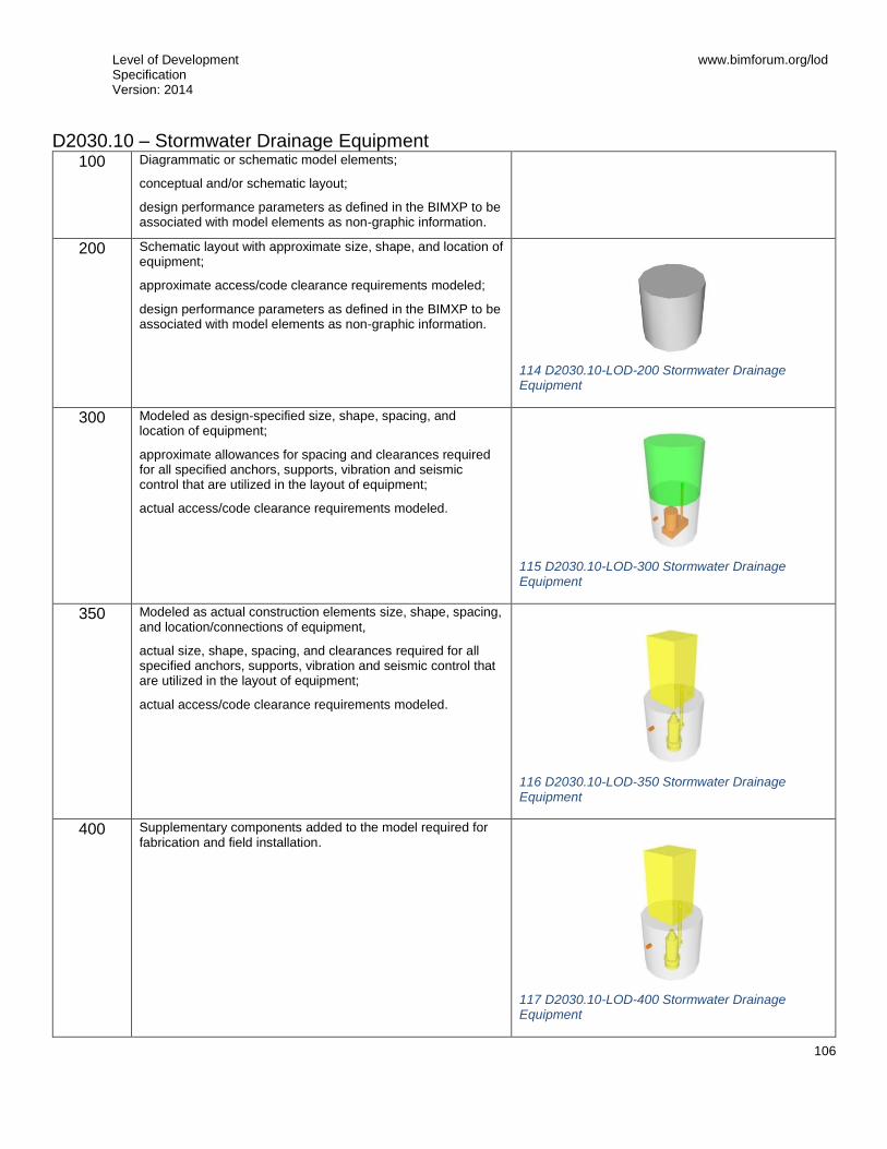
Level of Development Specification Version: 2014
www.bimforum.org/lod
106
D2030.10 – Stormwater Drainage Equipment 100 Diagrammatic or schematic model elements;
conceptual and/or schematic layout;
design performance parameters as defined in the BIMXP to be associated with model elements as non-graphic information.
200 Schematic layout with approximate size, shape, and location of equipment;
approximate access/code clearance requirements modeled;
design performance parameters as defined in the BIMXP to be associated with model elements as non-graphic information.
114 D2030.10-LOD-200 Stormwater Drainage Equipment
300 Modeled as design-specified size, shape, spacing, and location of equipment;
approximate allowances for spacing and clearances required for all specified anchors, supports, vibration and seismic control that are utilized in the layout of equipment;
actual access/code clearance requirements modeled.
115 D2030.10-LOD-300 Stormwater Drainage Equipment
350 Modeled as actual construction elements size, shape, spacing, and location/connections of equipment,
actual size, shape, spacing, and clearances required for all specified anchors, supports, vibration and seismic control that are utilized in the layout of equipment;
actual access/code clearance requirements modeled.
116 D2030.10-LOD-350 Stormwater Drainage Equipment
400 Supplementary components added to the model required for fabrication and field installation.
117 D2030.10-LOD-400 Stormwater Drainage Equipment

Level of Development Specification Version: 2014
www.bimforum.org/lod
107
D2030.20 – Stormwater Drainage Piping 100 See D20
200 Schematic layout with approximate size, shape, and location of mains and risers;
shaft requirements modeled;
design performance parameters as defined in the BIMXP to be associated with model elements as non-graphic information.
118 D2030.20-LOD-200 Stormwater Drainage Piping
300 Modeled as design-specified size, shape, spacing, location, and slope of pipe, valves, fittings, and insulation for risers, mains, and branches;
approximate allowances for spacing and clearances required for all specified hangers, supports, vibration and seismic control that are to be utilized in the layout of all risers, mains, and branches;
actual access/code clearance requirements modeled.
119 D2030.20-LOD-300 Stormwater Drainage Piping
350 Modeled as actual size, shape, spacing, location, connections, and slope of pipe, valves, fittings, and insulation for risers, mains, and branches;
actual size and shape, spacing, and clearances required for all hangers, supports, vibration and seismic control that are utilized in the layout of all risers, mains, and branches;
actual floor and wall penetrations modeled.
120 D2030.20-LOD-350 Stormwater Drainage Piping
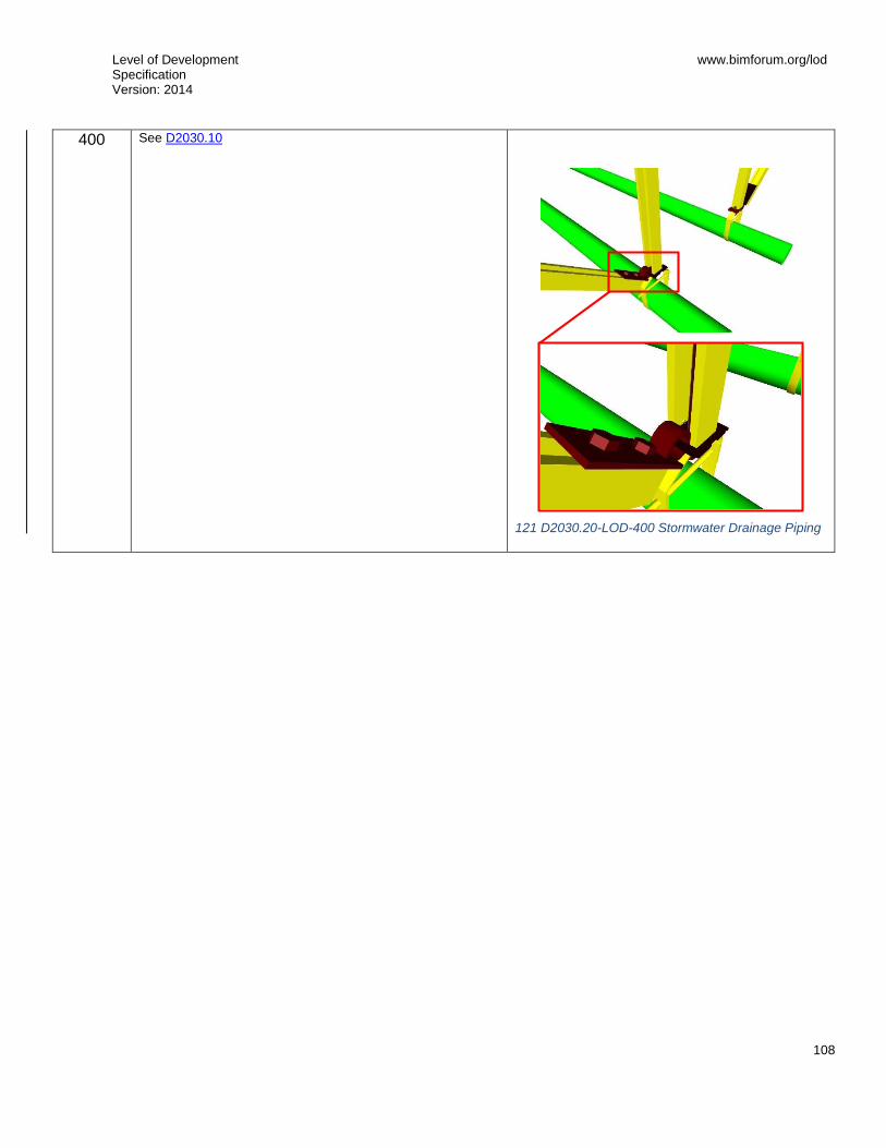
Level of Development Specification Version: 2014
www.bimforum.org/lod
108
400
See D2030.10
121 D2030.20-LOD-400 Stormwater Drainage Piping

Level of Development Specification Version: 2014
www.bimforum.org/lod
109
D2030.30 – Facility Stormwater Drains 100 See D20
200
Schematic layout with approximate size, shape, and location of components;
design performance parameters as defined in the BIMXP to be associated with model elements as non-graphic information.
122 D2030.30-LOD-200 Facility Stormwater Drains
300 Modeled as design-specified size, shape, spacing, and location of components;
approximate allowances for spacing and clearances required for all specified hangers, supports, vibration and seismic control that are to be utilized in the layout of all components;
actual access/code clearance requirements modeled.
123 D2030.30-LOD-300 Facility Stormwater Drains
350 Modeled as actual construction elements size, shape, spacing, and location/connections of components;
actual size, shape, spacing, and clearances required for all hangers, supports, vibration and seismic control that are utilized in the layout of all components.
124 D2030.30-LOD-350 Facility Stormwater Drains
400 See D2030.10
125 D2030.30-LOD-400 Facility Stormwater Drains

Level of Development Specification Version: 2014
www.bimforum.org/lod
110
D2030.60 – Gray Water Systems [See D2030.20]
D2030.90 – Building Support Plumbing System Supplementary Components Includes expansion fittings, meters, gages, valves, hangers, supports, heat tracing, vibration and seismic controls.
These components are typically modeled as part of other assemblies listed in the tables above. Do not assign this Uniformat classification unless a supplementary component is modeled independently of another assembly.
D2050 – General Service Compressed-Air [See D2060.10 – Compressed-Air Systems]
D2060 – Process Support Plumbing Systems 100 See D20
200 Schematic layout with approximate size, shape, and location of mains and risers;
shaft requirements modeled;
design performance parameters as defined in the BIMXP to be associated with model elements as non-graphic information.

Level of Development Specification Version: 2014
www.bimforum.org/lod
111
D2060.10 – Compressed-Air Systems 100 See D20
200 See D2060
126 D2060.10-LOD-200 Compressed-Air Systems
300 Modeled as design-specified size, shape, spacing, location, and slope of equipment/pipe, valves, fittings, and insulation for risers, mains, and branches;
approximate allowances for spacing and clearances required for all specified hangers, supports, vibration and seismic control that are to be utilized in the layout of all risers, mains, and branches;
actual access/code clearance requirements modeled.
127 D2060.10-LOD-300 Compressed-Air Systems
350 Modeled as actual size, shape, spacing, location, connections, and slope of equipment/pipe, valves, fittings, and insulation for risers, mains, and branches;
actual size, shape, spacing, and clearances required for all hangers, supports, vibration and seismic control that are utilized in the layout of all risers, mains, and branches;
actual floor and wall penetrations modeled.
128 D2060.10-LOD-350 Compressed-Air Systems
400 Supplementary components added to the model required for fabrication and field installation.
129 D2060.10-LOD-400 Compressed-Air Systems

Level of Development Specification Version: 2014
www.bimforum.org/lod
112
D2060.20 – Vacuum Systems [See D2060.10]
D2060.30 – Gas Systems [See D2060.10]
D2060.40 – Chemical-Waste Systems [See D2060.10]
D2060.50 – Processed Water Systems [See D2060.10]
D2060.90 – Process Support Plumbing System Supplementary Components Includes expansion fittings, meters, gages, valves, hangers, supports, heat tracing, vibration and seismic controls.
These components are typically modeled as part of other assemblies listed in the tables above. Do not assign this Uniformat classification unless a supplementary component is modeled independently of another assembly.
Level of Development Specification Version: 2014
www.bimforum.org/lod
113
D30 HVAC 100 Diagrammatic or schematic model elements;
conceptual and/or schematic layout/flow diagram;
design performance parameters as defined in the BIMXP to be associated with model elements as non-graphic information.
D3010 – Facility Fuel Systems 100 See D30
200 Schematic layout with approximate size, shape, and location of element(s);
approximate access/code clearance requirements modeled;
shaft requirements modeled;
design performance parameters as defined in the BIMXP to be associated with model elements as non-graphic information.

Level of Development Specification Version: 2014
www.bimforum.org/lod
114
D3010.10 – Fuel Piping 100 See D30
200 See D3010
130 D3010.10-200 Fuel Piping
300 Modeled as design-specified size, shape, spacing, and location of pipe, valves, fittings, and insulation for risers, mains, and branches;
approximate allowances for spacing and clearances required for all specified hangers, supports, vibration and seismic control that are to be utilized in the layout of all risers, mains, and branches;
actual access/code clearance requirements modeled.
131 D3010.10-300 Fuel Piping
350 Modeled as actual size, shape, spacing, and location/connections of pipe, valves, fittings, and insulation for risers, mains, and branches;
actual size, shape, spacing, and clearances required for all hangers, supports, vibration and seismic control that are utilized in the layout of all risers, mains, and branches;
actual floor and wall penetrations modeled.
132 D3010.10-350 Fuel Piping

Level of Development Specification Version: 2014
www.bimforum.org/lod
115
400
Supplementary components added to the model required for fabrication and field installation
133 D3010.10-400 Fuel Piping

Level of Development Specification Version: 2014
www.bimforum.org/lod
116
D3010.30 – Fuel Pumps 100 See D30
200 See D3010
300 Modeled as design-specified size, shape, spacing, and location of equipment;
approximate allowances for spacing and clearances required for all specified anchors, supports, vibration and seismic control that are utilized in the layout of equipment;
actual access/code clearance requirements modeled.
350 Modeled as actual size, shape, spacing, and location/connections of equipment;
actual size, shape, spacing, and clearances required for all specified anchors, supports, vibration and seismic control that are utilized in the layout of equipment.
400 See D3010.10

Level of Development Specification Version: 2014
www.bimforum.org/lod
117
D3010.50 – Fuel Storage Tanks 100 See D30
200 See D3010
134 D3010.50-LOD-200 Fuel Storage Tanks
300 Modeled as design-specified size, shape, spacing, and location of tank(s);
approximate allowances for spacing and clearances required for all specified anchors, supports, vibration and seismic control that are utilized in the layout of tanks(s);
actual access/code clearance requirements modeled.
135 D3010.50-LOD-300 Fuel Storage Tanks
350 Modeled as actual size, shape, spacing, and location/connections of tank(s);
actual size, shape, spacing, and clearances required for all specified anchors, supports, vibration and seismic control that are utilized in the layout of tanks(s).
136 D3010.50-LOD-350 Fuel Storage Tanks
400 See D3010.10
137 D3010.50-LOD-400 Fuel Storage Tanks
Level of Development Specification Version: 2014
www.bimforum.org/lod
118
D3020 – Heating Systems 100 See D30
200 Schematic layout with approximate size, shape, and location of element(s);
approximate access/code clearance requirements modeled;
shaft requirements modeled;
design performance parameters as defined in the BIMXP to be associated with model elements as non-graphic information.

Level of Development Specification Version: 2014
www.bimforum.org/lod
119
D3020.10 – Heat Generation 100 See D30
200 See D3020
138 D3020.10-LOD-200 Heat Generation
300 Modeled as design-specified size, shape, spacing, and location of equipment;
approximate allowances for spacing and clearances required for all specified anchors, supports, vibration and seismic control that are utilized in the layout of equipment;
actual access/code clearance requirements modeled.
139 D3020.10-LOD-300 Heat Generation
350 Modeled as actual size, shape, spacing, and location/connections of equipment,
actual size, shape, spacing, and clearances required for all specified anchors, supports, vibration and seismic control that are utilized in the layout of equipment.
140 D3020.10-LOD-350 Heat Generation
400 Supplementary components added to the model required for fabrication and field installation.
141 D3020.10-LOD-400 Heat Generation

Level of Development Specification Version: 2014
www.bimforum.org/lod
120
D3020.30 – Thermal Heat Storage [See D3020.10]
D3020.70 – Decentralized Heating Equipment [See D3020.10]
D3020.90 – Heating System Supplementary Components Includes expansion fittings, meters, gages, valves, hangers, supports, heat tracing, vibration and seismic controls.
These components are typically modeled as part of other assemblies listed in the tables above. Do not assign this Uniformat classification unless a supplementary component is modeled independently of another assembly.

Level of Development Specification Version: 2014
www.bimforum.org/lod
121
D3030 – Cooling Systems 100 See D30
200 Schematic layout with approximate size, shape, and location of element(s);
approximate access/code clearance requirements modeled;
shaft requirements modeled;
design performance parameters as defined in the BIMXP to be associated with model elements as non-graphic information.

Level of Development Specification Version: 2014
www.bimforum.org/lod
122
D3030.10 – Central Cooling 100 See D30
200 See D3030
142 D3030.10-LOD-200 Central Cooling
300 Modeled as design-specified size, shape, spacing, and location of equipment;
approximate allowances for spacing and clearances required for all specified anchors, supports, vibration and seismic control that are utilized in the layout of equipment;
actual access/code clearance requirements modeled.
143 D3030.10-LOD-300 Central Cooling
350 Modeled as actual size, shape, spacing, and location/connections of equipment;
actual size, shape, spacing, and clearances required for all specified anchors, supports, vibration and seismic control that are utilized in the layout of equipment.
144 D3030.10-LOD-350 Central Cooling
400 Supplementary components added to the model required for fabrication and field installation.
145 D3030.10-LOD-400 Central Cooling

Level of Development Specification Version: 2014
www.bimforum.org/lod
123
D3030.30 – Evaporative Air-Cooling 100 See D3030.10
200 See D3030.10
146 D3030.30-LOD-200 Evaporative Air-Cooling
300 See D3030.10
147 D3030.30-LOD-300 Evaporative Air-Cooling
350 See D3030.10
148 D3030.30-LOD-350 Evaporative Air-Cooling
400 See D3030.10
149 D3030.30-LOD-400 Evaporative Air-Cooling

Level of Development Specification Version: 2014
www.bimforum.org/lod
124
D3030.50 – Thermal Cooling Storage [See D3030.10]
D3030.70 – Decentralized Cooling [See D3030.10]
D3030.90 – Cooling System Supplementary Components Includes expansion fittings, meters, gages, valves, hangers, supports, heat tracing, vibration and seismic controls.
These components are typically modeled as part of other assemblies listed in the tables above. Do not assign this Uniformat classification unless a supplementary component is modeled independently of another assembly.
D3050 – Facility HVAC Distribution Systems 100 See D30
200 Schematic layout with approximate size, shape, and location of element(s);
approximate access/code clearance requirements modeled;
shaft requirements modeled;
design performance parameters as defined in the BIMXP to be associated with model elements as non-graphic information.

Level of Development Specification Version: 2014
www.bimforum.org/lod
125
D3050.10 – Facility Hydronic Distribution 100 See D30
200 See D3050
300 Modeled as design-specified size, shape, spacing, location, and slope of pipe, valves, fittings, and insulation for risers, mains, and branches;
approximate allowances for spacing and clearances required for all specified hangers, supports, vibration and seismic control that are to be utilized in the layout of all risers, mains, and branches;
actual access/code clearance requirements modeled.
350 Modeled as actual size, shape, spacing, location, connections, and slope of pipe, valves, fittings, and insulation for risers, mains, and branches;
actual size, shape, spacing, and clearances required for all hangers, supports, vibration and seismic control that are utilized in the layout of all risers, mains, and branches;
actual floor and wall penetrations modeled.
150 D3050.10-LOD-200 Facility Hydronic Distribution
151 D3050.10-LOD-300 Facility Hydronic Distribution
152 D3050.10-LOD-350 Facility Hydronic Distribution

Level of Development Specification Version: 2014
www.bimforum.org/lod
126
400
Supplementary components added to the model required for fabrication and field installation.
153 D3050.10-LOD-400 Facility Hydronic Distribution

Level of Development Specification Version: 2014
www.bimforum.org/lod
127
D3050.30 – Facility Steam Distribution [See D3050.10]
D3050.50 – HVAC Air Distribution 100 See D30
200 See D3050
300 Modeled as design-specified size, shape, spacing, and location of duct, dampers, fittings, and insulation for risers, mains, and branches;
approximate allowances for spacing and clearances required for all specified hangers, supports, vibration and seismic control that are to be utilized in the layout of all risers, mains, and branches;
actual access/code clearance requirements modeled.
350 Modeled as actual size, shape, spacing, and location/connections of duct, dampers, fittings, and insulation for risers, mains, and branches;
actual size, shape, spacing, and clearances required for all hangers, supports, vibration and seismic control that are utilized in the layout of all risers, mains, and branches;
actual floor and wall penetrations modeled.
400 See D3050.10
D3050.90 – Facility Distribution Systems Supplementary Components Includes expansion fittings, meters, gages, valves, hangers, supports, heat tracing, vibration and seismic controls.
These components are typically modeled as part of other assemblies listed in the tables above. Do not assign this Uniformat classification unless a supplementary component is modeled independently of another assembly.
D3060 – Ventilation 100 See D30
200 Schematic layout with approximate size, shape, and location of mains and risers;
shaft requirements modeled;
design performance parameters as defined in the BIMXP to be associated with model elements as non-graphic information.

Level of Development Specification Version: 2014
www.bimforum.org/lod
128
D3060.10 – Supply Air 100 See D30
200 See D3060
154 D3060.10-LOD-200 Supply Air
300 Modeled as design-specified size, shape, spacing, and location of duct, dampers, fittings, and insulation for risers, mains, and branches;
approximate specified allowances for spacing and clearances required for all hangers, supports, vibration and seismic control that are to be utilized in the layout of all risers, mains, and branches;
actual access/code clearance requirements modeled.
155 D3060.10-LOD-300 Supply Air
350 Modeled as actual size, shape, spacing, and location/connections of duct, dampers, fittings, and insulation for risers, mains, and branches;
actual size, shape, spacing, and clearances required for all hangers, supports, vibration and seismic control that are utilized in the layout of all risers, mains, and branches;
actual floor and wall penetrations modeled.
156 D3060.10-LOD-350 Supply Air
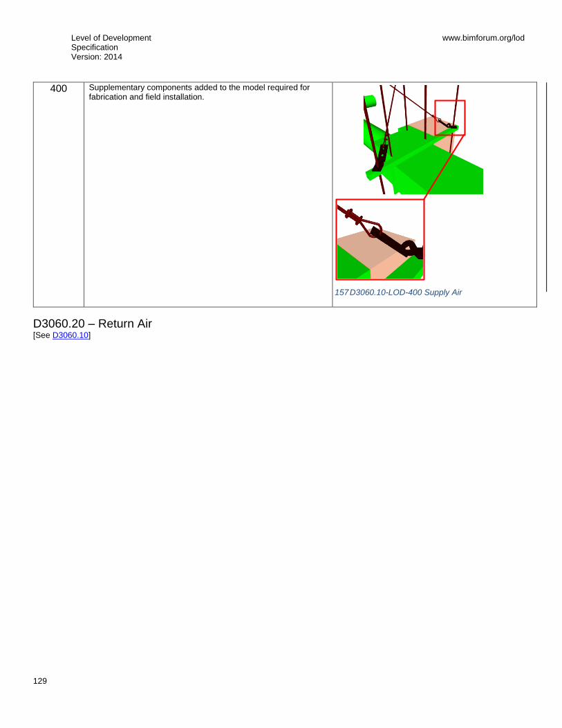
Level of Development Specification Version: 2014
www.bimforum.org/lod
129
400
Supplementary components added to the model required for fabrication and field installation.
D3060.20 – Return Air [See D3060.10]
157 D3060.10-LOD-400 Supply Air
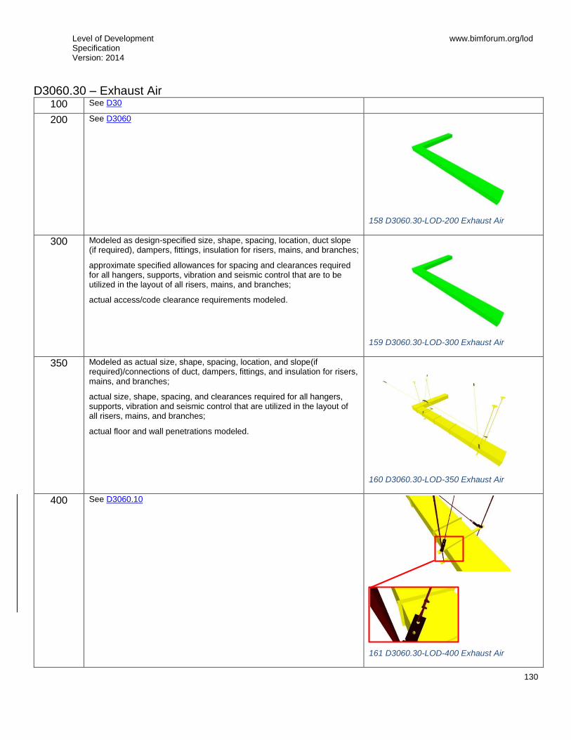
Level of Development Specification Version: 2014
www.bimforum.org/lod
130
D3060.30 – Exhaust Air 100 See D30
200 See D3060
158 D3060.30-LOD-200 Exhaust Air
300 Modeled as design-specified size, shape, spacing, location, duct slope (if required), dampers, fittings, insulation for risers, mains, and branches;
approximate specified allowances for spacing and clearances required for all hangers, supports, vibration and seismic control that are to be utilized in the layout of all risers, mains, and branches;
actual access/code clearance requirements modeled.
159 D3060.30-LOD-300 Exhaust Air
350 Modeled as actual size, shape, spacing, location, and slope(if required)/connections of duct, dampers, fittings, and insulation for risers, mains, and branches;
actual size, shape, spacing, and clearances required for all hangers, supports, vibration and seismic control that are utilized in the layout of all risers, mains, and branches;
actual floor and wall penetrations modeled.
160 D3060.30-LOD-350 Exhaust Air
400
See D3060.10
161 D3060.30-LOD-400 Exhaust Air

Level of Development Specification Version: 2014
www.bimforum.org/lod
131
D3060.40 – Outside Air [See D3060.10]
D3060.60 – Air-to-Air Energy Recovery [See D3060.10]
D3060.70 – HVAC Air Cleaning [See D3060.10]
D3060.90 – Ventilation Supplementary Components Includes expansion fittings, meters, gages, valves, hangers, supports, heat tracing, vibration and seismic controls.
These components are typically modeled as part of other assemblies listed in the tables above. Do not assign this Uniformat classification unless a supplementary component is modeled independently of another assembly.
D3070 – Special Purpose HVAC Systems 100 See D30
200 Schematic layout with approximate size, shape, and location of components;
design performance parameters as defined in the BIMXP to be associated with model elements as non-graphic information.
D3070.10 – Snow Melting 100 See D30
200 See D3070
300 Modeled as design-specified size, shape, spacing, and location of supplementary components;
approximate allowances for spacing and clearances required for all specified hangers, supports, vibration and seismic control that are to be utilized in the layout of all supplementary components;
actual access/code clearance requirements modeled.
350 Modeled as actual size, shape, spacing, and location/connections of supplementary components;
actual size, shape, spacing, and clearances required for all hangers, supports, vibration and seismic control that are utilized in the layout of all supplementary components.
400 Supplementary components added to the model required for fabrication and field installation.
D40 Fire Protection 100 Diagrammatic or schematic model elements;
conceptual and/or schematic layout/flow diagram;
design performance parameters as defined in the BIMXP to be associated with model elements as non-graphic information.
D4010 – Fire Suppression 100 See D40
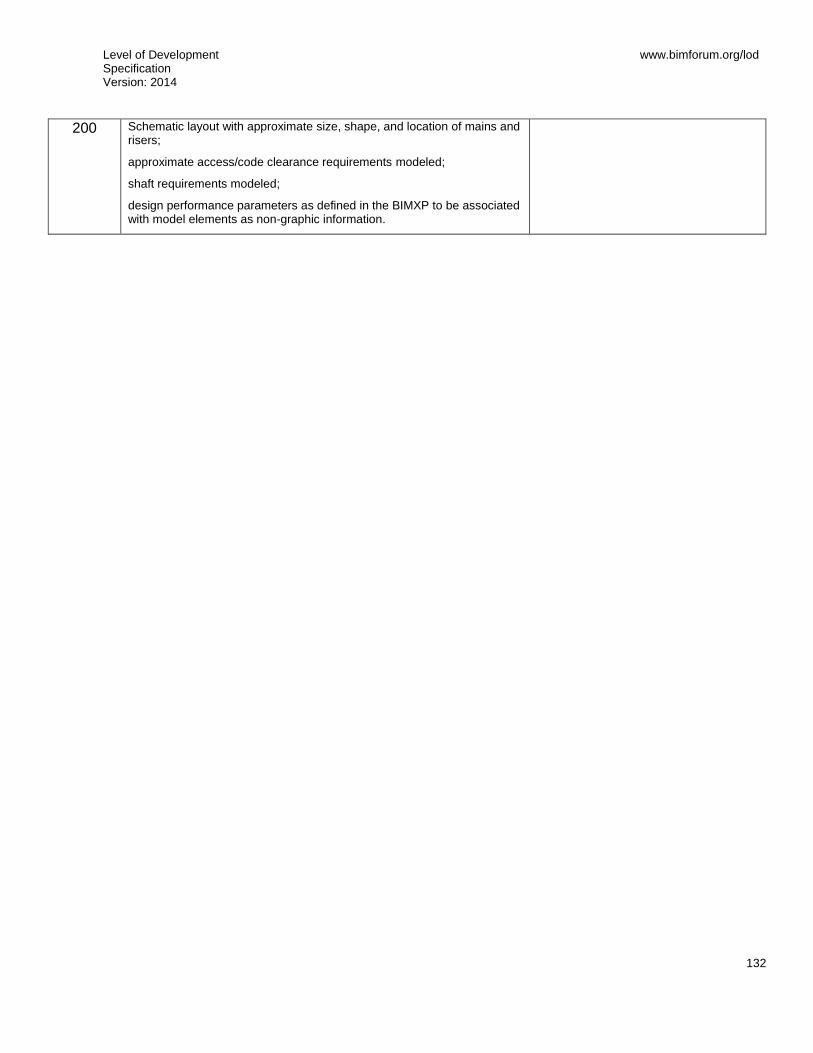
Level of Development Specification Version: 2014
www.bimforum.org/lod
132
200 Schematic layout with approximate size, shape, and location of mains and risers;
approximate access/code clearance requirements modeled;
shaft requirements modeled;
design performance parameters as defined in the BIMXP to be associated with model elements as non-graphic information.
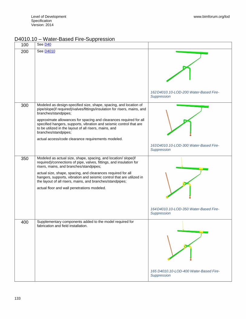
Level of Development Specification Version: 2014
www.bimforum.org/lod
133
D4010.10 – Water-Based Fire-Suppression 100 See D40
200 See D4010
162 D4010.10-LOD-200 Water-Based Fire-Suppression
300 Modeled as design-specified size, shape, spacing, and location of pipe/slope(if required)/valves/fittings/insulation for risers, mains, and branches/standpipes;
approximate allowances for spacing and clearances required for all specified hangers, supports, vibration and seismic control that are to be utilized in the layout of all risers, mains, and branches/standpipes;
actual access/code clearance requirements modeled.
163 D4010.10-LOD-300 Water-Based Fire-Suppression
350 Modeled as actual size, shape, spacing, and location/ slope(if required)/connections of pipe, valves, fittings, and insulation for risers, mains, and branches/standpipes;
actual size, shape, spacing, and clearances required for all hangers, supports, vibration and seismic control that are utilized in the layout of all risers, mains, and branches/standpipes;
actual floor and wall penetrations modeled.
164 D4010.10-LOD-350 Water-Based Fire-Suppression
400 Supplementary components added to the model required for fabrication and field installation.
165 D4010.10-LOD-400 Water-Based Fire-Suppression
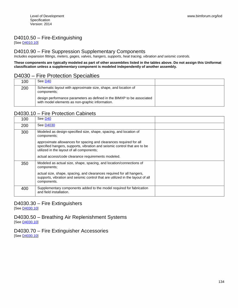
Level of Development Specification Version: 2014
www.bimforum.org/lod
134
D4010.50 – Fire-Extinguishing [See D4010.10]
D4010.90 – Fire Suppression Supplementary Components Includes expansion fittings, meters, gages, valves, hangers, supports, heat tracing, vibration and seismic controls.
These components are typically modeled as part of other assemblies listed in the tables above. Do not assign this Uniformat classification unless a supplementary component is modeled independently of another assembly.
D4030 – Fire Protection Specialties 100 See D40
200 Schematic layout with approximate size, shape, and location of components;
design performance parameters as defined in the BIMXP to be associated with model elements as non-graphic information.
D4030.10 – Fire Protection Cabinets 100 See D40
200 See D4030
300 Modeled as design-specified size, shape, spacing, and location of components;
approximate allowances for spacing and clearances required for all specified hangers, supports, vibration and seismic control that are to be utilized in the layout of all components;
actual access/code clearance requirements modeled.
350 Modeled as actual size, shape, spacing, and location/connections of components;
actual size, shape, spacing, and clearances required for all hangers, supports, vibration and seismic control that are utilized in the layout of all components.
400 Supplementary components added to the model required for fabrication and field installation.
D4030.30 – Fire Extinguishers [See D4030.10]
D4030.50 – Breathing Air Replenishment Systems [See D4030.10]
D4030.70 – Fire Extinguisher Accessories [See D4030.10]
Level of Development Specification Version: 2014
www.bimforum.org/lod
135
D50 Electrical 100 Diagrammatic or schematic model elements:
conceptual and/or schematic layout;
design performance parameters as defined in the BIMXP to be associated with model elements as non-graphic information.
D5010 – Facility Power Generation 100 See D50
200 Schematic layout with approximate size, shape, and location of equipment;
approximate access/code clearance requirements modeled;
design performance parameters as defined in the BIMXP to be associated with model elements as non-graphic information.
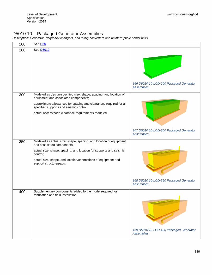
Level of Development Specification Version: 2014
www.bimforum.org/lod
136
D5010.10 – Packaged Generator Assemblies Description: Generator, frequency changers, and rotary converters and uninterruptible power units.
100 See D50
200 See D5010
166 D5010.10-LOD-200 Packaged Generator Assemblies
300 Modeled as design-specified size, shape, spacing, and location of equipment and associated components;
approximate allowances for spacing and clearances required for all specified supports and seismic control;
actual access/code clearance requirements modeled.
167 D5010.10-LOD-300 Packaged Generator Assemblies
350 Modeled as actual size, shape, spacing, and location of equipment and associated components;
actual size, shape, spacing, and location for supports and seismic control;
actual size, shape, and location/connections of equipment and support structure/pads.
168 D5010.10-LOD-350 Packaged Generator Assemblies
400 Supplementary components added to the model required for fabrication and field installation.
169 D5010.10-LOD-400 Packaged Generator Assemblies

Level of Development Specification Version: 2014
www.bimforum.org/lod
137
D5010.20 – Battery Equipment Description: Batteries, battery racks, battery chargers, static power converters, uninterruptible power supplies, and accessories.
[See D5010.10]
D5010.30 – Photovoltaic Collectors Description: Solar cells to convert sunlight to electricity.
[See D5010.10]
D5010.40 – Fuel Cells Description: Fuel cell electricity generating equipment.
[See D5010.10]
D5010.70 – Transfer Switches Description: Switches that transfer from one source of electricity to another.
[See D5010.10]
D5020 – Electrical Service and Distribution 100 See D50
200 Schematic layout with approximate size, shape, and location of equipment;
approximate access/code clearance requirements modeled;
design performance parameters as defined in the BIMXP to be associated with model elements as non-graphic information.

Level of Development Specification Version: 2014
www.bimforum.org/lod
138
D5020.10 – Electrical Service Entrance Description: Meters, substations, transformers, switchgear, switchboards, and protective devices where electrical power enters structure.
100 See D50
200 See D5020
300 Modeled as design-specified size, shape, spacing, and location of equipment and associated components;
approximate allowances for spacing and clearances required for all specified supports and seismic control;
actual access/code clearance requirements modeled.
170 D5020.10-LOD-300 Electrical Service Entrance
350 Modeled as actual size, shape, spacing, and location of equipment and associated components;
actual size, shape, spacing, and location for supports and seismic control;
actual size, shape, and location/connections of equipment and support structure/pads.
171 D5020.10-LOD-350 Electrical Service Entrance
400 Supplementary components added to the model required for fabrication and field installation.
172 D5020.10-LOD-400 Electrical Service Entrance
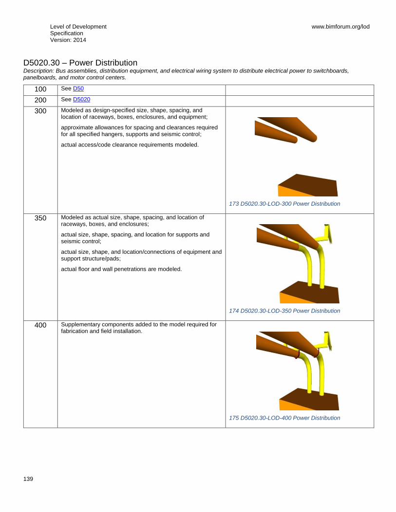
Level of Development Specification Version: 2014
www.bimforum.org/lod
139
D5020.30 – Power Distribution Description: Bus assemblies, distribution equipment, and electrical wiring system to distribute electrical power to switchboards, panelboards, and motor control centers.
100 See D50
200 See D5020
300 Modeled as design-specified size, shape, spacing, and location of raceways, boxes, enclosures, and equipment;
approximate allowances for spacing and clearances required for all specified hangers, supports and seismic control;
actual access/code clearance requirements modeled.
173 D5020.30-LOD-300 Power Distribution
350 Modeled as actual size, shape, spacing, and location of raceways, boxes, and enclosures;
actual size, shape, spacing, and location for supports and seismic control;
actual size, shape, and location/connections of equipment and support structure/pads;
actual floor and wall penetrations are modeled.
174 D5020.30-LOD-350 Power Distribution
400 Supplementary components added to the model required for fabrication and field installation.
175 D5020.30-LOD-400 Power Distribution

Level of Development Specification Version: 2014
www.bimforum.org/lod
140
D5020.70 – Facility Grounding Description: Raceways, wiring and devices for grounding and bonding an electrical distribution system.
100 See D50
200 See D5020
300 Modeled as design-specified size, shape, spacing, and location of raceways, boxes, enclosures, and the electrical equipment and end-devices served;
approximate allowances for spacing and clearances required for all specified hangers, supports, and seismic control;
actual access/code clearance requirements modeled.
350 Modeled as actual size, shape, spacing, and location of raceways, boxes, enclosures, and the electrical equipment and end-devices served;
actual size, shape, spacing, and location for supports and seismic control;
actual floor and wall penetrations are modeled.
400 Supplementary components added to the model required for fabrication and field installation.
D5030 – General Purpose Electrical Power 100 See D50
200 Schematic layout with approximate size, shape, and location of equipment;
approximate access/code clearance requirements modeled;
design performance parameters as defined in the BIMXP to be associated with model elements as non-graphic information.

Level of Development Specification Version: 2014
www.bimforum.org/lod
141
D5030.10 – Branch Wiring System Description: Raceways, ducts, cable trays, and wiring to deliver power from branch panelboards to the point of use.
100 See D50
200 See D5030
300 Modeled as design-specified size, shape, spacing, and location of raceways, boxes, and enclosures;
approximate allowances for spacing and clearances required for all specified hangers, supports and seismic control;
actual access/code clearance requirements modeled.
176 D5030.10-LOD-300 Branch Wiring System
350 Modeled as actual size, shape, spacing, and location of raceways, boxes, enclosures;
actual size, shape, spacing, and location for supports and seismic control;
actual floor and wall penetrations are modeled.
177 D5030.10-LOD-350 Branch Wiring System
400 Supplementary components added to the model required for fabrication and field installation.
D5030.50 – Wiring Devices Description: Electrical devices at point of use including electrical outlets and switches.
100 See D50
200 See D5030
300 Modeled as design-specified size, shape, spacing, and location of outlet boxes and devices;
actual access/code clearance requirements modeled.
350 Modeled as actual size, shape, spacing, and location of outlet boxes and devices.
400 Supplementary components added to the model required for fabrication and field installation.
D5040 – Lighting 100 See D50
200 Schematic layout with approximate size, shape, and location of equipment;
approximate access/code clearance requirements modeled;

Level of Development Specification Version: 2014
www.bimforum.org/lod
142
design performance parameters as defined in the BIMXP to be associated with model elements as non-graphic information.
D5040.10 – Lighting Control Description: Clock and calendar, photoelectric switches, occupancy sensors, and light-leveling control devices.
100 See D50
200 See D5040
300 Modeled as design-specified size, shape, spacing, and location of enclosures, equipment, and devices;
actual access/code clearance requirements modeled.
350 Modeled as actual size, shape, spacing, and location of enclosures, equipment, and control devices;
actual size, shape, and location/connections of equipment and control devices.
400 Supplementary components added to the model required for fabrication and field installation.
D5040.20 – Branch Wiring for Lighting Description: Raceways, ducts, trays, and wiring beyond branch circuit panelboards to lighting fixtures.
100 See D50
200 See D5040
300 Modeled as design-specified size, shape, spacing, and location of raceways, boxes, and enclosures to fixture locations;
approximate allowances for spacing and clearances required for all specified hangers, supports, and seismic control.
350 Modeled as actual size, shape, spacing, and location of raceways, boxes, and enclosures to fixture locations;
actual size, shape, spacing, and location for supports and seismic control;
actual floor and wall penetrations are modeled.
400 Supplementary components added to the model required for fabrication and field installation.

Level of Development Specification Version: 2014
www.bimforum.org/lod
143
D5040.50 – Lighting Fixtures Description: Luminaires, lighting equipment, ballasts, and accessories. Includes fluorescent, high intensity discharge, incandescent, mercury vapor, neon, and sodium vapor lighting.
100 See D50
200 See D5040
300 Modeled as design-specified size, shape, spacing, and location of lighting fixtures;
approximate allowances for spacing and clearances required for all specified hangers, supports and seismic control;
actual access/code clearance requirements modeled.
178 D5040.50-LOD-300 Lighting Fixtures
350 Modeled as actual size, shape, spacing, and location of lighting fixtures.
actual size, shape, spacing, and location for supports and seismic control.
179 D5040.50-LOD-350 Lighting Fixtures
400 Supplementary components added to the model required for fabrication and field installation.
D5080 – Miscellaneous Electrical Systems 100 See D50
200 Schematic layout with approximate size, shape, and location of equipment;
approximate access/code clearance requirements modeled;
design performance parameters as defined in the BIMXP to be associated with model elements as non-graphic information.

Level of Development Specification Version: 2014
www.bimforum.org/lod
144
D5080.10 – Lightning Protection Description: Wiring and equipment for lightning protection.
100 See D50
200 See D5080
300 Modeled as design-specified size, shape, spacing, and location of raceways, boxes, enclosures including the electrical equipment and end-devices served;
approximate allowances for spacing and clearances required for all specified hangers, supports and seismic control;
actual access/code clearance requirements modeled.
350 Modeled as actual size, shape, spacing, and location of raceways, boxes, enclosures including the electrical equipment, fixtures, and end-devices served
actual size, shape, spacing, and location for supports and seismic control;
actual size, shape, and location/connections of equipment and support structure/pads;
actual floor and wall penetrations are modeled.
400 Supplementary components added to the model required for fabrication and field installation.

Level of Development Specification Version: 2014
www.bimforum.org/lod
145
D5080.70 – Transient Voltage Suppression Description: Devices to protect against voltage surges on electrical distribution systems.
100 See D50
200 See D5080
300 Modeled as design-specified size, shape, spacing, and location of equipment;
approximate allowances for spacing and clearances required for all specified hangers, supports and seismic control;
actual access/code clearance requirements modeled.
350 Modeled as actual size, shape, spacing, and location of the equipment;
actual size, shape, spacing, and location for supports and seismic control.
400 Supplementary components added to the model required for fabrication and field installation.
D60 Communications [See Fundamental LOD Definitions]
D6010 – Data Communications [See Fundamental LOD Definitions]
D6020 – Voice Communications [See Fundamental LOD Definitions]
D6030 – Audio-Video Communication [See Fundamental LOD Definitions]
D6060 – Distributed Communications and Monitoring [See Fundamental LOD Definitions]
D6090 – Communications Supplementary Components [See Fundamental LOD Definitions]
D70 Electronic Safety and Security [See Fundamental LOD Definitions]
D7010 – Access Control and Intrusion Detection [See Fundamental LOD Definitions]
D7030 – Electronic Surveillance [See Fundamental LOD Definitions]
D7050 – Detection and Alarm [See Fundamental LOD Definitions]
Level of Development Specification Version: 2014
www.bimforum.org/lod
146
D7070 – Electronic Monitoring and Control [See Fundamental LOD Definitions]
D7090 – Electronic Safety and Security Supplementary Components These components are typically modeled as part of other assemblies listed in the tables above. Do not assign this Uniformat classification unless a supplementary component is modeled independently of another assembly.
D80 Integrated Automation [See Fundamental LOD Definitions]
D8010 – Integrated Automation Facility Controls [See Fundamental LOD Definitions]
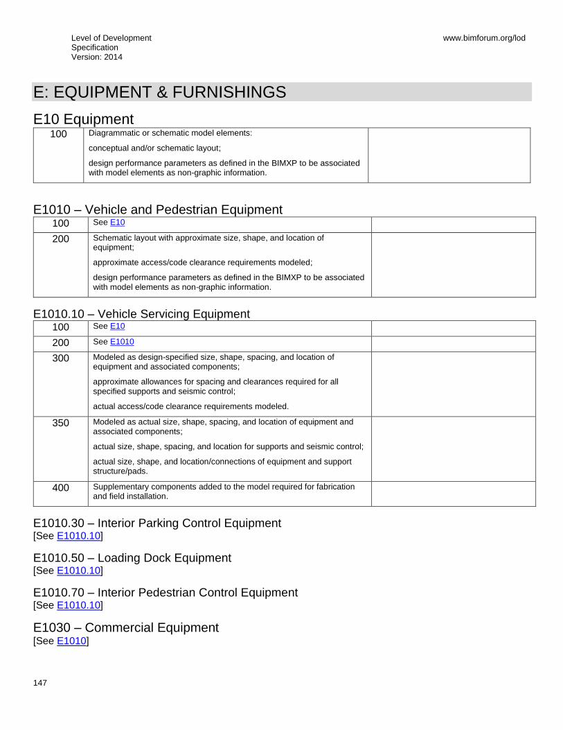
Level of Development Specification Version: 2014
www.bimforum.org/lod
147
E: EQUIPMENT & FURNISHINGS
E10 Equipment 100 Diagrammatic or schematic model elements:
conceptual and/or schematic layout;
design performance parameters as defined in the BIMXP to be associated with model elements as non-graphic information.
E1010 – Vehicle and Pedestrian Equipment 100 See E10
200 Schematic layout with approximate size, shape, and location of equipment;
approximate access/code clearance requirements modeled;
design performance parameters as defined in the BIMXP to be associated with model elements as non-graphic information.
E1010.10 – Vehicle Servicing Equipment 100 See E10
200 See E1010
300 Modeled as design-specified size, shape, spacing, and location of equipment and associated components;
approximate allowances for spacing and clearances required for all specified supports and seismic control;
actual access/code clearance requirements modeled.
350 Modeled as actual size, shape, spacing, and location of equipment and associated components;
actual size, shape, spacing, and location for supports and seismic control;
actual size, shape, and location/connections of equipment and support structure/pads.
400 Supplementary components added to the model required for fabrication and field installation.
E1010.30 – Interior Parking Control Equipment [See E1010.10]
E1010.50 – Loading Dock Equipment [See E1010.10]
E1010.70 – Interior Pedestrian Control Equipment [See E1010.10]
E1030 – Commercial Equipment [See E1010]

Level of Development Specification Version: 2014
www.bimforum.org/lod
148
E1030.10 – Mercantile and Service Equipment [See E1010.10]
E1030.20 – Vault Equipment [See E1010.10]
E1030.25 – Teller and Service Equipment [See E1010.10]
E1030.30 – Refrigerated Display Equipment [See E1010.10]
E1030.35 – Commercial Laundry and Dry Cleaning Equipment [See E1010.10]
E1030.40 – Maintenance Equipment [See E1010.10]
E1030.50 – Hospitality Equipment [See E1010.10]
E1030.55 – Unit Kitchens [See E1010.10]
E1030.60 – Photographic Processing Equipment [See E1010.10]
E1030.70 – Postal, Packaging and Shipping Equipment [See E1010.10]
E1030.75 – Office Equipment [See E1010.10]
E1030.80 – Foodservice Equipment [See E1010.10]
Level of Development Specification Version: 2014
www.bimforum.org/lod
149
E1040 – Institutional Equipment [See E1010]
E1040.10 – Educational and Scientific Equipment [See E1010.10]
E1040.20 – Healthcare Equipment [See E1010.10]
E1040.40 – Religious Equipment [See E1010.10]
E1040.60 – Security Equipment [See E1010.10]
E1040.70 – Detention Equipment [See E1010.10]
E1060 – Residential Equipment [See E1010]
E1060.10 – Residential Appliances [See E1010.10]
E1060.50 – Residential Stairs [See B1080]
E1060.70 – Residential Ceiling Fans [See E1010.10]
E1070 – Entertainment and Recreational Equipment [See E1010]
E1070.10 – Theater and Stage Equipment [See E1010.10]
E1070.20 – Musical Equipment [See E1010.10]
E1070.50 – Athletic Equipment [See E1010.10]
E1070.60 – Recreational Equipment [See E1010.10]
E1090 – Other Equipment [See E1010]
E1090.10 – Solid Waste Handling Equipment [See E1010.10]

Level of Development Specification Version: 2014
www.bimforum.org/lod
150
E1090.30 – Agricultural Equipment [See E1010.10]
E1090.40 – Horticultural Equipment [See E1010.10]
E1090.60 – Decontamination Equipment [See E1010.10]
E20 Furnishings 100 A schematic model element or symbol that is not distinguishable by type or
material.
Types, layouts, and locations are still flexible.
E2010 – Fixed Furnishings 100 See E20
200 Generic model elements with approximate nominal size.
Placement and quantity remains flexible.
Required non-graphic information associated with model elements includes included with element:
Type of object
E2010.10 – Fixed Art 100 See E20
200 See E2010
300 Modeled types with specific dimensions, locations, and quantities.
350 Include any applicable service or installation clearances.
Include any applicable support or connection points.
400 Supplementary components added to the model required for fabrication and field installation.
E2010.20 – Window Treatments [See E2010.10]
E2010.30 – Casework [See E2010.10]
E2010.70 – Fixed Multiple Seating [See E2010.10]
E2010.90 – Other Fixed Furnishings [See E2010.10]

Level of Development Specification Version: 2014
www.bimforum.org/lod
151
E2050 – Movable Furnishings [See E2010]
E2050.10 – Movable Art [See E2010.10]
E2050.30 – Furniture [See E2010.10]
E2050.40 – Accessories [See E2010.10]
E2050.60 – Movable Multiple Seating [See E2010.10]
E2050.90 – Other Movable Furnishings [See E2010.10]
Level of Development Specification Version: 2014
www.bimforum.org/lod
152
F: SPECIAL CONSTRUCTION & DEMOLITION
F10 Special Construction
F1010 – Integrated Construction [See Fundamental LOD Definitions]
F1020 – Special Structures [See Fundamental LOD Definitions]
F1030 – Special Function Construction [See Fundamental LOD Definitions]
F1050 – Special Facility Components [See Fundamental LOD Definitions]
F1060 – Athletic and Recreational Special Construction [See Fundamental LOD Definitions]
F1080 – Special Instrumentation [See Fundamental LOD Definitions]
F20 Facility Remediation
F2010 – Hazardous Materials Remediation [See Fundamental LOD Definitions]
F30 Demolition
F3010 – Structure Demolition [See Fundamental LOD Definitions]
F3030 – Selective Demolition [See Fundamental LOD Definitions]
F3050 – Structure Moving [See Fundamental LOD Definitions]
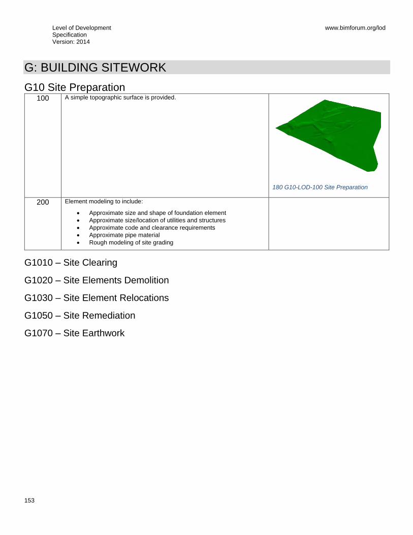
Level of Development Specification Version: 2014
www.bimforum.org/lod
153
G: BUILDING SITEWORK
G10 Site Preparation 100 A simple topographic surface is provided.
180 G10-LOD-100 Site Preparation
200 Element modeling to include:
Approximate size and shape of foundation element
Approximate size/location of utilities and structures
Approximate code and clearance requirements
Approximate pipe material
Rough modeling of site grading
G1010 – Site Clearing
G1020 – Site Elements Demolition
G1030 – Site Element Relocations
G1050 – Site Remediation
G1070 – Site Earthwork
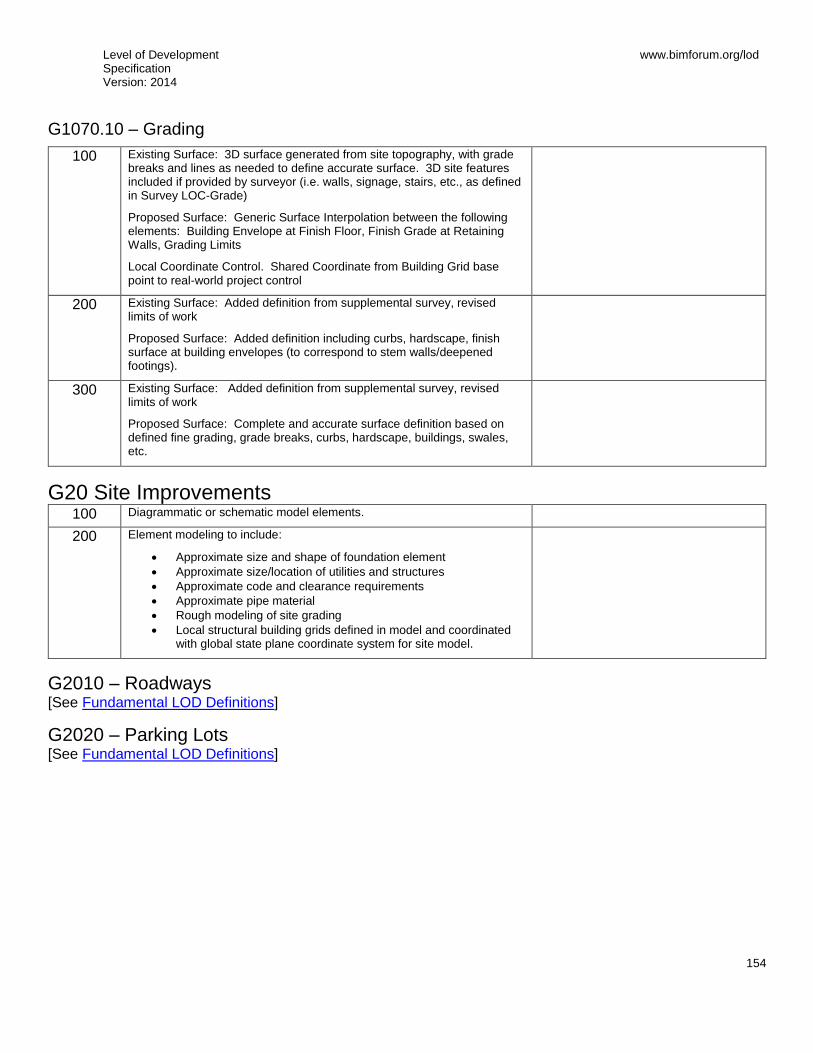
Level of Development Specification Version: 2014
www.bimforum.org/lod
154
G1070.10 – Grading
100 Existing Surface: 3D surface generated from site topography, with grade breaks and lines as needed to define accurate surface. 3D site features included if provided by surveyor (i.e. walls, signage, stairs, etc., as defined in Survey LOC-Grade)
Proposed Surface: Generic Surface Interpolation between the following elements: Building Envelope at Finish Floor, Finish Grade at Retaining Walls, Grading Limits
Local Coordinate Control. Shared Coordinate from Building Grid base point to real-world project control
200 Existing Surface: Added definition from supplemental survey, revised limits of work
Proposed Surface: Added definition including curbs, hardscape, finish surface at building envelopes (to correspond to stem walls/deepened footings).
300 Existing Surface: Added definition from supplemental survey, revised limits of work
Proposed Surface: Complete and accurate surface definition based on defined fine grading, grade breaks, curbs, hardscape, buildings, swales, etc.
G20 Site Improvements 100 Diagrammatic or schematic model elements.
200 Element modeling to include:
Approximate size and shape of foundation element
Approximate size/location of utilities and structures
Approximate code and clearance requirements
Approximate pipe material
Rough modeling of site grading
Local structural building grids defined in model and coordinated with global state plane coordinate system for site model.
G2010 – Roadways [See Fundamental LOD Definitions]
G2020 – Parking Lots [See Fundamental LOD Definitions]

Level of Development Specification Version: 2014
www.bimforum.org/lod
155
G2020.10 – Parking Lot Pavement 100 See G20 200 See G20 300 Specific thickness of pavement and substrate modeled.
All drainage slopes modeled.
350 Openings for drains and other services modeled.
G2020.20 – Parking Lot Curbs and Gutters 100 See G20
200 See G20
300 Full extents of curbs and gutters (above and below grade) are modeled.
350 Element modeling to include:
Reinforcing
Pour stops
Expansion joints
G2020.40 – Parking Lot Appurtenances Includes traffic signals, signage, striping.
[See Fundamental LOD Definitions]
G2030 – Pedestrian Plazas and Walkways
G2040 – Airfields
G2050 – Athletic, Recreational, and Playfield Areas
G2060 – Site Development [See Fundamental LOD Definitions]
G2080 – Landscaping [See Fundamental LOD Definitions]
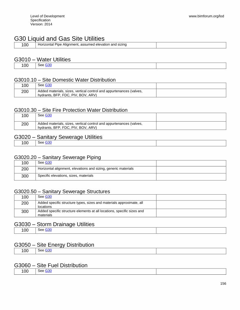
Level of Development Specification Version: 2014
www.bimforum.org/lod
156
G30 Liquid and Gas Site Utilities 100 Horizontal Pipe Alignment, assumed elevation and sizing
G3010 – Water Utilities 100 See G30
G3010.10 – Site Domestic Water Distribution 100 See G30 200 Added materials, sizes, vertical control and appurtenances (valves,
hydrants, BFP, FDC, PIV, BOV, ARV)
G3010.30 – Site Fire Protection Water Distribution 100 See G30
200 Added materials, sizes, vertical control and appurtenances (valves, hydrants, BFP, FDC, PIV, BOV, ARV)
G3020 – Sanitary Sewerage Utilities 100 See G30
G3020.20 – Sanitary Sewerage Piping 100 See G30 200 Horizontal alignment, elevations and sizing, generic materials
300 Specific elevations, sizes, materials
G3020.50 – Sanitary Sewerage Structures 100 See G30 200 Added specific structure types, sizes and materials approximate, all
locations
300 Added specific structure elements at all locations, specific sizes and materials
G3030 – Storm Drainage Utilities 100 See G30
G3050 – Site Energy Distribution 100 See G30
G3060 – Site Fuel Distribution 100 See G30

Level of Development Specification Version: 2014
www.bimforum.org/lod
157
G3090 – Liquid and Gas Site Utilities Supplementary Components These components are typically modeled as part of other assemblies listed in the tables above. Do not assign this Uniformat classification unless a supplementary component is modeled independently of another assembly.
G40 Electrical Site Improvements 100 Diagrammatic or schematic model elements:
conceptual and/or schematic layout;
design performance parameters as defined in the BIMXP to be associated with model elements as non-graphic information.
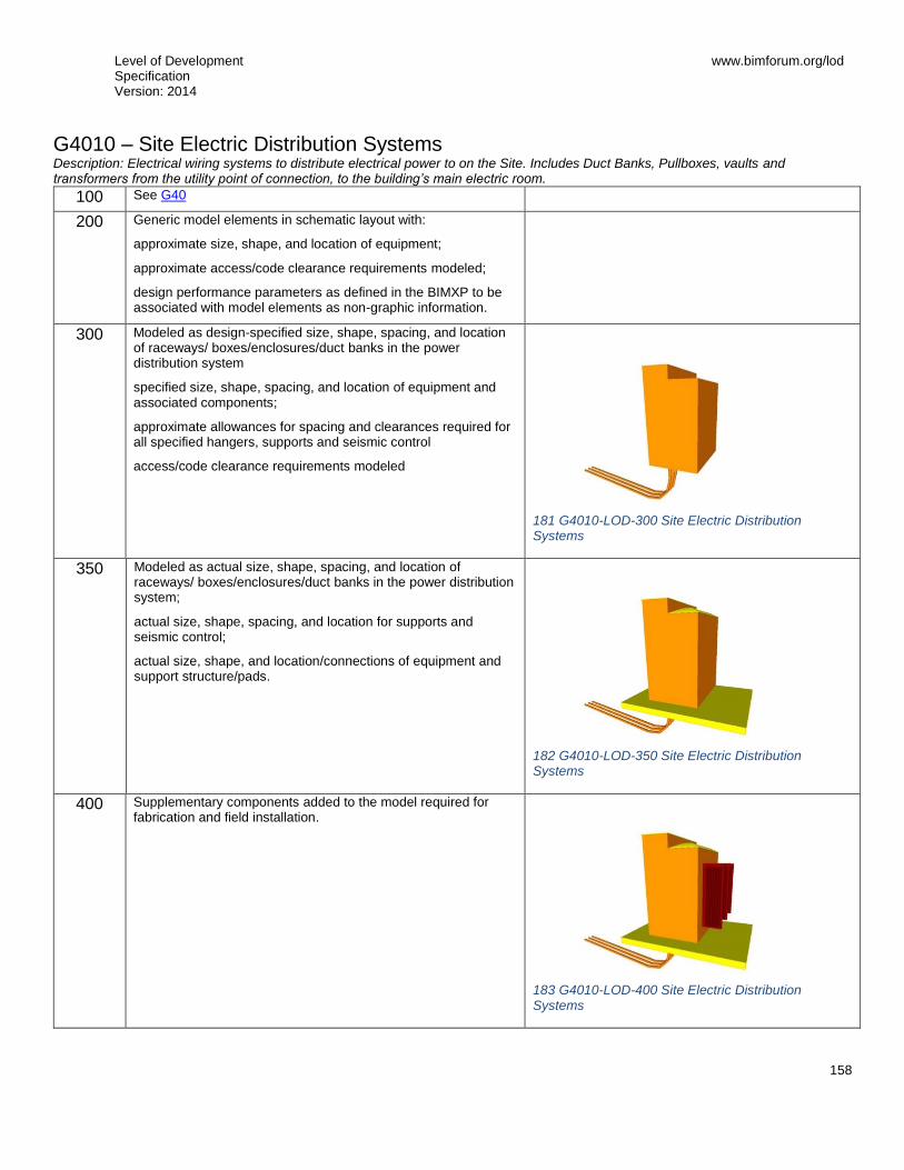
Level of Development Specification Version: 2014
www.bimforum.org/lod
158
G4010 – Site Electric Distribution Systems Description: Electrical wiring systems to distribute electrical power to on the Site. Includes Duct Banks, Pullboxes, vaults and transformers from the utility point of connection, to the building’s main electric room.
100 See G40
200 Generic model elements in schematic layout with:
approximate size, shape, and location of equipment;
approximate access/code clearance requirements modeled;
design performance parameters as defined in the BIMXP to be associated with model elements as non-graphic information.
300 Modeled as design-specified size, shape, spacing, and location of raceways/ boxes/enclosures/duct banks in the power distribution system
specified size, shape, spacing, and location of equipment and associated components;
approximate allowances for spacing and clearances required for all specified hangers, supports and seismic control
access/code clearance requirements modeled
181 G4010-LOD-300 Site Electric Distribution Systems
350 Modeled as actual size, shape, spacing, and location of raceways/ boxes/enclosures/duct banks in the power distribution system;
actual size, shape, spacing, and location for supports and seismic control;
actual size, shape, and location/connections of equipment and support structure/pads.
182 G4010-LOD-350 Site Electric Distribution Systems
400 Supplementary components added to the model required for fabrication and field installation.
183 G4010-LOD-400 Site Electric Distribution Systems

Level of Development Specification Version: 2014
www.bimforum.org/lod
159
G4050 – Site Lighting Description: Luminaires, lighting equipment, ballasts, and accessories. Includes fluorescent, high intensity discharge, incandescent, mercury vapor, neon, and sodium vapor lighting. Includes Pole Mount, Building Mount and on-grade fixtures for exterior lighting.
100 See G40
200 Generic elements in schematic layout with:
approximate size, shape, and location of equipment;
approximate access/code clearance requirements modeled;
design performance parameters as defined in the BIMXP to be associated with model elements as non-graphic information.
300 Modeled as design-specified size, shape, spacing, and location of lighting fixtures;
approximate allowances for spacing and clearances required for all specified hangers, supports and seismic control;
required pole bases and footing elements;
access/code clearance requirements modeled.
350 Modeled as actual size, shape, spacing, and location of lighting fixtures;
actual size, shape, spacing, and location for supports and seismic control;
actual size, shape, and location/connections of equipment and support structure/pads.
400 Supplementary components added to the model required for fabrication and field installation.

Level of Development Specification Version: 2014
www.bimforum.org/lod
160
G50 Site Communications 100 Diagrammatic or schematic model elements:
conceptual and/or schematic layout;
design performance parameters as defined in the BIMXP to be associated with model elements as non-graphic information.
G5010 – Site Communications Systems Description: Conduit Systems for routing of Communication trunk systems.
100 See G50
200 Generic elements in a schematic layout with:
approximate size, shape, and location of equipment;
approximate access/code clearance requirements modeled;
design performance parameters as defined in the BIMXP to be associated with model elements as non-graphic information.
300 Modeled as design-specified size, shape, spacing, and location of raceways, boxes, and enclosures in the power distribution system;
size, shape, spacing, and location of equipment and associated components;
approximate allowances for spacing and clearances required for all specified hangers, supports and seismic control;
access/code clearance requirements modeled.
350 Modeled as actual size, shape, spacing, and location of raceways, boxes, and enclosures in the power distribution system;
size, shape, spacing, and location for supports and seismic control;
size, shape, location, and connections of equipment and support structure or pads;
floor and wall penetrations are modeled.
400 Supplementary components added to the model required for fabrication and field installation.
G90 Miscellaneous Site Construction
G9010 – Tunnels [See Fundamental LOD Definitions]

Level of Development Specification Version: 2014
www.bimforum.org/lod
161
Graphics Index 1 A1010.10-LOD-200 Wall Foundation .................................................................................................................................................... 14 2 A1010.10-LOD-300 Wall Foundation .................................................................................................................................................... 14 3 A1010.10-LOD-350 Wall Foundations (Shallow Foundations) .............................................................................................................. 15 4 A1010.30-LOD-300 Column Foundations (Deep Foundations) ............................................................................................................. 16 5 A1010.30-LOD-350 Column Foundations ............................................................................................................................................. 16 6 A1010.30-LOD-400 Column Foundations ............................................................................................................................................. 17 7 A1020.80-LOD-200 Grade Beams ........................................................................................................................................................ 19 8 A1020.80-LOD-300 Grade Beams ........................................................................................................................................................ 19 9 A1020.80-LOD-350 Grade Beams ........................................................................................................................................................ 20 10 A40-LOD-200 Slabs-on-Grade ............................................................................................................................................................ 22 11 A4010-LOD-300 Standard Slabs-on-Grade ......................................................................................................................................... 22 12 A4010-LOD-350 Standard Slabs-on-Grade ......................................................................................................................................... 22 13 A4020-LOD-300 Structural Slabs-on-Grade ........................................................................................................................................ 24 14 A4020-LOD-350 Structural Slabs-on-Grade ........................................................................................................................................ 24 15 B1010.10-LOD-100 Floor Structural Frame (Steel Framing Columns) ................................................................................................ 28 16 B1010.10-LOD-200 Floor Structural Frame (Steel Framing Columns) ................................................................................................ 28 17 B1010.10-LOD-300 Floor Structural Frame (Steel Framing Columns) ................................................................................................ 28 18 B1010.10-LOD-350 Floor Structural Frame (Steel Framing Columns) ................................................................................................ 28 19 B1010.10-LOD-400 Floor Structural Frame (Steel Framing Columns) ................................................................................................ 29 20 B1010.10-LOD-300 Floor Structural Frame (Steel Framing Beams) ................................................................................................... 30 21 B1010.10-LOD-350 Floor Structural Frame (Steel Framing Beams) ................................................................................................... 30 22 B1010.10-LOD-400 Floor Structural Frame (Steel Framing Beams) ................................................................................................... 30 23 B1010.100-LOD-300 Floor Structural Frame (Steel Framing Bracing Rods)....................................................................................... 32 24 B1010.100-LOD-350 Floor Structural Frame (Steel Framing Bracing Rods)....................................................................................... 32 25 B1010.100-LOD-400 Floor Structural Frame (Steel Framing Bracing Rods)....................................................................................... 32 26 B1010.10-LOD-200 Floor Structural Frame (Steel Joists) ................................................................................................................... 33 27 B1010.10-LOD-300 Floor Structural Frame (Steel Joists) ................................................................................................................... 33 28 B1010.10-LOD-350 Floor Structural Frame (Steel Joists) ................................................................................................................... 33 29 B1010.10-LOD-400 Floor Structural Frame (Steel Joists) ................................................................................................................... 34 30 B1010.10-LOD-200 Floor Structural Frame (Masonry Framing) ......................................................................................................... 36 31 B1010.10-LOD-300 Floor Structural Frame (Masonry Framing) ......................................................................................................... 36 32 B1010.10-LOD-350 Floor Structural Frame (Masonry Framing) ......................................................................................................... 36 33 B1010.10-LOD-400 Floor Structural Frame (Masonry Framing) ......................................................................................................... 37 34 B1010.10-LOD-200 Floor Structural Frame (Wood Floor Trusses) ..................................................................................................... 38 35 B1010.10-LOD-300 Floor Structural Frame (Wood Floor Trusses) ..................................................................................................... 38 36 B1010.10-LOD-350 Floor Structural Frame (Wood Floor Trusses) ..................................................................................................... 38 37 B1010.10-LOD-400 Floor Structural Frame (Wood Floor Trusses) ..................................................................................................... 39 38 B1080.10-LOD-200 Stair Construction ................................................................................................................................................ 45 39 B1080.10-LOD-300 Stair Construction ................................................................................................................................................ 45 40 B1080.10-LOD-350 Stair Construction ................................................................................................................................................ 46 41 B1080.10-LOD-400 Stair Construction ................................................................................................................................................ 46 42 B1080.50-LOD-200 Stair Railings ....................................................................................................................................................... 47 43 B1080.50-LOD-300 Stair Railings ....................................................................................................................................................... 47 44 B1080.50-LOD-350 Stair Railings ....................................................................................................................................................... 47 45 B1080.50-LOD-400 Stair Railings ................................................................................................................................................... 4847 46 B2010-LOD-200 Exterior Walls ........................................................................................................................................................... 49 47 B2010-LOD-300 Exterior Walls ........................................................................................................................................................... 49 48 B2010-LOD-350 Exterior Walls ........................................................................................................................................................... 49 49 B2010.04-LOD-200 Exterior Wall (Masonry) ....................................................................................................................................... 50 50 B2010.04-LOD-300 Exterior Wall (Masonry) ....................................................................................................................................... 50 51 B2010.04-LOD-350 Exterior Wall (Masonry) ....................................................................................................................................... 50 52 B2010.04-LOD-400 Exterior Wall (Masonry) ....................................................................................................................................... 51 53 B2010.05-LOD-200 Exterior Wall (Cold-Form Metal Framing) ............................................................................................................ 52 54 B2010.05-LOD-300 Exterior Wall (Cold-Form Metal Framing) ............................................................................................................ 52 55 B2010.05-LOD-350 Exterior Wall (Cold-Form Metal Framing) ............................................................................................................ 53 56 B2010.05-LOD-400 Exterior Wall (Cold-Form Metal Framing) ............................................................................................................ 54
Level of Development Specification Version: 2014
www.bimforum.org/lod
162
57 B2010.06-LOD-200 Exterior Wall (Wood) ........................................................................................................................................... 55 58 B2010.06-LOD-300 Exterior Wall (Wood) ........................................................................................................................................... 55 59 B2010.06-LOD-350 Exterior Wall (Wood) ........................................................................................................................................... 56 60 B2010.06-LOD-400 Exterior Wall (Wood) ........................................................................................................................................... 56 61 B2010.10-LOD-100 Exterior Wall Veneer ............................................................................................................................................ 57 62 B2010.10-LOD-200 Exterior Wall Veneer ............................................................................................................................................ 57 63 B2010.10-LOD-300 Exterior Wall Veneer ............................................................................................................................................ 57 64 B2010.10-LOD-350 Exterior Wall Veneer ........................................................................................................................................ 5758 65 B2010.10-LOD-400 Exterior Wall Veneer ............................................................................................................................................ 58 66 B2010.20-LOD-350 Exterior Wall Construction ................................................................................................................................... 59 67 B2010.30-LOD-350 Exterior Wall Interior Skin .................................................................................................................................... 59 68 B2020.30-LOD-200 Exterior Window Wall .......................................................................................................................................... 62 69 B2020.30-LOD-300 Exterior Window Wall .......................................................................................................................................... 62 70 B2020.30-LOD-350 Exterior Window Wall .......................................................................................................................................... 63 71 B2020.30-LOD-400 Exterior Window Wall .......................................................................................................................................... 64 72 C1010.04-LOD-200 Interior Wall (Masonry) ........................................................................................................................................ 73 73 C1010.04-LOD-300 Interior Wall (Masonry) ........................................................................................................................................ 73 74 C1010.04-LOD-350 Interior Wall (Masonry) ........................................................................................................................................ 73 75 C1010.04-LOD-400 Interior Wall (Masonry) ........................................................................................................................................ 74 76 C1010.05-LOD-200 Interior Wall (Cold-Form Metal Framing) ............................................................................................................. 75 77 C1010.05-LOD-300 Interior Wall (Cold-Form Metal Framing) ............................................................................................................. 75 78 C1010.05-LOD-350 Interior Wall (Cold-Form Metal Framing) ............................................................................................................. 76 79 C1010.05-LOD-400 Interior Wall (Cold-Form Metal Framing) ............................................................................................................. 77 80 C1010.06-LOD-200 Interior Wall (Wood) ............................................................................................................................................ 78 81 C1010.06-LOD-300 Interior Wall (Wood) ............................................................................................................................................ 78 82 C1010.06-LOD-350 Interior Wall (Wood) ............................................................................................................................................ 79 83 C1010.06-LOD-400 Interior Wall (Wood) ............................................................................................................................................ 79 84 D1050.70-LOD-100 Pneumatic Tube Systems ................................................................................................................................... 95 85 D1050.70-LOD-200 Pneumatic Tube Systems ................................................................................................................................... 95 86 D1050.70-LOD-300 Pneumatic Tube Systems ................................................................................................................................... 95 87 D1050.70-LOD-350 Pneumatic Tube Systems ................................................................................................................................... 95 88 D1050.70-LOD-400 Pneumatic Tube Systems ................................................................................................................................... 96 89 D2010.10-LOD-200 Facility Potable-Water Storage Tanks ................................................................................................................. 98 90 D2010.10-LOD-300 Facility Potable-Water Storage Tanks ................................................................................................................. 98 91 D2010.10-LOD-350 Facility Potable-Water Storage Tanks ................................................................................................................. 98 92 D2010.10-LOD-400 Facility Potable-Water Storage Tanks ................................................................................................................. 98 93 D2010.20-LOD-100 Domestic Water Equipment ................................................................................................................................. 99 94 D2010.20-LOD-200 Domestic Water Equipment ................................................................................................................................. 99 95 D2010.20-LOD-300 Domestic Water Equipment ................................................................................................................................. 99 96 D2010.20-LOD-350 Domestic Water Equipment ................................................................................................................................. 99 97 D2010.20-LOD-400 Domestic Water Equipment ................................................................................................................................. 99 98 D2010.40-LOD-200 Domestic Water Piping ...................................................................................................................................... 100 99 D2010.40-LOD-300 Domestic Water Piping ...................................................................................................................................... 100 100 D2010.40-LOD-350 Domestic Water Piping .................................................................................................................................... 100 101 D2010.40-LOD-400 Domestic Water Piping .............................................................................................................................. 100100 102 D2010.60-LOD-200 Plumbing Fixtures ............................................................................................................................................ 101 103 D2010.60-LOD-200 Plumbing Fixtures ............................................................................................................................................ 101 104 D2010.60-LOD-350 Plumbing Fixtures ............................................................................................................................................ 101 105 D2010.60-LOD-400 Plumbing Fixtures ...................................................................................................................................... 101101 106 D2020.10-LOD-200 Sanitary Sewerage Equipment ........................................................................................................................ 103 107 D2020.10-LOD-300 Sanitary Sewerage Equipment ........................................................................................................................ 103 108 D2020.10-LOD-350 Sanitary Sewerage Equipment ........................................................................................................................ 103 109 D2020.10-LOD-400 Sanitary Sewerage Equipment ........................................................................................................................ 103 110 D2020.30-LOD-200 Sanitary Sewerage Piping ............................................................................................................................... 104 111 D2020.30-LOD-300 Sanitary Sewerage Piping ............................................................................................................................... 104 112 D2020.30-LOD-350 Sanitary Sewerage Piping ............................................................................................................................... 104 113 D2020.30-LOD-400 Sanitary Sewerage Piping ............................................................................................................................... 104 114 D2030.10-LOD-200 Stormwater Drainage Equipment .................................................................................................................... 106 115 D2030.10-LOD-300 Stormwater Drainage Equipment .................................................................................................................... 106 116 D2030.10-LOD-350 Stormwater Drainage Equipment .................................................................................................................... 106

Level of Development Specification Version: 2014
www.bimforum.org/lod
163
117 D2030.10-LOD-400 Stormwater Drainage Equipment .................................................................................................................... 106 118 D2030.20-LOD-200 Stormwater Drainage Piping ........................................................................................................................... 107 119 D2030.20-LOD-300 Stormwater Drainage Piping ........................................................................................................................... 107 120 D2030.20-LOD-350 Stormwater Drainage Piping ........................................................................................................................... 107 121 D2030.20-LOD-400 Stormwater Drainage Piping ........................................................................................................................... 108 122 D2030.30-LOD-200 Facility Stormwater Drains .............................................................................................................................. 109 123 D2030.30-LOD-300 Facility Stormwater Drains .............................................................................................................................. 109 124 D2030.30-LOD-350 Facility Stormwater Drains .............................................................................................................................. 109 125 D2030.30-LOD-400 Facility Stormwater Drains .............................................................................................................................. 109 126 D2060.10-LOD-200 Compressed-Air Systems ................................................................................................................................ 111 127 D2060.10-LOD-300 Compressed-Air Systems ................................................................................................................................ 111 128 D2060.10-LOD-350 Compressed-Air Systems ................................................................................................................................ 111 129 D2060.10-LOD-400 Compressed-Air Systems ................................................................................................................................ 111 130 D3010.10-200 Fuel Piping ............................................................................................................................................................... 114 131 D3010.10-300 Fuel Piping ............................................................................................................................................................... 114 132 D3010.10-350 Fuel Piping ............................................................................................................................................................... 114 133 D3010.10-400 Fuel Piping ............................................................................................................................................................... 115 134 D3010.50-LOD-200 Fuel Storage Tanks ......................................................................................................................................... 117 135 D3010.50-LOD-300 Fuel Storage Tanks ......................................................................................................................................... 117 136 D3010.50-LOD-350 Fuel Storage Tanks ......................................................................................................................................... 117 137 D3010.50-LOD-400 Fuel Storage Tanks ......................................................................................................................................... 117 138 D3020.10-LOD-200 Heat Generation .............................................................................................................................................. 119 139 D3020.10-LOD-300 Heat Generation .............................................................................................................................................. 119 140 D3020.10-LOD-350 Heat Generation .............................................................................................................................................. 119 141 D3020.10-LOD-400 Heat Generation .............................................................................................................................................. 119 142 D3030.10-LOD-200 Central Cooling ............................................................................................................................................... 122 143 D3030.10-LOD-300 Central Cooling ............................................................................................................................................... 122 144 D3030.10-LOD-350 Central Cooling ............................................................................................................................................... 122 145 D3030.10-LOD-400 Central Cooling ............................................................................................................................................... 122 146 D3030.30-LOD-200 Evaporative Air-Cooling ................................................................................................................................... 123 147 D3030.30-LOD-300 Evaporative Air-Cooling ................................................................................................................................... 123 148 D3030.30-LOD-350 Evaporative Air-Cooling ................................................................................................................................... 123 149 D3030.30-LOD-400 Evaporative Air-Cooling ................................................................................................................................... 123 150 D3050.10-LOD-200 Facility Hydronic Distribution ........................................................................................................................... 125 151 D3050.10-LOD-300 Facility Hydronic Distribution ........................................................................................................................... 125 152 D3050.10-LOD-350 Facility Hydronic Distribution ........................................................................................................................... 125 153 D3050.10-LOD-400 Facility Hydronic Distribution ........................................................................................................................... 126 154 D3060.10-LOD-200 Supply Air ........................................................................................................................................................ 128 155 D3060.10-LOD-300 Supply Air ........................................................................................................................................................ 128 156 D3060.10-LOD-350 Supply Air ........................................................................................................................................................ 128 157 D3060.10-LOD-400 Supply Air ........................................................................................................................................................ 129 158 D3060.30-LOD-200 Exhaust Air ...................................................................................................................................................... 130 159 D3060.30-LOD-300 Exhaust Air ...................................................................................................................................................... 130 160 D3060.30-LOD-350 Exhaust Air ...................................................................................................................................................... 130 161 D3060.30-LOD-400 Exhaust Air ...................................................................................................................................................... 130 162 D4010.10-LOD-200 Water-Based Fire-Suppression ....................................................................................................................... 133 163 D4010.10-LOD-300 Water-Based Fire-Suppression ....................................................................................................................... 133 164 D4010.10-LOD-350 Water-Based Fire-Suppression ....................................................................................................................... 133 165 D4010.10-LOD-400 Water-Based Fire-Suppression ....................................................................................................................... 133 166 D5010.10-LOD-200 Packaged Generator Assemblies .................................................................................................................... 136 167 D5010.10-LOD-300 Packaged Generator Assemblies .................................................................................................................... 136 168 D5010.10-LOD-350 Packaged Generator Assemblies .................................................................................................................... 136 169 D5010.10-LOD-400 Packaged Generator Assemblies .................................................................................................................... 136 170 D5020.10-LOD-300 Electrical Service Entrance ............................................................................................................................. 138 171 D5020.10-LOD-350 Electrical Service Entrance ............................................................................................................................. 138 172 D5020.10-LOD-400 Electrical Service Entrance ............................................................................................................................. 138 173 D5020.30-LOD-300 Power Distribution ........................................................................................................................................... 139 174 D5020.30-LOD-350 Power Distribution ........................................................................................................................................... 139 175 D5020.30-LOD-400 Power Distribution ........................................................................................................................................... 139 176 D5030.10-LOD-300 Branch Wiring System ..................................................................................................................................... 141 177 D5030.10-LOD-350 Branch Wiring System ..................................................................................................................................... 141
Level of Development Specification Version: 2014
www.bimforum.org/lod
164
178 D5040.50-LOD-300 Lighting Fixtures .............................................................................................................................................. 143 179 D5040.50-LOD-350 Lighting Fixtures .............................................................................................................................................. 143 180 G10-LOD-100 Site Preparation ....................................................................................................................................................... 153 181 G4010-LOD-300 Site Electric Distribution Systems......................................................................................................................... 158 182 G4010-LOD-350 Site Electric Distribution Systems......................................................................................................................... 158 183 G4010-LOD-400 Site Electric Distribution Systems......................................................................................................................... 158