
DATA COMMUNICATION & NETWORKING B.E (E.C) SEM VIII · 2017-12-22 · cable is typically orange;...
52
Government Engineering College Dahod Laboratory Manual For DATA COMMUNICATION & NETWORKING B.E (E.C) SEM VIII Prepared By: Parth Patel. Asst. Prof. Department of Electronics & Communication
Transcript of DATA COMMUNICATION & NETWORKING B.E (E.C) SEM VIII · 2017-12-22 · cable is typically orange;...

Government Engineering College Dahod
Laboratory Manual
For
DATA COMMUNICATION &
NETWORKING
B.E (E.C)
SEM VIII
Prepared By:
Parth Patel. Asst. Prof.
Department of Electronics & Communication
LIST OF EXPEREMENTS
1. To Study about different physical equipment used for networking.
2. To Study OSI reference model and TCP/IP reference model.
3. To Connect two pc using peer to peer communication.
4. To Study & Network topologies with advantages & disadvantages.
5. Write a program to generate CRC code for checking error.
6. To Plot Efficiency of pure Aloha and slotted ALOHA in MATLAB.
7. To Plot Channel Efficiency for Ethernet in MATLAB.
8. To Study RSA – Public Key Cryptography Algorithm.
9. To Study the Network Simulator (NS2).
10. To Implement wired network topology and wireless network topology
in ns2.
11. To Implement UDP protocol and study performance using network
simulator (ns2).
12. To Connect the computers in Local Area Network.
GECD, E & C Dept. Data Communication & Networking
1
Date: ___________
EXPERIMENT No: 1
AIM: To study about different physical equipment used for networking.
What is Computer Network? Computer network means an interconnected collection of autonomous computers. Two computes
said to be connected if they are able to exchange information. The connection needs not to be via
a copper wire, fiber optics, microwares and communication satellite can also be used.
By requiring the computer to be autonomous, we wish to include from our definition system in
which there is a clear master/slave relation. If one computer can forcibly start, stop or control
another one, the computers are not autonomous. A system with one control unit and many slaves
is not a network, nor is a large computer with remote printers.
Advantages of Computer network:
Resource Sharing
High Reliability
Saving Money
SERVER
Concept of a server is based on one or more personal computers to perform specific tasks for a
number of other PCs. The most common function is disk, file and print servers.
A Disk Server provides low-level support and performs basic read/write operation to disk
sectors.
A File Sever is a higher-level support mechanism, performing such function as lockout and
dynamic allocation of space on disk.
In a star layout the server is the principal connection point. All nodes, including the server, are
connected to a hub. This enables the server to house and administer software, fie sharing, file
saving and to allocate printers or other peripherals.
In a bus layout, the server acts like arbitrator, each node talks to the server when requesting
information. The server then locates the information on one of the connected clients and sends it
to the requesting client.
Servers in any network can be an ordinary node but having more capabilities pf handling the data
and having more speed. There are special servers also available in the market like HPLC2000,
which can connect 18 * 3 HDD and having 512 MB of RAM.

GECD, E & C Dept. Data Communication & Networking
2
WORKSTATION
A node or stand-alone PC that is connected with network is called Workstation. A workstation is
generally a Client.
NIC (Network Interface Card):
The network Interface Card (NIC) is the interface between the PC and physical network
connection. In Ethernet systems, the NIC connection to a segment of coaxial or UTP cable (fiber
NICs are available but not very common yet). As with any other type of adapter card NICs come
in ISA, PCMCIA, and PCI bus varieties.
The NIC is responsible for the operation that tasks place in the physical layer of the OSI model.
It is only concerned with sending and receiving) 0s and 1s, using the IEEE 802.3 Ethernet
standard.
In windows, the NIC card is identified in the network property; to use protocol with NIC you
must bind the protocol to the adapter car. This is typical done automatically when the protocol is
added.
All the NICs are manufactured with a unique 4-bit Mac address using the WINIPCFG utility
(from the run menu). IT is also called as Network Adapter Card.
Function of NIC:
Data Transfer
Data Buffering
Frame Construction
Media Access Control
Parallel/Serial Conversion
Data Encoding/Decoding
Data Transmission/Reception

GECD, E & C Dept. Data Communication & Networking
3
CABLES
To transmit the data the medium must exist, usually in the form of cables or wireless media.
Here are some most commonly used cable types.
1. Thick Coaxial Cables (thick net) (RG-11)
Thick coaxial cables or thick wire is known as the Ethernet standard RG-11. This cable is
mostly used as backbone cable, distributing Ethernet signal through out a building, an
office complex or other large installation. It is used in 10base5 Ethernet standard. RG-11
is thicker and more study than RG-58 coax.
The length may be up to 500 maters with a max of five segments connected by repeaters.
This gives a total distance of 2500 meters. This is called a network diameter. RG-11
cable is typically orange; with black rings around the cable every 2.5-meter to allow taps
into the cable.
2. Thin coaxial cables (thin net) (RG-58)
RG-58 is typically used for wiring laboratories and offices, or another small group of
computers. The maximum length of thin wire Ethernet segment is 185 meters, Which is
due to the nature of the CSMA/CD method of operation, the cable attenuation, and the
speed at which signals propagate inside the coax. The length is limited to guarantee that
collision is detected when machines that are apart transmit at the same time. BNC
connectors are used to terminate each end of the cable.
When many machines are connected to the same Ethernet segment, a daisy chain
approach is used. The BNC connectors allow the network interface card to the next
machine. The machine each end of the cable must use a terminating resistor to eliminate
collision-causing reflection in the cable.
3. Twisted pair cables
Twisted pair is probably the most widely used cabling system in Ethernet in networks.
Two copper wires twist around each other to form the twisted pair cable. Depending on
category several insulated wire strands can reside in the cable.
Twisted pair is available in two basic types
Unshielded Twisted Pair (UTP)
Shielded Twisted Pair (STP)

GECD, E & C Dept. Data Communication & Networking
4
Unshielded Twisted Pair
Mostly the UTP is used. A twisted pair segment can’t exceed 100 meters. This limitation
is the only drawback to twisted pair. Twisted pair is used for 10/100 based Ethernet
networks.
UTP cables are wired as straight through or crossover cables. Straight through cables
typically connect the computer’s networks interface can’t to be a port on the hub.
Crossover cables are used for NIC to communication and for hub-to-hub connections
when no crossover port is available.
UTP categories
Category Descriptor
1 Used for voice for data.
2 Contains four twisted pair and a data transmission up to 4 Mbps. Used for
some token ring network.
3 Contains four twisted pair and a data transmission up to 10 Mbps. Used for
some token ring network.
4 Contains four twisted pair and a data transmission up to 16 Mbps. Used for
some token ring network.
5 Contains four twisted pair and a data transmission up to 100 Mbps. Used
for some token ring network.
Category-5 cables can be purchased or crimped as either straight through or crossed. A
category-5 cable has 8 thin. Colors coded wires inside that run from one end of the cable
to the other. Ethernet networks for communication use only wires 1, 2, 3 and to be
connected in both jacks.
Straight through cables are used for connecting to a hub. Crossed cables are used for
connecting a hub to another hub (there is an exception: some hubs are a built in up link
port that is crossed internally, which allows a you to uplink hubs with a straight cable
instead.)
In a straight through cable wires 1,2,3 and 6 at the other end. In a crossed cable, one order
of the wires change from one end to the other wire 1 becomes 3 and 2 becomes 6.
GECD, E & C Dept. Data Communication & Networking
5
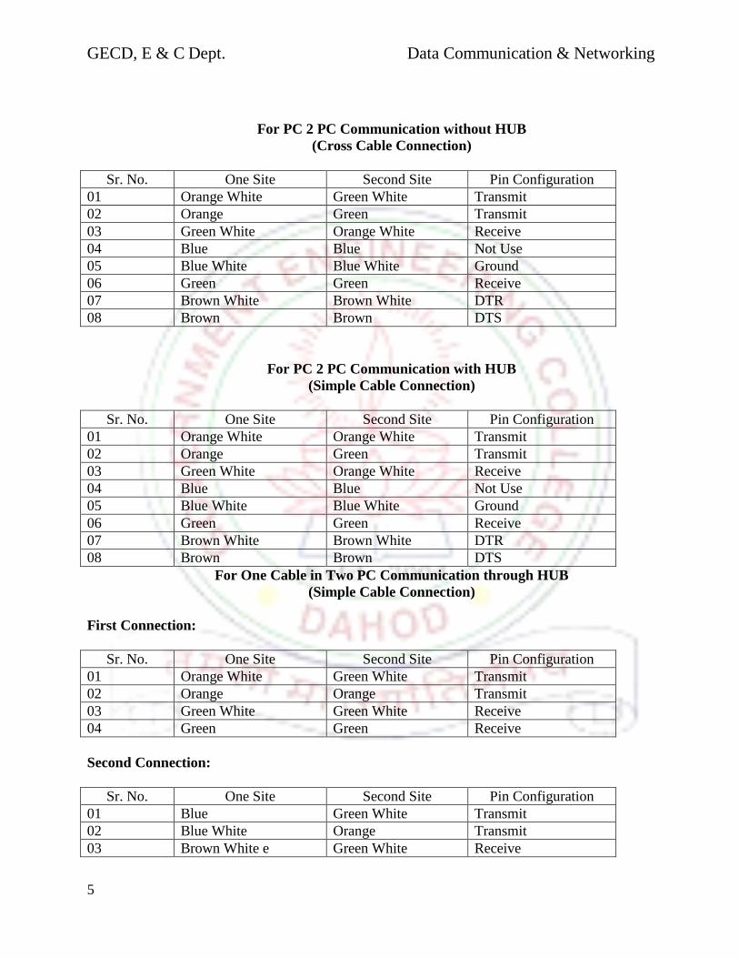
For PC 2 PC Communication without HUB
(Cross Cable Connection)
Sr. No. One Site Second Site Pin Configuration
01 Orange White Green White Transmit
02 Orange Green Transmit
03 Green White Orange White Receive
04 Blue Blue Not Use
05 Blue White Blue White Ground
06 Green Green Receive
07 Brown White Brown White DTR
08 Brown Brown DTS
For PC 2 PC Communication with HUB
(Simple Cable Connection)
Sr. No. One Site Second Site Pin Configuration
01 Orange White Orange White Transmit
02 Orange Green Transmit
03 Green White Orange White Receive
04 Blue Blue Not Use
05 Blue White Blue White Ground
06 Green Green Receive
07 Brown White Brown White DTR
08 Brown Brown DTS
For One Cable in Two PC Communication through HUB
(Simple Cable Connection)
First Connection:
Sr. No. One Site Second Site Pin Configuration
01 Orange White Green White Transmit
02 Orange Orange Transmit
03 Green White Green White Receive
04 Green Green Receive
Second Connection:
Sr. No. One Site Second Site Pin Configuration
01 Blue Green White Transmit
02 Blue White Orange Transmit
03 Brown White e Green White Receive

GECD, E & C Dept. Data Communication & Networking
6
04 Brown Green Receive
Shielded Twisted Pair
It is 150Ω cable containing additional shielding that protects signals against
electromagnetic Interference (EMI) produced by electric motors power lines etc. It is
primarily used in Token Ring Network & where UTP cable would provide insufficient
protection against interface.
Wires within cables are encased in a metallic sheath that is conductive as copper in wires.
This sheath when properly grounded converts it ambient noise into current, like antenna.
This current is carried to wires within where it creates an equal and opposite current
flowing in twisted pair thus getting cancelled and no noise signal is resulted.
4. Fiber Optic.
Fiber Optic relies on pulsed as light to carry information. Two types of plastic or glass
with different physical propertied are used (the inner core and the outer cladding) to
allow a beam of light to reflect off the boundary between the core and cladding. Some
fiber optic cables allow many different paths other allow one single mode. They are
called multimode and single mode fibers. A popular multimode fiber has core/cladding
dimensions of 62.5/125 nanometers.
REPEATER
A Repeater is a purely electrical device that extends maximum distance a LAN cable can span by
Amplifying signals passing through it. A Repeater connects two segments and broadcasts
packets between them. Since signal loss is a factor in the maximum length of a segment, a
Repeater is used to amplify the signal and extend the usable length. A common Ethernet rule is
that no more than four repeaters may be used to join segments together. This is a physical
limitation designed to keep collision detection working properly. Repeaters operate at layer 1
(Physical layer) of the OSI model.
BRIDGES
This networks bridge provides an inexpensive and easy way to connect network segments. A
bridge provides Amplification function of a repeater plus, ability to select filter packets based on
their addresses. When network grows in size, it is often necessary to partition it in to smaller
group of nodes to help isolate traffic and improve performance. One way t do this is to use
bridge, the operation of it is to keep one segment traffic to that side and other to other side will
cross the bridge, The bridge learns which packets should cross it as it is used.
ROUTERS
A router is a device that connects two LANs together to form an inter-network. A router is the
basic building block of the Internet. Each router connects two or more networks together by
providing an interface for an Ethernet network and ring network to which it is connected. The
router examines each packet of information to detection weather the packet must be translated
form on one network to another network performing a function similar to a bridge. Unlike a

GECD, E & C Dept. Data Communication & Networking
7
ridge, a router can connect network that use different technologies, addressing methods, media
type, frame format and speeds.
A router is a special purpose device designed to interconnect networks. Such that three networks
can be connected using two routers.
Routers maintain routing tables in their memories to store information about the physical
connection on he network; the router examines each packet of data, checks the routing table and
then forwards the packet if necessary. Every other router in the path (between any state
destinations) performs a similar procedure. Note that a router does not maintain any state
information about the packets; it simply moves them along the network. Routers are operated at
layer 3(network) of OSI model.
GATEWAYS
A node on a network that serves as an entrance to another network. In enterprises, the gateway
node often acts as a proxy server and a firewall. The gateway is also associated with both a
switch, which provides the actual path for the packet in and out of the gateway.
It is also known as a computer system located on earth that switches data signals and voice
signals between satellites and terrestrial networks.
A gateway can operate at any layer of the OSI/RM. The hob of a gateway, also called a protocol
converter, is much more complex than that of a router or switch. Typically a gateway must
convert from one protocol stack to another. E.g. a gateway may connect a TCP/IP network to an
IPX./SPX network.
A Circuit Level Gateway function provided by Application level gateway products enables
trusted users on private network to access Internet services with all security of a proxy server.
An Application Level Gateway provide much stricter form of security that packet filters, but they
are designed to regulate access only for a particular application.
TANSCEIVERS
A transceiver converts from one media type to another. For example, a 10base2 coaxial cable
with a fiber optic cable. It is common to use more then one media type an installation, so many
different kinds of transceivers are available.
HUBS
Hubs are also called concentrators; expand one Ethernet connection into many. For example, a
four-port hub connects up to four machines via UTP cables. The hub provides a star connection
for the four ports. Many hubs contains a single BNC connectors as well to connect the hub to
existing 10base2 network wiring, the hub can also be connected via one of its ports. One pot is
desired to operate in either straight through or crossover mode, selected by a switch on the hub.
Hubs that can connect in this fashion are called stackable hubs.
A hub is similar to a repeater, expect it broadcasts data received by any port to all other ports on
the hub. Most hubs contain a small amount of intelligence as well. Examining received packets
and checking them for integrity. If a bad packet arrives or the hub determines that a port is
unreliable. It will shut down the line under the error condition is appears.
The hub also acts like a repeater. Because of its slight delay when processing a packet, the
numbers of hubs that may be connected in a series are limited.
GECD, E & C Dept. Data Communication & Networking
8
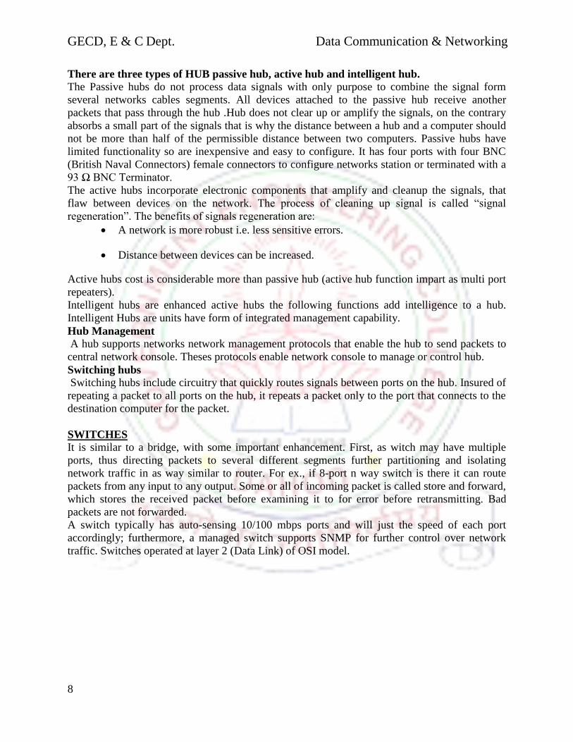
There are three types of HUB passive hub, active hub and intelligent hub.
The Passive hubs do not process data signals with only purpose to combine the signal form
several networks cables segments. All devices attached to the passive hub receive another
packets that pass through the hub .Hub does not clear up or amplify the signals, on the contrary
absorbs a small part of the signals that is why the distance between a hub and a computer should
not be more than half of the permissible distance between two computers. Passive hubs have
limited functionality so are inexpensive and easy to configure. It has four ports with four BNC
(British Naval Connectors) female connectors to configure networks station or terminated with a
93 Ω BNC Terminator.
The active hubs incorporate electronic components that amplify and cleanup the signals, that
flaw between devices on the network. The process of cleaning up signal is called “signal
regeneration”. The benefits of signals regeneration are:
A network is more robust i.e. less sensitive errors.
Distance between devices can be increased.
Active hubs cost is considerable more than passive hub (active hub function impart as multi port
repeaters).
Intelligent hubs are enhanced active hubs the following functions add intelligence to a hub.
Intelligent Hubs are units have form of integrated management capability.
Hub Management
A hub supports networks network management protocols that enable the hub to send packets to
central network console. Theses protocols enable network console to manage or control hub.
Switching hubs
Switching hubs include circuitry that quickly routes signals between ports on the hub. Insured of
repeating a packet to all ports on the hub, it repeats a packet only to the port that connects to the
destination computer for the packet.
SWITCHES
It is similar to a bridge, with some important enhancement. First, as witch may have multiple
ports, thus directing packets to several different segments further partitioning and isolating
network traffic in as way similar to router. For ex., if 8-port n way switch is there it can route
packets from any input to any output. Some or all of incoming packet is called store and forward,
which stores the received packet before examining it to for error before retransmitting. Bad
packets are not forwarded.
A switch typically has auto-sensing 10/100 mbps ports and will just the speed of each port
accordingly; furthermore, a managed switch supports SNMP for further control over network
traffic. Switches operated at layer 2 (Data Link) of OSI model.
GECD, E & C Dept. Data Communication & Networking
9
Date : ___________
EXPERIMENT No: 2
AIM: To Study OSI reference model and TCP/IP reference model
Introduction:
Here, we will discuss two important network architectures - the OSI reference model and the
TCP/IP reference model. Although the protocols associated with the OSI model are rarely used
any more, the model itself is actually quite general and still valid, and the features discussed at
each layer are still very important. The TCP/IP model has the opposite properties: the model
itself is not of much use but the protocols are widely used.
OSI reference model:
Virtually all networks in use today are based in some fashion on the Open Systems
Interconnection (OSI) standard. OSI was developed in 1984 by the International Organization for
Standardization (ISO), a global federation of national standards organizations representing
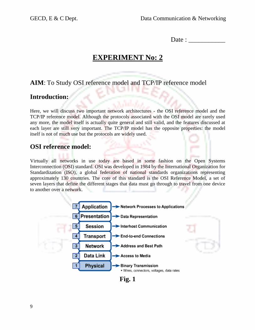
approximately 130 countries. The core of this standard is the OSI Reference Model, a set of
seven layers that define the different stages that data must go through to travel from one device
to another over a network.
Fig. 1

GECD, E & C Dept. Data Communication & Networking
10
The principles that were applied to arrive at the seven layers can be briefly summarized as
follows:
1. A layer should be created where a different abstraction is needed.
2. Each layer should perform a well-defined function.
3. The function of each layer should be chosen with an eye toward defining
internationally standardized protocols.
4. The layer boundaries should be chosen to minimize the information flow across the
interfaces.
5. The number of layers should be large enough that distinct functions need not be
thrown together in the same layer out of necessity and small enough that the
architecture does not become unwieldy.
The layers are as follows:
Layer 1: Physical - This is the level of the actual hardware. It defines the physical
characteristics of the network such as connections, voltage levels and timing.
Layer 2: Data - In this layer, the appropriate physical protocol is assigned to the data.
Also, the type of network and the packet sequencing is defined. The main task of the data
link layer is to transform a raw transmission facility into a line that appears free of
undetected transmission errors to the network layer. It accomplishes this task by having
the sender break up the input data into data frames (typically a few hundred or a few
thousand bytes) and transmits the frames sequentially. If the service is reliable, the
receiver confirms correct receipt of each frame by sending back an acknowledgement
frame.
Layer 3: Network - The way that the data will be sent to the recipient device is
determined in this layer. Logical protocols, routing and addressing are handled here. The
network layer controls the operation of the subnet. A key design issue is determining how
packets are routed from source to destination. Routes can be based on static tables that
are ''wired into'' the network and rarely changed. They can also be determined at the start
of each conversation, for example, a terminal session (e.g., a login to a remote machine).
Finally, they can be highly dynamic, being determined anew for each packet, to reflect
the current network load.
Layer 4: Transport - This layer maintains flow control of data and provides for error
checking and recovery of data between the devices. Flow control means that the
Transport layer looks to see if data is coming from more than one application and
integrates each application's data into a single stream for the physical network.
Layer 5: Session - Layer 5 establishes, maintains and ends communication with the
receiving device. The session layer allows users on different machines to establish
sessions between them. Sessions offer various services, including dialog control (keeping
track of whose turn it is to transmit), token management (preventing two parties from
attempting the same critical operation at the same time), and synchronization (check
GECD, E & C Dept. Data Communication & Networking
11
pointing long transmissions to allow them to continue from where they were after a
crash).
Layer 6: Presentation - Layer 6 takes the data provided by the Application layer and
converts it into a standard format that the other layers can understand. Unlike lower
layers, which are mostly concerned with moving bits around, the presentation layer is
concerned with the syntax and semantics of the information transmitted. In order to make
it possible for computers with different data representations to communicate, the data
structures to be exchanged can be defined in an abstract way, along with a standard
encoding to be used ''on the wire.'' The presentation layer manages these abstract data
structures and allows higher-level data structures (e.g., banking records), to be defined
and exchanged.
Layer 7: Application - This is the layer that actually interacts with the operating
system or application whenever the user chooses to transfer files, read messages or
performs other network-related activities. The application layer contains a variety of
protocols that are commonly needed by users. One widely-used application protocol is
HTTP (Hypertext Transfer Protocol), which is the basis for the World Wide Web. When
a browser wants a Web page, it sends the name of the page it wants to the server using
HTTP. The server then sends the page back. Other application protocols are used for file
transfer, electronic mail, and network news.
TCP/IP Reference Model:
The ARPANET was a research network sponsored by the DoD (U.S. Department of
Defense). It connected hundreds of universities and government installations, using
leased telephone lines. When satellite and radio networks were added later, the existing
protocols had trouble interworking with them, so new reference architecture was needed.
Thus, the ability to connect multiple networks in a seamless way was one of the major
design goals from the very beginning. This architecture later became known as the
TCP/IP Reference Model, after its two primary protocols.
Fig. 2

GECD, E & C Dept. Data Communication & Networking
12
The Internet Layer: This layer is the linchpin that holds the whole architecture
together. Its job is to permit hosts to inject packets into any network and have them travel
independently to the destination (potentially on a different network). They may even
arrive in a different order than they were sent, in which case it is the job of higher layers
to rearrange them, if in-order delivery is desired.
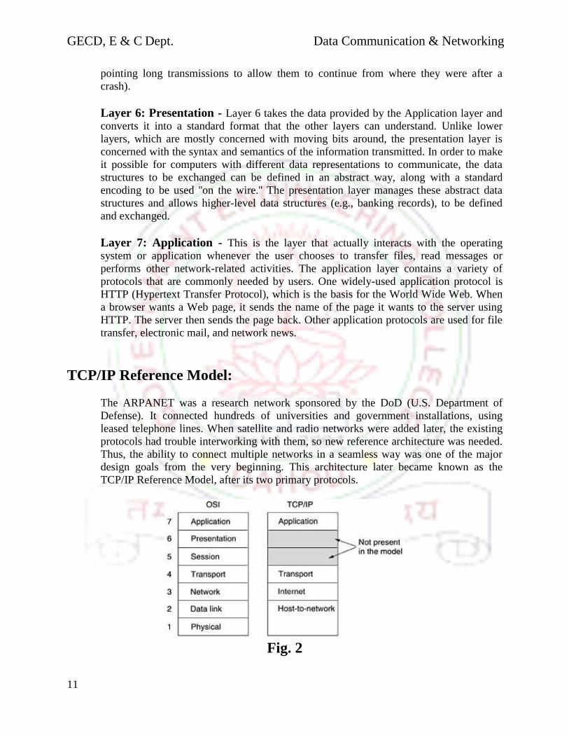
The internet layer defines an official packet format and protocol called IP (Internet
Protocol). The job of the internet layer is to deliver IP packets where they are supposed to
go. Packet routing is clearly the major issue here, as is avoiding congestion. For these
reasons, it is reasonable to say that the TCP/IP internet layer is similar in functionality to
the OSI network layer. Figure 2 shows this correspondence.
The Transport Layer: The layer above the internet layer in the TCP/IP model is now
usually called the transport layer. Two end-to-end transport protocols have been defined
here. The first one, TCP (Transmission Control Protocol), is a reliable connection-
oriented protocol that allows a byte stream originating on one machine to be delivered
without error on any other machine in the internet. TCP also handles flow control to
make sure a fast sender cannot swamp a slow receiver with more messages than it can
handle.
The second protocol in this layer, UDP (User Datagram Protocol), is an unreliable,
connectionless protocol for applications that do not want TCP's sequencing or flow
control and wish to provide their own. It is also widely used for one-shot, client-server-
type request-reply queries and applications in which prompt delivery is more important
than accurate delivery, such as transmitting speech or video. The relation of IP, TCP, and
UDP is shown in Fig.3. Since the model was developed, IP has been implemented on
many other networks.
Figure 3. Protocols and networks in the TCP/IP model initially.
The Application Layer: On top of the transport layer is the application layer. It
contains all the higher-level protocols. The early ones included virtual terminal
(TELNET), file transfer (FTP), and electronic mail (SMTP), as shown in Fig 3.

GECD, E & C Dept. Data Communication & Networking
13
The file transfer protocol provides a way to move data efficiently from one machine to
another. Electronic mail was originally just a kind of file transfer, but later a specialized
protocol (SMTP) was developed for it. Many other protocols have been added to these
over the years: the Domain Name System (DNS) for mapping host names onto their
network addresses, NNTP, the protocol for moving USENET news articles around, and
HTTP, the protocol for fetching pages on the World Wide Web, and many others.
The Host-to-Network Layer: Below the internet layer is a great void. The TCP/IP
reference model does not really say much about what happens here, except to point out
that the host has to connect to the network using some protocol so it can send IP packets
to it. This protocol is not defined and varies from host to host and network to network.
Books and papers about the TCP/IP model rarely discuss it.
A Comparison of the OSI and TCP/IP Reference Models
The OSI and TCP/IP reference models have much in common. Both are based on the concept of
a stack of independent protocols. Also, the functionality of the layers is roughly similar. For
example, in both models the layers up through and including the transport layer are there to
provide an end-to-end, network-independent transport service to processes wishing to
communicate. These layers form the transport provider. Again in both models, the layers above
transport are application-oriented users of the transport service.
Three concepts are central to the OSI model:
1. Services.
2. Interfaces.
3. Protocols.
Probably the biggest contribution of the OSI model is to make the distinction between these three
concepts explicit. Each layer performs some services for the layer above it. The service
definition tells what the layer does, not how entities above it access it or how the layer works. It
defines the layer's semantics.
A layer's interface tells the processes above it how to access it. It specifies what the parameters
are and what results to expect. It, too, says nothing about how the layer works inside.
Finally, the peer protocols used in a layer are the layer's own business. It can use any protocols it
wants to, as long as it gets the job done (i.e., provides the offered services). It can also change
them at will without affecting software in higher layers.
These ideas fit very nicely with modern ideas about object-oriented programming. An object,
like a layer, has a set of methods (operations) that processes outside the object can invoke. The
semantics of these methods define the set of services that the object offers. The methods'
parameters and results form the object's interface. The code internal to the object is its protocol
and is not visible or of any concern outside the object.
GECD, E & C Dept. Data Communication & Networking
14
The TCP/IP model did not originally clearly distinguish between service, interface, and protocol,
although people have tried to retrofit it after the fact to make it more OSI-like. For example, the
only real services offered by the internet layer are SEND IP PACKET and RECEIVE IP
PACKET.
As a consequence, the protocols in the OSI model are better hidden than in the TCP/IP model
and can be replaced relatively easily as the technology changes. Being able to make such
changes is one of the main purposes of having layered protocols in the first place.
The OSI reference model was devised before the corresponding protocols were invented. This
ordering means that the model was not biased toward one particular set of protocols, a fact that
made it quite general. The downside of this ordering is that the designers did not have much
experience with the subject and did not have a good idea of which functionality to put in which
layer.
For example, the data link layer originally dealt only with point-to-point networks. When
broadcast networks came around, a new sub layer had to be hacked into the model. When people
started to build real networks using the OSI model and existing protocols, it was discovered that
these networks did not match the required service specifications (wonder of wonders), so
convergence sub layers had to be grafted onto the model to provide a place for papering over the
differences. Finally, the committee originally expected that each country would have one
network, run by the government and using the OSI protocols, so no thought was given to
internetworking. To make a long story short, things did not turn out that way.
With TCP/IP the reverse was true: the protocols came first, and the model was really just a
description of the existing protocols. There was no problem with the protocols fitting the model.
They fit perfectly. The only trouble was that the model did not fit any other protocol stacks.
Consequently, it was not especially useful for describing other, non-TCP/IP networks.
Turning from philosophical matters to more specific ones, an obvious difference between the two
models is the number of layers: the OSI model has seven layers and the TCP/IP has four layers.
Both have (inter)network, transport, and application layers, but the other layers are different.
Another difference is in the area of connectionless versus connection-oriented communication.
The OSI model supports both connectionless and connection-oriented communication in the
network layer, but only connection-oriented communication in the transport layer, where it
counts (because the transport service is visible to the users). The TCP/IP model has only one
mode in the network layer (connectionless) but supports both modes in the transport layer, giving
the users a choice. This choice is especially important for simple request-response protocols.
GECD, E & C Dept. Data Communication & Networking
15
Date : ___________
EXPERIMENT No: 3
AIM: To Connect two pc using peer to peer communication.
Purpose:-Direct communication between two PCs through network interface card i.e. NIC. It is
also known as LAN card.
Equipments:-
2 PCs with NIC
UTP (unshielded twisted pair) cable
2 RJ-45 connectors
Crimping Tool
Theory:-
The components we have to use in practical are briefly described below.
1. UTP Cable
This is the special type of cable having 4 pair of wires with distinct colors for
identification. Two wires of each pair are twisted such that no. of turns per inch in each
pair is different. This is done to avoid cross talk and Electromagnetic interference (EMI).
There are different types of UTP cables available. These are classified in several
categories according to their ability to transfer/receive the data. Following are some of
these categories.
CAT-3,Transfer rate 10 Mbps
CAT-4,Transfer rate 16 Mbps
CAT-5,Transfer rate 100 Mbps
CAT-1 & 2 are not in use now days due to their very low data transfer capacity.
2. NIC –Network Interface Card
This card enables exchange of data between 2 PCs. It has 8 pins and works in full
duplex mode. So 2 pins acts as transmitter & 2 as receiver. Note that one of the two pins
is for transmitting data and other for acknowledgement .Now as some connectors (RJ-45)
is used with same type of NIC on both sides, we have to connect the transmitter at low
end to the receiver of another and vice versa. Thus , a cross cable is required for this.
3. Cross Cable
To make a straight cable, the tips must be crimped typically the same way at each
end by respecting the twisted pair size.
In general, the code used is:

GECD, E & C Dept. Data Communication & Networking
16
1) orange-white
2) orange
3) green-white
4) Blue
5) blue-white
6) Green
7) brown-white
8) brown
For a crossover cable, swap 1 with 3, and 2 with 6, in the list above. This gives:
1) green-white
2) green
3) orange and white
4) Blue
5) blue-white
6) orange
7) brown-white
8) brown
This cross cable is connected to the 2 NIC ports for peer to peer communication. Crimping
tool is used to insert the cross cable in the RJ-45 connectors and for fine adjustments in it.
General sequence of cable is as follows with copper connectors facing you.
From left side:-
1. White-Red
2. Red
3. White-Blue
4. Blue
5. White-Green
6. Green
7. White-Orange
8. Orange
4. IP Config
This Dos command is used to know the IP configuration of the PC i.e. address & the
subnet mask of the particular PC.
5. Winipcg
This command is used to know the IP configuration of the PC in a graphical form. It
shows the following
IP Address
Subnet Mask
Type of H/W used for communication & it’s address
6. Knowing the name of the PC

GECD, E & C Dept. Data Communication & Networking
17
First go to the properties of network neighborhood where in the identification menu
we can know the name of the PC being used.
7. Giving IP to the PC
For giving IP to a PC first go to the properties of N/W neighborhood and go to the
properties of TCP/IP in configuration menu where you can enter the IP address of your IP
according to the class you are in IP address menu.
8. Accessing Network Resources
For accessing network resources a user has to login with a user name & password of
his choice as his data of identification has to be registered in the network.

GECD, E & C Dept. Data Communication & Networking
18
Date : ___________
EXPERIMENT No: 4
AIM: To Study the following network topologies with advantages &
disadvantages
Types:
1. Bus Topology :
Commonly referred to as a linear bus, all the devices on a bus topology are
connected by one single cable.
Advantages: • Easy to use & inexpensive simple network
• Easy to extend thus allowing long distance traveling of signal
• Requires less cable length than a star topology
Disadvantages: • Becomes slow by heavy network traffic with a lot of computer
• Difficult to troubleshoot & difficult to identify the problem if the entire
network shut down
• Terminator is required at both ends of the backbone cable
• Not meant to be used as a stand alone solution in a large buildin
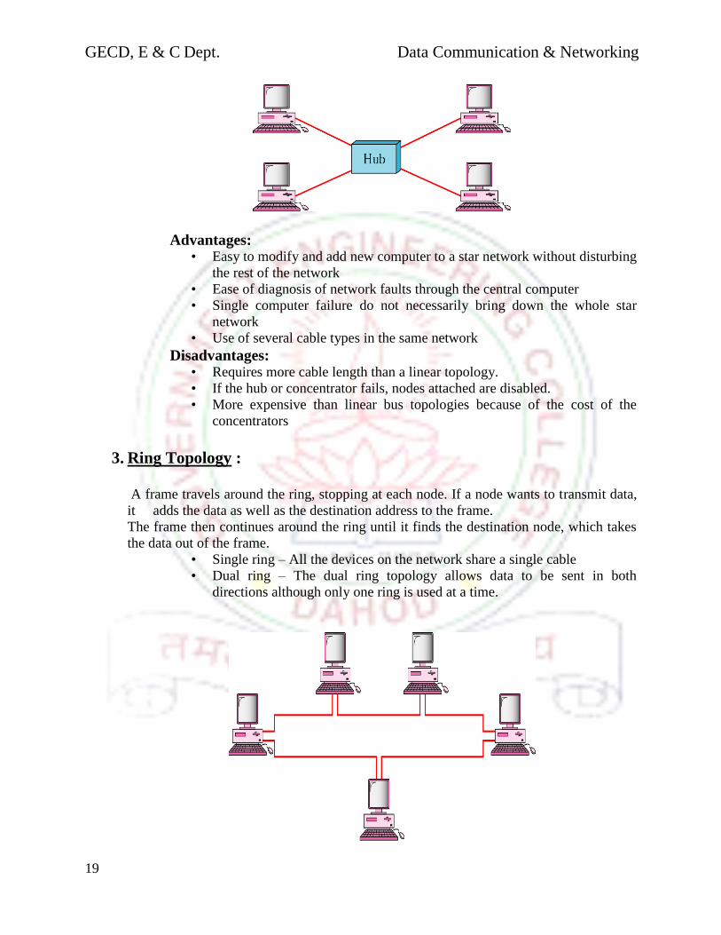
2. Star Topology
The star topology is the most commonly used architecture in Ethernet LANs.
When installed, the star topology resembles spokes in a bicycle wheel.
Larger networks use the extended star topology. When used with network devices
that filter frames or packets, like bridges, switches, and routers, this topology
significantly reduces the traffic on the wires by sending packets only to the wires
of the destination host.
GECD, E & C Dept. Data Communication & Networking
19
Advantages: • Easy to modify and add new computer to a star network without disturbing
the rest of the network
• Ease of diagnosis of network faults through the central computer
• Single computer failure do not necessarily bring down the whole star
network
• Use of several cable types in the same network
Disadvantages: • Requires more cable length than a linear topology.
• If the hub or concentrator fails, nodes attached are disabled.
• More expensive than linear bus topologies because of the cost of the
concentrators
3. Ring Topology :
A frame travels around the ring, stopping at each node. If a node wants to transmit data,
it adds the data as well as the destination address to the frame.
The frame then continues around the ring until it finds the destination node, which takes
the data out of the frame.
• Single ring – All the devices on the network share a single cable
• Dual ring – The dual ring topology allows data to be sent in both
directions although only one ring is used at a time.

GECD, E & C Dept. Data Communication & Networking
20
Advantages: • Every computer is given equal access to the token; no one computer can
monopolize the network
• Fair sharing of the network allows the network to degrade gracefully as
more users are added
Disadvantages: • Failure to one network can affect the whole network
• Difficult to troubleshoot a ring network
• Adding or removing computer disrupts the network
Ring network layout ring network is a topology of computer network where each node is
connected to two other nodes, so as to create a ring. Ring networks tend to be inefficient
when compared to Star networks because data must travel through less number of points
before reaching its destination. For example , if a given ring network has eight computers on
it, to get from computer one to computer four, data must be travel from computer one,
through computers two and three, and to it’s destination at computer four. It could also go
from computer one through eight, seven, six, and five until reaching four, but this method is
slower because it travels through more computers. Ring network also carry the disadvantage
that if one of the nodes in the network breaks then the entire network will break down with it
as it requires a full circle in order to function.
GECD, E & C Dept. Data Communication & Networking
21
Date : ___________
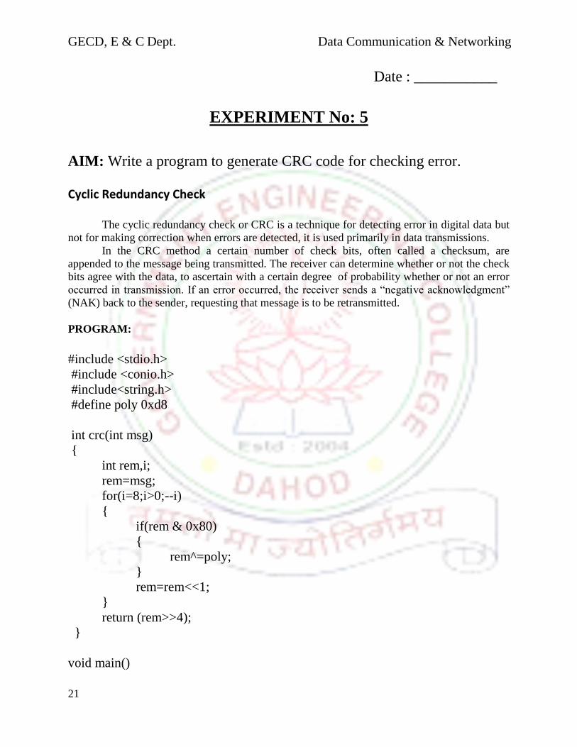
EXPERIMENT No: 5
AIM: Write a program to generate CRC code for checking error. Cyclic Redundancy Check The cyclic redundancy check or CRC is a technique for detecting error in digital data but
not for making correction when errors are detected, it is used primarily in data transmissions.
In the CRC method a certain number of check bits, often called a checksum, are
appended to the message being transmitted. The receiver can determine whether or not the check
bits agree with the data, to ascertain with a certain degree of probability whether or not an error
occurred in transmission. If an error occurred, the receiver sends a “negative acknowledgment”
(NAK) back to the sender, requesting that message is to be retransmitted.
PROGRAM:
#include <stdio.h>
#include <conio.h>
#include<string.h>
#define poly 0xd8
int crc(int msg)
int rem,i;
rem=msg;
for(i=8;i>0;--i)
if(rem & 0x80)
rem^=poly;
rem=rem<<1;
return (rem>>4);
void main()

GECD, E & C Dept. Data Communication & Networking
22
int msg=0xe5,c;
clrscr();
c=crc(msg);
printf("%d",c);
getch();
Here the polynomial is 0xd8 means 11011000 and msg is 0xe5 means 11100101. So at
last we get as an answer means remainder

GECD, E & C Dept. Data Communication & Networking
23
Date : ___________
Date : ___________
EXPERIMENT No: 6
Aim :To Plot Efficiency of pure Aloha and slotted ALOHA in
MATLAB
G=0:0.1:3;
S=G.*exp(-G);
plot(G,S,'b+:');text(1,.38,'MAX THROUGHPUT FOR SLOTTED ALOHA')
xlabel('load offered');
ylabel('throughput');
title('aloha protocol');
hold on;
S1=G.*exp(-2*G);
plot(G,S1,'rd:');
text(0.5,.2,'MAX THROUGHPUT FOR PURE ALOHA')
xlabel ('load offered');
ylabel ('throughput');
title ('aloha protocol');
legend ('Slotted ALOHA','Pure ALOHA','Location','NorthEastOutside')
Result:

GECD, E & C Dept. Data Communication & Networking
24
0 0.5 1 1.5 2 2.5 30
0.05
0.1
0.15
0.2
0.25
0.3
0.35
0.4
MAX THROUGHPUT FOR SLOTTED ALOHA
load offered
thro
ughp
ut
aloha protocol
MAX THROUGHPUT FOR PURE ALOHA
Slotted ALOHA
Pure ALOHA
Date : ___________
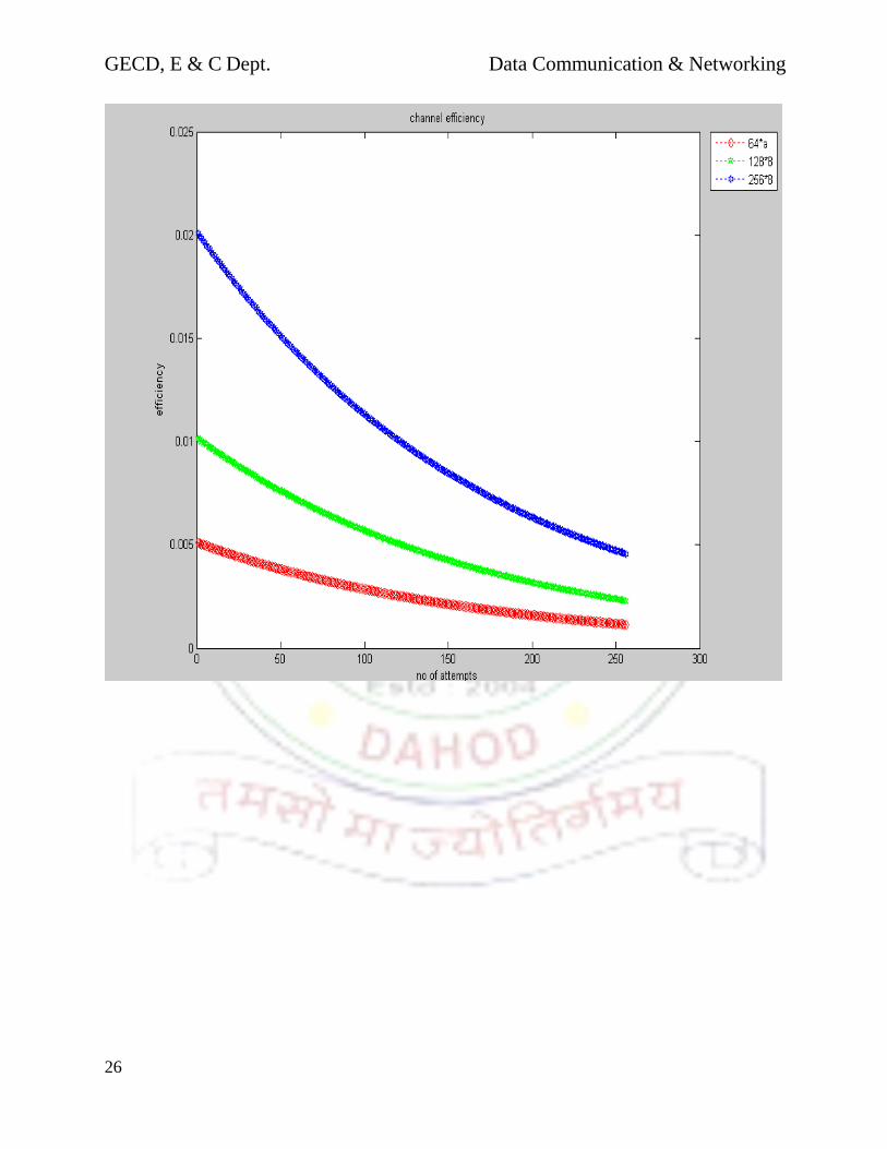
EXPERIMENT No: 7
Aim : To plot Channel Efficiency for Ethernet in MATLAB.
clc;
b=input('enter the b.w.');
l=input('enter the input length');
c=input('enter the input capacity');
k=1:256;
f1=64*8;
f2=128*8;
f3=256*8;
p=((k-1)/k).^(k-1);
x=(2*b*l)./(c.*p);
a1=x./f1;
a2=x./f2;
a3=x./f3;
n1=1./(1+a1);
n2=1./(1+a2);
n3=1./(1+a3);

GECD, E & C Dept. Data Communication & Networking
25
plot(k,n1,'rd:');
hold on;
plot(k,n2,'gp:');
hold on;
plot(k,n3,'bh:');
xlabel('no of attempts');
ylabel('efficiency');
title('channel efficiency');
legend('64*a','128*8','256*8','location','northeastoutside');
Result:-
the b.w.:20000000
enter the input length:2500
enter the input capacity:1000000
GECD, E & C Dept. Data Communication & Networking
26
GECD, E & C Dept. Data Communication & Networking
27
Date : ___________
EXPERIMENT No: 8
AIM : To Study RSA – Public Key Cryptography Algorithm.
1. Introduction to Cryptography:
In the era of information technology, the possibility that the information stored in a person’s
computer or the information that are being transferred through network of computers or internet
being read by other people is very high. This causes a major concern for privacy, identity theft,
electronic payments, corporate security, military communications and many others. We need an
efficient and simple way of securing the electronic documents from being read or used by people
other than who are authorized to do it. Cryptography is a standard way of securing the electronic
documents.
1.1 Basic idea of Cryptography:
Basic idea of cryptography is to mumble-jumble the original message into something that is
unreadable or to something that is readable but makes no sense of what the original message is.
To retrieve the original message again, we have to transform the mumble-jumbled message back
into the original message again.
1.2 Basic Terminologies used in Cryptography:
Data that can be read and understood without any special measures is called plaintext or clear
text. This is the message or data that has to be secured. The method of disguising plaintext in
such a way as to hide its substance is called encryption. Encrypting plaintext results in
unreadable gibberish called cipher text. You use encryption to ensure that information is hidden
from anyone for whom it is not intended, even those who can see the encrypted data. The process
of reverting cipher text to its original plaintext is called decryption.
Cryptography is the science of mathematics to “encrypt” and “decrypt” data. Cryptography
enables us to store sensitive information or transmit it across insecure networks like Internet so
that no one else other the intended recipient can read it. Cryptanalysis is the art of breaking
Ciphers that is retrieving the original message without knowing the proper key. Cryptography
deals with all aspects of secure messaging, authentication, digital signatures, electronic money,
and other applications.
1.3 Cryptographic Algorithms:
Cryptographic algorithms are mathematical functions that are used in the encryption and
decryption process. A cryptographic algorithms works in combination with a key (a number,
word or phrase), to encrypt the plain text. Same plain text encrypts to different cipher texts for
different keys. Strength of a cryptosystems depends on the strength of the algorithm and the
secrecy of the key.
GECD, E & C Dept. Data Communication & Networking
28
1.4 Two Kinds of Cryptography Systems:
There are two kinds of cryptosystems: symmetric and asymmetric. Symmetric cryptosystems use
the same key (the secret key) to encrypt and decrypt a message, and asymmetric cryptosystems
use one key (the public key) to encrypt a message and a different key (the private key) to decrypt
it. Symmetric cryptosystems are also called as private key cryptosystems and asymmetric
cryptosystems are also called as public key cryptosystems.
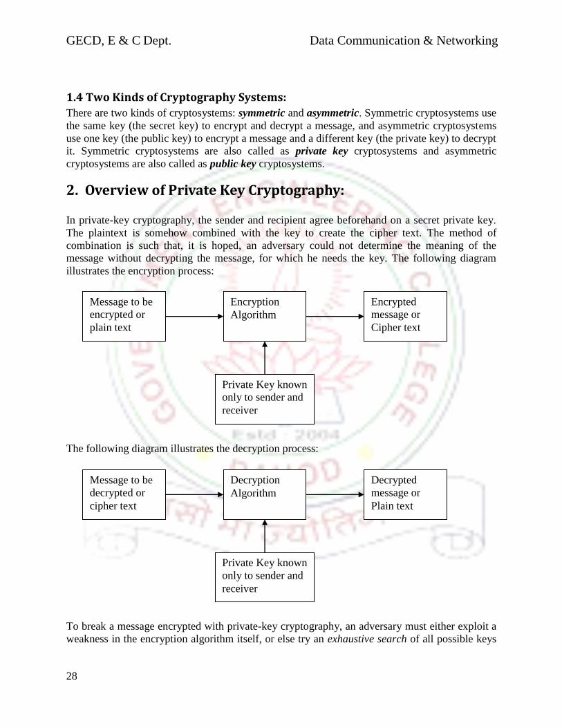
2. Overview of Private Key Cryptography:
In private-key cryptography, the sender and recipient agree beforehand on a secret private key.
The plaintext is somehow combined with the key to create the cipher text. The method of
combination is such that, it is hoped, an adversary could not determine the meaning of the
message without decrypting the message, for which he needs the key. The following diagram
illustrates the encryption process:
The following diagram illustrates the decryption process:
To break a message encrypted with private-key cryptography, an adversary must either exploit a
weakness in the encryption algorithm itself, or else try an exhaustive search of all possible keys
Message to be
encrypted or
plain text
Encryption
Algorithm
Encrypted
message or
Cipher text
Private Key known
only to sender and
receiver
Message to be
decrypted or
cipher text
Decryption
Algorithm
Decrypted
message or
Plain text
Private Key known
only to sender and
receiver

GECD, E & C Dept. Data Communication & Networking
29
(brute force method). If the key is large enough (e.g., 128 bits), such a search would take a very
long time (few years), even with very powerful computers.
Private-key methods are efficient and difficult to break. However, one major drawback is that the
key must be exchanged between the sender and recipient beforehand, raising the issue of how to
protect the secrecy of the key. When the President of the United States exchanges launch codes
with a nuclear weapons site under his command, the key is accompanied by a team of armed
couriers. Banks likewise use high security in transferring their keys between branches. These
types of key exchanges are not practical, however, for e-commerce between, say, amazon.com
and a casual web surfer.
3. Overview of Public Key Cryptography:
Public Key cryptography uses two keys Private key (known only by the recipient) and a Public
key (known to everybody). The public key is used to encrypt the message and then it is sent to
the recipient who can decrypt the message using the private key. The message encrypted with the
public key cannot be decrypted with any other key except for its corresponding private key. The
following Diagram illustrates the encryption process in the public key cryptography
The following diagram illustrates the decryption process in the public key cryptography:
Message to be
encrypted or
plain text
Encryption
Algorithm
Encrypted
message or
Cipher text
Public Key known
to everyone
Message to be
encrypted or
plain text
Encryption
Algorithm
Encrypted
message or
Cipher text
Private Key known
only to receiver
GECD, E & C Dept. Data Communication & Networking
30
The public-key algorithm uses a one-way function to translate plaintext to cipher text. Then,
without the private key, it is very difficult for anyone (including the sender) to reverse the
process (i.e., translate the cipher text back to plaintext). A one-way function is a function that is
easy to apply, but extremely difficult to invert. The most common one-way function used in
public-key cryptography involves factoring very large numbers. The idea is that it is relatively
easy to multiply numbers, even large ones, with a computer; however, it is very difficult to factor
large numbers. The only known algorithms basically have to do a sort of exhaustive search (Does
2 go in to? Does 3? 4? 5? 6? and so on). With numbers 128 bits long, such a search requires
performing as many tests as there are particles in the universe.
For instance, someone wishing to receive encrypted messages can multiply two very large
numbers together. She keeps the two original numbers a secret, but sends the product to anyone
who wishes to send her a message. The encryption/decryption algorithm is based upon
combining the public number with the plaintext. Because it is a one-way function, the only way
to reverse the process is to use one of the two original numbers. However, assuming the two
original numbers are very large, their product is even bigger; it would be impractical for an
adversary to try every possibility to determine what the two original numbers were.
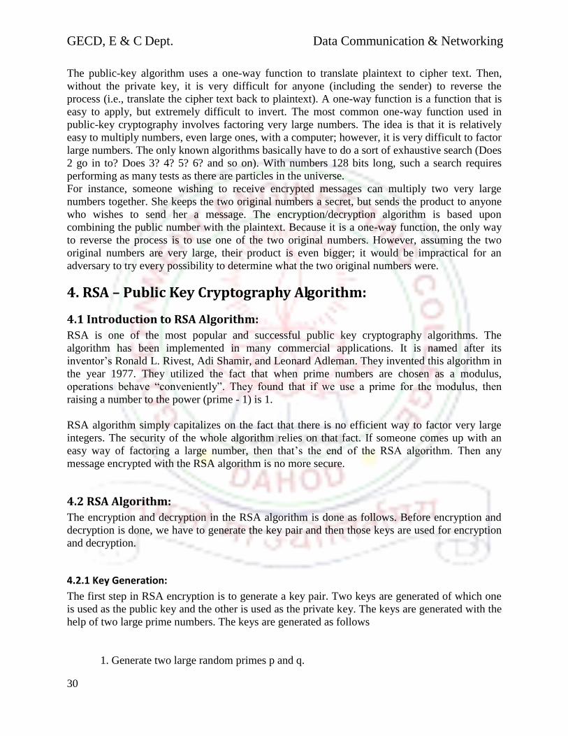
4. RSA – Public Key Cryptography Algorithm:
4.1 Introduction to RSA Algorithm:
RSA is one of the most popular and successful public key cryptography algorithms. The
algorithm has been implemented in many commercial applications. It is named after its
inventor’s Ronald L. Rivest, Adi Shamir, and Leonard Adleman. They invented this algorithm in
the year 1977. They utilized the fact that when prime numbers are chosen as a modulus,
operations behave “conveniently”. They found that if we use a prime for the modulus, then
raising a number to the power (prime - 1) is 1.
RSA algorithm simply capitalizes on the fact that there is no efficient way to factor very large
integers. The security of the whole algorithm relies on that fact. If someone comes up with an
easy way of factoring a large number, then that’s the end of the RSA algorithm. Then any
message encrypted with the RSA algorithm is no more secure.
4.2 RSA Algorithm:
The encryption and decryption in the RSA algorithm is done as follows. Before encryption and
decryption is done, we have to generate the key pair and then those keys are used for encryption
and decryption.
4.2.1 Key Generation:
The first step in RSA encryption is to generate a key pair. Two keys are generated of which one
is used as the public key and the other is used as the private key. The keys are generated with the
help of two large prime numbers. The keys are generated as follows
1. Generate two large random primes p and q.
GECD, E & C Dept. Data Communication & Networking
31
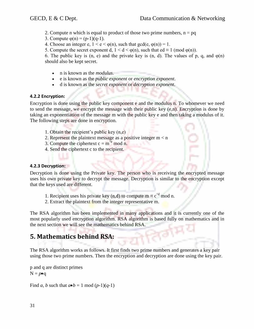
2. Compute n which is equal to product of those two prime numbers, n = pq
3. Compute φ(n) = (p-1)(q-1).
4. Choose an integer e, 1 < e < φ(n), such that gcd(e, φ(n)) = 1.
5. Compute the secret exponent d, 1 < d < φ(n), such that ed ≡ 1 (mod φ(n)).
6. The public key is (n, e) and the private key is (n, d). The values of p, q, and φ(n)
should also be kept secret.
n is known as the modulus.
e is known as the public exponent or encryption exponent.
d is known as the secret exponent or decryption exponent.
4.2.2 Encryption:
Encryption is done using the public key component e and the modulus n. To whomever we need
to send the message, we encrypt the message with their public key (e,n). Encryption is done by
taking an exponentiation of the message m with the public key e and then taking a modulus of it.
The following steps are done in encryption.
1. Obtain the recipient’s public key (n,e)
2. Represent the plaintext message as a positive integer m < n
3. Compute the ciphertext c = m^e
mod n.
4. Send the ciphertext c to the recipient.
4.2.3 Decryption:
Decryption is done using the Private key. The person who is receiving the encrypted message
uses his own private key to decrypt the message. Decryption is similar to the encryption except
that the keys used are different.
1. Recipient uses his private key (n,d) to compute m = c^d
mod n.
2. Extract the plaintext from the integer representative m.
The RSA algorithm has been implemented in many applications and it is currently one of the
most popularly used encryption algorithm. RSA algorithm is based fully on mathematics and in
the next section we will see the mathematics behind RSA.
5. Mathematics behind RSA:
The RSA algorithm works as follows. It first finds two prime numbers and generates a key pair
using those two prime numbers. Then the encryption and decryption are done using the key pair.
p and q are distinct primes
N = pq
Find a, b such that ab = 1 mod (p-1)(q-1)

GECD, E & C Dept. Data Communication & Networking
32
Encryption Key: e = (b, n)
Decryption Key: d = (a, n)
Encryption of message m: Ee(m) = mb mod n = C (cipher)
Decryption of C : Dd(C) = ca mod n = m
So in-order for RSA to work we must have the property :
(mb)a = m mod n
We have to prove that the above equation is true. If the above equation is proved then we can say
that the RSA algorithm really works. In the coming sections we will prove the above equation
and we will also look at the efficient ways of generating the prime numbers. We will also look at
how to find the keys a & b. There are many methods of finding these numbers and we will see a
few of them.
5.1 Preliminaries:
Before entering into the proofs, we must first know about the following terms and symbols in
order to follow it. These are basics of the RSA proof.
1. Zn = 0, 1, 2, … n-1. This set is very familiar. Zn is the set of integers from 0 to n-1.
2. Z*n = x <n-1 | x and n are relatively prime. Basically Z*n is the set that contains all the
numbers that is less than n and are relatively prime to n.
3. (n) = number of elements of Zn that are relatively prime to n. Hence (n) = | Z*n|
How to find (n)
We know that p and q are two prime numbers and n is the product of p and q. So n factors into p
and q. Therefore all those number that are not multiples of p or q are in (n). If we count all the
multiples of p and q, we get (n).
0, 1
p, 2p, 3p,…. (q-1)p = q-1
q, 2q, 3q,…. (p-1)q = p-1
hence to find the (n), we need to count all the multiples given above, which is nothing but
(n) = pq – 1 – (q– 1) – (p– 1) = pq – p – q +1 = (p– 1)(q– 1)
Example: p=3, q=5 n=15.
Now (n) = 2*4 = 8 = 1, 2, 4, 7, 8, 11, 13, 14
Before going to the proof of RSA lets have a look at some of the rules in the modulo arithmetic.
In the following sections, we will look at those rules and will prove some of them.
GECD, E & C Dept. Data Communication & Networking
33
5.1.1 Z*n is closed under multiplication mod n:
If a,b Z*n then ab and n are relatively prime i.e. ab shares no primes with n. By definition of
Z*n a, b do not share primes with n. Their product, ab, gets its primes from a and b and therefore
does not share primes with n.
The product can be written as ab = n + . We just need to show that is in Z*n . But if it is not,
then it shares primes with n and the right hand side is divisible by some prime that is a factor of
n. But then, so is the left side, which is impossible as we showed that it is relatively prime with n.
5.1.2 Sa Z*n:
Lets first define what Sa is. Before that we know that we can represent Z*n as
Z*n = b1, b2, … , b(n)
Now for any a Z*n,
Let Sa = ab1 mod n, ab2 mod n, …, ab(n) mod n
First, by the proof shown in the section 5.1.1, all elements of Sa are in Z*n
Second, no two elements can be the same. Suppose they were, then for some bi and bj (bi < bj)
a bi = n +
a bj = n +
Subtracting, (bi – bj)a = (-)n or x a = y n
x a and y n are the “same product of primes. Since a and n do not share any common primes.
All primes that form n has to appear in x.
Hence x>= n. That is a contradiction, as bj <n.
Since all elements of Sa are distinct, and in Z*n, then Sa and Z*n are identical. Note that since all
elements of Z*n are produced when a is multiplied by each element of Z*n, then the element 1 is
also a result of such a multiplication. Hence we get the following condition:
if a Z*n then bk Z*n, s.t. abk = 1 mod n
5.1.3 if a Z*n then a(n) = 1 mod n
To prove this, lets first define c and A such that:
b1 b2 … b(n) = c mod n
(ab1 ab2 … ab(n)) = A mod n [Note, A and c are less than n]
Now since ab1 mod n ab2 mod n … ab(n) = A mod n
By the proof in the section 5.1.2, ab1 mod n, ab2 mod n,… ab(n) mod n is a permutation of Z*n
Hence: A = c (plain arithmetic)

GECD, E & C Dept. Data Communication & Networking
34
Now distributing the sequence differently:
(ab1 ab2 … ab(n)) = a(n) (b1 b2 … b(n)) ….. [1]
Let a(n)
= mod n
Taking the modulo of both sides of [1] uses rule given below
A = c,
Replacing A with c, c = c , (plain arithmetic, not modulo).
Hence = 1.
Thus: a(n)
= 1 mod n
For all a, b Zn (not Z*n)
if (ab = c mod n) and (a = x mod n) and (b = y mod n) and (xy = z mod n)
then c = z
5.1.4 If a and (n) are relatively prime then b, s.t. ab = 1 mod (n)
If a and (n) are relatively prime, then a Z* (n) and from Corollary of Claim 2 we know that b
exists (and is a member of Z* (n)).
Thus there exists a and b, both relatively prime to (n), such that:
ab = k(n) + 1 (regular arithmetic)
5.1.5 Proof of RSA (for all messages in Z*n)
Take a message m < n and choose a relatively prime to (n) and find b such that a b=1 mod
(n).
Now compute (ma)b using modulo n arithmetic:
(ma)b = m
k(n) + 1 = m
k(n) m = m
(n) m
(n) … … m
(n) m
Take the modulo of the last term and since m(n)
= 1 mod n, then result is m.
Hence (ma)b = m mod n
Deficiency of this proof: The proof is for all messages in Z*n
If n=512 bit number, then the chance of a number being in Zn but not in Z*n is about 10–25
. That
is negligible.
5.1.6 How to really find a, b?
We know that given a, b exists, but how to find them?

GECD, E & C Dept. Data Communication & Networking
35
Find a, relatively prime number to n (3, 5, 7 etc – start with a small odd number and work your
way up). Note that (n) is even. To find b using extended Euclidean algorithm as follows
Extended Euclidean Algorithm:
Given p and q, p>q the algorithm finds x and y, such that
xp * yq = GCD(p, q) [note: regular arithmetic, x or y is negative]
So we use it as follows:
We provide n and a as input and get x and y [note: GCD(a,n) = 1]
We know ab = αn + 1
Or – αn + ab = 1
So b = y
Hence in modulo arithmetic,
b = y, if y is positive and
b = (n) – y, if y is negative
Hence the keys, a and b can be computed easily using the Extended Euclidian algorithm.
5.2 Finding Prime Numbers and hence the modulus N:
p and q are large prime numbers. So the problem is to find large prime numbers. Till recently
there was no good deterministic way of doing this. Very recently a Professor from the IIT
Kanpur, India and two of his students came up with a deterministic polynomial time algorithm
for finding if a number is prime or not. However, in prior years this was done with probabilistic
algorithms. There are very good probabilistic algorithms, which can generate prime numbers in a
very fast rate at 99.99% probability that the number given by that algorithm is a prime. The
actual fact is that there are lots of large prime numbers. The number of prime numbers below N
is about N/(ln n) and hence for a random 2048 bit number, the probability of it being prime is
about 0.0007(one in 1500).
5.2.1 Prime Number Hunt:
But how would we really find the prime numbers? There are many theorems available that can
be used to find if the given number is prime or not. One of the most popularly used theorems for
finding if a given number is prime or not is the Fermat’s little theorem. It states that for any a
that is less than p, ap-1
= 1 mod p. We can use this theorem to test the primality of a number,
called as primality testing. The proof of the theorem is given below.
Since p is prime, a Z* p and (p) = p – 1
Thus ap-1
= a(p)
= 1 mod p.
Now to find the prime number, we can do the following steps
GECD, E & C Dept. Data Communication & Networking
36
Choose a number p, randomly. This number, if large has a chance of being prime in the
order of 1 in several thousand.
Then choose a number a < p, randomly. We will use a to test the primality of p. First, we
know that if p is prime, ap-1
is 1 (mod p). Secondly, we know that if for some x (where x
is not 1 or p-1), if x2 is 1 or p-1 (mod p) then p is not prime.
6. Computational complexity of the RSA algorithm:
The computational complexity of the RSA algorithm completely depends upon the key length
and the length of the modulus n. We exponent the key with the message and take a modulus of
that value with the modulus n. So the computational complexity will depend upon these two
factors. To find the exponentiation, we can square the message and then multiply it again with
the squared value. For example to find 5^8, we can first find 5^2 by squaring 5 and then can find
5^4 by squaring the resulted value of 5^2 and then can find 5^8 by squaring the resulted value of
5^4. Hence the complexity of the encryption and decryption depends on how long the key is.
Well, when we compute the complexity of the RSA we will have to look at all the steps involved
in the protocol right from the Prime number generation. Lets leave the complexity of generating
prime numbers aside for a while, as we are going to look at a deterministic polynomial time
algorithm in order to find the prime p. So lets start with computing the complexities of the other
steps in RSA.
The computational complexity of RSA encryption and decryption of a single n bit block is
approximately O(n^3), with n is denoting both the block length and key length (exponent and
modulus). This is due to the complexity of multiplication is O(n^2 ), and the complexity of
exponentiation is O(n) when square and multiply is used. Although multiplication and
exponentiation algorithms exist that have lower asymptotic complexity, they are of limited
technical interest when n<1000 is assumed. If the message length m is sufficiently larger than the
block length n, the number of steps required to process a single message bit is of complexity
O(n^2 ). If a k bit datapath is used to speed up computation of n bit key length RSA, with k = n +
epsilon , the number of steps required to process a single message bit is O(n), as the complexity
of hardware is also O(n). When using shorter keys, e.g. 512 bit, the execution time decreases
approximately linearly.
The complexity of O(n^3) is clearly not a very high complexity since it is in polynomial time.
Next, we have to calculate the computational complexity of finding the encryption component e
and a decryption component d. This is done using the Extended Euclidian algorithm. That is we
need to find a number e, such that gcd(e, (n)) = 1. All the powering and gcd calculations are
clearly in polynomial time in the number of bits of n. Our task is to find a number e such that
gcd(e, (n)) = 1. We know that the fraction of elements, which are relatively prime to N, is (1/
logN). So setting N = (n), after o(logN) random trials for e, we should be able to get an e which
is prime to (n). This is still all polynomial in the number of bits of n.
Hence the complexity of the RSA algorithm is polynomial in time with respect to the length of
the key and the modulus, n.

GECD, E & C Dept. Data Communication & Networking
37
7. Primes is in P:
As we saw in the previous sections, Prime numbers are basis for RSA encryption and decryption.
But how do you know that the number we chose is prime or not? There has been research going
on for more than 200 years in finding out a good deterministic polynomial time algorithm which
will take a number as a input and will tell if it is prime or not in polynomial time. Till recently no
one was able to produce a deterministic polynomial time algorithm for this problem, though
there had been lot of random polynomial time algorithm and probabilistic algorithms available.
Recently in the year 2002, a professor and two of his students from the Indian Institute of
Technology, Kanpur came up with a deterministic polynomial time algorithm for this problem.
Thanks to them as the 200 year problem has been solved. In this section we will look at that
algorithm and how it works. In the next section, we will look at the complexity of the algorithm.
7.1 Basic notations:
In this section, we will look at some algebraic and number theoretic results, which the author of
this algorithm has used in the proofs. The symbol Fpd denotes the finite field, where p is a prime.
Recall that if p is a prime and h(x) is a polynomial of degree d and irreducible in Fp, then
Fp[x]=(h(x)) is a finite field of order pd.
Next h(x) will be a factor of xr-1/x-1 unless stated otherwise. The author has used the symbol
~O(t(n)) for O(t(n)poly(log t(n))), where t(n) is some function of n. Unless stated otherwise, the
author uses log with respect to base 2.
Next look at some of the algebraic results that are useful in understanding this algorithm. Let p
and r be prime numbers, p != r. the following results are observed and some of the results were
proved by the author. In this section I am just producing the rules that are used and for the
proofs, please refer to the original paper by the authors.
1. The multiplicative group of any field Fpt for t > 0, denoted by F*pt is cyclic.
2. Let f(x) be a polynomial with integral coefficients. Then
f(x)p f(x
p) (mod p)
3. Let h(x) be any factor of xr - 1. Let m mr (mod r). Then
xm
xm
r (mod h(x)):
4. Let or(p) be the order of p modulo r. Then in Fp, xr-1/x-1 factorises into irreducible
polynomials each of degree or(p).
In addition to the above algebraic facts, we will need the following two number theoretic facts.
Let P(n) denote the greatest prime divisor of n. There exist constants c > 0 and n0 such
that, for all x >= n0
|P| P is prime, P<=x and P(p-1) > x2/3
| >= C x/log x
Let (n) be the number of primes <= n. Then for n >= 1
n/6log n <= (n) <= 8n/log n

GECD, E & C Dept. Data Communication & Networking
38
7.2 Algorithm:
The algorithm that computes and tells if the given number is prime or not is given below. This
algorithm gets an input that is greater than 1 and computes and outputs either COMPOSITE or
PRIME.
Input: integer n > 1
1. if ( n is of the form ab, b > 1 ) output COMPOSITE;
2. r = 2;
3. while(r < n)
4. if ( gcd(n,r) != 1 ) output COMPOSITE;
5. if (r is prime)
6. let q be the largest prime factor of r - 1;
7. if (q >= 4r log n) and (nr-1/q
! (mod r)
8. break;
9. r = r + 1;
10.
11. for a = 1 to 2r log n
12. if ( (x - a)n ! (x
n - a) (mod x
r – 1, n)) output COMPOSITE;
13. output PRIME;
The above algorithm returns PRIME is n is prime and returns COMPOSITE if n is composite.
Lets look at how it works by looking at the correctness of the algorithm. The author has proved
that the above algorithm works properly. Lets look at how it works.
7.3 Correctness of the Algorithm:
7.3.1 If n is prime, the algorithm returns PRIME.
The while loop cannot return COMPOSITE since gcd(n, r) = 1 for all r <= c2(log n)6, where c2 is
defined in one of the lemmas given by the author. We know by the fact 2 that the for loop also
cannot return COMPOSITE. Thus, algorithm will identify n as PRIME. Now let us turn our
attention to the case where a composite n is input to our algorithm. The significance of the r
found by the while loop arises when n is composite with say pi; 1 <= i <= k, as its prime factors.
In this case or(n) | lcmior(pi) and hence there exists a prime factor p of n such that q | or(p),
where q is the largest prime factor of r-1. For the remainder of the argument, let p be such a
prime factor of n.
The second loop of the algorithm uses the value of r obtained to do polynomial computations on
l = 2r log n binomials: (x-a) for 1 <= a <= l. By fact 4, we have a polynomial h(x) (factor of xr _
1) of degree d = or(p) irreducible in Fp. Note that

GECD, E & C Dept. Data Communication & Networking
39
(x - a)n (x
n - a)(mod x
r - 1, n)
the above equation implies that
(x - a)n (x
n - a)(mod h(x), p)
So the identities on each binomial hold in the field Fp[x]/(h(x)). The set of l binomials form a
large cyclic group in this field.
7.3.2 If n is composite, the algorithm returns COMPOSITE.
Suppose that the algorithm returns PRIME instead. Thus, the for loop ensures that for all
1 <= a <= 2r log n,
(x - a)n (x
n - a)(mod x
r - 1, p)
Notice that g(x) is just a product of powers of l binomials (x _ a), (1 <= a <= l) all of which
satisfy the above equation. Thus,
g(x)n g(x
n) (mod x
r _ 1, p)
Then author goes on to use two more lemmas that he has showed in his paper to determine the
values of Ig(x). Finally he proves that n = p is a contradictory. Hence the algorithm returns
COMPOSITE if n is composite.
7.4 Time Complexity Analysis of the algorithm:
The author has calculated the time complexity of the algorithm in a pretty straightforward
manner and the asymptotic time complexity of the algorithm turns out to be O(log12
n).
Calculation of the time complexity:
The first step of the algorithm takes asymptotic time O(log3 n). As noted during the analysis of
the algorithm in the previous section, the while loop makes O(log6 n) iterations. Let us now
measure the work done in one iteration of the while loop. The first step (gcd computation) takes
poly(log log r) asymptotic time. The next two steps would take atmost r1/2
poly(log log n) time in
the brute-force implementation. The next three steps take atmost poly(log log n) steps. Thus,
total asymptotic time taken by the while loop is
O(log6n . r
1/2 ) = O(log
9 n).
The for loop does modular computation over polynomials. If repeated-squaring and Fast-Fourier
Multiplication is used then one iteration of this for loop takes O(log n_r log n) steps. Thus, the
for loop takes asymptotic time
GECD, E & C Dept. Data Communication & Networking
40
O(r3/2
log3 n) = O(log
12 n).
In practice, however, this algorithm is likely to work much faster. The reason is that even though
we only know that there are “many" primes r such that P(r - 1) > r2/3, a stronger property is
believed to be true. In fact it is believed that for many primes r,
P(r - 1) = (r –1)/2 .
Such primes are called Sophie Germain primes.
This ends the time complexity computation of the algorithm. As per the author, they are trying to
improve the running time complexity of the algorithm to O (log3 n).
8. Comparison of the RSA algorithm with other algorithms:
RSA is one of the most popularly used cryptography algorithms, but still there are many other
algorithms that are being used today. One of the popularly used algorithms other than RSA is
Elliptic Curve (EC) cryptography algorithm. Let’s first see a comparison with the EC algorithm
8.1 Comparison with EC algorithm:
People say that ECC is very much faster than RSA, but actually ECC is significantly faster than
RSA only when used with precomputed values. That is, you can store your ECC key in a small
space, but if you want to get the performance advantage, you also have to store some tables of
precomputed values. These tables can be as many as 20,000 bytes. But if you don’t have 20,000
bytes of storage space lying around (say your smart card), you may not be able to use the
precomputed tables. But if you don’t, the ECC is not that much faster than RSA. With ECC you
can sign fast or save storage space, but you can’t do both. Of course, saving storage space and
transmission size may be reason enough.
Furthermore, using ECC with or without precomputed values to perform key exchange is not that
much faster than RSA. So the only real advantage to using ECC to perform key exchange is key
and transmission size.
Another disadvantage to ECC is certificates. Public-key crypto does not really work without
digital certificates, and digital certificates don’t really work without certificate authorities. It’s
hard to find ECC digital certificates. So even if you want to use ECC, you might not be able to
get a certificate.
Currently in the industry, RSA is winning. The key size, transmission size and signature
performance issues concern makers of small devices. But they often find that RSA is fast and

GECD, E & C Dept. Data Communication & Networking
41
small enough. Sure, it’s not the fastest signer or the smallest key, but it still works just fine. And
RSA has a well-developed certificate infrastructure.
9. Conclusion:
RSA algorithm had been in use for the past 25 years and it’s been one of the most successful
cryptography algorithms that the security world ever had. This is still widely used in many
applications even after hundreds of public key cryptography algorithms emerged after the
invention of RSA algorithm. This algorithm is still in use because of its security and easy
implementation.
The security of the RSA algorithm lies in the fact that there is no good way of factoring numbers.
No one till now knows a way to factorize a number into its prime factors. As long as no one finds
a way RSA will be safe and will be one of the best encryption algorithm in use. If someone
comes up with a way to factorize algorithms, then that’s the end of RSA.
RSA had a patent towards its inventors till 2000. The patent was removed on 2000 and now its
open to all. Anybody can use it now. This makes it still easier to study the algorithm in a more
detailed manner and it will certainly be reviewed by many other people all over the world and
there is a lot of chances that someone will come up with another version of RSA which is lot
more sophisticated than this one.
The RSA Security inc, which held the patent for RSA had announced lot of cash prizes for the
people who could come up with factors of few large numbers. The numbers are nearly 200 digits
long and it is published in their website.
Finally, a few days back the inventors of the RSA Ronald Rivest, Adi Shamir and Leonard
Adleman received the Turing Award for the year 2002 for their invention of RSA algorithm.
This is really great news and obviously these people deserve this award for having created such a
wonderful algorithm, which dominated the world of cryptography for about 25 years and is still
dominating.
The recent development of the prime number algorithm by the Indian students and professor will
also have a great impact in the field of cryptography. This will certainly help the cryptography
algorithms in finding the prime numbers easily and will greatly reduce the running time
complexity.
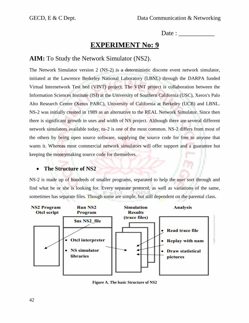
GECD, E & C Dept. Data Communication & Networking
42
Date : ___________
EXPERIMENT No: 9
AIM: To Study the Network Simulator (NS2).
The Network Simulator version 2 (NS-2) is a deterministic discrete event network simulator,
initiated at the Lawrence Berkeley National Laboratory (LBNL) through the DARPA funded
Virtual Internetwork Test bed (VINT) project. The VINT project is collaboration between the
Information Sciences Institute (ISI) at the University of Southern California (USC), Xerox's Palo
Alto Research Centre (Xerox PARC), University of California at Berkeley (UCB) and LBNL.
NS-2 was initially created in 1989 as an alternative to the REAL Network Simulator. Since then
there is significant growth in uses and width of NS project. Although there are several different
network simulators available today, ns-2 is one of the most common. NS-2 differs from most of
the others by being open source software, supplying the source code for free to anyone that
wants it. Whereas most commercial network simulators will offer support and a guarantee but
keeping the moneymaking source code for themselves.
The Structure of NS2
NS-2 is made up of hundreds of smaller programs, separated to help the user sort through and
find what he or she is looking for. Every separate protocol, as well as variations of the same,
sometimes has separate files. Though some are simple, but still dependent on the parental class.
Figure A. The basic Structure of NS2
GECD, E & C Dept. Data Communication & Networking
43
C++
C++ is the predominant programming language in ns-2. It is the language used for all the small
programs that make up the ns-2 hierarchy. C++, being one of the most common programming
languages and specially designed for object- oriented coding, was therefore a logical choice what
language to be used. This helps when the user wants to either understand the code or do some
alterations to the code. There are several books about C++ and hundreds, if not thousands, of
pages on the Internet about C++ simplifying the search for help or answers concerning the ns-
2 code.
OTcl
Object Tcl (OTcl) is object-oriented version of the command and syntax driven programming
language Tool Command Language (Tcl). This is the second of the two programming languages
that NS-2 uses. The front-end interpreter in NS-2 is OTcl which link the script type language of
Tcl to the C++ backbone of NS-2. Together these two different languages create a script
controlled C++ environment. This helps when creating a simulation, simply writing a script that
will be carried out when running the simulation. These scripts will be the formula for a
simulation and is needed for setting the specifications of the simulation itself. Without a script
properly defining a network topology as well as the data-rows, both type and location,
nothing will happen.
Nodes
A node is exactly what it sounds like, a node in the network. A node can be either an end
connection or an intermediate point in the network. All agents and links must be connected to a
node to work. There are also different kinds of nodes based on the kind of network that is to be
simulated. The main types are node and mobile node, where node is used in most wired networks
and the mobile node for wireless networks. There are several different commands for setting the
node protocols to be used, for instance what kind of routing is to be used or if there is a desire to
specify a route that differs from the shortest one. Most of the commands for node and mobile
node can be easily found in the ns documentation. Nodes and the closely connected link creating
commands, like simplex link and duplex link, could be considered to simulate the behavior of
both the Link Layer.
GECD, E & C Dept. Data Communication & Networking
44
Agents
An agent is the collective name for most of the protocols you can find in the transport layer. In
the ns-2 documentation agents are defined as the endpoints where packets are created and
consumed. All the agents defined in ns-2, like tcp, udp etc., are all connected to their parent
class, simply called Agent. This is where their general behavior is set and the offspring classes
are mostly based on some alterations to the inherent functions in the parent class. The modified
functions will overwrite the old and thereby change the performance in order to simulate the
wanted protocol.
Applications
The applications in ns-2 are related to the Application Layer in the TCP/IP suite. The
hierarchy here works in the similar way as in the agent’s case. To simulate some of the most
important higher functions in network communication, the ns-2 applications are used. Since the
purpose of ns-2 is not to simulate software, the applications only represent some different aspects
of the higher functions. Only a few of the higher layer protocols has been implemented, since
some are quite similar when it comes to using the lower functions of the TCP/IP stack. For
instance there is no use adding both a SMTP and a HTTP application since they both use TCP to
transfer small amounts of data in a similar way. The only applications incorporated in the release
version of ns-2 are a number of different traffic generators for use with UDP and telnet and FTP
for using TCP. All the applications are script controlled and when concerning the traffic
generators, you set the interval and packet-size of the traffic. FTP can be requested to send a data
packet whenever the user wants to, or to start a transfer of a file of arbitrary size. If starting an
FTP transmission and not setting a file-size the transmission will go on until someone calls a
stop.
NAM
The Network Animator NAM is a graphic tool to use with ns-2. It requires a nam-tracefile
recorded during the simulation and will then show a visual representation of the simulation. This
will give the user the possibility to view the traffic packet by packet as they move along the
different links in the network. NAM offers the possibility of tracing a single packet during its
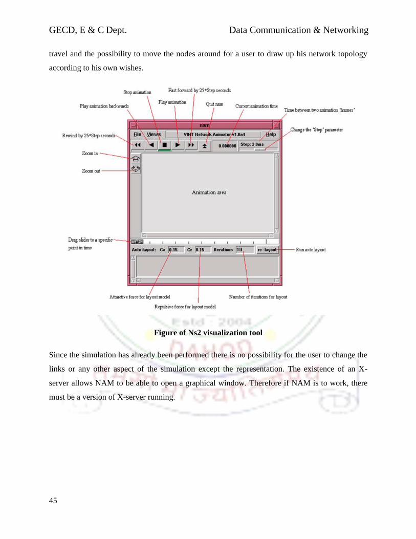
GECD, E & C Dept. Data Communication & Networking
45
travel and the possibility to move the nodes around for a user to draw up his network topology
according to his own wishes.
Figure of Ns2 visualization tool
Since the simulation has already been performed there is no possibility for the user to change the
links or any other aspect of the simulation except the representation. The existence of an X-
server allows NAM to be able to open a graphical window. Therefore if NAM is to work, there
must be a version of X-server running.

GECD, E & C Dept. Data Communication & Networking
46
Date : ___________
EXPERIMENT No: 10 AIM: To implement wired network topology and wireless network
Topology in ns2
FOR WIRED TOPOLOGY
ALGORITHMS:
1 Define new simulator.
2 Create n numbers of nodes.
3 Set the link between each of the nodes.
4 Create agent
5 Attach the agent
6 Trace the protocols using CBR & FTP.
7 Define a’ finish’ procedure –to flush trace record in the trace and trace
output files.
8 Schedule events for simulation.
9 Run the simulation.
FOR WIRELESS TOPOLOGY
ALGORITHMS:
1 Define new simulator.
2 Define the network components. Such as the type of antenna, the radio-
propagation model, the type of ad-hoc routing protocol used by mobile
node.
3 Create n numbers of nodes.
4 Set the link between each of the nodes
5 Create agent.
6 Attach the agent.
7 Trace the protocols using application type.
8 Define a’ finish’ procedure –to flush trace record in the trace and trace
output files.

GECD, E & C Dept. Data Communication & Networking
47
8 Schedule events for simulation
9 Run the simulation.
GECD, E & C Dept. Data Communication & Networking
48
Date : ___________
EXPERIMENT No: 11
AIM: To implement UDP protocol and study performance using
Network simulator (ns2)
ALGORITHMS:
1 Define new simulator.
2 Create n numbers of nodes.
3 Set the link between each of the nodes
4 Create UDP & TCP agent.
5 Attach the UDP & TCP agent.
6 Trace the protocols using CBR & FTP.
7 Define a’ finish’ procedure –to flush trace record in the trace and trace
output files.
8 Schedule events for simulation.
9 Run the simulation.

GECD, E & C Dept. Data Communication & Networking
49
Date: __________
EXPERIMENT No: 12
AIM: To Connect the computers in Local Area Network.
Procedure: On the host computer
On the host computer, follow these steps to share the Internet connection:
1. Log on to the host computer as Administrator or as Owner.
2. Click Start, and then click Control Panel.
3. Click Network and Internet Connections.
4. Click Network Connections.
5. Right-click the connection that you use to connect to the Internet. For example, if you
Connect to the Internet by using a modem, right-click the connection that you want
under Dial-up / other network available.
6. Click Properties.
7. Click the Advanced tab.
8. Under Internet Connection Sharing, select the Allow other network users to connect
through this computer's Internet connection check box.
9. If you are sharing a dial-up Internet connection, select the Establish a dial-up
connection whenever a computer on my network attempts to access the Internet
check box if you want to permit your computer to automatically connect to the Internet.
10. Click OK. You receive the following message:
When Internet Connection Sharing is enabled, your LAN adapter will be set to use IP
address 192.168.0.1. Your computer may lose connectivity with other computers on
your network. If these other computers have static IP addresses, it is a good idea to set
them to obtain their IP addresses automatically. Are you sure you want to enable Internet
Connection Sharing?
11. Click Yes.
The connection to the Internet is shared to other computers on the local area network (LAN). The

GECD, E & C Dept. Data Communication & Networking
50
Network adapter that is connected to the LAN is configured with a static IP address of
192.168.0.1 and a subnet mask of 255.255.255.0
On the client computer
To connect to the Internet by using the shared connection, you must confirm the LAN adapter
IP configuration, and then configure the client computer. To confirm the LAN adapter IP
Configuration, follow these steps:
1. Log on to the client computer as Administrator or as Owner.
2. Click Start, and then click Control Panel.
3. Click Network and Internet Connections.
4. Click Network Connections.
5. Right-click Local Area Connection and then click Properties.
6. Click the General tab, click Internet Protocol (TCP/IP) in the connection uses the
Following items list, and then click Properties.
7. In the Internet Protocol (TCP/IP) Properties dialog box, click Obtain an IP address
Automatically (if it is not already selected), and then click OK.
Note: You can also assign a unique static IP address in the range of 192.168.0.2 to
192.168.0.254. For example, you can assign the following static IP address, subnet mask,
and default gateway:
8. IP Address 192.168.31.202
9. Subnet mask 255.255.255.0
10. Default gateway 192.168.31.1
11. In the Local Area Connection Properties dialog box, click OK.
12. Quit Control Panel.