Data Communication and Computer Networksweb.cse.msstate.edu/~ramkumar/CSE4153Introduction.pdfData...
77
Introduction Network Components Network Model Data Communication and Computer Networks Mahalingam Ramkumar Mississippi State University, MS August 16, 2015 Ramkumar CSE 4153 / 6153
Transcript of Data Communication and Computer Networksweb.cse.msstate.edu/~ramkumar/CSE4153Introduction.pdfData...

IntroductionNetwork Components
Network Model
Data Communication and Computer Networks
Mahalingam RamkumarMississippi State University, MS
August 16, 2015
Ramkumar CSE 4153 / 6153

IntroductionNetwork Components
Network Model
1 Introduction
2 Network ComponentsFunctional OrganizationPhysical OrganizationIP Address StructureAutonomous Systems
3 Network ModelTCP/IP ModelSocketsTasks By LayerAdditional OSI Layers
2 / 61

IntroductionNetwork Components
Network Model
Data Communication Networks
Data (digital data in the form of bits)
Communication (exchange of data)
Network (the facilitator)
For the purposes of this course:
bits (chunks, streams, or packets) exchanged betweencomputers;The network is the Internet
3 / 61

IntroductionNetwork Components
Network Model
Expectations
For advanced Juniors, Seniors and Graduate students
No hand-holding; no text book.
Broad topics/concepts will be discussed. You are expected toeffectively utilize other online resources
C or C++ (for socket programming assignments)
Self-learn useful tools for implementing simulations in projects
Choose your own tool (Python numpy/scipy,Matlab/Octave/Freemat etc.)
Self-learn tools like Wireshark, tcpdump, etc., for capturingand analysing network packets
4 / 61

IntroductionNetwork Components
Network Model
Grading Policies
Quizzes/Assignments 30%
Exams 35% (15+20)
Programming Assignments 10%
Projects 15% (can earn bonus points)
Participation 10%
5 / 61

IntroductionNetwork Components
Network Model
Course Outline
Overview of the Internet; layered models
Data Communication Principles
Internet Practices
6 / 61
IntroductionNetwork Components
Network Model
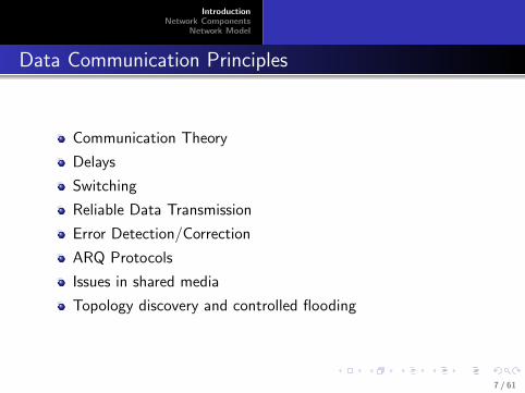
Data Communication Principles
Communication Theory
Delays
Switching
Reliable Data Transmission
Error Detection/Correction
ARQ Protocols
Issues in shared media
Topology discovery and controlled flooding
7 / 61

IntroductionNetwork Components
Network Model
Internet Practices
Protocols in different Internet layers
DL/MAC layer protocolsIP protocolTCP and UDPSocket Library
Applications
8 / 61

IntroductionNetwork Components
Network Model
Why Digital?
More Efficient
eg., analog vs digital TV
Great equalizer — for transmission/reception, storage andprocessing
Does not matter if data is video, audio, image or document, oranything else
Better suited for long range transmission
Can use repeatersWhy is this not suitable for analog transmission?
9 / 61

IntroductionNetwork Components
Network Model
Terminology
Protocol (rigid rules/steps to be followed)
Bit-rate (Kbps, Mbps, Gbps)
Storage (KB, MB, GB, TB)
Useful to be comfortable with powers of 2
210 = 1024 ≈ 1000, 220 ≈ 1, 000, 000 (million),230 ≈ 1, 000, 000, 000 (billion)
IP (Internet Protocol) address, 32-bit unsigned number
For convenience represented as 4 1-byte (8-bit) numbers(each in the range 0 to 255)
Example, 129.36.42.207.
10 / 61

IntroductionNetwork Components
Network Model
Some Interesting Quantities
28 = 256 possible byte values (0 to 255)
210 = 1024 ≈ 1000
216 = 256× 256 = 65536; number of port numbers
220 ≈ 1 million. 230 ≈ 1 billion.
225 ≈ number of seconds in a year.
232 ≈ 4 billion (no. of IPv4 addresses, world population 1975)
233 ≈ 8 billion (world population in 2020?)
242 ≈ 4 trillion (federal budget in 2015)
248 ≈ 256 trillion (number of unique MAC addresses)
264 ≈ grains of sand in all beaches in the world
278 ≈ number of water molecules in a Tbsp of water
297 ≈ number of stars in the observable universe
2128 ?
2266 number of baryons in the observable universe
11 / 61

IntroductionNetwork Components
Network Model
Functional OrganizationPhysical OrganizationIP Address StructureAutonomous Systems
Network Components
Hosts (users of the network) & Network Infrastructure(provider)
Postal Network: sender receiver; USPS
Telephone network: caller and callee (subscribers); Telephonecompanies (network)
Mobile Telephone: subscribers; service provider.
12 / 61

IntroductionNetwork Components
Network Model
Functional OrganizationPhysical OrganizationIP Address StructureAutonomous Systems
Internet Components
Network Hosts & Network Infrastructure
Host computers: Clients and servers
Infrastructure: Internet service providers (ISP)
ISPs in different tiers. Tier III ISPs rely on Tier II ISPs, andso on
Tier I ISPs are “Backbone operators.”
Some large users (eg., Google, Netflix, Amazon, Yahoo) mayconnect directly to Tier I ISPs.
Infrastructure components: Routers and Links (fiber, twistedpair, coax, wireless, satellite)
13 / 61

IntroductionNetwork Components
Network Model
Functional OrganizationPhysical OrganizationIP Address StructureAutonomous Systems
Classical Telephone Network
Telephones connected by a wire (twisted pair copper) to alocal switching office (up to 10000 phones)
Several local switching offices are connected to an areaswitching office (up to 1000 LSO per ASO)
Area switching offices are interconnected (1000 ASOs)
Each wire (from a phone to a switching office) is associatedwith a unique (phone) number — eg. (662) 323-xxxx
area code 662 identifies area switching office323 identifies local switching office;every wire terminating at switching office 323 has a uniquefour digit number xxxx.
14 / 61

IntroductionNetwork Components
Network Model
Functional OrganizationPhysical OrganizationIP Address StructureAutonomous Systems
Classical Telephone Network
When the telephone receiver is lifted off the base the wire isactivated (user hears a dial tone)
User dials a destination number
this is an instruction to the LSO to establish a path betweenthe two phones
662 323 5678 ↔ 301 506 7259
662 323 5678 ↔ LSO 323 ↔ ASO 662 ↔ ASO 301 ↔ LSO506 ↔ 301 506 7259
the path can be used for sending electrical signals between thetwo phones.
15 / 61

IntroductionNetwork Components
Network Model
Functional OrganizationPhysical OrganizationIP Address StructureAutonomous Systems
Classical Telephone Network
Mouthpiece converts sound vibrations (pressure) to anelectrical signal
Electrical signals conveyed over the wire (at the speed of lightin copper) to the telephone at the other end.
At the receiver, earpiece converts electrical signals to pressurevibrations (sound)
Replacing the telephone on the hook terminates theconnection.
Telephone company keeps a record of the destination andduration of your call (for billing purposes).
16 / 61

IntroductionNetwork Components
Network Model
Functional OrganizationPhysical OrganizationIP Address StructureAutonomous Systems
Postal Network
Users address mail/packages and drop them into boxes.
Picked up by postal carriers
Depending on the final destination the mail/package may berouted over several hops
Possibly different modes of transportation at each hop (foot,bicycle, van, train, airplane, · · · )Mail finally delivered to the destination address.
Postal network uses packet switching. Telephone networkuses circuit switching
17 / 61

IntroductionNetwork Components
Network Model
Functional OrganizationPhysical OrganizationIP Address StructureAutonomous Systems
Postal Network vs Telephone Network
Postal network uses packet switching.
Telephone network uses circuit switching.
18 / 61

IntroductionNetwork Components
Network Model
Functional OrganizationPhysical OrganizationIP Address StructureAutonomous Systems
The Internet at a Glance
Hosts (computers), inter-connected routers (subnet);
Every host has a unique IP address (32-bit address, about 4billion unique addresses).
Any host can send a packet (an IP packet) to any host.
IP packets have a header indicating the IP addresses of thesender and the destination.
IP packet also have a payload (any data that the sending hostwants to send to the destination host)
IP Packets are typically delivered over multiple hops — arouter at each hop.
19 / 61

IntroductionNetwork Components
Network Model
Functional OrganizationPhysical OrganizationIP Address StructureAutonomous Systems
Routers and Links
Every host has a direct connection to one router.
A router can determine the best path to any other router.
Does packet switching.
At each link (between any two hops) IP packets are carriedinside a data-link frame
the type of the data-link frame depends on the physical natureof the link (fiber, twisted pair, coax, wireless, satellite, etc.)
20 / 61

IntroductionNetwork Components
Network Model
Functional OrganizationPhysical OrganizationIP Address StructureAutonomous Systems
Packet Switching in the Internet
Sending process Receiving process
Sending host
Router Subnet
Router C makes a choice to forward packets to E and not to D
Packet
Receiving hostDB
A E
C
21 / 61

IntroductionNetwork Components
Network Model
Functional OrganizationPhysical OrganizationIP Address StructureAutonomous Systems
Postal Network vs Internet
The Internet is more like the postal network (and less like thetelephone network)
Both employ packet switchingStreet Address ↔ IP addressPostal envelopes ↔ IP packets;Post office sorting facilities ↔ routerstransportation modes (road+truck) ↔ link + data-link frames
22 / 61

IntroductionNetwork Components
Network Model
Functional OrganizationPhysical OrganizationIP Address StructureAutonomous Systems
Postal Network vs Internet
Postal envelopes carry a letter from sender to receiver; IPpackets carry an application message;
different transportation mechanisms over each hop
truck over road, train over rails, ships over oceans/waterwaysetc.different types of data-link frames over different types ofphysical layers;Ethernet over twisted pair, Wireless Ethernet over air, ALOHAover satellite links, FTTH over fiber, etc.
The main difference is the speed — IP packets travel at thespeed of light
The Internet is postal network on steroids!
23 / 61

IntroductionNetwork Components
Network Model
Functional OrganizationPhysical OrganizationIP Address StructureAutonomous Systems
Virtual Link Between Hosts
The speed of exchanges motivates sophisticated Internetbased applications
Applications running on hosts use the Internet tocommunicate with applications running on other hosts(possibly even at the other side of the globe)
From the perspective of applications, the Internet enables avirtual link between hosts.
24 / 61

IntroductionNetwork Components
Network Model
Functional OrganizationPhysical OrganizationIP Address StructureAutonomous Systems
Functional Organization — Internet Layers
Application Layer (AL)
Transport Layer (TL)
Network Layer (NL)
Data-Link Layer (DL)
Physical Layer (PL)
Each layer has a specific function.
Components in one layer can be modified without affectingother layers.
All Top Notch Donut Places (useful? mnemonic)
25 / 61

IntroductionNetwork Components
Network Model
Functional OrganizationPhysical OrganizationIP Address StructureAutonomous Systems
Lower and Upper Layers
The two lower layers (PL and DL) are necessary for thefunctioning of the NL (to create a virtual link between hosts)
The two upper layers (TL and AL) are required to use thevirtual link
26 / 61
IntroductionNetwork Components
Network Model
Functional OrganizationPhysical OrganizationIP Address StructureAutonomous Systems
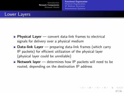
Lower Layers
Physical Layer — convert data-link frames to electricalsignals for delivery over a physical medium
Data-link Layer — preparing data-link frames (which carryIP packets) for efficient utilization of the physical layer(physical layer could be unreliable)
Network layer — determines how IP packets will need to berouted, depending on the destination IP address
27 / 61
IntroductionNetwork Components
Network Model
Functional OrganizationPhysical OrganizationIP Address StructureAutonomous Systems
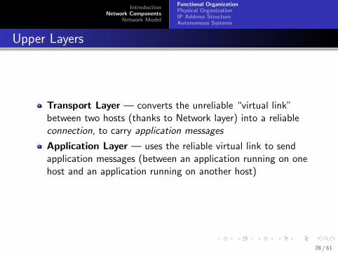
Upper Layers
Transport Layer — converts the unreliable “virtual link”between two hosts (thanks to Network layer) into a reliableconnection, to carry application messages
Application Layer — uses the reliable virtual link to sendapplication messages (between an application running on onehost and an application running on another host)
28 / 61

IntroductionNetwork Components
Network Model
Functional OrganizationPhysical OrganizationIP Address StructureAutonomous Systems
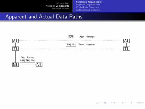
Apparent and Actual Data Paths
AL ALAM App. Message
TL TLTH‖AM Trans. Segment
NL NLNH‖TH‖AMNet. Packet
DL DLDL Frame DL Frame = DH‖NH‖TH‖AM‖DF
PL PL
NL
DL
PL
NL
DL
PL
Virtual Link
29 / 61

IntroductionNetwork Components
Network Model
Functional OrganizationPhysical OrganizationIP Address StructureAutonomous Systems
Apparent and Actual Data Paths
AL ALAM App. Message
TL TLTH‖AM Trans. Segment
NL NLNH‖TH‖AMNet. Packet
DL DLDL Frame DL Frame = DH‖NH‖TH‖AM‖DF
PL PL
NL
DL
PL
NL
DL
PL
Virtual Link
29 / 61

IntroductionNetwork Components
Network Model
Functional OrganizationPhysical OrganizationIP Address StructureAutonomous Systems
Apparent and Actual Data Paths
NL NL
DL DL
PL PL
DL
PL
30 / 61

IntroductionNetwork Components
Network Model
Functional OrganizationPhysical OrganizationIP Address StructureAutonomous Systems
Physical Organization
Several hosts connected to a router in the same local areanetwork (LAN)
LANs may be interconnected by routers to form smallnetworks
small networks may be interconnected to form larger networks(for example, an organization)
organizations connect to an Internet Service Provider (ISP)
ISPs may form several tiers
lower tier ISPs connect to higher tier ISPs
ISPs at the highest tier interconnected by the Internetbackbones.
31 / 61

IntroductionNetwork Components
Network Model
Functional OrganizationPhysical OrganizationIP Address StructureAutonomous Systems
LAN
Cable Computer
(b)(a)
Computer
32 / 61

IntroductionNetwork Components
Network Model
Functional OrganizationPhysical OrganizationIP Address StructureAutonomous Systems
Interconnection of LANs
Subnet Router
Host
LAN
33 / 61

IntroductionNetwork Components
Network Model
Functional OrganizationPhysical OrganizationIP Address StructureAutonomous Systems
Interconnection of Networks
R1
R2
R3
R4
R5
R6
R7
R1
R2
R3
R4
R5R6
R7
ISP
34 / 61

IntroductionNetwork Components
Network Model
Functional OrganizationPhysical OrganizationIP Address StructureAutonomous Systems
Interconnection of Networks
R1
R2
R3
R4
R5
R6
R7
R1
R2
R3
R4
R5R6
R7
ISP
34 / 61

IntroductionNetwork Components
Network Model
Functional OrganizationPhysical OrganizationIP Address StructureAutonomous Systems
Interconnection of Networks
R1
R2
R3
R4
R5
R6
R7
R1
R2
R3
R4
R5R6
R7
ISP
34 / 61

IntroductionNetwork Components
Network Model
Functional OrganizationPhysical OrganizationIP Address StructureAutonomous Systems
Interconnection of Networks
R1
R2
R3
R4
R5
R6
R7
R1
R2
R3
R4
R5R6
R7
ISP
34 / 61

IntroductionNetwork Components
Network Model
Functional OrganizationPhysical OrganizationIP Address StructureAutonomous Systems
Interconnection of ISPs
i1
i2
i3 i4
i5
i6
i7
i8i9
i0
Tier II
Tier III
I1
I2
I3 I4
I5
I6
I7
I8I9
Ia
Tier IB1
B2
B3
B4
B5
B6
B7
B8
35 / 61

IntroductionNetwork Components
Network Model
Functional OrganizationPhysical OrganizationIP Address StructureAutonomous Systems
IP Addresses
32-bit unsigned number,
for example, 10101110 01001000 11000010 11001001
which is 2,924,004,041
more conveniently represented as 174.72.194.201
About 4 billion unique addresses
Another example, 130.18.205.15 is actually
10000010 00010010 11001101 00001111 = 2, 182, 270, 223 (1)
36 / 61

IntroductionNetwork Components
Network Model
Functional OrganizationPhysical OrganizationIP Address StructureAutonomous Systems
IP Address Chunks
Typically, consecutive IP addresses assigned to hosts in thesame LAN
For example, a LAN with less than 128 (but greater than 64)computers can be assigned addresses 130.18.205.0 to130.18.205.127, which can all be collectively represented as
10000010 00010010 11001101 0xxxxxxx (2)
First 32-7=25 bits are the same in all such addresses
A short from for representing such collection is130.18.205.0/25 (starting address, and the number ofcommon bits for all addresses in the chunk).
IP Prefix notation (to represent a chunk of 2r consecutiveaddresses, where r is an integer).
37 / 61

IntroductionNetwork Components
Network Model
Functional OrganizationPhysical OrganizationIP Address StructureAutonomous Systems
Aggregating IP Prefixes
Assume an adjacent LAN has addresses in the range130.18.205.128 to 130.18.205.255
Or prefix 130.18.205.128/25
10000010 00010010 11001101 1xxxxxxx (3)
Both chunks can be consolidated as 130.18.205.0/24, or
10000010 00010010 11001101 xxxxxxxx (4)
38 / 61

IntroductionNetwork Components
Network Model
Functional OrganizationPhysical OrganizationIP Address StructureAutonomous Systems
IP Aggregation
130.18.205.0/25
130.18.205.128/25
R1
R2
R3
130.18.205.0/24
R4130.18.204.0/24 130.18.204.0/24
R5
130.18.204.0/23
39 / 61

IntroductionNetwork Components
Network Model
Functional OrganizationPhysical OrganizationIP Address StructureAutonomous Systems
IP Aggregation
130.18.205.0/25
130.18.205.128/25
R1
R2
R3
130.18.205.0/24
R4130.18.204.0/24 130.18.204.0/24
R5
130.18.204.0/23
39 / 61

IntroductionNetwork Components
Network Model
Functional OrganizationPhysical OrganizationIP Address StructureAutonomous Systems
IP Aggregation
130.18.205.0/25
130.18.205.128/25
R1
R2
R3
130.18.205.0/24
R4130.18.204.0/24 130.18.204.0/24
R5
130.18.204.0/23
39 / 61

IntroductionNetwork Components
Network Model
Functional OrganizationPhysical OrganizationIP Address StructureAutonomous Systems
IP Aggregation
130.18.205.0/25
130.18.205.128/25
R1
R2
R3
130.18.205.0/24
R4130.18.204.0/24 130.18.204.0/24
R5
130.18.204.0/23
39 / 61

IntroductionNetwork Components
Network Model
Functional OrganizationPhysical OrganizationIP Address StructureAutonomous Systems
Autonomous Systems
The Internet is an interconnection of autonomous systems(AS)
ASes advertise IP prefixes to other ASes
Every independent organization need not be an AS
An AS may include any number of networks / organizations.
What is the difference between an organizational network andan AS?
40 / 61

IntroductionNetwork Components
Network Model
Functional OrganizationPhysical OrganizationIP Address StructureAutonomous Systems
Interconnection of Autonomous Systems
Example Topology
O1
O2
O3
A1
O4
O5
O6
A2
A3
A4
A5
A6
A7
Organization vs AS
O1 · · ·O3 are organizations under ASA1;
A1 advertises prefixes belonging toO1 · · ·O3.
Typically, ASes like A1 and A2 areISPs;
A3,A4,A5 are also organizations thatuse ISPs like A1,A2.
But they have to be ASes becausethey have to specify some specialpolicies to others, to reach computersin their organization.
A4 and A5 have a “peering”arrangement
Organization A3 uses two ISPs. 41 / 61

IntroductionNetwork Components
Network Model
Functional OrganizationPhysical OrganizationIP Address StructureAutonomous Systems
Structure of the Internet
Server farm
Router
Corporate LAN
Telephone system
POP
Client
NAP
BackboneRegional ISP
42 / 61
IntroductionNetwork Components
Network Model
TCP/IP ModelSocketsTasks By LayerAdditional OSI Layers
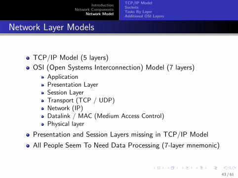
Network Layer Models
TCP/IP Model (5 layers)
OSI (Open Systems Interconnection) Model (7 layers)
ApplicationPresentation LayerSession LayerTransport (TCP / UDP)Network (IP)Datalink / MAC (Medium Access Control)Physical layer
Presentation and Session Layers missing in TCP/IP Model
All People Seem To Need Data Processing (7-layer mnemonic)
43 / 61

IntroductionNetwork Components
Network Model
TCP/IP ModelSocketsTasks By LayerAdditional OSI Layers
Physical Layer
Hardware for physically carrying data
Over wires, or wireless links
modems, Ethernet/Wifi card, etc.
44 / 61

IntroductionNetwork Components
Network Model
TCP/IP ModelSocketsTasks By LayerAdditional OSI Layers
Data Link Layer
send a packet of bits from one computer to another when adirect connection exists between the computers
Depends on the nature of the physical medium used
Two broad categories depending on if the physical medium isshared.
For shared media DL protocols includes protocols for MediumAccess Control (MAC).
Every computer that shares the physical medium should have aunique MAC layer addressContention for channel access needs to be addressed
45 / 61

IntroductionNetwork Components
Network Model
TCP/IP ModelSocketsTasks By LayerAdditional OSI Layers
Network Layer
Provide a virtual link between two computers.
To send a packet from one computer to another
A unique network address for every computer
Routers relay packets over multiple hops
Internet protocol (IP) — every computer has a unique IPaddress
46 / 61

IntroductionNetwork Components
Network Model
TCP/IP ModelSocketsTasks By LayerAdditional OSI Layers
Application and Transport Layer
Protocols for applications/processes running on differentcomputers to communicate with each other
Rely on the “virtual link” facilitated by the lower layers.
47 / 61

IntroductionNetwork Components
Network Model
TCP/IP ModelSocketsTasks By LayerAdditional OSI Layers
Application Layer
Client-server model
(Client establishes a connection with the server)Client sends a requestServer responds(Close connection)
Some applications: E-mail, WWW, IM, FTP, File sharing, · · ·
48 / 61

IntroductionNetwork Components
Network Model
TCP/IP ModelSocketsTasks By LayerAdditional OSI Layers
Transport Layer
Provides a “reliable connection” between processes running ondifferent computers
Takes care of many low-level details for creating, maintainingand closing connections
Different processes running on a computer differentiated byunique process addresses (port numbers)
49 / 61

IntroductionNetwork Components
Network Model
TCP/IP ModelSocketsTasks By LayerAdditional OSI Layers
Application Developer View of Internet
Every computer connected to the Internet has a unique IPaddress
Corresponding to each IP address, there may be manyapplication processes willing to accept connection requestsat a specific port number.
Servers listen — wait for connection requests
Clients initiate connection requests.
Once a connection is established, both client and server cansend and receive (any number of) bytes.
Connections can then be closed.
50 / 61

IntroductionNetwork Components
Network Model
TCP/IP ModelSocketsTasks By LayerAdditional OSI Layers
Client Server Applications
Server
0 Listen at some port number
2 Accept connection request
4 Process Query
5 Send Response
7/8 Close Connection
Client
1 Request Connection
3 Send Query
6 Receive response
7/8 Close connection
51 / 61

IntroductionNetwork Components
Network Model
TCP/IP ModelSocketsTasks By LayerAdditional OSI Layers
Addressing servers and Clients
Client needs to know IP address and port number of theserver.
Usually clients know only the domain name (for e.g.,yahoo.com)
DNS (domain name system/service) — an application thattranslates domain names to IP addresses (like 411 Directoryservice);
Port number depends on the type of application (standardport numbers)
Connection request made by specifying IP address and portnumber of the server,
Also conveys IP address and port number used by the client.
52 / 61

IntroductionNetwork Components
Network Model
TCP/IP ModelSocketsTasks By LayerAdditional OSI Layers
Sockets and Socket Programming
Software library for network application development;
Sockets are similar to file handles
File handles bound to a file name (and path); Sockets boundto socket address;
Socket address has two components — an IP address and aport number
Two types of sockets - TCP (transport control protocol) andUDP (user datagram protocol)
TCP sockets can be connected.
The socket library provides various system calls like socket(),bind(), listen(), connect(), accept(), send(), recv(), close()
53 / 61

IntroductionNetwork Components
Network Model
TCP/IP ModelSocketsTasks By LayerAdditional OSI Layers
Socket (System) Calls
sd = socket(OPTIONS). Creates a socket. sd is a handleto the socket.
bind(sd,FROMADDRESS) (local socket address).
listen()
connect(sd,TOADDRESS) (remote socket address).
sd = accept(sd) (accept() returns a connected socket)
send(sd,buffer, num bytes).
recv(sd,buffer, num bytes).
close(sd).
These functions are the interfaces provided by the transportlayer (to the application layer above).
54 / 61

IntroductionNetwork Components
Network Model
TCP/IP ModelSocketsTasks By LayerAdditional OSI Layers
Transport Layer Tasks
Establish connections; reliable delivery of application data;differentiating between different communication instancesusing port numbers;
Break up application data into message chunks; add aTRANSPORT header to each message (Transport packet =TRANSPORT header + application message)
Send / receive transport packets to / from the network layer.
Flow control: what happens if the sender has a highbandwidth connection and the receiver has a low bandwidthconnection?
Congestion control (helps NL in this process)
55 / 61

IntroductionNetwork Components
Network Model
TCP/IP ModelSocketsTasks By LayerAdditional OSI Layers
AL and TL
Trans. Hdr (1546,80, flags, sequence/ack no. . . . )
Net. Hdr (120.5.246.47,201.234.56.78, . . . )
(Client) AL; port 1546 (Server) AL; port 80
Transport Layer Transport Layer
NL; IP 120.5.246.47 NL; IP 201.234.56.78
App. Data
Trans. Packet = Trans Hdr + App Data
Net. Packet = Net Hdr + Trans Packet
56 / 61
IntroductionNetwork Components
Network Model
TCP/IP ModelSocketsTasks By LayerAdditional OSI Layers
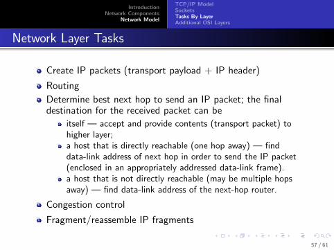
Network Layer Tasks
Create IP packets (transport payload + IP header)
Routing
Determine best next hop to send an IP packet; the finaldestination for the received packet can be
itself — accept and provide contents (transport packet) tohigher layer;a host that is directly reachable (one hop away) — finddata-link address of next hop in order to send the IP packet(enclosed in an appropriately addressed data-link frame).a host that is not directly reachable (may be multiple hopsaway) — find data-link address of the next-hop router.
Congestion control
Fragment/reassemble IP fragments
57 / 61
IntroductionNetwork Components
Network Model
TCP/IP ModelSocketsTasks By LayerAdditional OSI Layers
DL and PL
DL / MAC layer
Enclose IP packet (to be sent to next hop) in a DL / MACframeIP packet may be split into multiple smaller chunks (if the DLcannot handle large payloads)MAC Frame = MAC Header + Payload (IP packet) + footer+ framing flags at either end.MAC header includes MAC addresses of sender and receiver(one hop away from sender)MAC/DL footer for cyclic redundancy checks (CRC) — forerror detection.Provide the MAC frame to hardware (Ethernet card, modem)using interfaces to the hardware (drivers)
Physical Layer: Convert bits to electrical/electromagneticsignals and send them over the link
58 / 61

IntroductionNetwork Components
Network Model
TCP/IP ModelSocketsTasks By LayerAdditional OSI Layers
Layer Hierarchy
ALData Packet
TL
NL
DL
PLConversion to Electrical Signals
DataTH TH TH TH
TH DataNH
DH NH TH Data
Destination Port Origin IP Origin Port
Next Stop DL Address Origin DL Address
Destination IP
TH − TCP HEADER, NH − IP HEADER, DH − MAC HEADER
59 / 61

IntroductionNetwork Components
Network Model
TCP/IP ModelSocketsTasks By LayerAdditional OSI Layers
Presentation Layer
Syntax and semantics of information transmitted
The same sequence of bytes can have different interpretationsin different machines/CPUs — Big-endian vs little-endian
All machines need to agree on some byte order (forrepresenting 32-bit IP address and 16-bit port numbers)
Network order, host order
For TCP/IP translations are provided by some helperfunctions - htons(), htonl(), ntohs(), ntohl() included in thesocket library.
60 / 61

IntroductionNetwork Components
Network Model
TCP/IP ModelSocketsTasks By LayerAdditional OSI Layers
Session Layer
Establishing sessions
Dialog control (who goes next?)
Synchronization (continue seamlessly from previousconnection)
In TCP/IP model, dialog control and synchronization is theresponsibility of the application layer
Examples?
61 / 61