Data Communication Principles - Mississippi State...
198
Outline Networks and Components Layered Model Data Communication Channels Delays and Switching Reliable Data Transfer Data Communication Principles Mahalingam Ramkumar Mississippi State University, MS January 22, 2018 Ramkumar CSE 4153 / 6153
Transcript of Data Communication Principles - Mississippi State...

OutlineNetworks and Components
Layered ModelData Communication Channels
Delays and SwitchingReliable Data Transfer
Data Communication Principles
Mahalingam RamkumarMississippi State University, MS
January 22, 2018
Ramkumar CSE 4153 / 6153

OutlineNetworks and Components
Layered ModelData Communication Channels
Delays and SwitchingReliable Data Transfer
Data Communication Networks
Data (bits)
Communication (conveyance of data)
Network (the facilitator)
Bits (packets) exchanged between computers;
The network is the Internet
2 / 179

OutlineNetworks and Components
Layered ModelData Communication Channels
Delays and SwitchingReliable Data Transfer
Grading Policy
50% Take Home Activities (Multiple choice / Quantitative/Short essays)
25% Final Exam
15% Socket Programming Assignments
10% Participation
3 / 179

OutlineNetworks and Components
Layered ModelData Communication Channels
Delays and SwitchingReliable Data Transfer
Expectations
For advanced Juniors, Seniors and Graduate students
Text-book - “Computer Networking: A Top-Down Approach,”by Kurose and Ross
Self-learning required:
socket programmingWireshark, tcpdump, etc., for capturing and analyzing networkpackets
4 / 179

OutlineNetworks and Components
Layered ModelData Communication Channels
Delays and SwitchingReliable Data Transfer
A Systems Course
System: a collection of entities working together towards acommon purpose/goals.
What are the goals (of the Internet)?
How does each component work? How do they work together?
Only course where you actually study a large, complex,distributed system
Can we make things better? Where are we headed?
5 / 179

OutlineNetworks and Components
Layered ModelData Communication Channels
Delays and SwitchingReliable Data Transfer
Course Outline
Overview of the Internet;
Data Communication Principles
Internet Practices
6 / 179

OutlineNetworks and Components
Layered ModelData Communication Channels
Delays and SwitchingReliable Data Transfer
Data Communication Principles
Communication Theory
Delays and Switching
Reliable Data Transmission
Error Detection/Correction
ARQ Protocols
Shared media
7 / 179

OutlineNetworks and Components
Layered ModelData Communication Channels
Delays and SwitchingReliable Data Transfer
Internet Practices
Protocols in different Internet layers
DL/MAC layer protocolsIP protocolTCP and UDPSocket Library and Application Protocols
8 / 179

OutlineNetworks and Components
Layered ModelData Communication Channels
Delays and SwitchingReliable Data Transfer
Why Digital?
More Efficient
eg., analog vs digital TV
Great equalizer — for transmission/reception, storage andprocessing
Does not matter if data is video, audio, image or document, oranything else
Better suited for long range transmission
Can use repeatersWhy is this not suitable for analog transmission?
9 / 179

OutlineNetworks and Components
Layered ModelData Communication Channels
Delays and SwitchingReliable Data Transfer
Terminology
Protocol (rigid rules/steps to be followed)
Bit-rate (Kbps, Mbps, Gbps)
Storage (KB, MB, GB, TB)
Useful to be comfortable with powers of 2
210 = 1024 ≈ 1000, 220 ≈ 1, 000, 000 (million),230 ≈ 1, 000, 000, 000 (billion)
IP (Internet Protocol) address, 32-bit unsigned number
For convenience represented as 4 1-byte (8-bit) numbers(each in the range 0 to 255)
Example, 129.36.42.207.
10 / 179

OutlineNetworks and Components
Layered ModelData Communication Channels
Delays and SwitchingReliable Data Transfer
Functional OrganizationPhysical Organization
Network Components
Hosts (users of the network) & Network Infrastructure(provider)
Postal Network: sender receiver; USPS
Telephone network: caller and callee (subscribers); Telephonecompanies (network)
Mobile Telephone: subscribers; service provider.
11 / 179

OutlineNetworks and Components
Layered ModelData Communication Channels
Delays and SwitchingReliable Data Transfer
Functional OrganizationPhysical Organization
Internet Components
Network Hosts & Network Infrastructure
Host computers: Clients and servers
Infrastructure: Internet service providers (ISP)
ISPs in different tiers. Tier III ISPs rely on Tier II ISPs, andso on
Tier I ISPs are “Backbone operators.”
Some large users (eg., Google, Netflix, Amazon, Yahoo) mayconnect directly to Tier I ISPs.
Infrastructure components: Routers and Links (fiber, twistedpair, coax, wireless, satellite)
12 / 179

OutlineNetworks and Components
Layered ModelData Communication Channels
Delays and SwitchingReliable Data Transfer
Functional OrganizationPhysical Organization
Classical Telephone Network
Telephones connected by a wire (twisted pair copper) to alocal switching office (up to 10000 phones)
Several local switching offices are connected to an areaswitching office (up to 1000 LSO per ASO)
Area switching offices are interconnected (1000 ASOs)
Each wire (from a phone to a switching office) is associatedwith a unique (phone) number — eg. (662) 323-1234
area code 662 identifies area switching office323 identifies local switching office;every wire terminating at switching office 323 has a uniquefour digit number xxxx.
13 / 179

OutlineNetworks and Components
Layered ModelData Communication Channels
Delays and SwitchingReliable Data Transfer
Functional OrganizationPhysical Organization
Classical Telephone Network
When the telephone receiver is lifted off the base the wire isactivated (user hears a dial tone)
User dials a destination number
this is an instruction to the LSO to establish a path betweenthe two phones
662 323 5678 ↔ 301 506 7259
662 323 5678 ↔ LSO 323 ↔ ASO 662 ↔ ASO 301 ↔ LSO506 ↔ 301 506 7259
the path can be used for sending electrical signals between thetwo phones.
14 / 179

OutlineNetworks and Components
Layered ModelData Communication Channels
Delays and SwitchingReliable Data Transfer
Functional OrganizationPhysical Organization
Classical Telephone Network
Mouthpiece converts sound vibrations (pressure) to anelectrical signal
Electrical signals conveyed over the wire (at the speed of lightin copper) to the telephone at the other end.
At the receiver, earpiece converts electrical signals to pressurevibrations (sound)
Replacing the telephone on the hook terminates theconnection.
Telephone company keeps a record of the destination andduration of your call (for billing purposes).
15 / 179

OutlineNetworks and Components
Layered ModelData Communication Channels
Delays and SwitchingReliable Data Transfer
Functional OrganizationPhysical Organization
Postal Network
Users address mail/packages and drop them into boxes.
Picked up by postal carriers
Depending on the final destination the mail/package may berouted over several hops
Possibly different modes of transportation at each hop (foot,bicycle, van, train, airplane, · · · )Mail finally delivered to the destination address.
Postal network uses packet switching. Telephone networkuses circuit switching
16 / 179
OutlineNetworks and Components
Layered ModelData Communication Channels
Delays and SwitchingReliable Data Transfer
Functional OrganizationPhysical Organization
Postal Network vs Telephone Network
Postal network uses packet switching.
Telephone network uses circuit switching.
17 / 179
OutlineNetworks and Components
Layered ModelData Communication Channels
Delays and SwitchingReliable Data Transfer
Functional OrganizationPhysical Organization
The Internet at a Glance
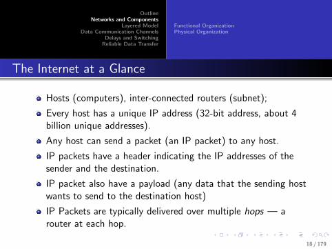
Hosts (computers), inter-connected routers (subnet);
Every host has a unique IP address (32-bit address, about 4billion unique addresses).
Any host can send a packet (an IP packet) to any host.
IP packets have a header indicating the IP addresses of thesender and the destination.
IP packet also have a payload (any data that the sending hostwants to send to the destination host)
IP Packets are typically delivered over multiple hops — arouter at each hop.
18 / 179
OutlineNetworks and Components
Layered ModelData Communication Channels
Delays and SwitchingReliable Data Transfer
Functional OrganizationPhysical Organization
Routers and Links
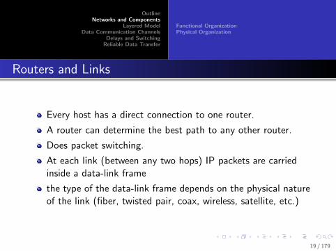
Every host has a direct connection to one router.
A router can determine the best path to any other router.
Does packet switching.
At each link (between any two hops) IP packets are carriedinside a data-link frame
the type of the data-link frame depends on the physical natureof the link (fiber, twisted pair, coax, wireless, satellite, etc.)
19 / 179
OutlineNetworks and Components
Layered ModelData Communication Channels
Delays and SwitchingReliable Data Transfer
Functional OrganizationPhysical Organization
Postal Network vs Internet
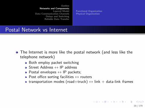
The Internet is more like the postal network (and less like thetelephone network)
Both employ packet switchingStreet Address ↔ IP addressPostal envelopes ↔ IP packets;Post office sorting facilities ↔ routerstransportation modes (road+truck) ↔ link + data-link frames
20 / 179

OutlineNetworks and Components
Layered ModelData Communication Channels
Delays and SwitchingReliable Data Transfer
Functional OrganizationPhysical Organization
Postal Network vs Internet
Postal envelopes carry a letter from sender to receiver; IPpackets carry an application message;different transportation mechanisms over each hop
truck over road, train over rails, ships over oceans/waterwaysetc.different types of data-link frames over different types ofphysical layers;Ethernet over twisted pair, Wireless Ethernet over air, ALOHAover satellite links, FTTH over fiber, etc.
The main difference is the speed — IP packets travel at thespeed of light
The Internet is postal network on steroids!
21 / 179

OutlineNetworks and Components
Layered ModelData Communication Channels
Delays and SwitchingReliable Data Transfer
Functional OrganizationPhysical Organization
Virtual Link Between Hosts
The speed of exchanges motivates sophisticated Internetbased applications
Applications running on hosts use the Internet tocommunicate with applications running on other hosts(possibly even at the other side of the globe)
From the perspective of applications, the Internet enables avirtual link between hosts.
22 / 179

OutlineNetworks and Components
Layered ModelData Communication Channels
Delays and SwitchingReliable Data Transfer
Functional OrganizationPhysical Organization
Functional Organization — Internet Layers
Application Layer (AL)
Transport Layer (TL)
Network Layer (NL)
Data-Link Layer (DL)
Physical Layer (PL)
Each layer has a specific function.
Components in one layer can be modified without affectingother layers.
All Top Notch Donut Places (useful? mnemonic)
23 / 179

OutlineNetworks and Components
Layered ModelData Communication Channels
Delays and SwitchingReliable Data Transfer
Functional OrganizationPhysical Organization
Lower and Upper Layers
The two lower layers (PL and DL) are necessary for thefunctioning of the NL (to create a virtual link between hosts)
The two upper layers (TL and AL) are required to use thevirtual link
“Sockets” in upper layers are bound to a specific transportport number and a specific network (IP) address
“Network interfaces” in lower layers are bound to a specific IPaddress and a DL address
24 / 179

OutlineNetworks and Components
Layered ModelData Communication Channels
Delays and SwitchingReliable Data Transfer
Functional OrganizationPhysical Organization
Sockets and Network Interfaces
Physical
Data Link
Network
Transport
Application
Net. Interfaces
Sockets
Transport layer managesmultiple sockets
Each socket (bound to a portnumber and IP address)corresponds to an application.
Network layer may manageseveral network interfaces
Each interface (bound to an IPaddress and data-link address)has its own lower layers(datalink+physical)
25 / 179

OutlineNetworks and Components
Layered ModelData Communication Channels
Delays and SwitchingReliable Data Transfer
Functional OrganizationPhysical Organization
Lower Layers
Physical Layer — convert data-link frames to electricalsignals for delivery over a physical medium
Data-link Layer — preparing data-link frames (which carryIP packets) for efficient utilization of the physical layer(physical layer could be unreliable)
Network layer — determines how IP packets will need to berouted, depending on the destination IP address
26 / 179

OutlineNetworks and Components
Layered ModelData Communication Channels
Delays and SwitchingReliable Data Transfer
Functional OrganizationPhysical Organization
Upper Layers
Transport Layer — converts the unreliable “virtual link”between two hosts (thanks to lower layers) into a reliableconnection, to carry application messages
Application Layer — uses the reliable connection to sendapplication messages (between an application running on onehost and an application running on another host)
27 / 179

OutlineNetworks and Components
Layered ModelData Communication Channels
Delays and SwitchingReliable Data Transfer
Functional OrganizationPhysical Organization
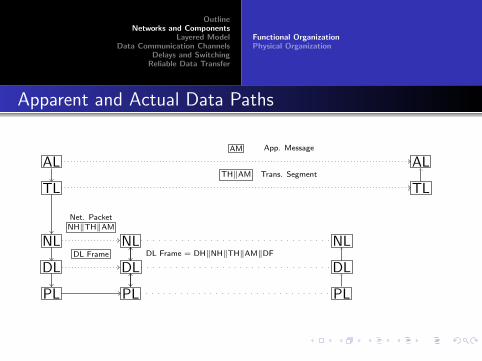
Apparent and Actual Data Paths
AL ALAM App. Message
TL TLTH‖AM Trans. Segment
NL NLNH‖TH‖AMNet. Packet
DL DLDL Frame DL Frame = DH‖NH‖TH‖AM‖DF
PL PL
NL
DL
PL
NL
DL
PL
Virtual Link
28 / 179

OutlineNetworks and Components
Layered ModelData Communication Channels
Delays and SwitchingReliable Data Transfer
Functional OrganizationPhysical Organization
Apparent and Actual Data Paths
AL ALAM App. Message
TL TLTH‖AM Trans. Segment
NL NLNH‖TH‖AMNet. Packet
DL DLDL Frame DL Frame = DH‖NH‖TH‖AM‖DF
PL PL
NL
DL
PL
NL
DL
PL
Virtual Link
28 / 179

OutlineNetworks and Components
Layered ModelData Communication Channels
Delays and SwitchingReliable Data Transfer
Functional OrganizationPhysical Organization
Layers in Switches and Routers
29 / 179

OutlineNetworks and Components
Layered ModelData Communication Channels
Delays and SwitchingReliable Data Transfer
Functional OrganizationPhysical Organization
Physical Organization
Several hosts connected to a router in the same local areanetwork (LAN)
LANs may be interconnected by routers to form smallnetworks
small networks may be interconnected to form larger networks(for example, an organization)
organizations connect to an Internet Service Provider (ISP)
ISPs may form several tiers
lower tier ISPs connect to higher tier ISPs
ISPs at the highest tier interconnected by the Internetbackbones.
30 / 179

OutlineNetworks and Components
Layered ModelData Communication Channels
Delays and SwitchingReliable Data Transfer
Functional OrganizationPhysical Organization
Interconnection of Networks
R1
R2
R3
R4
R5
R6
R7
R1
R2
R3
R4
R5R6
R7
ISP
31 / 179

OutlineNetworks and Components
Layered ModelData Communication Channels
Delays and SwitchingReliable Data Transfer
Functional OrganizationPhysical Organization
Interconnection of Networks
R1
R2
R3
R4
R5
R6
R7
R1
R2
R3
R4
R5R6
R7
ISP
31 / 179

OutlineNetworks and Components
Layered ModelData Communication Channels
Delays and SwitchingReliable Data Transfer
Functional OrganizationPhysical Organization
Interconnection of Networks
R1
R2
R3
R4
R5
R6
R7
R1
R2
R3
R4
R5R6
R7
ISP
31 / 179

OutlineNetworks and Components
Layered ModelData Communication Channels
Delays and SwitchingReliable Data Transfer
Functional OrganizationPhysical Organization
Interconnection of Networks
R1
R2
R3
R4
R5
R6
R7
R1
R2
R3
R4
R5R6
R7
ISP
31 / 179

OutlineNetworks and Components
Layered ModelData Communication Channels
Delays and SwitchingReliable Data Transfer
Functional OrganizationPhysical Organization
Interconnection of ISPs
i1
i2
i3 i4
i5
i6
i7
i8i9
i0
Tier II
Tier III
I1
I2
I3 I4
I5
I6
I7
I8I9
Ia
Tier IB1
B2
B3
B4
B5
B6
B7
B8
32 / 179

OutlineNetworks and Components
Layered ModelData Communication Channels
Delays and SwitchingReliable Data Transfer
Functional OrganizationPhysical Organization
IP Addresses
32-bit unsigned number,
for example, 10101110 01001000 11000010 11001001
which is 2,924,004,041
more conveniently represented as 174.72.194.201
About 4 billion unique addresses
Another example, 130.18.205.15 is actually
10000010 00010010 11001101 00001111 = 2, 182, 270, 223 (1)
33 / 179

OutlineNetworks and Components
Layered ModelData Communication Channels
Delays and SwitchingReliable Data Transfer
Functional OrganizationPhysical Organization
IP Address Chunks
Typically, consecutive IP addresses assigned to hosts in thesame LANFor example, a LAN with less than 128 (but greater than 64)computers can be assigned addresses 130.18.205.0 to130.18.205.127, which can all be collectively represented as
10000010 00010010 11001101 0xxxxxxx (2)
First 32-7=25 bits are the same in all such addressesA short from for representing such collection is130.18.205.0/25 (starting address, and the number ofcommon bits for all addresses in the chunk).IP Prefix notation (to represent a chunk of 2r consecutiveaddresses, where r is an integer).
34 / 179

OutlineNetworks and Components
Layered ModelData Communication Channels
Delays and SwitchingReliable Data Transfer
Functional OrganizationPhysical Organization
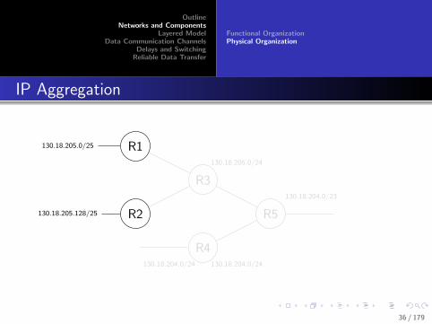
Aggregating IP Prefixes
Assume an adjacent LAN has addresses in the range130.18.205.128 to 130.18.205.255
Or prefix 130.18.205.128/25
10000010 00010010 11001101 1xxxxxxx (3)
130.18.205.0/25 and 130.18.205.128/25 can be consolidatedas 130.18.205.0/24, or
10000010 00010010 11001101 xxxxxxxx (4)
35 / 179
OutlineNetworks and Components
Layered ModelData Communication Channels
Delays and SwitchingReliable Data Transfer
Functional OrganizationPhysical Organization
IP Aggregation
130.18.205.0/25
130.18.205.128/25
R1
R2
R3
130.18.205.0/24
R4130.18.204.0/24 130.18.204.0/24
R5
130.18.204.0/23
36 / 179

OutlineNetworks and Components
Layered ModelData Communication Channels
Delays and SwitchingReliable Data Transfer
Functional OrganizationPhysical Organization
IP Aggregation
130.18.205.0/25
130.18.205.128/25
R1
R2
R3
130.18.205.0/24
R4130.18.204.0/24 130.18.204.0/24
R5
130.18.204.0/23
36 / 179

OutlineNetworks and Components
Layered ModelData Communication Channels
Delays and SwitchingReliable Data Transfer
Functional OrganizationPhysical Organization
IP Aggregation
130.18.205.0/25
130.18.205.128/25
R1
R2
R3
130.18.205.0/24
R4130.18.204.0/24 130.18.204.0/24
R5
130.18.204.0/23
36 / 179

OutlineNetworks and Components
Layered ModelData Communication Channels
Delays and SwitchingReliable Data Transfer
Functional OrganizationPhysical Organization
IP Aggregation
130.18.205.0/25
130.18.205.128/25
R1
R2
R3
130.18.205.0/24
R4130.18.204.0/24 130.18.204.0/24
R5
130.18.204.0/23
36 / 179

OutlineNetworks and Components
Layered ModelData Communication Channels
Delays and SwitchingReliable Data Transfer
Functional OrganizationPhysical Organization
Autonomous Systems
The Internet is an interconnection of autonomous systems(AS)
ASes advertise IP prefixes to other ASes
Every independent organization need not be an AS
An AS may include any number of networks / organizations.
What is the difference between an organizational network andan AS?
37 / 179
OutlineNetworks and Components
Layered ModelData Communication Channels
Delays and SwitchingReliable Data Transfer
Functional OrganizationPhysical Organization
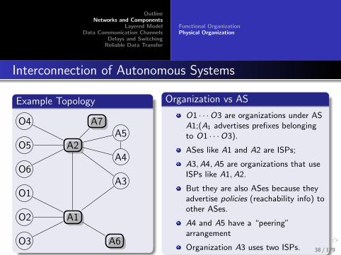
Interconnection of Autonomous Systems
Example Topology
O1
O2
O3
A1
O4
O5
O6
A2
A3
A4
A5
A6
A7
Organization vs AS
O1 · · ·O3 are organizations under ASA1;(A1 advertises prefixes belongingto O1 · · ·O3).
ASes like A1 and A2 are ISPs;
A3,A4,A5 are organizations that useISPs like A1,A2.
But they are also ASes because theyadvertise policies (reachability info) toother ASes.
A4 and A5 have a “peering”arrangement
Organization A3 uses two ISPs. 38 / 179

OutlineNetworks and Components
Layered ModelData Communication Channels
Delays and SwitchingReliable Data Transfer
TCP/IP Model
Network Layer Models
TCP/IP Model (5 layers)
OSI (Open Systems Interconnection) Model (7 layers)
ApplicationPresentation LayerSession LayerTransport (TCP / UDP)Network (IP)Datalink / MAC (Medium Access Control)Physical layer
Presentation and Session Layers missing in TCP/IP Model
All People Seem To Need Data Processing (7-layer mnemonic)
39 / 179
OutlineNetworks and Components
Layered ModelData Communication Channels
Delays and SwitchingReliable Data Transfer
TCP/IP Model
Physical Layer
Hardware for physically carrying data
Over wires, or wireless links
modems, Ethernet/Wifi card, etc.
40 / 179

OutlineNetworks and Components
Layered ModelData Communication Channels
Delays and SwitchingReliable Data Transfer
TCP/IP Model
Data Link Layer
send a packet of bits from one computer to another when adirect connection exists between the computers
Depends on the nature of the physical medium used
Two broad categories depending on if the physical medium isshared.
For shared media DL protocols includes protocols for MediumAccess Control (MAC).
Every computer that shares the physical medium should have aunique MAC layer addressContention for channel access needs to be addressed
41 / 179

OutlineNetworks and Components
Layered ModelData Communication Channels
Delays and SwitchingReliable Data Transfer
TCP/IP Model
Network Layer
Provide a virtual link between two computers.
To send a packet from one computer to another
A unique network address for every computer
Routers relay packets over multiple hops
Internet protocol (IP) — every computer has a unique IPaddress
42 / 179

OutlineNetworks and Components
Layered ModelData Communication Channels
Delays and SwitchingReliable Data Transfer
TCP/IP Model
Application and Transport Layer
Protocols for applications/processes running on differentcomputers to communicate with each other
Rely on the “virtual link” facilitated by the lower layers.
43 / 179

OutlineNetworks and Components
Layered ModelData Communication Channels
Delays and SwitchingReliable Data Transfer
TCP/IP Model
Application Layer
Client-server model
(Client establishes a connection with the server)Client sends a requestServer responds(Close connection)
Some applications: E-mail, WWW, IM, FTP, File sharing, · · ·
44 / 179

OutlineNetworks and Components
Layered ModelData Communication Channels
Delays and SwitchingReliable Data Transfer
TCP/IP Model
Transport Layer
Provides a “reliable connection” between processes running ondifferent computers
Takes care of many low-level details for creating, maintainingand closing connections
Different processes running on a computer differentiated byunique process addresses (port numbers)
45 / 179
OutlineNetworks and Components
Layered ModelData Communication Channels
Delays and SwitchingReliable Data Transfer
Data RateTransmission MediaModulationMultiplexing
Fundamental Factors
Channel bandwidth H Hz
Signal power S Watts
Noise power N Watts
46 / 179

OutlineNetworks and Components
Layered ModelData Communication Channels
Delays and SwitchingReliable Data Transfer
Data RateTransmission MediaModulationMultiplexing
Channel Capacity R
Achievable bit-rate R
Shannon’s Capacity Limit
R = H log2(1 + S/N) bps. (5)
47 / 179

OutlineNetworks and Components
Layered ModelData Communication Channels
Delays and SwitchingReliable Data Transfer
Data RateTransmission MediaModulationMultiplexing
S/N in Decibels (dB)
Signal to Noise Ratio (SNR)
Usually expressed in dB
(S/N)dB = 10log10(S/N)
20 dB → S/N = 100;
30 dB → S/N = 1000;
48 / 179

OutlineNetworks and Components
Layered ModelData Communication Channels
Delays and SwitchingReliable Data Transfer
Data RateTransmission MediaModulationMultiplexing
Example
What is the limit on achievable rate R in a channel withbandwidth 1 MHz and SNR 30 dB?
30dB → S/N = 1000
R = 1× 10⁶ × log2(1 + 1000) ≈ 1× 106 × 10 = 10Mbps (6)
To double the rate to 20 Mbps, we can
Double the bandwidth, orincrease SNR to 60 dB (or increase S/N ≈ 1 million)log2(1, 000, 000) ≈ 20
49 / 179

OutlineNetworks and Components
Layered ModelData Communication Channels
Delays and SwitchingReliable Data Transfer
Data RateTransmission MediaModulationMultiplexing
Shannon-Nyquist Sampling Theorem
Any signal “emerging” from a medium is band-width limited
Bandwidth - H hertz (cycles/sec)
A band-limited signal (limited to H Hz) can be uniquelyreconstructed from discrete samples taken at a rate 2H persecond
50 / 179

OutlineNetworks and Components
Layered ModelData Communication Channels
Delays and SwitchingReliable Data Transfer
Data RateTransmission MediaModulationMultiplexing
Shannon-Nyquist Capacity
Assume each sample can take V possible values
log2(V ) bits per sample
Nyquist capacity C = 2H log2(V )
No of distinct recognizable values V is determined by noise.
If noise is zero, V →∞, so C →∞Every medium has inherent noise
Even at absolute zero (0 Kelvin).
51 / 179

OutlineNetworks and Components
Layered ModelData Communication Channels
Delays and SwitchingReliable Data Transfer
Data RateTransmission MediaModulationMultiplexing
Transmission Media
Two basic types
Guided
Twisted pairCoaxial cablesFiber opticsMagnetic media
Unguided
52 / 179

OutlineNetworks and Components
Layered ModelData Communication Channels
Delays and SwitchingReliable Data Transfer
Data RateTransmission MediaModulationMultiplexing
Twisted Pair
Telephone cables
Any wire is an antenna...
Twisting substantially reduces interference
Waves from different twists cancel out
Number of twists per cm
Categories 3 (16MHz), 5 (100 MHz), 6 (250), and 7(600)
Ethernet cables
(a) (b)
53 / 179

OutlineNetworks and Components
Layered ModelData Communication Channels
Delays and SwitchingReliable Data Transfer
Data RateTransmission MediaModulationMultiplexing
Coaxial Cables
Up to 1 GHz
Twisted pair cables are catching up!
Better noise immunity than twisted pairs
Used for TV signals, cable TV ...
Copper core
Insulating material
Braided outer conductor
Protective plastic covering
54 / 179

OutlineNetworks and Components
Layered ModelData Communication Channels
Delays and SwitchingReliable Data Transfer
Data RateTransmission MediaModulationMultiplexing
Fiber Optics
Extremely high bandwidth
Single mode and multimode
Single mode fibers can handle upto 50GHz over 100km!
Total internal reflection.
Air/silica boundary
Light sourceSilica
Air
(a) (b)
β1 β2 β3
α1 α2 α3
55 / 179

OutlineNetworks and Components
Layered ModelData Communication Channels
Delays and SwitchingReliable Data Transfer
Data RateTransmission MediaModulationMultiplexing
Fiber vs Copper Wire
Weight vs bandwidth
Cost
Security
56 / 179

OutlineNetworks and Components
Layered ModelData Communication Channels
Delays and SwitchingReliable Data Transfer
Data RateTransmission MediaModulationMultiplexing
Electromagnetic Spectrum
100 102 104 106 108 1010 1012 1014 1016 1018 1020 1022 1024
Radio Microwave Infrared UV X-ray Gamma ray
f (Hz)
Visible light
104 105 106 107 108 109 1010 1011 1012 1013 1014 1015 1016
f (Hz)
Twisted pairCoax
Satellite
TV
Terrestrial microwave
Fiber
optics
MaritimeAM
radioFM
radio
Band LF MF HF VHF UHF SHF EHF THF
57 / 179

OutlineNetworks and Components
Layered ModelData Communication Channels
Delays and SwitchingReliable Data Transfer
Data RateTransmission MediaModulationMultiplexing
Allocation of Spectrum
ITU-R, FCCISM (Industrial, Scientific, Medical) Bands
Freq.
Bandwidth
902 MHz
928 MHz
26 MHz
2.4 GHz
2.4835 GHz
5.735 GHz
5.860 GHz
. . . . . .
. . . . . .83.5 MHz
125 MHz
58 / 179
OutlineNetworks and Components
Layered ModelData Communication Channels
Delays and SwitchingReliable Data Transfer
Data RateTransmission MediaModulationMultiplexing
Satellites
Geo-stationary (about 36,000 km)
Medium Earth Orbit (18,000 km, 6 hr orbits)
Low Earth Orbit (less than 1000 km)
Satellite vs Fiber
Remote / hostile areasPoint-to-point vs BroadcastMobile communications“Right of way” for laying cables
59 / 179
OutlineNetworks and Components
Layered ModelData Communication Channels
Delays and SwitchingReliable Data Transfer
Data RateTransmission MediaModulationMultiplexing
Modulation
Modulation: information signal + carrier signal → modulatedsignal
Speech signals have frequencies between 300 and 3000 HzSignals cannot propagate directly over all mediumsSpeech signals s(t) can be sent directly over a copper cable:but not over air or free-space“Carrier” signals are used to carry the “information” signals
Modulated signal transmitted over a medium
Demodulation: extracting information signal from themodulated signal
Types of modulation: Amplitude (AM), Phase (PM),Frequency (FM)
60 / 179

OutlineNetworks and Components
Layered ModelData Communication Channels
Delays and SwitchingReliable Data Transfer
Data RateTransmission MediaModulationMultiplexing
0 1 0 1 1 0 0 1 0 0 1 0 0
(a)
(b)
(c)
(d)
Phase changes61 / 179

OutlineNetworks and Components
Layered ModelData Communication Channels
Delays and SwitchingReliable Data Transfer
Data RateTransmission MediaModulationMultiplexing
Bandwidth of Modulated Signals
The same as the bandwidth of the “information” signal
The bandwidth is now around a “center” frequency — thefrequency of the “carrier”
Many signals can coexist simultaneously in the medium.
By using different carrier frequencies
62 / 179

OutlineNetworks and Components
Layered ModelData Communication Channels
Delays and SwitchingReliable Data Transfer
Data RateTransmission MediaModulationMultiplexing
Modulation for FAX/Dial-up Internet
Send bits over telephone cable using Modem (Modulator -Demodulator)
Cable meant for carrying voice signals between 300-3000 Hz
Amplitude + phase modulation - series of sinusoidal pulses
Modulator: Bits are chunked, represented using sinusoidalpulses
Demodulator: Convert received sinusoidal pulse to bits
Clipped sinusoid is the basic signal
Variations achieved by modifying amplitude and phase
Represented on a constellation diagram
63 / 179

OutlineNetworks and Components
Layered ModelData Communication Channels
Delays and SwitchingReliable Data Transfer
Data RateTransmission MediaModulationMultiplexing
QPSK, QAM-16, QAM-64
Quadrature Phase Shift keying (2 bits per sample), QuadratureAmplitude Modulation
270
(a)
90
0 180
270
(b)
90
0
270
(c)
90
0 180
64 / 179

OutlineNetworks and Components
Layered ModelData Communication Channels
Delays and SwitchingReliable Data Transfer
Data RateTransmission MediaModulationMultiplexing
Telephone/FAX Modem
Each pulse represents multiple bits
If we use 16 different types of pulses (eg., QAM 16) we cansend 4 bits per pulse (16 = 24)
Bit rate and Baud rate
Baud rate - number of sinusoidal pulses per secondFixed at 2400 for telephone linesBit rate = Baud rate x number of bits per pulseHow do we get 56 K with baud rate of 2400?
65 / 179

OutlineNetworks and Components
Layered ModelData Communication Channels
Delays and SwitchingReliable Data Transfer
Data RateTransmission MediaModulationMultiplexing
Trellis Coded Modulation
Add more bits per sampleAdd extra bits to each sample for error correctionV.32 (4+1, 32) - 9600 bps, V.32 bis (6 + 1, 128) 14,400 bpsV.34 - 28,800 bps, V.34 bis - 36,600 bps
270
(b)
90
270
(c)
90
0 180 0 180
66 / 179
OutlineNetworks and Components
Layered ModelData Communication Channels
Delays and SwitchingReliable Data Transfer
Data RateTransmission MediaModulationMultiplexing
Modern Modems
Full duplex - transmissions possible in both directions at thesame time
Half-duplex - Both directions, but not at the same time
Simplex - Only one direction
V.90, V.92 - full duplex
Dedicated uplink and downlink channel
56 kbps downlink, 33.6 kbps uplink (V.90)
48kbps uplink (V.92) + facility to detect incoming calls whileonline
67 / 179

OutlineNetworks and Components
Layered ModelData Communication Channels
Delays and SwitchingReliable Data Transfer
Data RateTransmission MediaModulationMultiplexing
Actual Capacity of a Telephone Line
50
40
20
30
10
00 1000 2000 3000 4000
Meters5000 6000
Mpb
s
68 / 179

OutlineNetworks and Components
Layered ModelData Communication Channels
Delays and SwitchingReliable Data Transfer
Data RateTransmission MediaModulationMultiplexing
ADSL
We have been sitting on a gold-mine!
Telephones filter out higher frequencies to suppress noise
1.1 MhZ spectrum divided into 256 channels - 4312 Hz each(DMT - Discrete Multitone)
First channel used for POTS (plain old telephone service)
Pow
er
Voice Upstream Downstream
256 4-kHz Channels
0 25 1100 kHz
69 / 179

OutlineNetworks and Components
Layered ModelData Communication Channels
Delays and SwitchingReliable Data Transfer
Data RateTransmission MediaModulationMultiplexing
ADSL Equipment
DSLAM
Splitter
Codec
Splitter
Telephone
To ISP
ADSL modem
Ethernet
Computer
Telephone line
Telephone company end office Customer premises
Voice switch
NID
70 / 179

OutlineNetworks and Components
Layered ModelData Communication Channels
Delays and SwitchingReliable Data Transfer
Data RateTransmission MediaModulationMultiplexing
Multiplexing and Demultiplexing
Multiplexing - many to one
Many signal mixed together to produce one signal. Themultiplexed signal is transmitted over a channel
Demultiplexing - one to many
Multiplexed signal is split into individual components
Types: FDM, TDM, CDM
71 / 179

OutlineNetworks and Components
Layered ModelData Communication Channels
Delays and SwitchingReliable Data Transfer
Data RateTransmission MediaModulationMultiplexing
Frequency division multiplexing (FDM)
Telephone - 4000Hz per channel (450 + 3100 + 450)
300 3100
Channel 3
Channel 2
Channel 1
1
1
1
Atte
nuat
ion
fact
or
64
Frequency (kHz)
(c)
Channel 1 Channel 3Channel 2
68 72
60 64
Frequency (kHz)
(b)
Frequency (Hz)
(a)
68 72
60
72 / 179

OutlineNetworks and Components
Layered ModelData Communication Channels
Delays and SwitchingReliable Data Transfer
Data RateTransmission MediaModulationMultiplexing
Wavelength Division Multiplexing (WDM)
Spectrum on the shared fiber
Pow
er
λ
Fiber 4 spectrum
Pow
er
λ
Fiber 3 spectrum
Pow
erλ
Fiber 2 spectrum
Pow
er
λ
λ1
λ1+λ2+λ3+λ4
Fiber 1 spectrum
Pow
er
λ
Fiber 1λ2
Fiber 2λ3
Fiber 3Combiner Splitter
Long-haul shared fiber
λ4
λ2
λ4
λ1
λ3Fiber 4
Filter
73 / 179

OutlineNetworks and Components
Layered ModelData Communication Channels
Delays and SwitchingReliable Data Transfer
Data RateTransmission MediaModulationMultiplexing
Time Division Multiplexing (TDM)
N signals, each having M samples per sec: NM interleavedsamples per secPOTS signal (speech or clipped sinusoids) sampled at 80001-byte samples per sec (64000 bps)T1 lines - 1.544 Mbps, 24 channels
Channel 1
Channel 2
Channel 3
Channel 4
Channel 24
193-bit frame (125 µsec)
7 Data bits per channel
per sample
Bit 1 is a framing code
Bit 8 is for signaling
0
1
74 / 179
OutlineNetworks and Components
Layered ModelData Communication Channels
Delays and SwitchingReliable Data Transfer
Data RateTransmission MediaModulationMultiplexing
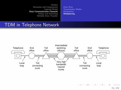
TDM in Telephone Network
Telephone
End
office
Toll
office
Intermediate switching office(s)
Telephone
End
office
Toll
office
Local loop
Toll connecting
trunk
Very high bandwidth
intertoll trunks
Toll connecting
trunk
Local loop
75 / 179

OutlineNetworks and Components
Layered ModelData Communication Channels
Delays and SwitchingReliable Data Transfer
Data RateTransmission MediaModulationMultiplexing
T1, T2, T3, T4
6 5 4 3 2 1 05 1
4 0
6 2
7 3
6:17:14:1
4 T1 streams in
1 T2 stream out
6.312 Mbps
T2
1.544 Mbps
T1
44.736 Mbps
T3
274.176 Mbps
T4
7 T2 streams in 6 T3 streams in
76 / 179

OutlineNetworks and Components
Layered ModelData Communication Channels
Delays and SwitchingReliable Data Transfer
Data RateTransmission MediaModulationMultiplexing
Code Division Multiple Access (CDMA)
TDM - different channels can overlap in frequencies, but notin time
FDM - no overlap in frequencies, overlap in time
CDMA - overlap in both time and frequency
Separable by orthogonality of codes
Two vectors are orthogonal if their inner-product is zero.
77 / 179

OutlineNetworks and Components
Layered ModelData Communication Channels
Delays and SwitchingReliable Data Transfer
Data RateTransmission MediaModulationMultiplexing
CDMA
Each bit is converted to a vector of chips
Different users assigned different orthogonal chip vectors
A user assigned vector x transmits x to send a one or −x tosend a zero
x .x = 1, x .(−x) = −1
x .y = 0 if y is orthogonal to x .
In practice difficult to obtain strict orthogonality
x .y can be made very small compared to 1
“Tolerable” interference with quasi-orthogonal sequences
CDMA is also more efficient (closer to Shannon’s limit)
78 / 179

OutlineNetworks and Components
Layered ModelData Communication Channels
Delays and SwitchingReliable Data Transfer
Data RateTransmission MediaModulationMultiplexing
Why CDMA?
If n chips per bit, then chip frequency n times higher thanbit-frequency
Energy to sent a bit spread over a larger frequency
Useful during war-time as transmission virtuallyindistinguishable for noise in any narrow band.
CDMA is also more efficient
Higher frequency and lower S/N takes us closer to Shannon’slimit
Capacity increases linearly with bandwidth (onlylogarithmically with S/N)
79 / 179
OutlineNetworks and Components
Layered ModelData Communication Channels
Delays and SwitchingReliable Data Transfer
RepeatersRound Trip TimeSwitchingPacket Switching
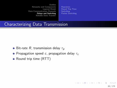
Characterizing Data Transmission
Bit-rate R, transmission delay τp
Propagation speed c , propagation delay τc
Round trip time (RTT)
80 / 179
OutlineNetworks and Components
Layered ModelData Communication Channels
Delays and SwitchingReliable Data Transfer
RepeatersRound Trip TimeSwitchingPacket Switching
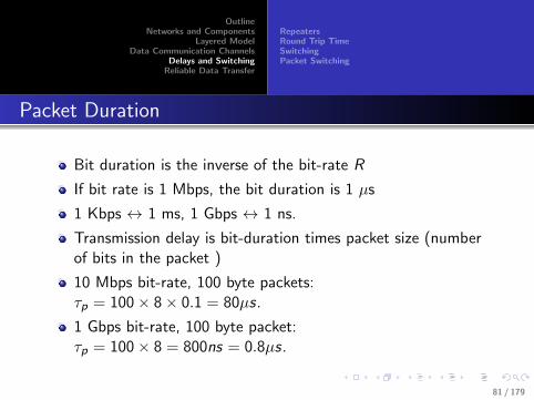
Packet Duration
Bit duration is the inverse of the bit-rate R
If bit rate is 1 Mbps, the bit duration is 1 µs
1 Kbps ↔ 1 ms, 1 Gbps ↔ 1 ns.
Transmission delay is bit-duration times packet size (numberof bits in the packet )
10 Mbps bit-rate, 100 byte packets:τp = 100× 8× 0.1 = 80µs.
1 Gbps bit-rate, 100 byte packet:τp = 100× 8 = 800ns = 0.8µs.
81 / 179
OutlineNetworks and Components
Layered ModelData Communication Channels
Delays and SwitchingReliable Data Transfer
RepeatersRound Trip TimeSwitchingPacket Switching
Total Delay
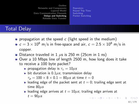
propagation at the speed c (light speed in the medium)c = 3× 10⁸ m/s in free-space and air, c = 2.5× 10⁸ m/s incopper.Distance traveled in 1 µs is 250 m (25cm in 1 ns)Over a 10 Mbps line of length 2500 m, how long does it taketo receive a 100 byte packet?
propagation delay is τc = 10µsbit duration is 0.1µs; transmission delayτp = 100× 8× 0.1 = 80µs at time t = 0leading edge of the packet sent at t = 0; trailing edge sent attime 80µsleading edge arrives at t = 10µs; trailing edge arrives att = 90µs
82 / 179

OutlineNetworks and Components
Layered ModelData Communication Channels
Delays and SwitchingReliable Data Transfer
RepeatersRound Trip TimeSwitchingPacket Switching
Total Delay
Pictorial Representation
t
τp
τc
distance
Total Delay
Total delay = Propagation delayτc + transmission delay τp
y axis is time
x axis represents distance
the slope represents speed ofpropagation
83 / 179

OutlineNetworks and Components
Layered ModelData Communication Channels
Delays and SwitchingReliable Data Transfer
RepeatersRound Trip TimeSwitchingPacket Switching
Repeaters
Used in long transmission lines
Converts electrical signals to bits, and back to electricalsignals, for retransmission
Repeaters placed strategically to ensure that signal strengthreceived at repeaters is strong enough to eliminate errors
The conversion process eliminates the effects of noise betweenrepeaters or between repeaters and end-points.
Repeaters introduce additional propagation delay
For a line of length 2500 m, with four repeaters (assume eachrepeater introduces a delay of 4µs) the propagation delay is10 + 4× 4 = 26µs.
84 / 179

OutlineNetworks and Components
Layered ModelData Communication Channels
Delays and SwitchingReliable Data Transfer
RepeatersRound Trip TimeSwitchingPacket Switching
Repeater Delay
Repeater Delay
Repeater Delay
Repeaters
repeaters do not affecttransmission delay
repeaters do not have to receivethe entire packet before startingthe conversion
Why not repeaters for analogcommunications?
85 / 179

OutlineNetworks and Components
Layered ModelData Communication Channels
Delays and SwitchingReliable Data Transfer
RepeatersRound Trip TimeSwitchingPacket Switching
Processing Delay
It takes a finite amount of time for the receiver to “process”the received packet (say, τr )
Data-link frames typically have a cyclic redundancy check(CRC) that will be verified (if inconsistent drop the corruptedpacket)
Routers will need time to look-up routing tables to determinethe best next hop.
There may also be queuing delay at routers
Routers may have several incoming and outgoing interfaces
A queue in an incoming interface may be stuck if the outgoinginterface for the packet at the head of the queue is busy.
86 / 179

OutlineNetworks and Components
Layered ModelData Communication Channels
Delays and SwitchingReliable Data Transfer
RepeatersRound Trip TimeSwitchingPacket Switching
Round Trip Time
Typically, every packet is acknowledged.
Round trip time (RTT) = trans. delay τp + propagation delayτc + processing delay τr + trans. delay for ack τ ′p + ackpropagation delay τc + ack processing delay τ ′r .
A decent approximation is RTT = 2× (τp + τc + τr )
What is the RTT over a 10 Mbps line of length 2500 m, if thepacket size (both sent and ACK) is 100 bytes, and theprocessing delay is 5 µs?
For the same length, packet size, and processing delay, what isthe RTT if the bit-rate is 1 Gbps?
87 / 179

OutlineNetworks and Components
Layered ModelData Communication Channels
Delays and SwitchingReliable Data Transfer
RepeatersRound Trip TimeSwitchingPacket Switching
Multi-hop Propagation
One way propagation delay for a channel with n hops isn(τc + τp + τr )
τp
τr
τc
88 / 179

OutlineNetworks and Components
Layered ModelData Communication Channels
Delays and SwitchingReliable Data Transfer
RepeatersRound Trip TimeSwitchingPacket Switching
A Simpler Representation of Delays
Representation
t
τc
τp
τr
τ
τ ′c
τ ′p
τ ′r
A
B
C
Simpler Representation
Forward path AB, reverse pathBC
τ = τc + τp + τr total forwardpath delay (τ ′ = τ ′c + τ ′p + τ ′rtotal reverse path delay)
In the simpler representationonly the lines AB and BC willbe depicted
Also often rotated by 90 degrees(time in X -axis)
89 / 179

OutlineNetworks and Components
Layered ModelData Communication Channels
Delays and SwitchingReliable Data Transfer
RepeatersRound Trip TimeSwitchingPacket Switching
Switching
Circuit Switching
Cut-through Switching
Store and Forward Switching
Circuit switching was used in Telephone networks (not anylonger)
90 / 179

OutlineNetworks and Components
Layered ModelData Communication Channels
Delays and SwitchingReliable Data Transfer
RepeatersRound Trip TimeSwitchingPacket Switching
Pkt vs Ckt Switching
τp
τr
τcτCS
τPS
τCS = 3τc + τp + τr
τPS = 3τc + 3τp + 3τr
For n hops: τPS = n(τc + τp + τr ), τPS = nτc + τp + τr91 / 179
OutlineNetworks and Components
Layered ModelData Communication Channels
Delays and SwitchingReliable Data Transfer
RepeatersRound Trip TimeSwitchingPacket Switching
Circuit Switching
Physical path established over multiple links
Circuit established at the physical layer level
Propagation delay is the sum of propagation delays over eachlink
Transmission delay is not affected
Was used in Telephone networks (not any longer)
92 / 179

OutlineNetworks and Components
Layered ModelData Communication Channels
Delays and SwitchingReliable Data Transfer
RepeatersRound Trip TimeSwitchingPacket Switching
Cut-through Switching
Begin forwarding a packet to next hop even before the entirepacket has been received
Leading bytes in the packet will indicate destination
Useful when look-up for destination can be accomplished veryfast
Delay for multi-hop propagation similar to the situation whenrepeaters are used.
93 / 179

OutlineNetworks and Components
Layered ModelData Communication Channels
Delays and SwitchingReliable Data Transfer
RepeatersRound Trip TimeSwitchingPacket Switching
Store and Forward or Packet Switching
Entire packet received before the packet can be sent to nexthop
delay at each hop is transmission delay+propagation delay+processing delay
total delay is the delays at each hop
packet duration has a significant impact on total delay.
Two types: Virtual Circuits and Datagram Switching
94 / 179
OutlineNetworks and Components
Layered ModelData Communication Channels
Delays and SwitchingReliable Data Transfer
RepeatersRound Trip TimeSwitchingPacket Switching
Datagram Switching
Datagram Subnet
A E F Process P2
LAN
Router
1
Carrier's equipment
Process P1
B
H1 H2
D
C
Packet
3
4
2
A –
B B
initially
C C
D B
E C
F C
Dest.
A –
B B
laterA's table
C C
D B
E B
F B
A A
B A
C's table
C –
D D
E E
F E
A C
B D
E's table
C C
D D
E –
F F
Line
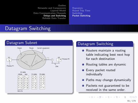
Datagram Switching
Routers maintain a routingtable indicating best next hopfor each destination
Routing tables are dynamic
Every packet routedindividually
Paths may change dynamically
Packets not guaranteed to bereceived in the same order.
95 / 179

OutlineNetworks and Components
Layered ModelData Communication Channels
Delays and SwitchingReliable Data Transfer
RepeatersRound Trip TimeSwitchingPacket Switching
Virtual Circuit Switching
VC Subnet
E FProcess P2
LAN
Router
1
Carrier's equipment
Process P1
Process P3
B
H1
H3
H2
D
C
3
42
H1 1
H3 1
C 1
C 2
A's table
A 1
A 2
E 1
E 2
C's table
C 1
C 2
F 1
F 2
E's table
A
In Out
Virtual Circuit
A path is established beforeeven the first packet can besent
Path accepted by all routers inthe path
Packets marked with a pathidentifier
Path identifier helps the routerdetermine how to forward thenext packet
Size of routing tables in arouter depends on number ofactive paths through therouter.
96 / 179
OutlineNetworks and Components
Layered ModelData Communication Channels
Delays and SwitchingReliable Data Transfer
RepeatersRound Trip TimeSwitchingPacket Switching
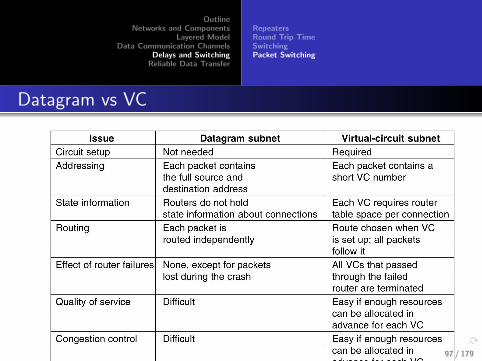
Datagram vs VC
97 / 179

OutlineNetworks and Components
Layered ModelData Communication Channels
Delays and SwitchingReliable Data Transfer
RepeatersRound Trip TimeSwitchingPacket Switching
Connectionless vs Connection-Oriented
Connectionless: Snail mail, telegram, etc.
Establishing connections makes the job of end points easier.
Circuit switching established a physical layer connection
Virtual circuits are established at the network layer level
In datagram-routing connection can be established at a higherlevel (transport layer).
98 / 179

OutlineNetworks and Components
Layered ModelData Communication Channels
Delays and SwitchingReliable Data Transfer
RepeatersRound Trip TimeSwitchingPacket Switching
Latency Example (Assume 1µs processing delay )
R = 100 kbps Audio channel
10 hops, each 500 Km; propagation time each hop 2000µs
packet size 1000 bytes, trans. delay τp = 80, 000µs
Packet switching: delay10 ∗ 2ms + 10 ∗ 0.001ms + 10 ∗ 80ms ≈ 820ms
Circuit switching: delay =10 ∗ 2ms + 1 ∗ 0.001ms + 1 ∗ 80ms ≈ 100ms
If packet size is 100 bytes?
packet switching: delay 20 + 0.01 + 10 ∗ 8 ≈ 100ms
circuit switching: delay 20 + 0.001 + 8 ≈ 28ms
What if channel rate is 100 Mbps? (Homework)
99 / 179
OutlineNetworks and Components
Layered ModelData Communication Channels
Delays and SwitchingReliable Data Transfer
RepeatersRound Trip TimeSwitchingPacket Switching
To realize low latency channels
For circuit switching and cut-through switching packetduration is not an issue.
For packet switching use smaller packet sizes - especially inlow-bit rate channels
In high bit-rate links packet duration (transmission delay) canbe negligible (compared to propagation delay).
With ever increasing bit-rates the advantages of CircuitSwitching and Cut-through Switching become less relevant.
100 / 179

OutlineNetworks and Components
Layered ModelData Communication Channels
Delays and SwitchingReliable Data Transfer
Error ControlARQ ProtocolsAlternating Bit ProtocolReliable and Efficient Data TransferALOHACSMACSMA-CDCSMA-CAReservation Based Protocols
Reliable Data Transfer
Reliably transmit a sequence of packets over a link.
This is a requirement for data-link and transport layers
Link can be real (data link layer) or virtual (transport layer)
Packets can be corrupted (errors)
Over a virtual link packets can also arrive out of order, beduplicated, dropped, · · · .How does the sender know if the receiver got a specificpacket?
How does the receiver know that the sender knows that thereceiver knows? (ARQ Protocols)
101 / 179

OutlineNetworks and Components
Layered ModelData Communication Channels
Delays and SwitchingReliable Data Transfer
Error ControlARQ ProtocolsAlternating Bit ProtocolReliable and Efficient Data TransferALOHACSMACSMA-CDCSMA-CAReservation Based Protocols
Errors Are Unavoidable
Need to detect errors
correct errors / request retransmission
The key: redundancy — extra bits need to be transmitted fordetecting / correcting errors
Example: parity bits for error detection
102 / 179

OutlineNetworks and Components
Layered ModelData Communication Channels
Delays and SwitchingReliable Data Transfer
Error ControlARQ ProtocolsAlternating Bit ProtocolReliable and Efficient Data TransferALOHACSMACSMA-CDCSMA-CAReservation Based Protocols
Hamming Distance
A metric for measuring “distances” between two sequences ofbits
A = 1000110
B = 1010100
How many bits need to be flipped to get B or A (orvice-versa)?
Two bits — the Hamming distance between A and B is 2.
103 / 179
OutlineNetworks and Components
Layered ModelData Communication Channels
Delays and SwitchingReliable Data Transfer
Error ControlARQ ProtocolsAlternating Bit ProtocolReliable and Efficient Data TransferALOHACSMACSMA-CDCSMA-CAReservation Based Protocols
Error Detection with Parity Bit
A = 1000110
With even parity A = 10001101
With odd parity A = 10001100
For all subsequent discussions we will only use even parity
If any of the eight (7+1) bits of A is flipped duringtransmission parity check will fail.
What happens if two bits get flipped?
Parity check fails to detect error...
With one redundant bit we can only detect one-bit errors.
Actually any odd number of bit-errors
104 / 179

OutlineNetworks and Components
Layered ModelData Communication Channels
Delays and SwitchingReliable Data Transfer
Error ControlARQ ProtocolsAlternating Bit ProtocolReliable and Efficient Data TransferALOHACSMACSMA-CDCSMA-CAReservation Based Protocols
Redundancy
Need to transmit m bit symbols (2m possible symbols)
r redundant bits (for error detection / correction)
n = m + r bits actually transmitted.
Efficiency is mm+r = m
n
In general, more the redundancy, more the errors that can bedetected / corrected
105 / 179

OutlineNetworks and Components
Layered ModelData Communication Channels
Delays and SwitchingReliable Data Transfer
Error ControlARQ ProtocolsAlternating Bit ProtocolReliable and Efficient Data TransferALOHACSMACSMA-CDCSMA-CAReservation Based Protocols
A Simple-Minded Approach
Just repeat every bit twice (efficiency 0.5) - any one bit errorcan be detected
Parity bit (just add one extra bit) - efficiency mm+1 is high for
large m.
How can we correct single bit errors automatically?
Repeat each bit two more times (efficiency 0.33)
Are there better ways?
106 / 179
OutlineNetworks and Components
Layered ModelData Communication Channels
Delays and SwitchingReliable Data Transfer
Error ControlARQ ProtocolsAlternating Bit ProtocolReliable and Efficient Data TransferALOHACSMACSMA-CDCSMA-CAReservation Based Protocols
Error Detection vs Correction
Error correction needs more redundancy
Error detection is much more crucial than error correction —why?
Practical error detection techniques address the problem ofdetecting multiple-bit errors.
Error correction is usually used only for correction of single biterrors.
107 / 179

OutlineNetworks and Components
Layered ModelData Communication Channels
Delays and SwitchingReliable Data Transfer
Error ControlARQ ProtocolsAlternating Bit ProtocolReliable and Efficient Data TransferALOHACSMACSMA-CDCSMA-CAReservation Based Protocols
Single Bit Errors are Statistically More Frequent!
Let us assume that the probability that any bit may beerroneously received is p = 10−9.
If N = 103 bits are transmitted, probability that there may bea bit error is roughly one in a million.
Probability that there may be two errors is roughly one in atrillion (million x million)
We need to detect even rare errors — but not a big deal if wecan not correct it (request re-Tx).
108 / 179

OutlineNetworks and Components
Layered ModelData Communication Channels
Delays and SwitchingReliable Data Transfer
Error ControlARQ ProtocolsAlternating Bit ProtocolReliable and Efficient Data TransferALOHACSMACSMA-CDCSMA-CAReservation Based Protocols
Our Focus
How do we correct one-bit errors?
If the receiver is able to correct errors, the sender does notneed to retransmit
How do we detect multiple-bit errors?
If error is detected, the receiver can request the sender toretransmit
Or simply not acknowledge reception
109 / 179

OutlineNetworks and Components
Layered ModelData Communication Channels
Delays and SwitchingReliable Data Transfer
Error ControlARQ ProtocolsAlternating Bit ProtocolReliable and Efficient Data TransferALOHACSMACSMA-CDCSMA-CAReservation Based Protocols
(4, 7) Hamming Code
4 information bits; 3 parity bits.
b7 b6 b5 b4 b3 b2 b1
b1 is the parity bits for bits b7, b5, b3 (all odd positions7,5,3,1)
b2 is the parity for bits b3, b6, b7 (positions 2,3,6,7)
b4 is the parity for bits b5, b6, b7 (positions 4,5,6,7)
What is special about 1,2, and 4? Powers of 2 (20, 21, 22).
Assume we want to send m = 4 bits 1011
b7 = 1 b6 = 0 b5 = 1 b4 =? b3 = 1b2 =? b1 =?
b1 = 1, b2 = 0, b4 = 0 are the correct parities
The code for 1011 is 1010101
110 / 179
OutlineNetworks and Components
Layered ModelData Communication Channels
Delays and SwitchingReliable Data Transfer
Error ControlARQ ProtocolsAlternating Bit ProtocolReliable and Efficient Data TransferALOHACSMACSMA-CDCSMA-CAReservation Based Protocols
(4, 7) Hamming Code
The receiver checks parity bits and writes down the results ofthe check as x4x2x1x4 = 0 if parity b4 is correct; x4 = 1 if parity b4 is wrong (andsimilarly for x2 and x1)If no bit is flipped by the channel then all parity bits will becorrect (result 000)If b7 is flipped all three parities will be wrong (result 111)If b3 is flipped result is 011If b5 is flipped result is 101See a pattern? The result gives the position of the erroneousbit.Go ahead and flip it back.
111 / 179

OutlineNetworks and Components
Layered ModelData Communication Channels
Delays and SwitchingReliable Data Transfer
Error ControlARQ ProtocolsAlternating Bit ProtocolReliable and Efficient Data TransferALOHACSMACSMA-CDCSMA-CAReservation Based Protocols
Hamming Code Example
Code X = 1010101
If Y = 1010101 (no error) result 000
If Y = 1010100 (pos 1 error) result 001
If Y = 1010111 (pos 2 error) result 010
If Y = 1010001 (pos 3 error) result 011
If Y = 1011101 (pos 4 error) result 100
If Y = 1000101 (pos 5 error) result 101
If Y = 1110101 (pos 6 error) result 110
If Y = 0010101 (pos 7 error) result 111
112 / 179

OutlineNetworks and Components
Layered ModelData Communication Channels
Delays and SwitchingReliable Data Transfer
Error ControlARQ ProtocolsAlternating Bit ProtocolReliable and Efficient Data TransferALOHACSMACSMA-CDCSMA-CAReservation Based Protocols
Efficient Hamming Codes
For efficient codes n = 2r − 1: example(4, 7), (11, 15), . . . (1013, 1023), . . .. Why?
If only one bit can be flipped, we have n + 1 possibleoutcomes when we transmit a n bit value (?)
The r parity bits help identify which of the n + 1 possibleoutcomes is true
So we need 2r ≥ n + 1;
2r = n + 1 for efficient codes.
113 / 179

OutlineNetworks and Components
Layered ModelData Communication Channels
Delays and SwitchingReliable Data Transfer
Error ControlARQ ProtocolsAlternating Bit ProtocolReliable and Efficient Data TransferALOHACSMACSMA-CDCSMA-CAReservation Based Protocols
(11, 15) Hamming Code
Code b15 · · · b1b1, b2, b4, b8 are parity bitsExample 0 1 0 1 0 1 0 ? 0 0 1 ? 0 ? ? (11-bit information01010100010)b15 b14 b13 b12 b11 b10 b9 b8 b7 b6 b5 b4 b3 b2 b10 1 0 1 0 1 0 ? 0 0 1 ? 0 ? ?
0 1 0 1 0 1 0 ? 0 0 1 ? 0 ? 10 1 0 1 0 1 0 ? 0 0 1 ? 0 0 10 1 0 1 0 1 0 ? 0 0 1 1 0 0 10 1 0 1 0 1 0 1 0 0 1 1 0 0 1
Result written as x8x4x2x1.If bit 13 is flipped result is 1101
114 / 179

OutlineNetworks and Components
Layered ModelData Communication Channels
Delays and SwitchingReliable Data Transfer
Error ControlARQ ProtocolsAlternating Bit ProtocolReliable and Efficient Data TransferALOHACSMACSMA-CDCSMA-CAReservation Based Protocols
Syndrome Coding
A syndrome is a “collection of symptoms.”
Each result of parity check is a symptom: each bit of theresult (for example 1011 if r = 4 is a symptom)
The syndrome should unambiguously indicate the error.
With r redundant bits, we have 2r unique syndromes
We can detect 2r − 1 different “diseases” (one syndromecorresponds to “no illness”).
n ≤ 2r − 1
115 / 179

OutlineNetworks and Components
Layered ModelData Communication Channels
Delays and SwitchingReliable Data Transfer
Error ControlARQ ProtocolsAlternating Bit ProtocolReliable and Efficient Data TransferALOHACSMACSMA-CDCSMA-CAReservation Based Protocols
Error Detection
Single error detection with parity bit
Burst error detection: Interleaving
116 / 179

OutlineNetworks and Components
Layered ModelData Communication Channels
Delays and SwitchingReliable Data Transfer
Error ControlARQ ProtocolsAlternating Bit ProtocolReliable and Efficient Data TransferALOHACSMACSMA-CDCSMA-CAReservation Based Protocols
Multi-bit Error Detection
Double errors
arrange n = w × h bits as a matrix
Add parity bit for each row (we now have (w + 1)× h matrix)
Parity bit for each column — we end up with a(w + 1)× (h + 1) matrix
If 2 errors happen in the same row (column) they cannot be inthe same column (row)
117 / 179

OutlineNetworks and Components
Layered ModelData Communication Channels
Delays and SwitchingReliable Data Transfer
Error ControlARQ ProtocolsAlternating Bit ProtocolReliable and Efficient Data TransferALOHACSMACSMA-CDCSMA-CAReservation Based Protocols
Cyclic Redundancy Checks (CRC)
A polynomial - y = P(x) = x r + ar−1xr−1 + · · ·+ a1x
1 + a0If P(x) is in the field of real numbers, x , a0 . . . ar−1, y can beany real number
Any bit string can be seen coefficients of a polynomial in thefinite field {0, 1}P(x), x , a0 . . . ar−1 can only be 0 or 1
Example: 110101 is P(x) = x5 + x4 + x2 + x0.
Addition: 1 + 1 = 0 = 0 + 0, 1 + 0 = 0 + 1 = 1
Subtraction is the same as addition!
Multiplication: 1× 1 = 1, 0× x = 0.
P(0) = 1. P(1) = 1 + 1 + 1 + 1 = 0.
118 / 179

OutlineNetworks and Components
Layered ModelData Communication Channels
Delays and SwitchingReliable Data Transfer
Error ControlARQ ProtocolsAlternating Bit ProtocolReliable and Efficient Data TransferALOHACSMACSMA-CDCSMA-CAReservation Based Protocols
Polynomial Arithmetic
P(x) = x5 + x4 + x2 + 1. Q(x) = x2 + x1
P(x) + Q(x) = x5 + x4 + x1 + 1P(x)× Q(x) = (x5 + x4 + x2 + 1)(x2 + x1) =x7+x6+x4+x2+x6+x5+x3+x1 = x7+x5+x4+x3+x2+x1.Polynomial division - what is P(x)/Q(x)
110 |110101 | 1001 (quotient)
110
---
000101
110
---
011 (remainder)119 / 179

OutlineNetworks and Components
Layered ModelData Communication Channels
Delays and SwitchingReliable Data Transfer
Error ControlARQ ProtocolsAlternating Bit ProtocolReliable and Efficient Data TransferALOHACSMACSMA-CDCSMA-CAReservation Based Protocols
CRC
Choose a generator polynomial G (x) of degree r (r + 1 bitnumber)Message to be sent M(x)Append r zeros to M(x). The result is x rM(x).Evaluate the remainder of x rM(x)/G (x) (remainder will be apolynomial of degree less than r) - say R(x)Transmit T (x) = x rM(x)− R(x) = x rM(x) + R(x)Receiver receives T (x)In case of error receiver gets T ′(x) = T (x) + E (x)Receiver checks if remainder of T ′(x)/G (x) is zeroIf remainder is not zero receiver decides that there is an errorAs T (x)/G (x) = 0, T ′(x)/G (x) = E (x)/G (x)Errors where E (x)/G (x) is zero goes undetected 120 / 179

OutlineNetworks and Components
Layered ModelData Communication Channels
Delays and SwitchingReliable Data Transfer
Error ControlARQ ProtocolsAlternating Bit ProtocolReliable and Efficient Data TransferALOHACSMACSMA-CDCSMA-CAReservation Based Protocols
Good choice for G (x)
Both highest and lowest order bits should be 1 (1xx · · · xx1)
If G (x) has degree more than 1 all single bit errors will bedetected - E (x) = x i .
Two isolated single bit errors E (x) = x i + x j = x j(x i−j + 1):any G (x) that does not have xk + 1 as a factor (for allk ≤ m) is sufficient
If x + 1 is not a factor, then all odd number of errors can bedetected.
Any burst error of length ≤ r can be detected
32 bit polynomial specified in IEEE 802x
121 / 179

OutlineNetworks and Components
Layered ModelData Communication Channels
Delays and SwitchingReliable Data Transfer
Error ControlARQ ProtocolsAlternating Bit ProtocolReliable and Efficient Data TransferALOHACSMACSMA-CDCSMA-CAReservation Based Protocols
ARQ (Automatic Repeat Request) Protocols
Packets need to be acknowledged
Time-out for retransmission
But acknowledgements can get lost too!
122 / 179

OutlineNetworks and Components
Layered ModelData Communication Channels
Delays and SwitchingReliable Data Transfer
Error ControlARQ ProtocolsAlternating Bit ProtocolReliable and Efficient Data TransferALOHACSMACSMA-CDCSMA-CAReservation Based Protocols
Lost Acknowledgements
Can both sender and receiver agree that P1′ is a retransmission ofP1 and not P2?
Timeout Interval
X(B)
ACK ACK
P1 P1’
(A)
Timeout Interval
ACK
P1 P2
ACK
123 / 179

OutlineNetworks and Components
Layered ModelData Communication Channels
Delays and SwitchingReliable Data Transfer
Error ControlARQ ProtocolsAlternating Bit ProtocolReliable and Efficient Data TransferALOHACSMACSMA-CDCSMA-CAReservation Based Protocols
Packet Numbers!
Packets need to be numbered
Obviously numbers will be “recycled”
How many unique sequence numbers do we need?
124 / 179

OutlineNetworks and Components
Layered ModelData Communication Channels
Delays and SwitchingReliable Data Transfer
Error ControlARQ ProtocolsAlternating Bit ProtocolReliable and Efficient Data TransferALOHACSMACSMA-CDCSMA-CAReservation Based Protocols
Ambiguous Acknowledgements
The ACK was P1 was delayed. Sender retransmits P1. Soon after,ACK for P1 is received and sender sends P2 which gets lost.How does the sender know that the second acknowledgement is forP1 or P2?
Timeout Interval
X(C)
P1
ACK
P1’ P2
ACK
125 / 179

OutlineNetworks and Components
Layered ModelData Communication Channels
Delays and SwitchingReliable Data Transfer
Error ControlARQ ProtocolsAlternating Bit ProtocolReliable and Efficient Data TransferALOHACSMACSMA-CDCSMA-CAReservation Based Protocols
Numbering
Acknowledgements need to be numbered too!
ABP protocol (alternating bit protocol)
One bit packets numbers - 0 or 1
One bit ACK numbers
Also called Stop and Wait Protocol (SWP)
Is ABP/SWP unambiguous?
126 / 179

OutlineNetworks and Components
Layered ModelData Communication Channels
Delays and SwitchingReliable Data Transfer
Error ControlARQ ProtocolsAlternating Bit ProtocolReliable and Efficient Data TransferALOHACSMACSMA-CDCSMA-CAReservation Based Protocols
Alternating Bit Protocol (ABP)
Timeout Interval
0
1 2
1
1 2
Packet NoSeq No
Ack NoPacket No
0 1
(D)
127 / 179

OutlineNetworks and Components
Layered ModelData Communication Channels
Delays and SwitchingReliable Data Transfer
Error ControlARQ ProtocolsAlternating Bit ProtocolReliable and Efficient Data TransferALOHACSMACSMA-CDCSMA-CAReservation Based Protocols
ABP is Unambiguous!
Timeout Interval
X(E)
1 1 2
0
0
0
Timeout Interval2
1 10
1 1 2
Timeout Interval
X(F)
10
10
0 0
2
2
1
Packet NoSeq No
Ack NoPacket No
Packet NoSeq No
Ack NoPacket No
128 / 179
OutlineNetworks and Components
Layered ModelData Communication Channels
Delays and SwitchingReliable Data Transfer
Error ControlARQ ProtocolsAlternating Bit ProtocolReliable and Efficient Data TransferALOHACSMACSMA-CDCSMA-CAReservation Based Protocols
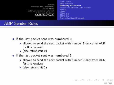
ABP Sender Rules
If the last packet sent was numbered 0,
allowed to send the next packet with number 1 only after ACKfor 0 is received(else retransmit 0)
If the last packet sent was numbered 1,
allowed to send the next packet with number 0 only after ACKfor 1 is received(else retransmit 1)
129 / 179

OutlineNetworks and Components
Layered ModelData Communication Channels
Delays and SwitchingReliable Data Transfer
Error ControlARQ ProtocolsAlternating Bit ProtocolReliable and Efficient Data TransferALOHACSMACSMA-CDCSMA-CAReservation Based Protocols
ABP Receiver Rules
If last packet received was numbered 0
If 1 received ACK and keep (new packet)If 0 received ACK and drop (retransmission of previous packet)
If last packet received was numbered 1
If 0 received ACK and keep (new packet)If 1 received ACK and drop (retransmission of previous packet)
130 / 179
OutlineNetworks and Components
Layered ModelData Communication Channels
Delays and SwitchingReliable Data Transfer
Error ControlARQ ProtocolsAlternating Bit ProtocolReliable and Efficient Data TransferALOHACSMACSMA-CDCSMA-CAReservation Based Protocols
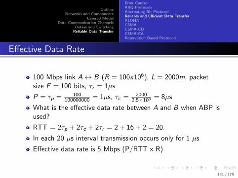
Effective Data Rate
100 Mbps link A↔ B (R = 100x106), L = 2000m, packetsize F = 100 bits, τr = 1µs
P = τp = 100100000000 = 1µs, τc = 2000
2.5×108 = 8µs
What is the effective data rate between A and B when ABP isused?
RTT = 2τp + 2τc + 2τr = 2 + 16 + 2 = 20.
In each 20 µs interval transmission occurs only for 1 µs
Effective data rate is 5 Mbps (P/RTT x R)
131 / 179

OutlineNetworks and Components
Layered ModelData Communication Channels
Delays and SwitchingReliable Data Transfer
Error ControlARQ ProtocolsAlternating Bit ProtocolReliable and Efficient Data TransferALOHACSMACSMA-CDCSMA-CAReservation Based Protocols
Improving Throughput
During the first micro second sender sends the first packet
Sender does nothing for 19 µs. ACK for first packet receivedafter 20µs
What if sender is allowed to send 20 packets before receivingthe ACK for the first packet?
Only after the ACK for the first packet is received the sendercan send packet 21
Only after the ACK for the second packet is received can thesender send packet 22, and so on
Window size of 20 packets
More generally, Window size ≥ RTT/packet duration
132 / 179

OutlineNetworks and Components
Layered ModelData Communication Channels
Delays and SwitchingReliable Data Transfer
Error ControlARQ ProtocolsAlternating Bit ProtocolReliable and Efficient Data TransferALOHACSMACSMA-CDCSMA-CAReservation Based Protocols
Pipelining Example, W ≥ RTT/τp = 13
0
0
RTT
1 2 3 4 5 6 7 8 9 10 11 12
13 packets (0 to 12) sent in one RTT
ACK for 0 processed; ready to send 13
13
1
ACK for 1 rcd; ready to send 14
14
2
133 / 179

OutlineNetworks and Components
Layered ModelData Communication Channels
Delays and SwitchingReliable Data Transfer
Error ControlARQ ProtocolsAlternating Bit ProtocolReliable and Efficient Data TransferALOHACSMACSMA-CDCSMA-CAReservation Based Protocols
Pipelining Example, W ≥ RTT/τp = 13
0
0
RTT
1
2 3 4 5 6 7 8 9 10 11 12
13 packets (0 to 12) sent in one RTT
ACK for 0 processed; ready to send 13
13
1
ACK for 1 rcd; ready to send 14
14
2
133 / 179

OutlineNetworks and Components
Layered ModelData Communication Channels
Delays and SwitchingReliable Data Transfer
Error ControlARQ ProtocolsAlternating Bit ProtocolReliable and Efficient Data TransferALOHACSMACSMA-CDCSMA-CAReservation Based Protocols
Pipelining Example, W ≥ RTT/τp = 13
0
0
RTT
1 2
3 4 5 6 7 8 9 10 11 12
13 packets (0 to 12) sent in one RTT
ACK for 0 processed; ready to send 13
13
1
ACK for 1 rcd; ready to send 14
14
2
133 / 179
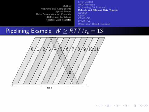
OutlineNetworks and Components
Layered ModelData Communication Channels
Delays and SwitchingReliable Data Transfer
Error ControlARQ ProtocolsAlternating Bit ProtocolReliable and Efficient Data TransferALOHACSMACSMA-CDCSMA-CAReservation Based Protocols
Pipelining Example, W ≥ RTT/τp = 13
0
0
RTT
1 2 3 4 5 6 7 8 9 10 11
12
13 packets (0 to 12) sent in one RTT
ACK for 0 processed; ready to send 13
13
1
ACK for 1 rcd; ready to send 14
14
2
133 / 179

OutlineNetworks and Components
Layered ModelData Communication Channels
Delays and SwitchingReliable Data Transfer
Error ControlARQ ProtocolsAlternating Bit ProtocolReliable and Efficient Data TransferALOHACSMACSMA-CDCSMA-CAReservation Based Protocols
Pipelining Example, W ≥ RTT/τp = 13
0
0
RTT
1 2 3 4 5 6 7 8 9 10 11 12
13 packets (0 to 12) sent in one RTT
ACK for 0 processed; ready to send 13
13
1
ACK for 1 rcd; ready to send 14
14
2
133 / 179

OutlineNetworks and Components
Layered ModelData Communication Channels
Delays and SwitchingReliable Data Transfer
Error ControlARQ ProtocolsAlternating Bit ProtocolReliable and Efficient Data TransferALOHACSMACSMA-CDCSMA-CAReservation Based Protocols
Pipelining Example, W ≥ RTT/τp = 13
0
0
RTT
1 2 3 4 5 6 7 8 9 10 11 12
13 packets (0 to 12) sent in one RTT
ACK for 0 processed; ready to send 13
13
1
ACK for 1 rcd; ready to send 14
14
2
133 / 179

OutlineNetworks and Components
Layered ModelData Communication Channels
Delays and SwitchingReliable Data Transfer
Error ControlARQ ProtocolsAlternating Bit ProtocolReliable and Efficient Data TransferALOHACSMACSMA-CDCSMA-CAReservation Based Protocols
Pipelining
The secret to higher throughput
ABP needs only half-duplex channels, for pipelining weimplicitly assume full duplex channels
ACKs and packets cross each other
Nodes may need to buffer packets when things do not go well
What is the buffer size needed?
How do we number packets and acknowledgements ?
134 / 179

OutlineNetworks and Components
Layered ModelData Communication Channels
Delays and SwitchingReliable Data Transfer
Error ControlARQ ProtocolsAlternating Bit ProtocolReliable and Efficient Data TransferALOHACSMACSMA-CDCSMA-CAReservation Based Protocols
Selective Repeat Protocol
Similar to ABP, with window size W packets
Or ABP is SRP with window size 1 packet
Buffer size (W . Why?)
Numbering packets? (2W unique numbers. Why?)
135 / 179

OutlineNetworks and Components
Layered ModelData Communication Channels
Delays and SwitchingReliable Data Transfer
Error ControlARQ ProtocolsAlternating Bit ProtocolReliable and Efficient Data TransferALOHACSMACSMA-CDCSMA-CAReservation Based Protocols
SRP Protocol
Sender Window (size 5)
Sent and ACKed
ACK pending
Not yet sent
3 4 5 6 7 8 9 0 1 2 3 4
SRP Sender Rules
Legal to send any packet within the window
Head of the queue blocked by an outstandingACK.
Sender window can not advance until ACK isreceived for the blocking packet.
Normally next unsent packet (blue) is sent.
On time-out for the blocking red packetresend the packet.
Sender may have to buffer up to W packets.
2W unique packet numbers — 0 to 2W − 1.
136 / 179

OutlineNetworks and Components
Layered ModelData Communication Channels
Delays and SwitchingReliable Data Transfer
Error ControlARQ ProtocolsAlternating Bit ProtocolReliable and Efficient Data TransferALOHACSMACSMA-CDCSMA-CAReservation Based Protocols
SRP Window
Rx. Window
received
pending
p.w f.w
3 4 5 6 7 8 9 0 1 2 3 4
Receiver Rules
Past Window and Future Window; each of size W .
Packets left of the Past Window: Receipt of ACKconfirmed by sender
Packets in the Past Window: ACKs not confirmed bysender
Future Window blocked by earliest pending packet.
Next packet received can be from either window
If packet from past window ACK and drop packet
If packet from future window ACK and store packet
Past Window is the lower bound on sender windowposition. Reception of 8 → ACK for 3 confirmed.
Future window is the upper bound on sender windowposition
137 / 179
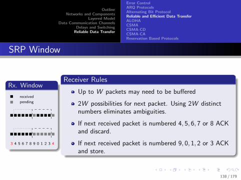
OutlineNetworks and Components
Layered ModelData Communication Channels
Delays and SwitchingReliable Data Transfer
Error ControlARQ ProtocolsAlternating Bit ProtocolReliable and Efficient Data TransferALOHACSMACSMA-CDCSMA-CAReservation Based Protocols
SRP Window
Rx. Window
received
pending
3 4 5 6 7 8 9 0 1 2 3 4
Receiver Rules
Up to W packets may need to be buffered
2W possibilities for next packet. Using 2W distinctnumbers eliminates ambiguities.
If next received packet is numbered 4, 5, 6, 7 or 8 ACKand discard.
If next received packet is numbered 9, 0, 1, 2 or 3 ACKand store.
138 / 179

OutlineNetworks and Components
Layered ModelData Communication Channels
Delays and SwitchingReliable Data Transfer
Error ControlARQ ProtocolsAlternating Bit ProtocolReliable and Efficient Data TransferALOHACSMACSMA-CDCSMA-CAReservation Based Protocols
Go Back N - GBN Protocol
Window size W
Sender logic is the same
Receiver does not buffer packets (no window)
Out of sequence packets are simply discarded
Periodically sends acknowledgement for the last receivedpacket number
Example, if Rx gets packets 1,2,3,4,5,7,8,9 the ACK for 5 issent. 7,8,9 not ACKed.
Sender retransmits 6,7,8,9...
139 / 179

OutlineNetworks and Components
Layered ModelData Communication Channels
Delays and SwitchingReliable Data Transfer
Error ControlARQ ProtocolsAlternating Bit ProtocolReliable and Efficient Data TransferALOHACSMACSMA-CDCSMA-CAReservation Based Protocols
Windowing Protocols in DL vs TL
Window size need not always be expressed in packets
If expressed in packets we assume equal duration packets(window size is “number of packet durations in one RTT”)
It can be in bits too (“number of bits that can be sent in oneRTT”)
Or bytes (“number of bytes that can be sent in one RTT”)
In transport layer window size is expressed in bytes
In data link layer, the link parameters like τp, τc , τr , RTT etc.,are known at design time. (Easy to compute W ≥ RTT/τp).
In TL how well do we know the “virtual link” parameters?How do we choose window size?
140 / 179

OutlineNetworks and Components
Layered ModelData Communication Channels
Delays and SwitchingReliable Data Transfer
Error ControlARQ ProtocolsAlternating Bit ProtocolReliable and Efficient Data TransferALOHACSMACSMA-CDCSMA-CAReservation Based Protocols
TDM in Autonomously Shared Channels
Multiple autonomous senders (stations) using the samemedium
Contention for medium access
Collision occurs when packets from any two stations overlap
Strategies for medium access control (MAC) used by the datalink layer
141 / 179

OutlineNetworks and Components
Layered ModelData Communication Channels
Delays and SwitchingReliable Data Transfer
Error ControlARQ ProtocolsAlternating Bit ProtocolReliable and Efficient Data TransferALOHACSMACSMA-CDCSMA-CAReservation Based Protocols
To Reserve Or Not?
Scheduling can be done with/without making reservations
No reservation
Stations themselves decide when to sendCollisions can occur
Reservation based
Reservation slotsCollision-free
142 / 179

OutlineNetworks and Components
Layered ModelData Communication Channels
Delays and SwitchingReliable Data Transfer
Error ControlARQ ProtocolsAlternating Bit ProtocolReliable and Efficient Data TransferALOHACSMACSMA-CDCSMA-CAReservation Based Protocols
Three Scenarios in No-Reservation MAC
Classification based on the nature of the medium.Can a station sense on-going transmissions from otherstations?Can occurrence of collisions be detected? (as soon as collisionoccurs)
Scenario 1: Stations contending for the medium can not sensetransmissions from other stations (eg., Satellitecommunication)Scenario 2: Stations can sense transmissions by otherstations, but can not detect collisions (can not listen andtransmit at the same time.Scenario 3: Stations can sense the medium, and can detectcollisions (eg. Ethernet).
143 / 179

OutlineNetworks and Components
Layered ModelData Communication Channels
Delays and SwitchingReliable Data Transfer
Error ControlARQ ProtocolsAlternating Bit ProtocolReliable and Efficient Data TransferALOHACSMACSMA-CDCSMA-CAReservation Based Protocols
ALOHA
n stations share a medium
Stations transmit whenever a packet arrives (from the higherlayer)
ACK sent by the receiver (satellite).
(No issues in transmissions from satellite to stations. Why?)
If no ACK received, stations wait for a random amount oftime and retransmit.
Assume all packets are of the same duration (we will use thatas the unit of time)
144 / 179

OutlineNetworks and Components
Layered ModelData Communication Channels
Delays and SwitchingReliable Data Transfer
Error ControlARQ ProtocolsAlternating Bit ProtocolReliable and Efficient Data TransferALOHACSMACSMA-CDCSMA-CAReservation Based Protocols
ALOHA
User
Time
A
B
C
D
E
145 / 179

OutlineNetworks and Components
Layered ModelData Communication Channels
Delays and SwitchingReliable Data Transfer
Error ControlARQ ProtocolsAlternating Bit ProtocolReliable and Efficient Data TransferALOHACSMACSMA-CDCSMA-CAReservation Based Protocols
ALOHA - Vulnerable Period
If a station is transmitting, what is the duration for which noother station should transmit?
Vulnerable duration is twice the packet duration
146 / 179

OutlineNetworks and Components
Layered ModelData Communication Channels
Delays and SwitchingReliable Data Transfer
Error ControlARQ ProtocolsAlternating Bit ProtocolReliable and Efficient Data TransferALOHACSMACSMA-CDCSMA-CAReservation Based Protocols
ALOHA - Vulnerable Period
Collides with the start of the shaded
frame
Collides with the end of the shaded
framet
to to+ t to+ 2t to+ 3t Time
Vulnerable
147 / 179

OutlineNetworks and Components
Layered ModelData Communication Channels
Delays and SwitchingReliable Data Transfer
Error ControlARQ ProtocolsAlternating Bit ProtocolReliable and Efficient Data TransferALOHACSMACSMA-CDCSMA-CAReservation Based Protocols
Slotted ALOHA
n stations have synchronized clocks
All stations agree on beginning of each time slot
Each slot the same as packet duration.
Stations transmit in the next time-slot (after arrival of thepacket)
If two or more stations receive a packet during a specific timeslot they all transmit at the next slot
Vulnerable period is one time slot.
148 / 179

OutlineNetworks and Components
Layered ModelData Communication Channels
Delays and SwitchingReliable Data Transfer
Error ControlARQ ProtocolsAlternating Bit ProtocolReliable and Efficient Data TransferALOHACSMACSMA-CDCSMA-CAReservation Based Protocols
Maximizing Throughput
Assume each station transmits with probability p in any slot
A packet is successful if no other station transmits during thesame slot
What is the probability that a packet transmitted during aspecific time-slot reaches the satellite?
S = Np(1− p)N−1
How do we maximize S?
Only thing the stations can do is control p
149 / 179

OutlineNetworks and Components
Layered ModelData Communication Channels
Delays and SwitchingReliable Data Transfer
Error ControlARQ ProtocolsAlternating Bit ProtocolReliable and Efficient Data TransferALOHACSMACSMA-CDCSMA-CAReservation Based Protocols
Maximizing Throughput S
Let p = x/N. Then S = x(1− x/N)N−1.
What value of x maximizes S? (Compute dSdx and set it to 0)
x = 1 maximizes S : or best choice of p is p = 1/N.
Best throughput S∗ = N(1/N)(1− 1/N)N−1 ≈ 1/e ≈ 0.368(for N →∞)
For “plain” (not slotted) ALOHA, p is the probability ofsending a packet in two time slots
Throughput ≈ 1/e in two packet durations
Or S∗P ≈ 1/2e ≈ 0.184 in each packet duration
Slotted ALOHA twice as efficient as plain ALOHA
150 / 179

OutlineNetworks and Components
Layered ModelData Communication Channels
Delays and SwitchingReliable Data Transfer
Error ControlARQ ProtocolsAlternating Bit ProtocolReliable and Efficient Data TransferALOHACSMACSMA-CDCSMA-CAReservation Based Protocols
Slotted ALOHA Example
1 Mbps link to satellite.
Packet size 1000 bits.
Satellite can receive 1,000 packets per sec.Packet-interval/slot-size 1 ms.
Best case scenario for slotted ALOHA
Occurs when all stations together send one packet per slotinterval (on an average)In each second 1000 packets transmitted (on an average)only 368 of them successful632 packets suffer collision every second (and have to beretransmitted)
151 / 179

OutlineNetworks and Components
Layered ModelData Communication Channels
Delays and SwitchingReliable Data Transfer
Error ControlARQ ProtocolsAlternating Bit ProtocolReliable and Efficient Data TransferALOHACSMACSMA-CDCSMA-CAReservation Based Protocols
Plain ALOHA Example
1 Mbps link to satellite.
Packet size 1000 bits.
Satellite can receive 1,000 packets per sec.Packet-interval/slot-size 1 ms.
Best case scenario for plain ALOHA
Occurs when all stations together send one packet every twopacket durations (on an average)In each second 500 packets are transmitted (by all stationstogether).Only 184 reach the satellite316 suffer collision (and have to be retransmitted)
152 / 179

OutlineNetworks and Components
Layered ModelData Communication Channels
Delays and SwitchingReliable Data Transfer
Error ControlARQ ProtocolsAlternating Bit ProtocolReliable and Efficient Data TransferALOHACSMACSMA-CDCSMA-CAReservation Based Protocols
Stability of ALOHA
What happens when p increases?
Simulate (Project idea 1)
Through simulations study the characteristics of ALOHA andslotted ALOHA
153 / 179

OutlineNetworks and Components
Layered ModelData Communication Channels
Delays and SwitchingReliable Data Transfer
Error ControlARQ ProtocolsAlternating Bit ProtocolReliable and Efficient Data TransferALOHACSMACSMA-CDCSMA-CAReservation Based Protocols
Channel Utilization With ALOHA
0.40
0.30
0.20
0.10
0 0.5 1.0 1.5G (attempts per packet time)
2.0 3.0
S (t
hrou
ghpu
t per
fram
e tim
e)
Slotted ALOHA: S = Ge–G
Pure ALOHA: S = Ge–2G
154 / 179

OutlineNetworks and Components
Layered ModelData Communication Channels
Delays and SwitchingReliable Data Transfer
Error ControlARQ ProtocolsAlternating Bit ProtocolReliable and Efficient Data TransferALOHACSMACSMA-CDCSMA-CAReservation Based Protocols
Carrier Sense Multiple Access Protocols
Listen first. If no one is currently using the channel, thentransmit
Collisions can still occur
Propagation delay (B has started transmission, but A does notknow that yet)A and B wait for C (which is currently transmitting) to finish;A and B start at the same time.
Collisions inferred through the lack of ACKs
Persistent and non-persistent CSMA
155 / 179
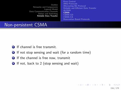
OutlineNetworks and Components
Layered ModelData Communication Channels
Delays and SwitchingReliable Data Transfer
Error ControlARQ ProtocolsAlternating Bit ProtocolReliable and Efficient Data TransferALOHACSMACSMA-CDCSMA-CAReservation Based Protocols
Non-persistent CSMA
1 If channel is free transmit.
2 If not stop sensing and wait (for a random time)
3 If the channel is free now, transmit
4 If not, back to 2 (stop sensing and wait)
156 / 179

OutlineNetworks and Components
Layered ModelData Communication Channels
Delays and SwitchingReliable Data Transfer
Error ControlARQ ProtocolsAlternating Bit ProtocolReliable and Efficient Data TransferALOHACSMACSMA-CDCSMA-CAReservation Based Protocols
Persistent CSMA
1-persistent - if busy keep sensing the line till it becomesavailable and start transmitting immediately
p-persistent (for slotted channels)
if busy keep sensing the channelIf free, transmit at the next slot - but with probability pProbability q = 1− p that a station will yield.Process continues till the packet has been transmitted oranother station takes over the channel.
157 / 179
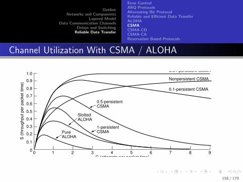
OutlineNetworks and Components
Layered ModelData Communication Channels
Delays and SwitchingReliable Data Transfer
Error ControlARQ ProtocolsAlternating Bit ProtocolReliable and Efficient Data TransferALOHACSMACSMA-CDCSMA-CAReservation Based Protocols
Channel Utilization With CSMA / ALOHA
1.0
0.9
0.8
0.5
0.4
0.3
0.2
0.1
0 1 2 3 4 5 6 7 8 90
0.6
0.7
S (t
hrou
ghpu
t per
pac
ket t
ime)
G (attempts per packet time)
Pure ALOHA
Slotted ALOHA
1-persistent CSMA
0.1-persistent CSMA
0.5-persistent CSMA
Nonpersistent CSMA
0.01-persistent CSMA
158 / 179

OutlineNetworks and Components
Layered ModelData Communication Channels
Delays and SwitchingReliable Data Transfer
Error ControlARQ ProtocolsAlternating Bit ProtocolReliable and Efficient Data TransferALOHACSMACSMA-CDCSMA-CAReservation Based Protocols
Project Idea 2
Analyze throughput vs traffic (total attempts per packetduration) for CSMA
obviously, will depend on the strategy (non-persistent,p-persistent)
159 / 179

OutlineNetworks and Components
Layered ModelData Communication Channels
Delays and SwitchingReliable Data Transfer
Error ControlARQ ProtocolsAlternating Bit ProtocolReliable and Efficient Data TransferALOHACSMACSMA-CDCSMA-CAReservation Based Protocols
CSMA With Collision Detection (CSMA-CD)
In CSMA (and ALOHA) collisions are inferred through thelack of ACKs
What if stations can send and listen at the same time?
Stations can stop transmitting as soon as a they detect another transmission.
Collision uses up a smaller fraction of the time.CSMA-Protocol
Stations sense channel, and transmit only if the channel is free.If collision is detected - stop sending the packet (only part of apacket may be sent).Retry (p-persistent? non-persistent?)Actually p-persistent with dynamic p (more on this later)
160 / 179

OutlineNetworks and Components
Layered ModelData Communication Channels
Delays and SwitchingReliable Data Transfer
Error ControlARQ ProtocolsAlternating Bit ProtocolReliable and Efficient Data TransferALOHACSMACSMA-CDCSMA-CAReservation Based Protocols
CSMA-CD States
Contention slots
Contention period
Transmission period
Idle period
to
Frame Frame Frame Frame
Time
161 / 179
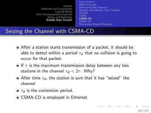
OutlineNetworks and Components
Layered ModelData Communication Channels
Delays and SwitchingReliable Data Transfer
Error ControlARQ ProtocolsAlternating Bit ProtocolReliable and Efficient Data TransferALOHACSMACSMA-CDCSMA-CAReservation Based Protocols
Seizing the Channel with CSMA-CD
After a station starts transmission of a packet, it should beable to detect within a period τd that no collision is going tooccur for that packet.
If τ is the maximum transmission delay between any twostations in the channel τd < 2τ . Why?
After time τd , the station is sure that it has “seized” thechannel
τd is the contention period.
CSMA-CD is employed in Ethernet
162 / 179

OutlineNetworks and Components
Layered ModelData Communication Channels
Delays and SwitchingReliable Data Transfer
Error ControlARQ ProtocolsAlternating Bit ProtocolReliable and Efficient Data TransferALOHACSMACSMA-CDCSMA-CAReservation Based Protocols
2τ for Collision Detection
Packet starts at time 0A B A B
Packet almost at B at τ - ∋
Collision at time τ
A B
Noise burst gets back to A at 2τ
A B
(a) (b)
(c) (d)
163 / 179

OutlineNetworks and Components
Layered ModelData Communication Channels
Delays and SwitchingReliable Data Transfer
Error ControlARQ ProtocolsAlternating Bit ProtocolReliable and Efficient Data TransferALOHACSMACSMA-CDCSMA-CAReservation Based Protocols
Restrictions On Packet Size
With CSMA-CD there is also a restriction on minimum packetduration!
What happens if packet duration is less than 2τ?
It is possible that A completes the entire packet before itsensed the collision.
So A does not even know that a collision occurred!
Packet sizes have to be chosen such that the packet durationis greater than 2τ
164 / 179

OutlineNetworks and Components
Layered ModelData Communication Channels
Delays and SwitchingReliable Data Transfer
Error ControlARQ ProtocolsAlternating Bit ProtocolReliable and Efficient Data TransferALOHACSMACSMA-CDCSMA-CAReservation Based Protocols
Minimum Packet Size
For 10 Mbps LAN, maximum distance of 2500 m between twostations
In practice, upto 4 repeaters may be used
Propagation delay 25µs — 10 + 15µs overall repeater delay.
τd = 50µs.
Smallest allowed packet size is 500 bits (Ethernet prescribes64 bytes (512 bits) as the minimum packet size).
For 100 Mbps LAN Ethernet standard recommends maxlength 250 m
1µs + 1.5µs repeater delay. τd = 5µs.
Minimum packet size is again 500 bits (64 bytes)
165 / 179

OutlineNetworks and Components
Layered ModelData Communication Channels
Delays and SwitchingReliable Data Transfer
Error ControlARQ ProtocolsAlternating Bit ProtocolReliable and Efficient Data TransferALOHACSMACSMA-CDCSMA-CAReservation Based Protocols
CSMA-CD Efficiency
Let average number of contention slots be x
The channel is occupied by
useful packets of duration P anduseless contentions (on an average x contentions of duration2τ each).
Efficiency
ν =P
P + 2τx
x ≈ e (the reason is a little complex for now. We will get tothis later)
166 / 179

OutlineNetworks and Components
Layered ModelData Communication Channels
Delays and SwitchingReliable Data Transfer
Error ControlARQ ProtocolsAlternating Bit ProtocolReliable and Efficient Data TransferALOHACSMACSMA-CDCSMA-CAReservation Based Protocols
CSMA-CD Efficiency
F - frame size (in bits)
R - data rate (bits per sec)
P = FR
c - velocity of propagation
L - maximum separation between two stations)
τ = Lc
ν =P
P + 2τe=
1
1 + 2RLe/cF
167 / 179
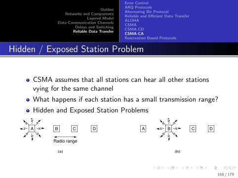
OutlineNetworks and Components
Layered ModelData Communication Channels
Delays and SwitchingReliable Data Transfer
Error ControlARQ ProtocolsAlternating Bit ProtocolReliable and Efficient Data TransferALOHACSMACSMA-CDCSMA-CAReservation Based Protocols
Hidden / Exposed Station Problem
CSMA assumes that all stations can hear all other stationsvying for the same channel
What happens if each station has a small transmission range?
Hidden and Exposed Station Problems
A
(a)
B DC
Radio range
A
(b)
B DC
168 / 179

OutlineNetworks and Components
Layered ModelData Communication Channels
Delays and SwitchingReliable Data Transfer
Error ControlARQ ProtocolsAlternating Bit ProtocolReliable and Efficient Data TransferALOHACSMACSMA-CDCSMA-CAReservation Based Protocols
Hidden Station Problem
A→ B.
C senses medium but does not hear A’s transmission as C isout of range.
If C transmits we have collision at B.
Hidden Station Problem. A is hidden from C
A
(a)
B DC
Radio range
A
(b)
B DC
169 / 179
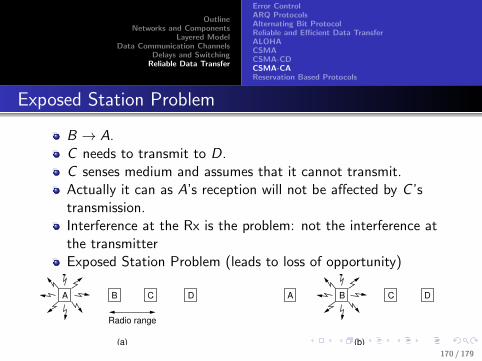
OutlineNetworks and Components
Layered ModelData Communication Channels
Delays and SwitchingReliable Data Transfer
Error ControlARQ ProtocolsAlternating Bit ProtocolReliable and Efficient Data TransferALOHACSMACSMA-CDCSMA-CAReservation Based Protocols
Exposed Station Problem
B → A.C needs to transmit to D.C senses medium and assumes that it cannot transmit.Actually it can as A’s reception will not be affected by C ’stransmission.Interference at the Rx is the problem: not the interference atthe transmitterExposed Station Problem (leads to loss of opportunity)
A
(a)
B DC
Radio range
A
(b)
B DC
170 / 179
OutlineNetworks and Components
Layered ModelData Communication Channels
Delays and SwitchingReliable Data Transfer
Error ControlARQ ProtocolsAlternating Bit ProtocolReliable and Efficient Data TransferALOHACSMACSMA-CDCSMA-CAReservation Based Protocols
MACA Protocol
Multiple Access with Collision Avoidance (MACA)
Rx should send a short frame to indicate that it is ready toreceive from a source.
Other stations hearing the Rx will yield.
RTS (Request to Send) and CTS (Clear to Send) packets.
171 / 179
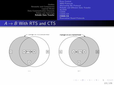
OutlineNetworks and Components
Layered ModelData Communication Channels
Delays and SwitchingReliable Data Transfer
Error ControlARQ ProtocolsAlternating Bit ProtocolReliable and Efficient Data TransferALOHACSMACSMA-CDCSMA-CAReservation Based Protocols
A→ B With RTS and CTS
(a) (b)
Range of A's transmitter
A RTS
E
B DC A CTS
E
B DC
Range of B's transmitter
172 / 179

OutlineNetworks and Components
Layered ModelData Communication Channels
Delays and SwitchingReliable Data Transfer
Error ControlARQ ProtocolsAlternating Bit ProtocolReliable and Efficient Data TransferALOHACSMACSMA-CDCSMA-CAReservation Based Protocols
A→ B RTS. C hears RTS.
B → A CTS response.
C waits a reasonable amount of time, but does not hear CTS
C can now initiate a transmission on it’s own (by sending anRTS)
D hears CTS but not RTS.
D should desist until the data packet following CTS isfinished.
(a) (b)
Range of A's transmitter
A RTS
E
B DC A CTS
E
B DC
Range of B's transmitter
173 / 179

OutlineNetworks and Components
Layered ModelData Communication Channels
Delays and SwitchingReliable Data Transfer
Error ControlARQ ProtocolsAlternating Bit ProtocolReliable and Efficient Data TransferALOHACSMACSMA-CDCSMA-CAReservation Based Protocols
MACA Rules
RTS and CTS packets indicate sender, intended receiver, andsize of data packet to be sent.
If you hear only RTS (A,B, n)wait for some time to make sure receiver B is out of range
before initiating an RTS (to some other station)
If you hear CTS (either CTS only or both RTS and CTS) thereceiver is within range.
do not transmit until the data transmission (n bytes fromA→ B) is completed.
174 / 179

OutlineNetworks and Components
Layered ModelData Communication Channels
Delays and SwitchingReliable Data Transfer
Error ControlARQ ProtocolsAlternating Bit ProtocolReliable and Efficient Data TransferALOHACSMACSMA-CDCSMA-CAReservation Based Protocols
MACAW - MACA for Wireless
Some enhancements to MACA
MAC layer acknowledgements. To receive ACK there shouldbe no collision at the transmitter of the original packet. Soexposed station problem is deliberately not addressed.
CSMA for transmitting RTS
Back-off algorithm for each source-destination pair instead offor each station.
Additional information exchange about congestion.
175 / 179

OutlineNetworks and Components
Layered ModelData Communication Channels
Delays and SwitchingReliable Data Transfer
Error ControlARQ ProtocolsAlternating Bit ProtocolReliable and Efficient Data TransferALOHACSMACSMA-CDCSMA-CAReservation Based Protocols
Collision-Free Protocols
Bit-map protocol
Binary Countdown
Especially suitable for small number of stations that are closeto each other (very little delay)
176 / 179

OutlineNetworks and Components
Layered ModelData Communication Channels
Delays and SwitchingReliable Data Transfer
Error ControlARQ ProtocolsAlternating Bit ProtocolReliable and Efficient Data TransferALOHACSMACSMA-CDCSMA-CAReservation Based Protocols
Bit Map Protocol
0 1
1 1 1 1 1 1 5 11 3 7
2 3 4 5 6 7 0 1 2 3 4 5 6 7 0 1 2 3 4 5 6 7
18 Contention slotsFrames
8 Contention slots
2
d
177 / 179

OutlineNetworks and Components
Layered ModelData Communication Channels
Delays and SwitchingReliable Data Transfer
Error ControlARQ ProtocolsAlternating Bit ProtocolReliable and Efficient Data TransferALOHACSMACSMA-CDCSMA-CAReservation Based Protocols
Binary Countdown
0 0 1 0 0 – – –
0 1 2 3Bit time
0 1 0 0 0 – – –
1 0 0 1 1 0 0 –
1 0 1 0 1 0 1 0
1 0 1 0Result
Stations 0010 and 0100 see this
1 and give up
Station 1001 sees this 1 and gives up
178 / 179

OutlineNetworks and Components
Layered ModelData Communication Channels
Delays and SwitchingReliable Data Transfer
Error ControlARQ ProtocolsAlternating Bit ProtocolReliable and Efficient Data TransferALOHACSMACSMA-CDCSMA-CAReservation Based Protocols
Efficiency of Collision-Free Protocols
Width of each reservation slot should be of the order of themaximum delay between stations (so there is no ambiguity asto which station(s) is making a reservation)
Number of reservation slots proportional to number ofstations (in bit-map protocol)
Number of reservation slots proportional to log2 of number ofstations for each packet (in binary countdown)
However, if number of packets is proportional to number ofstations, even for binary countdown the total overhead (forreservation slots) will depend on the number of stations!
179 / 179